EP4016781A1 - Chargeur et boitier de chargeur à zone de fixation - Google Patents
Chargeur et boitier de chargeur à zone de fixation Download PDFInfo
- Publication number
- EP4016781A1 EP4016781A1 EP20214320.2A EP20214320A EP4016781A1 EP 4016781 A1 EP4016781 A1 EP 4016781A1 EP 20214320 A EP20214320 A EP 20214320A EP 4016781 A1 EP4016781 A1 EP 4016781A1
- Authority
- EP
- European Patent Office
- Prior art keywords
- fastening
- charger
- housing
- attachment
- area
- Prior art date
- Legal status (The legal status is an assumption and is not a legal conclusion. Google has not performed a legal analysis and makes no representation as to the accuracy of the status listed.)
- Pending
Links
Images


Classifications
-
- H—ELECTRICITY
- H02—GENERATION; CONVERSION OR DISTRIBUTION OF ELECTRIC POWER
- H02J—CIRCUIT ARRANGEMENTS OR SYSTEMS FOR SUPPLYING OR DISTRIBUTING ELECTRIC POWER; SYSTEMS FOR STORING ELECTRIC ENERGY
- H02J7/00—Circuit arrangements for charging or depolarising batteries or for supplying loads from batteries
- H02J7/0042—Circuit arrangements for charging or depolarising batteries or for supplying loads from batteries characterised by the mechanical construction
-
- H—ELECTRICITY
- H02—GENERATION; CONVERSION OR DISTRIBUTION OF ELECTRIC POWER
- H02J—CIRCUIT ARRANGEMENTS OR SYSTEMS FOR SUPPLYING OR DISTRIBUTING ELECTRIC POWER; SYSTEMS FOR STORING ELECTRIC ENERGY
- H02J7/00—Circuit arrangements for charging or depolarising batteries or for supplying loads from batteries
- H02J7/0013—Circuit arrangements for charging or depolarising batteries or for supplying loads from batteries acting upon several batteries simultaneously or sequentially
-
- H—ELECTRICITY
- H02—GENERATION; CONVERSION OR DISTRIBUTION OF ELECTRIC POWER
- H02J—CIRCUIT ARRANGEMENTS OR SYSTEMS FOR SUPPLYING OR DISTRIBUTING ELECTRIC POWER; SYSTEMS FOR STORING ELECTRIC ENERGY
- H02J7/00—Circuit arrangements for charging or depolarising batteries or for supplying loads from batteries
- H02J7/0042—Circuit arrangements for charging or depolarising batteries or for supplying loads from batteries characterised by the mechanical construction
- H02J7/0045—Circuit arrangements for charging or depolarising batteries or for supplying loads from batteries characterised by the mechanical construction concerning the insertion or the connection of the batteries
Definitions
- the invention relates to a charger housing that includes an operating side with at least one battery charging location that is accessible from the operating side and a first fastening area on the outside of the housing on a first fastening side that differs from the operating side, the first fastening area being set up for detachably fastening the charger housing to a fastening base and has one or more first fastening elements, and a charger equipped with such a charger housing.
- Charger housings of this type are used for chargers, more precisely electrical chargers, which are used for electrical charging, i.e. electrical charging, serve a respective rechargeable electric battery unit.
- the relevant battery unit is introduced into the battery charging station from the operating side of the charger housing. It can then be removed from this again on the operating side of the charger housing, in particular after charging has taken place.
- the charger can be designed as a single-station charger, which has a single battery charging station, or as a multi-station charger, which has multiple battery charging stations.
- battery unit in the present case includes an electrical energy store of any conventional battery type, in particular of the type of so-called battery packs, such as are often used to supply electrical energy, for example, to electrically operated gardening and forestry equipment and electrically operated do-it-yourself devices.
- the charger housing Via its first attachment area, e.g. a rear attachment area or a rear attachment surface, the charger housing can be detachably attached to an e.g horizontally oriented floor or table surface or the like.
- the first fastening area can rest against a corresponding area of the fastening base, and the detachable fastening takes place by means of the associated fastening element or elements.
- these fastening elements can be, for example, screw fastening openings, Act Velcro elements, magnetic elements, detachable adhesive fasteners or other conventional detachable fasteners.
- the patent specification GB 2497372B discloses a modular charger with a chassis-like, cuboid or strip-shaped charger housing of the type mentioned at the outset, which has battery receptacle bodies that can be attached in a modular manner on a front side that acts as an operating side, each containing a battery charging station for receiving and charging a suitable battery unit.
- this charger housing is provided with a screw opening in each of its four corners or side areas as rear fastening elements, which means that it can be attached to a vertically oriented wall, e.g.
- pedestal elements can be mounted on the opposite narrow sides of this strip-shaped charger housing, with which the housing can be set up on a horizontal table top or the like.
- the invention is based on the technical problem of providing a charger housing of the type mentioned at the outset, which can be implemented with comparatively little effort and is improved compared to the above-mentioned prior art, in particular with regard to its fastening options and the resulting versatility in use, and a charger equipped with it .
- the invention solves this problem by providing a charger housing with the features of claim 1 and a charger with the features of claim 11.
- Advantageous developments of the invention that contribute to solving this and other problems are specified in the dependent claims, their content including all Combinations of features resulting from the back-references to the claims are hereby made fully part of the content of the description by reference.
- the charger housing in addition to its first attachment area on the outside of the housing, includes a second attachment area on the outside of the housing on one of the operating side and the first attachment side Different second attachment side, wherein the second attachment area is set up for releasably attaching the charger housing to an attachment base and has one or more side attachment elements.
- the charger housing according to the invention can be attached via the first attachment area or attachment via the second attachment area to a respective, e.g. flat attachment base, such as a vertically oriented wall surface or a horizontally oriented table surface or another type, vertical or horizontal or anywhere else in space oriented base, which can be flat, curved and/or profiled, i.e. provided with fastening projections or fastening recesses, for example.
- the respective first or second fastening area can be a single area, i.e. an area in the mathematical sense, with a more punctiform or more extensive extent, or a multi-part area consisting of the totality of several such sub-areas separated from one another. This includes the possibility that the respective fastening area is formed by one or more punctiform or flat fastening projections which protrude in relation to a remaining part of the relevant fastening side.
- the charger housing according to the invention offers variable, detachable fastening options with relatively little effort, which increases its versatility in use and especially its flexible positioning for the charging operation of the associated charger.
- the second fastening elements as for the first fastening elements, screw fastening openings, hook and loop fastener elements, magnetic elements, detachable adhesive connection elements or adhesive connection surfaces or other conventional detachable fastening elements can be used, for example.
- the associated fastening base has corresponding fastening elements which interact with those of the charger housing in a detachably connecting manner, such as corresponding screw bolts, Velcro fastener elements, magnetic elements or detachable adhesive connection elements or surfaces.
- the charging device according to the invention has such a charging device housing according to the invention.
- the first fastening area comprises a plurality of separate, e.g. more planar or alternatively more punctiform, first fastening zones which lie in a common first fastening plane.
- first fastening zones which lie in a common first fastening plane.
- the charger housing can rest against such a fastening base at correspondingly several zones spaced apart from one another, so that the charger housing can be held with good support on the respective fastening base.
- the first fastening area can be formed by a single flat surface area, e.g. a rear surface, or by several separate, e.g. flat or punctiform, first fastening zones which lie in two or more different planes.
- the first fastening area comprises several separate, e.g. flat or punctiform, fastening zones, each of which has at least one first screw fastening opening as the first fastening element.
- first fastening side can provide a single flat surface as the first fastening area, and/or other first fastening elements can be used, e.g. Velcro strips or magnetic elements.
- the first attachment side has a polygonal shape and the first attachment zones are located at corner or side areas of the first attachment side.
- the first fastening zones of the charging device housing, at which associated first fastening points are located, are therefore relatively far apart, which benefits the stability of the fastening of the charging device housing to the fastening base.
- the first fastening side can be, for example, circular or oval in shape, and in the case of several separate first Fastening zones, these are preferably arranged with relatively large mutual distances.
- the second fastening area comprises a plurality of separate, e.g. two-dimensional or punctiform, second fastening zones which lie in a common second fastening plane.
- the charger housing can again rest against an associated mounting base via the second mounting zones located in a common plane at a corresponding number of zones spaced apart from one another, so that the charger housing can be held on this mounting base with good support.
- the second attachment area can be formed by a single flat surface, e.g. a flat side surface, or by several separate, e.g. flat or punctiform, second attachment zones that lie in two or more different planes.
- the second fastening area comprises several separate, e.g. flat or punctiform fastening zones, each of which has at least one second screw fastening opening as the second fastening element.
- This in turn represents a structurally simple realization that is favorable in terms of fastening stability.
- the housing side in question can, for example, provide a single flat surface as fastening surface, and/or other second fastening elements can be used, e.g. Velcro strips or magnetic elements.
- the second attachment side has a polygonal shape, and the second attachment zones, which are, for example, two-dimensional or punctiform, are located in corner or side areas of the second attachment side.
- the areas of the charger housing where the associated second attachment points are located are relatively far apart, which benefits the stability of this attachment of the charger housing to the attachment base in question.
- the housing side concerned can be of circular or oval shape, for example, and in the case of several separate second attachment zones, these are preferably arranged at relatively large mutual distances.
- the charging device housing has fastening supports on the outside, each of which has the first fastening element or elements on a first support side and the second fastening element or elements on a second support side.
- the fastening supports act as fastening components of the housing and can also contribute to the stability of the housing. They can be formed in one piece with the rest of the housing or can be prefabricated separately and mounted on this. Alternatively, the charger housing can, for example, be fastened directly to a respective fastening base via unsupported areas of the outer wall of the housing.
- the respective outside fastening support has a support foot area forming the first support side and a support side area forming the second support side.
- the charging device housing can optionally be fixed to a mounting base with its first mounting side via the base area of the respective mounting bracket and to a mounting base via the longitudinal side area of the respective mounting bracket with its second mounting side.
- the two support sides of the respective fastening support, which have the first or second fastening element or elements can be formed, for example, by two adjacent support longitudinal side areas.
- the respective external fastening support has at least two spaced apart first fastening elements on the first side of the support and/or at least two spaced apart second fastening elements on the second side of the support. This enables a stable multi-point attachment of the charger housing to the attachment base via the attachment supports.
- the respective mounting bracket has, for example, only a single first or second fastener on its respective bracket side.
- the second fastening zone of the respective fastening support has at least two second fastening elements which are arranged at a distance from one another. This contributes to good stability and strength this attachment of the charger housing to a relevant mounting pad.
- the charger housing forms a cuboid housing, and the operating side is formed by a cuboid main side, i.e. a cuboid side with the greatest surface area, or a cuboid long side, i.e. a cuboid side between the two cuboid main sides, of the housing cuboid.
- a cuboid main side i.e. a cuboid side with the greatest surface area
- a cuboid long side i.e. a cuboid side between the two cuboid main sides
- the charger housing has a different geometric outer contour, e.g. a triangular cross-section or a pyramid shape.
- the outside fastening supports are arranged on the cuboid side edges of the housing cuboid. This contributes to an optimization of the optional fixing of the cuboid charger housing to the respective base on the first or the second attachment side if these two attachment sides adjoin one another at the relevant cuboid side edges.
- the outside mounting brackets may be located, for example, at central areas of corresponding cuboid sides of the charger housing.
- the charger according to the invention is used in a manner known per se for electrically charging a rechargeable battery unit, the battery unit being in particular a battery pack for supplying electrical energy to an electrically operated gardening and forestry equipment or an electrically operated one DIY device can act.
- the charger includes a charger housing with an operating side 1 and at least one battery charging station 2 that is accessible from the operating side 1.
- the charger housing has four battery charging stations 2, in each of which a rechargeable battery pack 16 can be accommodated for electrical charging by the charger.
- the charger can be connected to an electrical power supply via a mains cable 18 .
- the charger housing has only a single battery charging slot 2 in which a single rechargeable battery pack 16 can be accommodated for electrical charging by the charger.
- the operating side 1 is also referred to as the front side or top of the charger housing and the opposite side of the charger housing is referred to as the back or bottom.
- the charger housing has a first fastening area 3 on the outside of the housing on a first fastening side 4 different from the operating side 1, the first fastening area 3 being set up for detachably fastening the charger housing to a fastening base and having one or more first fastening elements 5.
- the charger housing also includes a second fastening area 6 on the outside of the housing on a second fastening side 7 that is different from the operating side 1 and the first fastening side 4, with the second fastening region 6 also being set up for the detachable fastening of the charger housing to a fastening base and having one or more second fastening elements 8 .
- the first fastening side 4 is a housing side opposite to the operating side 1
- the second fastening side 7 is a housing side running between the operating side 1 and the first fastening side 4 .
- it can be the other way around, or both fastening sides 4, 7 are housing sides running between the operating side 1 and the side opposite this.
- the charging device housing can be fastened in a very variable manner either on its first fastening side 4 or on its second fastening side 7 on any spatially oriented base.
- the embodiment of FIG Figures 4 to 7 the optional attachment of the charger with its charger housing on the back, ie with its rear on a vertical 20v base, see 4 , or on the back of a horizontal support 20 H , see figure 5 , or laterally, ie with one of the front side or operating side 1 adjacent Housing side, on the horizontal support 20 H , see 6 , or on the side of the vertical support 20v, with the front operating side 1 in the fastening positions of the housing according to FIGS Figures 4 and 6 forward and in the mounting positions of the housing according to the Figures 5 and 7 pointing up.
- the operating side 1 is easily accessible for the user to insert a battery pack 16 to be charged into the battery charging station 2 and to remove the battery pack 16 from the same after the charging process has taken place.
- FIG. 9 illustrates the attachment of this charging device with its charging device housing via its underside or rear side as the first attachment side 4 to the base 20v, which is again vertically oriented here.
- 10 illustrates the rear attachment of the charger housing to the base 20 H , which is again horizontal here.
- 11 12 illustrates a side attachment of the charger housing to the horizontal base 20H , and 12 Illustrates the side attachment of the charger housing to the vertical pad 20v.
- the charger housing points forward with its operating side 1, in the fastening positions of the 10 and 12 it has its attachment side 1 facing upwards.
- the operating side 1 for inserting and removing the battery packs 16 into or out of the battery charging stations 2 is easily accessible to the user.
- the charger housing Since the charger housing is fastened in a detachable manner both on its first fastening side 4 and on its second fastening side 7, the charger housing can be removed from a fastening base and in a different orientation on the same base or in the same or different orientation on a different base be attached again, whereby the charger can be positioned very flexibly and securely on a respective surface for operation.
- the first fastening area 3 contains a plurality of separate first fastening zones which lie in a common first fastening plane, four separate first fastening zones in each case in the examples shown 3 1 , 3 2 , 3 3 , 3 4 , in alternative realizations only two or three or more than four attachment zones.
- the attachment zones 3 1 to 3 4 can be more of a punctiform or more extensive type, depending on requirements. Because they lie in a common plane, they are particularly well-adapted to attaching the charger case to a suitably flat surface.
- the first fastening area 3 comprises several separate first fastening zones, each of which has at least one first screw fastening opening 9 as the first fastening element 5, as is the case in the examples shown for the first fastening zones 3 1 to 3 4 .
- a respective screw bolt 13 can interact with the first screw fastening opening 9, for example in FIGS Figures 4, 5 and 13 to recognize to fix the charger housing in the relevant first attachment zone 3 1 to 3 4 on the associated base by means of a corresponding screw detachable.
- a magnetic element or a Velcro element for example, can be provided as the first fastening element 5 in the respective first fastening zone 3 1 to 3 4 .
- the first attachment side 4 has a polygonal shape, and the first attachment zones are located at corner or side areas of the first attachment side 4.
- the first attachment side 4 has a square, specifically rectangular, shape, and the first attachment zones 3 1 to 3 4 are located in corner or side areas 4 1 , 4 2 , 4 3 , 4 4 of this rectangular first fastening side 4.
- the first fastening zones 3 1 to 3 4 are at relatively large distances from one another across the first fastening side 4 distributed, which promotes the stability of the attachment of the charger housing to the base.
- the second fastening area 6 comprises a plurality of separate second fastening zones which lie in a common second fastening plane.
- the second fastening area 6 comprises four separate second fastening zones 6 1 , 6 2 , 6 3 , 6 4 in each case. By these lying in the common second attachment plane, this in turn enables problem-free attachment of the charging device housing via its second attachment side 7 to a plan base.
- the second attachment area 6 includes two, three or more than four second attachment zones.
- the attachment zones 6 1 to 6 4 can in turn each have a more punctiform or more flat shape, depending on requirements.
- the second fastening area 6 comprises a plurality of separate second fastening zones, each of which has at least one second screw fastening opening 12 as the second fastening element 8, as is the case in the examples shown for the four second fastening zones 6 1 to 6 4 in each case.
- a respective screw bolt 13 can in turn interact with the screw fastening opening 12, for example in FIGS Figures 6 and 7 to recognize to attach the charger housing in the relevant second attachment zone 6 1 to 6 4 with its second attachment side 7 by a detachable screw connection to a base.
- a magnetic element or a Velcro element is provided as the second fastening element 8, for example.
- the second fastening side 7 has a polygonal shape, in the examples shown specifically a square or rectangular shape, and the second fastening zones 6 1 to 6 4 are located in corner or side areas of the second fastening side 7, in the example the Figures 1 to 7 at four corner areas 7 1 , 7 2 , 7 3 , 7 4 and in the example Figures 8 to 13 on two side areas 7 5 , 7 6 .
- a stable attachment of the charger housing with its second attachment side 7 to a base can thus be achieved as a corresponding multi-point attachment at attachment points that are relatively far apart from one another.
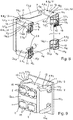
- the charger housing includes, as in the embodiment of Figures 8 to 13 , External attachment supports 19 1 , 19 2 , 19 3 , 19 4 , each having the first attachment element(s) 5 on a first support side 10 and the second attachment element(s) 8 on a second support side 11 .
- the fastening supports 19 1 to 19 4 assume the fastening function for the charger housing and can be specially designed for this purpose, so that the rest of the charger housing can be designed independently of this fastening function.
- the mounting brackets 19 1 , 19 2 , 19 3 , 19 4 can be in one piece, or as in the example shown, prefabricated separately from the rest of the housing and connected to it detachably or permanently, ie not detachably detachable.
- the respective outside mounting bracket 19 1 to 19 4 as in the example shown Figures 8 to 13 , a support foot area 19 F forming the first support side 10 and a support longitudinal side area 19 S forming the second support side 11 .
- the charger housing can thus optionally be attached via the four base areas 19 F of the mounting brackets 19 1 to 19 4 with its first attachment side 4 or via the longitudinal side areas 19s of two of the mounting brackets 19 1 to 19 4 with its second fastening side 7 can be releasably fixed to a respective base, in which case the two fastening sides 4, 7 are two adjoining or adjacent housing sides, since the support base area 19 F and the support longitudinal side area 19s of the attachment supports 19 1 to 19 4 are correspondingly adjacent or adjoining surface areas of the fastening supports 19 1 to 19 4 .
- the fastening supports 19 1 to 19 4 each have two of the fastening zones 6 1 to 6 4 on their longitudinal side area 19s.
- the charging device housing can also be attached to a base with these attachment supports 19 1 to 19 4 on one of its other longitudinal sides as a third attachment side between its operating side 1 and its first attachment side 3 .
- each mounting bracket 19 1 to 19 4 includes a plurality of, for example two, first mounting elements 5 1 , 5 2 and second mounting elements 8 1 , 8 2 on its first support side 10 and on its second support side 11 .
- first mounting elements 5 1 , 5 2 and second mounting elements 8 1 , 8 2 on its first support side 10 and on its second support side 11 .
- the charger housing forms a cuboid housing
- the operating side 1 is of a cuboid main side Q H1 , as in the example Figures 8 to 13 , or from a cuboid long side Q L1 of the housing cuboid, as in the example Figures 1 to 7 , educated.
- This cuboid shape of the charger housing is ideal for many charger applications, both in terms of the placement of the battery units to be charged and in terms of the variable, detachable attachment of the charger housing to any documents with any spatial orientation of the respective attachment document and thus the charger housing detachably fixed thereto.
- the outside mounting brackets 19 1 to 19 4 are arranged on cuboid side edges Q K1 , Q K2 , Q K3 , Q k4 and/or on cuboid corner areas Q E1 , Q E2 , Q E3 , Q E4 of the housing cuboid.
- the fastening supports 19 1 to 19 4 each along a cuboid side edge Q K1 to Q K4 and in an adjoining cuboid corner area Q E1 to Q E4 .
- the charging device housing can be attached either with its rear or underside as the first attachment side 4 via the support base areas 19 F of the attachment supports 19 1 to 19 4 or with a cuboid longitudinal side Q L2 as its second attachment side 7 via the support longitudinal side areas 19s, as required of the mounting brackets 19 1 to 19 4 can be detachably fixed to any horizontally, vertically or otherwise spatially oriented base.
- the charging device housing is not cuboid, but rather pyramid-shaped or some other polyhedron shape, or a housing shape in which one or more housing sides are arched or curved, e.g. in the shape of a spherical shell.
- the outside mounting brackets project rearwardly beyond the remaining intermediate housing wall area of the rear of the charger housing outside of the mounting brackets and/or laterally outwards over the remaining intermediate housing wall area of the relevant ones side of the housing.
- the outside attachment supports 19 1 , 19 2 , 19 3 , 19 4 protrude both to the rear and to the outside.
- the fact that the mounting brackets protrude to the rear means that when the charger housing is mounted on a base from the rear, its rear wall does not come into full contact with the base, but rather a gap remains between them.
- the lateral overhang of the mounting brackets has the analogous result that the charger housing does not come into full contact with the surface with its relevant housing side when installed on the side, but a gap remains between them.
- the attachment supports can act as spacers for mounting the respective charging device housing on a base and/or as spacers for placing several charging device housings closely spaced next to one another due to their rear or lateral overhang.
- the invention provides a charging device and a related charging device housing with a very advantageous configuration in terms of handling, flexibility of use, functionality and variable attachment options.
- the charger can be used in particular for electrically charging battery packs and similar rechargeable battery units for hand-held garden and forestry equipment and other electrically operated hand tools.
Landscapes
- Engineering & Computer Science (AREA)
- Power Engineering (AREA)
- Charge And Discharge Circuits For Batteries Or The Like (AREA)
- Secondary Cells (AREA)
Priority Applications (3)
| Application Number | Priority Date | Filing Date | Title |
|---|---|---|---|
| EP20214320.2A EP4016781A1 (fr) | 2020-12-15 | 2020-12-15 | Chargeur et boitier de chargeur à zone de fixation |
| US17/644,230 US11967844B2 (en) | 2020-12-15 | 2021-12-14 | Charger and charger housing with a fastening region |
| CN202111529481.1A CN114640147A (zh) | 2020-12-15 | 2021-12-15 | 充电器和带有固定区域的充电器壳体 |
Applications Claiming Priority (1)
| Application Number | Priority Date | Filing Date | Title |
|---|---|---|---|
| EP20214320.2A EP4016781A1 (fr) | 2020-12-15 | 2020-12-15 | Chargeur et boitier de chargeur à zone de fixation |
Publications (1)
| Publication Number | Publication Date |
|---|---|
| EP4016781A1 true EP4016781A1 (fr) | 2022-06-22 |
Family
ID=73854651
Family Applications (1)
| Application Number | Title | Priority Date | Filing Date |
|---|---|---|---|
| EP20214320.2A Pending EP4016781A1 (fr) | 2020-12-15 | 2020-12-15 | Chargeur et boitier de chargeur à zone de fixation |
Country Status (3)
| Country | Link |
|---|---|
| US (1) | US11967844B2 (fr) |
| EP (1) | EP4016781A1 (fr) |
| CN (1) | CN114640147A (fr) |
Families Citing this family (2)
| Publication number | Priority date | Publication date | Assignee | Title |
|---|---|---|---|---|
| CA3129388A1 (fr) * | 2020-08-31 | 2022-02-28 | Techtronic Cordless Gp | Poste de recharge avec dispositifs satellites |
| JP7519924B2 (ja) * | 2021-01-12 | 2024-07-22 | 株式会社クボタ | 充電器用のスタンド |
Citations (4)
| Publication number | Priority date | Publication date | Assignee | Title |
|---|---|---|---|---|
| US20110241608A1 (en) * | 2010-04-06 | 2011-10-06 | L & P Property Management Company | Gangable Inductive Battery Charger |
| GB2497372B (en) | 2011-12-07 | 2014-08-27 | Signals It Ltd | Modular charging device |
| US20140368163A1 (en) * | 2013-06-18 | 2014-12-18 | Digitecture Inc. | Modular wireless charging station and assembly |
| EP2866324A1 (fr) * | 2012-06-20 | 2015-04-29 | Makita Corporation | Chargeur |
-
2020
- 2020-12-15 EP EP20214320.2A patent/EP4016781A1/fr active Pending
-
2021
- 2021-12-14 US US17/644,230 patent/US11967844B2/en active Active
- 2021-12-15 CN CN202111529481.1A patent/CN114640147A/zh active Pending
Patent Citations (4)
| Publication number | Priority date | Publication date | Assignee | Title |
|---|---|---|---|---|
| US20110241608A1 (en) * | 2010-04-06 | 2011-10-06 | L & P Property Management Company | Gangable Inductive Battery Charger |
| GB2497372B (en) | 2011-12-07 | 2014-08-27 | Signals It Ltd | Modular charging device |
| EP2866324A1 (fr) * | 2012-06-20 | 2015-04-29 | Makita Corporation | Chargeur |
| US20140368163A1 (en) * | 2013-06-18 | 2014-12-18 | Digitecture Inc. | Modular wireless charging station and assembly |
Also Published As
| Publication number | Publication date |
|---|---|
| US11967844B2 (en) | 2024-04-23 |
| CN114640147A (zh) | 2022-06-17 |
| US20220190608A1 (en) | 2022-06-16 |
Similar Documents
| Publication | Publication Date | Title |
|---|---|---|
| EP4016781A1 (fr) | Chargeur et boitier de chargeur à zone de fixation | |
| EP3396733A1 (fr) | Système constitué d'un dispositif de réception et accumulateurs d'énergie à disposer dans un dispositif de réception, dispositif de réception et supports de réception d'accumulateurs d'énergie | |
| DE69507450T2 (de) | Modulare elektrische Reihenklemmenanordnung | |
| DE2062536A1 (de) | Stutzsaulen | |
| DE602005004108T2 (de) | Vielfacher Gerätehalter zur horizontalen und vertikalen Montage. | |
| DE2737365A1 (de) | Batterietraeger | |
| EP0169575A2 (fr) | Système de châssis, en particulier pour supports ou pour l'aménagement intérieur | |
| DE202017002046U1 (de) | Flaschenhalterung sowie Flaschenhalterungseinheit | |
| WO2007113094A1 (fr) | Module de montage destine a installer un appareil dans une installation de commutation electrique | |
| EP3086383B1 (fr) | Boitier pour un appareil d'alimentation electrique mobile | |
| DE3019412A1 (de) | Elektrische wandleiste | |
| CH648716A5 (de) | Kombinierbares miniaturisiertes abstands- und befestigungselement fuer elektrische bauteile. | |
| EP0985367A2 (fr) | Plan de travail avec rail | |
| DE60006369T2 (de) | Kasten für elektrische akkumulatoreinheit | |
| EP0517938B1 (fr) | Système modulaire de construction | |
| EP2674987B1 (fr) | Support de module pour module solaire et agencement de plusieurs supports de modules | |
| EP4016784B1 (fr) | Chargeur et boitier de chargeur à structure d'évacuation d'eau | |
| DE2147068A1 (de) | Elektronik-baustein fuer lehrzwecke | |
| DE9014369U1 (de) | Trägerplatten und Befestigungselemente für Gehäuse für Lagerung und Halterung elektrischer oder elektronischer Bauteile sowie mit solchen Trägerplatten und Elementen ausgestattete Gehäuse | |
| DE60132294T2 (de) | Tragbare Mehrfachsteckdose | |
| DE10013620B4 (de) | Vorrichtung zur Halterung von Wendetafeln od. dgl. | |
| DE2216129A1 (de) | Arbeitstisch mit im tisch verlegten elektrischen zuleitungen | |
| WO2012089191A1 (fr) | Élément d'assemblage permettant de créer des cellules d'énergie | |
| DE2714502C2 (fr) | ||
| DE3742536C2 (fr) |
Legal Events
| Date | Code | Title | Description |
|---|---|---|---|
| PUAI | Public reference made under article 153(3) epc to a published international application that has entered the european phase |
Free format text: ORIGINAL CODE: 0009012 |
|
| STAA | Information on the status of an ep patent application or granted ep patent |
Free format text: STATUS: THE APPLICATION HAS BEEN PUBLISHED |
|
| AK | Designated contracting states |
Kind code of ref document: A1 Designated state(s): AL AT BE BG CH CY CZ DE DK EE ES FI FR GB GR HR HU IE IS IT LI LT LU LV MC MK MT NL NO PL PT RO RS SE SI SK SM TR |
|
| STAA | Information on the status of an ep patent application or granted ep patent |
Free format text: STATUS: REQUEST FOR EXAMINATION WAS MADE |
|
| 17P | Request for examination filed |
Effective date: 20221219 |
|
| RBV | Designated contracting states (corrected) |
Designated state(s): AL AT BE BG CH CY CZ DE DK EE ES FI FR GB GR HR HU IE IS IT LI LT LU LV MC MK MT NL NO PL PT RO RS SE SI SK SM TR |