EP4016497B1 - Vehicle behavior determination method and vehicle behavior determination device - Google Patents
Vehicle behavior determination method and vehicle behavior determination device Download PDFInfo
- Publication number
- EP4016497B1 EP4016497B1 EP19941009.3A EP19941009A EP4016497B1 EP 4016497 B1 EP4016497 B1 EP 4016497B1 EP 19941009 A EP19941009 A EP 19941009A EP 4016497 B1 EP4016497 B1 EP 4016497B1
- Authority
- EP
- European Patent Office
- Prior art keywords
- vehicle
- host vehicle
- determining
- control determining
- point
- Prior art date
- Legal status (The legal status is an assumption and is not a legal conclusion. Google has not performed a legal analysis and makes no representation as to the accuracy of the status listed.)
- Active
Links
- 238000000034 method Methods 0.000 title claims description 24
- 238000010586 diagram Methods 0.000 description 10
- 230000006399 behavior Effects 0.000 description 8
- 238000013459 approach Methods 0.000 description 7
- 230000010354 integration Effects 0.000 description 7
- 239000000284 extract Substances 0.000 description 3
- 230000007423 decrease Effects 0.000 description 2
- 230000001133 acceleration Effects 0.000 description 1
- 238000004891 communication Methods 0.000 description 1
- 230000000052 comparative effect Effects 0.000 description 1
- 238000001514 detection method Methods 0.000 description 1
- 238000009434 installation Methods 0.000 description 1
- 238000004904 shortening Methods 0.000 description 1
Images


Classifications
-
- G—PHYSICS
- G08—SIGNALLING
- G08G—TRAFFIC CONTROL SYSTEMS
- G08G1/00—Traffic control systems for road vehicles
- G08G1/16—Anti-collision systems
- G08G1/166—Anti-collision systems for active traffic, e.g. moving vehicles, pedestrians, bikes
-
- B—PERFORMING OPERATIONS; TRANSPORTING
- B60—VEHICLES IN GENERAL
- B60W—CONJOINT CONTROL OF VEHICLE SUB-UNITS OF DIFFERENT TYPE OR DIFFERENT FUNCTION; CONTROL SYSTEMS SPECIALLY ADAPTED FOR HYBRID VEHICLES; ROAD VEHICLE DRIVE CONTROL SYSTEMS FOR PURPOSES NOT RELATED TO THE CONTROL OF A PARTICULAR SUB-UNIT
- B60W30/00—Purposes of road vehicle drive control systems not related to the control of a particular sub-unit, e.g. of systems using conjoint control of vehicle sub-units
- B60W30/08—Active safety systems predicting or avoiding probable or impending collision or attempting to minimise its consequences
- B60W30/095—Predicting travel path or likelihood of collision
- B60W30/0956—Predicting travel path or likelihood of collision the prediction being responsive to traffic or environmental parameters
-
- B—PERFORMING OPERATIONS; TRANSPORTING
- B60—VEHICLES IN GENERAL
- B60W—CONJOINT CONTROL OF VEHICLE SUB-UNITS OF DIFFERENT TYPE OR DIFFERENT FUNCTION; CONTROL SYSTEMS SPECIALLY ADAPTED FOR HYBRID VEHICLES; ROAD VEHICLE DRIVE CONTROL SYSTEMS FOR PURPOSES NOT RELATED TO THE CONTROL OF A PARTICULAR SUB-UNIT
- B60W30/00—Purposes of road vehicle drive control systems not related to the control of a particular sub-unit, e.g. of systems using conjoint control of vehicle sub-units
- B60W30/08—Active safety systems predicting or avoiding probable or impending collision or attempting to minimise its consequences
- B60W30/095—Predicting travel path or likelihood of collision
-
- B—PERFORMING OPERATIONS; TRANSPORTING
- B60—VEHICLES IN GENERAL
- B60W—CONJOINT CONTROL OF VEHICLE SUB-UNITS OF DIFFERENT TYPE OR DIFFERENT FUNCTION; CONTROL SYSTEMS SPECIALLY ADAPTED FOR HYBRID VEHICLES; ROAD VEHICLE DRIVE CONTROL SYSTEMS FOR PURPOSES NOT RELATED TO THE CONTROL OF A PARTICULAR SUB-UNIT
- B60W50/00—Details of control systems for road vehicle drive control not related to the control of a particular sub-unit, e.g. process diagnostic or vehicle driver interfaces
- B60W50/0097—Predicting future conditions
-
- B—PERFORMING OPERATIONS; TRANSPORTING
- B60—VEHICLES IN GENERAL
- B60W—CONJOINT CONTROL OF VEHICLE SUB-UNITS OF DIFFERENT TYPE OR DIFFERENT FUNCTION; CONTROL SYSTEMS SPECIALLY ADAPTED FOR HYBRID VEHICLES; ROAD VEHICLE DRIVE CONTROL SYSTEMS FOR PURPOSES NOT RELATED TO THE CONTROL OF A PARTICULAR SUB-UNIT
- B60W60/00—Drive control systems specially adapted for autonomous road vehicles
- B60W60/001—Planning or execution of driving tasks
- B60W60/0015—Planning or execution of driving tasks specially adapted for safety
-
- G—PHYSICS
- G01—MEASURING; TESTING
- G01C—MEASURING DISTANCES, LEVELS OR BEARINGS; SURVEYING; NAVIGATION; GYROSCOPIC INSTRUMENTS; PHOTOGRAMMETRY OR VIDEOGRAMMETRY
- G01C21/00—Navigation; Navigational instruments not provided for in groups G01C1/00 - G01C19/00
- G01C21/26—Navigation; Navigational instruments not provided for in groups G01C1/00 - G01C19/00 specially adapted for navigation in a road network
-
- B—PERFORMING OPERATIONS; TRANSPORTING
- B60—VEHICLES IN GENERAL
- B60W—CONJOINT CONTROL OF VEHICLE SUB-UNITS OF DIFFERENT TYPE OR DIFFERENT FUNCTION; CONTROL SYSTEMS SPECIALLY ADAPTED FOR HYBRID VEHICLES; ROAD VEHICLE DRIVE CONTROL SYSTEMS FOR PURPOSES NOT RELATED TO THE CONTROL OF A PARTICULAR SUB-UNIT
- B60W10/00—Conjoint control of vehicle sub-units of different type or different function
- B60W10/18—Conjoint control of vehicle sub-units of different type or different function including control of braking systems
-
- B—PERFORMING OPERATIONS; TRANSPORTING
- B60—VEHICLES IN GENERAL
- B60W—CONJOINT CONTROL OF VEHICLE SUB-UNITS OF DIFFERENT TYPE OR DIFFERENT FUNCTION; CONTROL SYSTEMS SPECIALLY ADAPTED FOR HYBRID VEHICLES; ROAD VEHICLE DRIVE CONTROL SYSTEMS FOR PURPOSES NOT RELATED TO THE CONTROL OF A PARTICULAR SUB-UNIT
- B60W2520/00—Input parameters relating to overall vehicle dynamics
- B60W2520/10—Longitudinal speed
-
- B—PERFORMING OPERATIONS; TRANSPORTING
- B60—VEHICLES IN GENERAL
- B60W—CONJOINT CONTROL OF VEHICLE SUB-UNITS OF DIFFERENT TYPE OR DIFFERENT FUNCTION; CONTROL SYSTEMS SPECIALLY ADAPTED FOR HYBRID VEHICLES; ROAD VEHICLE DRIVE CONTROL SYSTEMS FOR PURPOSES NOT RELATED TO THE CONTROL OF A PARTICULAR SUB-UNIT
- B60W2552/00—Input parameters relating to infrastructure
- B60W2552/05—Type of road, e.g. motorways, local streets, paved or unpaved roads
-
- B—PERFORMING OPERATIONS; TRANSPORTING
- B60—VEHICLES IN GENERAL
- B60W—CONJOINT CONTROL OF VEHICLE SUB-UNITS OF DIFFERENT TYPE OR DIFFERENT FUNCTION; CONTROL SYSTEMS SPECIALLY ADAPTED FOR HYBRID VEHICLES; ROAD VEHICLE DRIVE CONTROL SYSTEMS FOR PURPOSES NOT RELATED TO THE CONTROL OF A PARTICULAR SUB-UNIT
- B60W2554/00—Input parameters relating to objects
- B60W2554/40—Dynamic objects, e.g. animals, windblown objects
- B60W2554/402—Type
- B60W2554/4029—Pedestrians
-
- B—PERFORMING OPERATIONS; TRANSPORTING
- B60—VEHICLES IN GENERAL
- B60W—CONJOINT CONTROL OF VEHICLE SUB-UNITS OF DIFFERENT TYPE OR DIFFERENT FUNCTION; CONTROL SYSTEMS SPECIALLY ADAPTED FOR HYBRID VEHICLES; ROAD VEHICLE DRIVE CONTROL SYSTEMS FOR PURPOSES NOT RELATED TO THE CONTROL OF A PARTICULAR SUB-UNIT
- B60W60/00—Drive control systems specially adapted for autonomous road vehicles
- B60W60/001—Planning or execution of driving tasks
- B60W60/0027—Planning or execution of driving tasks using trajectory prediction for other traffic participants
Definitions
- the present invention relates to a method and apparatus for determining a driving action of a host vehicle.
- JP2015-170233A discloses a control when the host vehicle crosses an oncoming lane and turns at a cross-point. Specifically, an intersection between a travel route of the host vehicle and a travel route of another vehicle traveling in the oncoming lane is extracted, it is estimated whether or not the host vehicle and the other vehicle collide with each other at the intersection. When it is determined that the host vehicle does not collide with the other vehicle, let the host vehicle enter the cross-point, and when it is determined that the host vehicle does collide with the other vehicle, let the host vehicle stop before the cross-point.
- EP 3407328 A1 and US 2017/166220 A1 describe scenarios in which the host vehicle enters a road on which another vehicle has priority.
- an object of the present invention is to provide a method for determining a driving action that can flexibly respond to a change in a situation.
- a method for determining a vehicle action, applicable to a travel control device comprises: by a controller configured to acquire travel situation information of a road on which a host vehicle travels detected by a sensor and determine a driving action from the travel situation information, setting at least one control determining point on a first route on which the host vehicle travels while traveling on the first route, the control determining point determining whether to run or stop the host vehicle by using the travel situation information; and determining whether to run or stop the host vehicle at the control determining point before the host vehicle reaches the control determining point.
- the controller is further configured to: determine, based on the travel situation information, whether or not the host vehicle enters a road on which another vehicle or a pedestrian travels or walks with priority over the host vehicle on the first route on which the host vehicle travels; and in a case where it is determined that the host vehicle enters the road on which the other vehicle or the pedestrian travels or walks with priority over the host vehicle, set the control determining points more densely than in other cases.
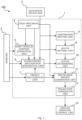
- FIG. 1 is a configuration diagram of the travel support system 100.
- the travel support system 100 includes at least a travel support device 1 as a controller, sensors 2, a navigation device map 3, and a vehicle behavior control unit 13.
- the sensors 2 detect information on a surrounding environment of the host vehicle.
- the surrounding environment includes other vehicles, pedestrians, facilities around roads, and the like.
- the sensors 2 include cameras, radars, a light detection and ranging (LIDAR), and the like mounted on a vehicle.
- the cameras capture images of surroundings of the host vehicle and output the captured images as image data.
- a plurality of cameras is mounted in order to capture images of the front side, the side, and the rear side of the host vehicle.
- the radars output, as radar information, reflected waves with respect to electromagnetic waves emitted toward the surroundings of the host vehicle.
- a plurality of radars is mounted in the same manner as the cameras.
- the LIDAR estimates a three-dimensional position of a reflection point based on the reflected waves of the lasers emitted from the host vehicle in all directions, and outputs the estimated three-dimensional position as three-dimensional position information.
- the cameras, the radars, and the LIDAR known ones can be used as the cameras, the radars, and the LIDAR.
- the navigation device map 3 is map information stored in a navigation device that receives position information (latitude and longitude) from an artificial satellite.
- the map information is not limited to being stored in a main body of the navigation device, and may be stored in an external storage device capable of communicating with the navigation device.
- the artificial satellite referred to herein is, for example, a global positioning system (GPS) satellite, a global navigation satellite system (GLONASS) satellite, and a quasi-zenith satellite.
- the travel support device 1 and the vehicle behavior control unit 13 are constituted by a microcomputer equipped with a central processing unit (CPU), a read-only memory (ROM), a random-access memory (RAM), and the like. In addition, it is also possible to configure each of the travel support device 1 and the vehicle behavior control unit 13 with a plurality of microcomputers.
- CPU central processing unit
- ROM read-only memory
- RAM random-access memory
- the travel support device 1 reads the output information of the sensors 2 and the navigation device map 3, and executes the following processing.
- a host vehicle position estimation unit 5 estimates a specific current position of the host vehicle by matching a current position of the host vehicle received by the navigation device with a high-precision map 4.
- the high-precision map 4 may be stored in advance in the travel support device 1, or may be stored in an external storage device capable of communicating with the travel support device 1.
- the high-precision map 4 has a higher accuracy of position than the navigation device map 3. Further, the navigation device map 3 does not have detailed information on a travel lane of a road, but the high-precision map 4 has detailed information on the travel lane.
- the host vehicle position estimation unit 5 identifies the current position by using the image information of the cameras.
- An object recognition unit 7 determines whether a detected object is a vehicle, a pedestrian, or another object, and further determines directions of travel thereof based on the information detected by the sensors 2.
- a surrounding recognition integration unit 6 matches the estimated position of the host vehicle, the information detected by the sensors 2, and the information recognized by the object recognition unit 7 with the high-precision map 4 and the navigation device map 3, thereby generating data indicating the current position of the host vehicle, what is around the host vehicle, and where it is around the host vehicle.
- the surrounding recognition integration unit 6 can rewrite the data if the surrounding environment changes during traveling.
- a destination setting unit 8 sets a destination input by an operator on the navigation device map 3.
- a route setting unit 9 sets a travel route on the navigation device map 3 from the current position of the host vehicle to the destination.
- An action determining unit 10 sets a plurality of control determining points on the travel route based on the travel route to the destination and information from the surrounding recognition integration unit 6 and the object recognition unit 7, and determines whether to run or stop at each of the control determining points.
- the travel route to the destination and the information from the surrounding recognition integration unit 6 and the object recognition unit 7 are also referred to as travel situation information.
- the travel situation includes a situation on a road structure, such as a stop line or a temporary stop, in addition to a situation where the host vehicle intersects with a cross-point or another vehicle.
- the setting of the control determining points and the determination of run/stop will be described hereinafter.
- other actions such as run and stop may be added and determined (for example, slow down).
- the travelable region generation unit 11 determines a region in which the host vehicle can travel based on the information from the high-precision map 4, the surrounding recognition integration unit 6, and the object recognition unit 7. Specifically, it is determined which lane in which the host vehicle travels and at which position in the travel lane the host vehicle is traveling. For example, when a bicycle is traveling in front of the travel lane in which the host vehicle is currently traveling, a travel position is set such that an appropriate distance can be secured between the host vehicle and the bicycle at a time of overtaking. In addition, if there is a parked vehicle in front of the currently traveling lane, it is determined whether the parked vehicle can be avoided while the host vehicle is kept in the currently traveling lane or it is necessary to change the lane.
- a trajectory generation unit 12 generates a travel trajectory of the host vehicle (hereinafter, this travel trajectory is also referred to as a first route) based on the set travel route to the destination, the result of determination by the action determining unit 10, and a travelable region determined by the travelable region generation unit 11.
- the travel trajectory herein includes a vehicle speed profile in addition to a trajectory relating to a position such as where the lane change is performed and where the host vehicle starts or stops on the travel route to the destination. For example, when there is a curve on the travel route, the vehicle speed profile is set such that the host vehicle decelerates in front of the curve and accelerates after passing through the curve.
- the travel trajectory generated as described above is output as data from the travel support device 1 to the vehicle behavior control unit 13.
- the vehicle behavior control unit 13 controls a driving source, a braking device, a steering device, and the like of the vehicle based on the travel trajectory.
- the action determining unit 10 extracts an event that needs to determine whether to run or stop on the first route (hereinafter, also referred to as a determining necessary event).
- the determining necessary event is a matter, an event or a situation such as an event in which traffic lights are installed, an event in which the host vehicle passes through an intersection with a second route that is a route of another vehicle or a pedestrian, an event in which the host vehicle enters the second route from the first route, an event in which the host vehicle passes another vehicle, and the like.
- the event can be expressed as a place where the host vehicle encounters the matter, or the like. Therefore, in this embodiment, the event may be specified by position information.
- the action determining unit 10 plots a plurality of extracted determining necessary events on the first route, and sets the control determining points before the determining necessary events.
- the control determining points can be set at the time when the travel route to the destination is set.
- the action determining unit 10 determines whether to run or stop at the control determining points.
- the vehicle behavior control unit 13 causes the host vehicle to run or stop at the control determining points according to a determination result. For example, when the determining necessary events are installation locations of the traffic lights, the control determining points are set in front of the traffic lights, and whether to run or stop is determined in front of the control determining points based on the image information from the cameras. In addition, the information on the traffic lights may be acquired by road-to-vehicle communication. In addition, when the determining necessary events are a temporary stop line, the control determining points are set before the temporary stop line, and the host vehicle is stopped at the control determining points based on the image information from the cameras.
- the vehicle travels without providing a control determining point, the vehicle travels while acquiring and processing all pieces of information that can be acquired, sets a stop position after recognizing that there are traffic lights ahead, and determines whether to run or stop according to states of the traffic lights.
- the stop position of the host vehicle is determined according to a surrounding situation including movement of another vehicle, so it is necessary to recalculate the stop position of the host vehicle according to the situation. Therefore, a new stop position is calculated every time the surrounding situation changes. Furthermore, it is necessary to determine the stop position based on a control model of the vehicle.
- the stop position is also determined in advance, and thus a calculation load can be reduced as compared with the control in which the control determining point is not provided.
- FIG. 2 illustrates a situation where the host vehicle crosses an oncoming lane and passes through a cross-point.
- A is the host vehicle
- B is another vehicle
- R1 is a first route
- R2 is a second route.
- the determining necessary events are the traffic lights installed at the cross-point, and the intersection of the first route R1 and the second route R2.
- control determining points are set at a stop line in front of the cross-point and an intersection of the first route R1 and the travel lane on which the other vehicle B travels will be examined.
- the host vehicle passes through a first control determining point CP1 set to the stop line and enters the cross-point.
- the host vehicle stops at a second control determining point CP2 set at a point at which the first route R1 and the travel lane in which the other vehicle B travels intersect with each other.
- the host vehicle passes through the second control determining point CP2.
- the first control determining point CP1 is displayed on the stop line
- the second control determining point CP2 is displayed on a center line, but this means a stop position where a front edge of the host vehicle does not cross the stop line and the center line.
- the second control determining point CP2 after passing through the first control determining point CP1, it may be necessary to change the determination for the second control determining point CP2 from run to stop. For example, this is a case where the other vehicle B, which has not been recognized until then, is recognized by approaching the second control determining point CP2 and being able to accurately detect the surrounding situation, or a case where the other vehicle B accelerates or decelerates and a positional relation between the host vehicle A and the other vehicle B changes.
- the host vehicle tries to run to the second control determining point CP2 after passing through the first control determining point CP1, but at that time, the following problem may occur.
- control determining points are set as described below.
- FIG. 3 shows an example of control determining points set in this embodiment in the same situation as in FIG. 2 .
- the control determining points (a first control determining point CP1 and a seventh control determining points CP7) are set at two points, that is, a stop line before a cross-point and a point at which a first route R1 and a center line intersect with each other, as in FIG. 2 , but in this embodiment, five control determining points of a second control determining point CP2 to a sixth control determining point CP6 are set between the first control determining point CP1 and the seventh control determining point CP7.
- an initial control determining point CP0 of control of turning at the cross-point is set before the stop line. The interval between adjacent control determining points will be described later.
- control determining points are densely set in a section from the stop line as the start position of the cross-point to an intersection of the first route R1 and the travel lane on which another vehicle B travels.
- the start position of the cross-point is set based on map information.
- control determining points are densely set in the cross-point, for example, it is possible to determine that the host vehicle travels to a third control determining point CP3 before entering the cross-point and stops after a fourth control determining point CP4, to detect the surrounding situation in a state where the host vehicle stops at the fourth control determining point CP4, and to change the determination such that the host vehicle travels to the seventh control determining point CP7.
- the determination of a fifth control determining point CP5 and the sixth control determining point CP6 may be changed to run according to a change in the surrounding situation after entering the cross-point, and the host vehicle may be stopped at the seventh control determining point CP7.
- FIG. 4 is a diagram for illustrating the control routine executed by the action determining unit 10. Hereinafter, steps will be described.
- step S100 the action determining unit 10 acquires a first route, which is a travel route of the host vehicle.
- step S110 the action determining unit 10 extracts an intersection of the first route and a second route, which is a route of another vehicle or a pedestrian, based on the map information.
- the second route is a road on which the other vehicle or the pedestrian travels or walks with priority over the host vehicle among roads on which other vehicles or pedestrians travel or walk.
- the roads on which the other vehicles or the pedestrians travel or walk in this step are roads on which the other vehicles or the pedestrians may travel or walk. That is, the process of this step is executed based on the map information without detecting specific another vehicle or pedestrian by the sensors 2.
- step S120 the action determining unit 10 sets a final control determining point in a range in which the control determining points are provided based on the extracted intersection.
- the seventh control determining point CP7 as the final control determining point is set at the intersection of a center line and a travel lane on which the other vehicle B travels before the intersection of the first route R1 and the second route R2.
- step S130 the action determining unit 10 sets the initial control determining point in the range in which the control determining points are provided.
- the initial control determining point CP0 is set.
- step S140 the action determining unit 10 sets a plurality of control determining points between the initial control determining point and the final control determining point.
- a range in which the control determining points are densely positioned is provided.
- the number of control determining points to be set is arbitrary.
- the first control determining point CP1 is set as an initial control determining point in a range that becomes dense on the stop line before the cross-point.
- the first control determining point CP1 may be set before the cross-point and may be set before the stop line.
- the first control determining point CP1 is set at the stop line in consideration of the calculation load.
- the final control determining point in the dense range is the seventh control determining point CP7.
- the intervals between the adjacent control determining points are set such that controllable ranges of the control determining points overlap each other.
- the controllable ranges are ranges of deviation from the control determining points that can be set when control is performed to stop at a position deviated from the control determining points. This is based on a premise that the action determining unit 10 can perform not only the control of stopping the host vehicle at the control determining point but also the control of stopping the host vehicle at a position X[cm] before the control determining point or at a position Y[cm] behind the control determining point.
- controllable ranges can be set arbitrarily. However, the controllable ranges on the front side and the controllable ranges on the back side do not need to be the same with respect to the control determining points. In addition, it is not necessary to set a plurality of control determining points at equal intervals in the range in which the control determining points are densely set. For example, by shortening the interval as it approaches the final control determining point, it may be easier to respond to changes in the situation after entering the cross-point.
- allowable positional deviation ranges may be set to overlap.
- the allowable positional deviation range is a range of deviation between an actually stopped position and a control determining point, which is allowable when control is performed to stop at the control determining point. For example, in a case where a vehicle is stopped on an uphill slope road or in a case where a vehicle is stopped from traveling at a low speed, the vehicle tends to stop before a control determining point, but if this is not allowed at all, the control becomes complicated. Therefore, an allowable range is provided for the positional deviation.
- the allowable degree can be set arbitrarily.
- the allowable positional deviation ranges may be arbitrarily set, but may be changed according to a magnitude of road surface resistance. For example, when it is raining, the road surface resistance decreases and a braking distance increases, and thus the allowable range behind the control determining point may be expanded.
- the action determining unit 10 determines in step S150 whether or not a distance to a control determining point ahead of a current position of the host vehicle in a traveling direction is less than a threshold value, and when a determination result is affirmative, the action determining unit 10 performs step S160, and when a determination result is negative, the action determining unit 10 repeatedly performs step S150.
- the threshold value can be set arbitrarily, the threshold value is set in consideration of information necessary for the determination of the run or stop at a control determining point, for example, a distance at which a state of the traffic lights, presence or absence of an oncoming vehicle, and the like can be detected.
- step S160 the action determining unit 10 determines, based on the information from the surrounding recognition integration unit 6, whether to start or stop at a control determining point closer than the threshold value. That is, the determination of this step is made for other vehicles or pedestrians detected by the sensors 2. For example, when the first control determining point CP1 to the seventh control determining point CP7 are closer than the threshold value in FIG. 3 , the start or stop is determined based on the state of the traffic lights, the position and vehicle speed of the other vehicle B, and the like. In addition, data generation in the surrounding recognition integration unit 6 is performed by a control routine different from this control routine.
- step S170 the action determining unit 10 outputs the determination result in step S150 to the vehicle behavior control unit 13.
- the vehicle behavior control unit 13 controls a driving source, a braking device, and a steering device based on the determination result.
- step S180 the action determining unit 10 determines whether or not the host vehicle has arrived at a destination, ends this routine if the host vehicle has arrived, and returns to step S150 if the host vehicle has not arrived.
- the action determining method described above that is, a method for determining action of the host vehicle by providing a range in which a plurality of control determining points are densely set, is applicable not only to the situation of FIG. 3 but also to other situations described below.
- FIG. 5 is a situation where a parked vehicle C is present in front of a travel lane in which the host vehicle A travels, and a lane change is performed in order to avoid the parked vehicle C.
- another vehicle B is traveling in a travel lane of a change destination, and the second route R2 of the other vehicle B has an intersection with the first route R1.
- the action determining unit 10 sets the control determining point CP0 as a start point of a lane change operation and the control determining point CP6 as an end point, and densely sets the first control determining point CP1 to the fifth control determining point CP5 between the control determining point CP0 and the control determining point CP6.
- the first control determining point CP1 which is the initial control determining point in the dense range, is a position at which steering is started.
- the fifth control determining point CP5, which is a final control determining point in the dense range, is an intersection between the travel lane of the change destination and the first route R1.
- the higher the vehicle speed in the travel lane of the change destination the farther the denser range is set from the intersection between the travel lane of the change destination and the first route R1. This is because, even when the vehicle speed decreases in the dense range, a section in which the host vehicle accelerates from the final fifth control determining point CP5 until the host vehicle enters the travel lane of the change destination is secured.
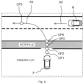
- FIG. 6 shows a situation where the host vehicle A joins a road on which the other vehicle B travels from a parking lot on a wayside. It is assumed that there is a sidewalk between the parking lot and the road.
- the action determining unit 10 sets the first control determining point CP1 as the start point of a joining operation and the fifth control determining point CP5 as the end point, and densely sets the second control determining point CP2 to the fourth control determining point CP4 between the first control determining point CP1 and the fifth control determining point CP5.
- the first control determining point CP1 to the fourth control determining point CP4 are in a dense range.
- the fourth control determining point CP4 which is the end point of the dense range, is a boundary between the sidewalk and the road.
- a control determining point is also set at a boundary between the parking lot and the sidewalk.
- the second control determining point CP2 corresponds to this control determining point.
- control determining points are set as described above, first, it is determined whether or not the host vehicle should stop before the sidewalk, and if there is a pedestrian on a route that intersects the first route R1, the host vehicle will stop at the second control determining point CP2. When there is no pedestrian or when a pedestrian passes by, the host vehicle passes through the second control determining point CP2 and the third control determining point CP3 and approaches the fourth control determining point CP4. Then, a road condition at a joining destination is detected, and it is determined whether or not to stop at the fourth control determining point CP4.
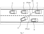
- control determining point may be added on a traveling direction side of the end point of the dense range. This will be described with reference to FIG. 7 .
- FIG. 7 is a situation of changing a lane in order to avoid a parked vehicle in front of a travel lane in which the host vehicle A travels as in FIG. 5 .
- the travel lane to be changed is congested, and a first other vehicle C to a third other vehicle E is in the vicinity of the host vehicle A.
- a final control determining point CPend is a control determining point corresponding to the fifth control determining point CP5 in FIG. 5 .
- a control determining point may be added in a case where it is difficult to make a determination with high reliability up to the fourth control determining point CP4 due to a reason such as the presence of a parked vehicle on a road.
- At least one control determining point for determining run or stop of the host vehicle is set on the first route on which the host vehicle travels by using the travel situation information, and it is determined whether to cause the host vehicle to run or stop at the control determining point before the host vehicle reaches the control determining point.
- the controller further determines, by using the travel situation information, whether or not the host vehicle enters a road on which another vehicle or a pedestrian travels or walks with priority over the host vehicle in the first route along which the host vehicle travels, and sets control determining points in a case where it is determined that the host vehicle enters the road on which the other vehicle or the pedestrian travels or walks with priority over the host vehicle more densely than in other cases.
- the travel situation information includes a situation on a road structure, such as a stop line or a temporary stop, in addition to a situation where the host vehicle intersects with a cross-point or another vehicle. Therefore, the sensors referred to here are not limited to the sensors 2, but also include those that extract map data from the Global Navigation Satellite System (GNSS) information for detecting the road structure.
- GNSS Global Navigation Satellite System
- a control determining point may be set only at a position where it is necessary to determine whether to run or stop the host vehicle on the first route. For example, in a case where a parked vehicle is present in front while the host vehicle traveling on a narrow road, and the host vehicle stops in front of the parked vehicle, or in a case where the host vehicle stops on a temporary stop line at a cross-point, the control determining point is set only at a stop position.
- the intersection between the first route and the road on which the other vehicle or the pedestrian travels or walks with priority over the host vehicle is extracted, and the control determining points are densely set based on the intersection.
- the control determining points are densely set based on the intersection.
- control determining points are densely set between the intersection of the host vehicle and the road on which the other vehicle or the pedestrian travels or walks with priority over the host vehicle. As a result, a region in which the control determining points are increased is limited, so that it is possible to suppress an unnecessary increase in the control determining points and reduce the calculation load.
- the controller sets the start point of the region in which the control determining points are densely set to the start position of the cross-point at which the first route and the road on which the other vehicle or the pedestrian travels or walks with priority over the host vehicle intersect. Accordingly, it is possible to reliably switch in a section where it may be necessary to switch the determination.
- the start position of the cross-point may be the stop line.
- the start position of the cross-point may be a predetermined distance before the crosswalk.
- the start point of the region in which the control determining points are densely set may be set to be a predetermined distance before the end point of the region.
- the controller sets the end point of the region in which the control determining points are densely set to a position at which the first route intersects with the other vehicle or the pedestrian. Accordingly, it is possible to reliably avoid contact with the other vehicle or the pedestrian.
- the intersecting position with the other vehicle or the pedestrian is an intersecting position between the first route and the travel lane in which the other vehicle travels, or an intersecting position between the first route and the crosswalk in which the pedestrian walks.
- the end point may be a point run in the traveling direction by a predetermined distance from the start point.
- the controller when the host vehicle performs a lane change to a different lane, the controller sets the start point of the region in which the control determining points are densely set as the start point of the lane change operation or the joining operation. Accordingly, it is possible to reliably switch in the section where it may be necessary to switch the determination.
- the start point may be changed according to a speed limit of a changing lane or a joining lane. In this case, the higher the speed limit, the closer the start point is.
- the start point may be changed according to road width of the changing lane or the joining lane. In this case, the smaller the road width, the closer the start point is. In either case, the fear of occupants can be alleviated. Further, the start point may be a point just before the end point by a predetermined distance.
- the controller when the host vehicle joins a road from a facility (for example, a parking lot) on a wayside, the controller provides a region for densely setting the control determining points in front of a road of a joining destination. As a result, it is possible to smoothly travel in accordance with situation change until the host vehicle joins the road.
- the controller sets the end point of the region in which the control determining points are densely set to a position at which the road of the joining destination and the first route intersect with each other. Accordingly, it is possible to reliably avoid contact with the other vehicle and the pedestrian.
- the end point may be changed according to the speed limit of the joining lane. In this case, the higher the speed limit, the closer the end point is.
- the end point may be changed according to road width of the joining lane. In this case, the smaller the road width, the closer the end point is. In either case, the fear of occupants can be alleviated.
- the end point may be a point run in the traveling direction by a predetermined distance from the start point.
- the controller sets the start point of the region in which the control determining points are densely set to a position before the position at which the travel lane of the joining destination and the first route intersect with each other or a position at which a sidewalk and the first route intersect with each other when there is the sidewalk between the facility and the road.
- the start point may be a point just before the end point by a predetermined distance.
- the start point may be set according to a blind spot when the road is viewed from the facility on the wayside. For example, when there is a parked vehicle in the travel lane on the front side in the situation of FIG. 6 and the blind spot becomes larger as the host vehicle A approaches the road, the start point is set to the front side.
- the controller sets the intervals between the control determining points in the region in which the control determining points are densely set such that the controllable ranges of the adjacent control determining points overlap each other or the allowable positional deviation ranges of the adjacent control determining points overlap each other.
- the intervals between the adjacent control determining points may be the same or different.
- the length of the controllable ranges and the length of the allowable positional deviation ranges are arbitrary values set in accordance with control accuracy of a control system. Therefore, the intervals between the control determining points can be set appropriately.
- the length of the controllable ranges and the length of the allowable positional deviation ranges may be different for each of the control determining points. Therefore, the control determining points can be appropriately arranged according to the event.
- the length of the controllable ranges and the length of the allowable positional deviation ranges may be changed according to the magnitude of the road surface resistance. Therefore, the control determining points can be appropriately arranged according to road surface conditions.
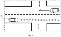
- the controller when the controller determines that the host vehicle does not enter a road on which another vehicle or a pedestrian travels or walks with priority over the host vehicle, the controller sets a control determining point only at a position where it is necessary to determine whether to run or stop the host vehicle on the first route on which the host vehicle travels by using the travel situation information. Accordingly, the number of control determining points is not unnecessarily increased, and thus the calculation load can be reduced.
- the controller when the controller determines that the host vehicle does not enter the road on which the other vehicle or the pedestrian travels or walks with priority over the host vehicle, the controller may set the control determining points at predetermined fixed intervals in the first route on which the host vehicle travels. Thereby, the number of control determining points is not unnecessarily increased, and thus the calculation load can be reduced.
- the controller when the controller determines that the host vehicle does not enter the road on which the other vehicle or the pedestrian travels or walks with priority over the host vehicle, the controller sets the control determining points according to the vehicle speed of the host vehicle such that the higher the vehicle speed, the wider the interval in the first route on which the host vehicle travels. This is because the higher the vehicle speed is, the higher the possibility that the vehicle travels straight at a constant vehicle speed is, and when the vehicle travels straight at the constant vehicle speed, a frequency of intersecting with the other vehicle or the pedestrian is low.
- control determining points are set in accordance with the vehicle speed of the host vehicle, that is, the probability of intersecting with the other vehicle or the pedestrian, it is possible to prevent the control determining points from being unnecessarily increased and to reduce the calculation load.
- a route of the host vehicle and a route of the other vehicle or the pedestrian have an intersection has been described, but it is effective to provide a range in which the control determining points are densely set even in other cases.
- the control determining points may be densely set before and after the intersection. Accordingly, when there is a change in a situation in the intersection, it is possible to flexibly respond to the change.
Landscapes
- Engineering & Computer Science (AREA)
- Automation & Control Theory (AREA)
- Transportation (AREA)
- Mechanical Engineering (AREA)
- Radar, Positioning & Navigation (AREA)
- Remote Sensing (AREA)
- Physics & Mathematics (AREA)
- General Physics & Mathematics (AREA)
- Human Computer Interaction (AREA)
- Traffic Control Systems (AREA)
Applications Claiming Priority (1)
| Application Number | Priority Date | Filing Date | Title |
|---|---|---|---|
| PCT/IB2019/000786 WO2021028708A1 (ja) | 2019-08-13 | 2019-08-13 | 車両行動決定方法及び車両行動決定装置 |
Publications (3)
| Publication Number | Publication Date |
|---|---|
| EP4016497A1 EP4016497A1 (en) | 2022-06-22 |
| EP4016497A4 EP4016497A4 (en) | 2022-09-07 |
| EP4016497B1 true EP4016497B1 (en) | 2023-05-31 |
Family
ID=74569334
Family Applications (1)
| Application Number | Title | Priority Date | Filing Date |
|---|---|---|---|
| EP19941009.3A Active EP4016497B1 (en) | 2019-08-13 | 2019-08-13 | Vehicle behavior determination method and vehicle behavior determination device |
Country Status (5)
| Country | Link |
|---|---|
| US (1) | US11535249B2 (ja) |
| EP (1) | EP4016497B1 (ja) |
| JP (1) | JP7182718B2 (ja) |
| CN (1) | CN114287026B (ja) |
| WO (1) | WO2021028708A1 (ja) |
Families Citing this family (3)
| Publication number | Priority date | Publication date | Assignee | Title |
|---|---|---|---|---|
| US11643073B2 (en) * | 2019-10-24 | 2023-05-09 | Zoox, Inc. | Trajectory modifications based on a collision zone |
| JP2022037448A (ja) * | 2020-08-25 | 2022-03-09 | スズキ株式会社 | 運転支援装置 |
| CN115662166B (zh) * | 2022-09-19 | 2024-04-09 | 长安大学 | 一种自动驾驶数据处理方法及自动驾驶交通系统 |
Family Cites Families (11)
| Publication number | Priority date | Publication date | Assignee | Title |
|---|---|---|---|---|
| JP5407764B2 (ja) * | 2009-10-30 | 2014-02-05 | トヨタ自動車株式会社 | 運転支援装置 |
| JP6180968B2 (ja) * | 2014-03-10 | 2017-08-16 | 日立オートモティブシステムズ株式会社 | 車両制御装置 |
| BR112018001073B1 (pt) | 2015-07-21 | 2023-02-14 | Nissan Motor Co., Ltd. | Dispositivo de planejamento de condução, aparelho de auxílio de deslocamento, e método para planejamento de condução |
| JP6520689B2 (ja) * | 2015-12-15 | 2019-05-29 | 株式会社デンソー | 運転支援装置 |
| RU2719080C2 (ru) * | 2016-01-22 | 2020-04-17 | Ниссан Мотор Ко., Лтд. | Способ и устройство помощи при вождении |
| JP2018041379A (ja) * | 2016-09-09 | 2018-03-15 | 本田技研工業株式会社 | 走行制御装置 |
| JP6650904B2 (ja) * | 2017-03-31 | 2020-02-19 | 本田技研工業株式会社 | 車両制御装置 |
| JP6710710B2 (ja) * | 2018-01-19 | 2020-06-17 | 本田技研工業株式会社 | 車両制御装置、車両制御方法、およびプログラム |
| JP6641583B2 (ja) * | 2018-01-31 | 2020-02-05 | 本田技研工業株式会社 | 車両制御装置、車両制御方法、およびプログラム |
| US10642275B2 (en) * | 2018-06-18 | 2020-05-05 | Zoox, Inc. | Occulsion aware planning and control |
| US10990105B2 (en) * | 2018-12-28 | 2021-04-27 | Beijing Voyager Technology Co., Ltd. | Vehicle-based virtual stop and yield line detection |
-
2019
- 2019-08-13 WO PCT/IB2019/000786 patent/WO2021028708A1/ja unknown
- 2019-08-13 US US17/634,189 patent/US11535249B2/en active Active
- 2019-08-13 EP EP19941009.3A patent/EP4016497B1/en active Active
- 2019-08-13 JP JP2021538938A patent/JP7182718B2/ja active Active
- 2019-08-13 CN CN201980099211.6A patent/CN114287026B/zh active Active
Also Published As
| Publication number | Publication date |
|---|---|
| US11535249B2 (en) | 2022-12-27 |
| WO2021028708A1 (ja) | 2021-02-18 |
| JP7182718B2 (ja) | 2022-12-02 |
| CN114287026A (zh) | 2022-04-05 |
| EP4016497A4 (en) | 2022-09-07 |
| US20220355793A1 (en) | 2022-11-10 |
| CN114287026B (zh) | 2023-03-21 |
| EP4016497A1 (en) | 2022-06-22 |
| JPWO2021028708A1 (ja) | 2021-02-18 |
Similar Documents
| Publication | Publication Date | Title |
|---|---|---|
| US11203343B2 (en) | Vehicle control device, vehicle control method, and storage medium | |
| US11225249B2 (en) | Vehicle control device, vehicle control method, and storage medium | |
| US11247692B2 (en) | Prediction device, prediction method, and storage medium | |
| US11167761B2 (en) | Vehicle control device, vehicle control method, and storage medium | |
| CN110662683B (zh) | 驾驶辅助装置以及驾驶辅助方法 | |
| RU2760241C1 (ru) | Способ помощи при вождении и устройство управления транспортным средством | |
| CN109835344B (zh) | 车辆控制装置、车辆控制方法及存储介质 | |
| EP4016497B1 (en) | Vehicle behavior determination method and vehicle behavior determination device | |
| CN110271542B (zh) | 车辆控制装置、车辆控制方法及存储介质 | |
| CN114761301B (zh) | 车辆控制方法及车辆控制装置 | |
| US20190283741A1 (en) | Vehicle control device, vehicle control method, and storage medium | |
| US11230289B2 (en) | Vehicle control device, vehicle control method, and storage medium | |
| US20190276029A1 (en) | Vehicle control device, vehicle control method, and storage medium | |
| US20220063604A1 (en) | Vehicle travel control device | |
| US20200159234A1 (en) | Vehicle control device, vehicle control method, and storage medium | |
| CN111731294A (zh) | 行驶控制装置、行驶控制方法以及存储程序的存储介质 | |
| CN111587206B (zh) | 车辆控制装置、具有该车辆控制装置的车辆以及控制方法 | |
| CN114194186B (zh) | 车辆行驶控制装置 | |
| CN112810628A (zh) | 车辆控制系统 | |
| JP7145178B2 (ja) | 走行制御装置、走行制御方法およびプログラム | |
| CN111688693B (zh) | 车辆控制装置、车辆控制方法及存储介质 | |
| CN114889601A (zh) | 行驶控制装置 | |
| RU2772439C1 (ru) | Способ определения действия транспортного средства и устройство определения действия транспортного средства | |
| JP2022134536A (ja) | 車両制御装置、車両制御方法およびプログラム | |
| CN115223397B (zh) | 交通系统 |
Legal Events
| Date | Code | Title | Description |
|---|---|---|---|
| STAA | Information on the status of an ep patent application or granted ep patent |
Free format text: STATUS: THE INTERNATIONAL PUBLICATION HAS BEEN MADE |
|
| PUAI | Public reference made under article 153(3) epc to a published international application that has entered the european phase |
Free format text: ORIGINAL CODE: 0009012 |
|
| STAA | Information on the status of an ep patent application or granted ep patent |
Free format text: STATUS: REQUEST FOR EXAMINATION WAS MADE |
|
| 17P | Request for examination filed |
Effective date: 20220307 |
|
| AK | Designated contracting states |
Kind code of ref document: A1 Designated state(s): AL AT BE BG CH CY CZ DE DK EE ES FI FR GB GR HR HU IE IS IT LI LT LU LV MC MK MT NL NO PL PT RO RS SE SI SK SM TR |
|
| A4 | Supplementary search report drawn up and despatched |
Effective date: 20220809 |
|
| RIC1 | Information provided on ipc code assigned before grant |
Ipc: B60W 60/00 20200101ALI20220803BHEP Ipc: B60W 50/00 20060101ALI20220803BHEP Ipc: B60W 30/095 20120101ALI20220803BHEP Ipc: G01C 21/26 20060101ALI20220803BHEP Ipc: G08G 1/16 20060101AFI20220803BHEP |
|
| DAV | Request for validation of the european patent (deleted) | ||
| DAX | Request for extension of the european patent (deleted) | ||
| GRAP | Despatch of communication of intention to grant a patent |
Free format text: ORIGINAL CODE: EPIDOSNIGR1 |
|
| STAA | Information on the status of an ep patent application or granted ep patent |
Free format text: STATUS: GRANT OF PATENT IS INTENDED |
|
| INTG | Intention to grant announced |
Effective date: 20221208 |
|
| GRAS | Grant fee paid |
Free format text: ORIGINAL CODE: EPIDOSNIGR3 |
|
| GRAA | (expected) grant |
Free format text: ORIGINAL CODE: 0009210 |
|
| STAA | Information on the status of an ep patent application or granted ep patent |
Free format text: STATUS: THE PATENT HAS BEEN GRANTED |
|
| AK | Designated contracting states |
Kind code of ref document: B1 Designated state(s): AL AT BE BG CH CY CZ DE DK EE ES FI FR GB GR HR HU IE IS IT LI LT LU LV MC MK MT NL NO PL PT RO RS SE SI SK SM TR |
|
| REG | Reference to a national code |
Ref country code: GB Ref legal event code: FG4D Ref country code: CH Ref legal event code: EP |
|
| REG | Reference to a national code |
Ref country code: AT Ref legal event code: REF Ref document number: 1571420 Country of ref document: AT Kind code of ref document: T Effective date: 20230615 Ref country code: DE Ref legal event code: R096 Ref document number: 602019029674 Country of ref document: DE |
|
| REG | Reference to a national code |
Ref country code: IE Ref legal event code: FG4D |
|
| REG | Reference to a national code |
Ref country code: LT Ref legal event code: MG9D |
|
| REG | Reference to a national code |
Ref country code: NL Ref legal event code: MP Effective date: 20230531 |
|
| REG | Reference to a national code |
Ref country code: AT Ref legal event code: MK05 Ref document number: 1571420 Country of ref document: AT Kind code of ref document: T Effective date: 20230531 |
|
| PG25 | Lapsed in a contracting state [announced via postgrant information from national office to epo] |
Ref country code: SE Free format text: LAPSE BECAUSE OF FAILURE TO SUBMIT A TRANSLATION OF THE DESCRIPTION OR TO PAY THE FEE WITHIN THE PRESCRIBED TIME-LIMIT Effective date: 20230531 Ref country code: NO Free format text: LAPSE BECAUSE OF FAILURE TO SUBMIT A TRANSLATION OF THE DESCRIPTION OR TO PAY THE FEE WITHIN THE PRESCRIBED TIME-LIMIT Effective date: 20230831 Ref country code: ES Free format text: LAPSE BECAUSE OF FAILURE TO SUBMIT A TRANSLATION OF THE DESCRIPTION OR TO PAY THE FEE WITHIN THE PRESCRIBED TIME-LIMIT Effective date: 20230531 Ref country code: AT Free format text: LAPSE BECAUSE OF FAILURE TO SUBMIT A TRANSLATION OF THE DESCRIPTION OR TO PAY THE FEE WITHIN THE PRESCRIBED TIME-LIMIT Effective date: 20230531 |
|
| PGFP | Annual fee paid to national office [announced via postgrant information from national office to epo] |
Ref country code: GB Payment date: 20230824 Year of fee payment: 5 |
|
| PG25 | Lapsed in a contracting state [announced via postgrant information from national office to epo] |
Ref country code: RS Free format text: LAPSE BECAUSE OF FAILURE TO SUBMIT A TRANSLATION OF THE DESCRIPTION OR TO PAY THE FEE WITHIN THE PRESCRIBED TIME-LIMIT Effective date: 20230531 Ref country code: PL Free format text: LAPSE BECAUSE OF FAILURE TO SUBMIT A TRANSLATION OF THE DESCRIPTION OR TO PAY THE FEE WITHIN THE PRESCRIBED TIME-LIMIT Effective date: 20230531 Ref country code: NL Free format text: LAPSE BECAUSE OF FAILURE TO SUBMIT A TRANSLATION OF THE DESCRIPTION OR TO PAY THE FEE WITHIN THE PRESCRIBED TIME-LIMIT Effective date: 20230531 Ref country code: LV Free format text: LAPSE BECAUSE OF FAILURE TO SUBMIT A TRANSLATION OF THE DESCRIPTION OR TO PAY THE FEE WITHIN THE PRESCRIBED TIME-LIMIT Effective date: 20230531 Ref country code: LT Free format text: LAPSE BECAUSE OF FAILURE TO SUBMIT A TRANSLATION OF THE DESCRIPTION OR TO PAY THE FEE WITHIN THE PRESCRIBED TIME-LIMIT Effective date: 20230531 Ref country code: IS Free format text: LAPSE BECAUSE OF FAILURE TO SUBMIT A TRANSLATION OF THE DESCRIPTION OR TO PAY THE FEE WITHIN THE PRESCRIBED TIME-LIMIT Effective date: 20230930 Ref country code: HR Free format text: LAPSE BECAUSE OF FAILURE TO SUBMIT A TRANSLATION OF THE DESCRIPTION OR TO PAY THE FEE WITHIN THE PRESCRIBED TIME-LIMIT Effective date: 20230531 Ref country code: GR Free format text: LAPSE BECAUSE OF FAILURE TO SUBMIT A TRANSLATION OF THE DESCRIPTION OR TO PAY THE FEE WITHIN THE PRESCRIBED TIME-LIMIT Effective date: 20230901 |
|
| PGFP | Annual fee paid to national office [announced via postgrant information from national office to epo] |
Ref country code: FR Payment date: 20230824 Year of fee payment: 5 Ref country code: DE Payment date: 20230830 Year of fee payment: 5 |
|
| PG25 | Lapsed in a contracting state [announced via postgrant information from national office to epo] |
Ref country code: FI Free format text: LAPSE BECAUSE OF FAILURE TO SUBMIT A TRANSLATION OF THE DESCRIPTION OR TO PAY THE FEE WITHIN THE PRESCRIBED TIME-LIMIT Effective date: 20230531 |
|
| PG25 | Lapsed in a contracting state [announced via postgrant information from national office to epo] |
Ref country code: SK Free format text: LAPSE BECAUSE OF FAILURE TO SUBMIT A TRANSLATION OF THE DESCRIPTION OR TO PAY THE FEE WITHIN THE PRESCRIBED TIME-LIMIT Effective date: 20230531 |
|
| PG25 | Lapsed in a contracting state [announced via postgrant information from national office to epo] |
Ref country code: SM Free format text: LAPSE BECAUSE OF FAILURE TO SUBMIT A TRANSLATION OF THE DESCRIPTION OR TO PAY THE FEE WITHIN THE PRESCRIBED TIME-LIMIT Effective date: 20230531 Ref country code: SK Free format text: LAPSE BECAUSE OF FAILURE TO SUBMIT A TRANSLATION OF THE DESCRIPTION OR TO PAY THE FEE WITHIN THE PRESCRIBED TIME-LIMIT Effective date: 20230531 Ref country code: RO Free format text: LAPSE BECAUSE OF FAILURE TO SUBMIT A TRANSLATION OF THE DESCRIPTION OR TO PAY THE FEE WITHIN THE PRESCRIBED TIME-LIMIT Effective date: 20230531 Ref country code: PT Free format text: LAPSE BECAUSE OF FAILURE TO SUBMIT A TRANSLATION OF THE DESCRIPTION OR TO PAY THE FEE WITHIN THE PRESCRIBED TIME-LIMIT Effective date: 20231002 Ref country code: EE Free format text: LAPSE BECAUSE OF FAILURE TO SUBMIT A TRANSLATION OF THE DESCRIPTION OR TO PAY THE FEE WITHIN THE PRESCRIBED TIME-LIMIT Effective date: 20230531 Ref country code: DK Free format text: LAPSE BECAUSE OF FAILURE TO SUBMIT A TRANSLATION OF THE DESCRIPTION OR TO PAY THE FEE WITHIN THE PRESCRIBED TIME-LIMIT Effective date: 20230531 Ref country code: CZ Free format text: LAPSE BECAUSE OF FAILURE TO SUBMIT A TRANSLATION OF THE DESCRIPTION OR TO PAY THE FEE WITHIN THE PRESCRIBED TIME-LIMIT Effective date: 20230531 |
|
| REG | Reference to a national code |
Ref country code: DE Ref legal event code: R097 Ref document number: 602019029674 Country of ref document: DE |
|
| PG25 | Lapsed in a contracting state [announced via postgrant information from national office to epo] |
Ref country code: MC Free format text: LAPSE BECAUSE OF FAILURE TO SUBMIT A TRANSLATION OF THE DESCRIPTION OR TO PAY THE FEE WITHIN THE PRESCRIBED TIME-LIMIT Effective date: 20230531 |
|
| REG | Reference to a national code |
Ref country code: CH Ref legal event code: PL |
|
| PG25 | Lapsed in a contracting state [announced via postgrant information from national office to epo] |
Ref country code: MC Free format text: LAPSE BECAUSE OF FAILURE TO SUBMIT A TRANSLATION OF THE DESCRIPTION OR TO PAY THE FEE WITHIN THE PRESCRIBED TIME-LIMIT Effective date: 20230531 |
|
| PLBE | No opposition filed within time limit |
Free format text: ORIGINAL CODE: 0009261 |
|
| STAA | Information on the status of an ep patent application or granted ep patent |
Free format text: STATUS: NO OPPOSITION FILED WITHIN TIME LIMIT |
|
| PG25 | Lapsed in a contracting state [announced via postgrant information from national office to epo] |
Ref country code: LU Free format text: LAPSE BECAUSE OF NON-PAYMENT OF DUE FEES Effective date: 20230813 |
|
| PG25 | Lapsed in a contracting state [announced via postgrant information from national office to epo] |
Ref country code: LU Free format text: LAPSE BECAUSE OF NON-PAYMENT OF DUE FEES Effective date: 20230813 Ref country code: CH Free format text: LAPSE BECAUSE OF NON-PAYMENT OF DUE FEES Effective date: 20230831 |
|
| PG25 | Lapsed in a contracting state [announced via postgrant information from national office to epo] |
Ref country code: SI Free format text: LAPSE BECAUSE OF FAILURE TO SUBMIT A TRANSLATION OF THE DESCRIPTION OR TO PAY THE FEE WITHIN THE PRESCRIBED TIME-LIMIT Effective date: 20230531 |
|
| REG | Reference to a national code |
Ref country code: BE Ref legal event code: MM Effective date: 20230831 |
|
| 26N | No opposition filed |
Effective date: 20240301 |
|
| REG | Reference to a national code |
Ref country code: IE Ref legal event code: MM4A |