EP4015835B1 - Lüfteradapter für einen motor - Google Patents
Lüfteradapter für einen motor Download PDFInfo
- Publication number
- EP4015835B1 EP4015835B1 EP21209436.1A EP21209436A EP4015835B1 EP 4015835 B1 EP4015835 B1 EP 4015835B1 EP 21209436 A EP21209436 A EP 21209436A EP 4015835 B1 EP4015835 B1 EP 4015835B1
- Authority
- EP
- European Patent Office
- Prior art keywords
- fan
- coupling
- base
- engine
- adapter
- Prior art date
- Legal status (The legal status is an assumption and is not a legal conclusion. Google has not performed a legal analysis and makes no representation as to the accuracy of the status listed.)
- Active
Links
Images



Classifications
-
- F—MECHANICAL ENGINEERING; LIGHTING; HEATING; WEAPONS; BLASTING
- F01—MACHINES OR ENGINES IN GENERAL; ENGINE PLANTS IN GENERAL; STEAM ENGINES
- F01P—COOLING OF MACHINES OR ENGINES IN GENERAL; COOLING OF INTERNAL-COMBUSTION ENGINES
- F01P5/00—Pumping cooling-air or liquid coolants
- F01P5/02—Pumping cooling-air; Arrangements of cooling-air pumps, e.g. fans or blowers
- F01P5/04—Pump-driving arrangements
-
- F—MECHANICAL ENGINEERING; LIGHTING; HEATING; WEAPONS; BLASTING
- F01—MACHINES OR ENGINES IN GENERAL; ENGINE PLANTS IN GENERAL; STEAM ENGINES
- F01P—COOLING OF MACHINES OR ENGINES IN GENERAL; COOLING OF INTERNAL-COMBUSTION ENGINES
- F01P11/00—Component parts, details, or accessories not provided for in, or of interest apart from, groups F01P1/00 - F01P9/00
-
- F—MECHANICAL ENGINEERING; LIGHTING; HEATING; WEAPONS; BLASTING
- F04—POSITIVE - DISPLACEMENT MACHINES FOR LIQUIDS; PUMPS FOR LIQUIDS OR ELASTIC FLUIDS
- F04D—NON-POSITIVE-DISPLACEMENT PUMPS
- F04D25/00—Pumping installations or systems
- F04D25/02—Units comprising pumps and their driving means
-
- F—MECHANICAL ENGINEERING; LIGHTING; HEATING; WEAPONS; BLASTING
- F04—POSITIVE - DISPLACEMENT MACHINES FOR LIQUIDS; PUMPS FOR LIQUIDS OR ELASTIC FLUIDS
- F04D—NON-POSITIVE-DISPLACEMENT PUMPS
- F04D29/00—Details, component parts, or accessories
- F04D29/26—Rotors specially for elastic fluids
- F04D29/263—Rotors specially for elastic fluids mounting fan or blower rotors on shafts
-
- F—MECHANICAL ENGINEERING; LIGHTING; HEATING; WEAPONS; BLASTING
- F16—ENGINEERING ELEMENTS AND UNITS; GENERAL MEASURES FOR PRODUCING AND MAINTAINING EFFECTIVE FUNCTIONING OF MACHINES OR INSTALLATIONS; THERMAL INSULATION IN GENERAL
- F16D—COUPLINGS FOR TRANSMITTING ROTATION; CLUTCHES; BRAKES
- F16D1/00—Couplings for rigidly connecting two coaxial shafts or other movable machine elements
- F16D1/06—Couplings for rigidly connecting two coaxial shafts or other movable machine elements for attachment of a member on a shaft or on a shaft-end
- F16D1/076—Couplings for rigidly connecting two coaxial shafts or other movable machine elements for attachment of a member on a shaft or on a shaft-end by clamping together two faces perpendicular to the axis of rotation, e.g. with bolted flanges
-
- H—ELECTRICITY
- H02—GENERATION; CONVERSION OR DISTRIBUTION OF ELECTRIC POWER
- H02K—DYNAMO-ELECTRIC MACHINES
- H02K7/00—Arrangements for handling mechanical energy structurally associated with dynamo-electric machines, e.g. structural association with mechanical driving motors or auxiliary dynamo-electric machines
- H02K7/14—Structural association with mechanical loads, e.g. with hand-held machine tools or fans
-
- F—MECHANICAL ENGINEERING; LIGHTING; HEATING; WEAPONS; BLASTING
- F01—MACHINES OR ENGINES IN GENERAL; ENGINE PLANTS IN GENERAL; STEAM ENGINES
- F01P—COOLING OF MACHINES OR ENGINES IN GENERAL; COOLING OF INTERNAL-COMBUSTION ENGINES
- F01P5/00—Pumping cooling-air or liquid coolants
- F01P5/02—Pumping cooling-air; Arrangements of cooling-air pumps, e.g. fans or blowers
- F01P5/04—Pump-driving arrangements
- F01P2005/046—Pump-driving arrangements with electrical pump drive
-
- F—MECHANICAL ENGINEERING; LIGHTING; HEATING; WEAPONS; BLASTING
- F01—MACHINES OR ENGINES IN GENERAL; ENGINE PLANTS IN GENERAL; STEAM ENGINES
- F01P—COOLING OF MACHINES OR ENGINES IN GENERAL; COOLING OF INTERNAL-COMBUSTION ENGINES
- F01P2070/00—Details
- F01P2070/50—Details mounting fans to heat-exchangers
-
- F—MECHANICAL ENGINEERING; LIGHTING; HEATING; WEAPONS; BLASTING
- F05—INDEXING SCHEMES RELATING TO ENGINES OR PUMPS IN VARIOUS SUBCLASSES OF CLASSES F01-F04
- F05D—INDEXING SCHEME FOR ASPECTS RELATING TO NON-POSITIVE-DISPLACEMENT MACHINES OR ENGINES, GAS-TURBINES OR JET-PROPULSION PLANTS
- F05D2260/00—Function
- F05D2260/30—Retaining components in desired mutual position
- F05D2260/36—Retaining components in desired mutual position by a form fit connection, e.g. by interlocking
Definitions
- the present disclosure relates generally to a fan adapter for an engine, and more particularly, to a two-piece fan adapter for an engine.
- Engine-driven machines typically utilize one or more fans coupled to, or otherwise in proximity to, the engine to help cool the engine.
- the fan is coupled to the engine, for example, via an adapter coupled to a hub or other portion of the engine, and the fan may be driven by a crankshaft, a dedicated fan drive, an auxiliary shaft, etc.
- the adapter often includes a base end to be coupled to the hub or other portion of the engine and a fan end, for example, to be coupled to the fan.
- different sizes of engines may require different sizes or types of fans, and/or different spacings between the hub or coupling portion of the engine and the fan.
- adapters may include smaller distances between the base end and the fan end, which may increase the difficulty and/or complexity of coupling the adaptor and/or fan to the engine. For example, a smaller distance between the base end and the fan end may increase the difficulty in fitting coupling elements (e.g., bolts, screws, etc.) between the base end and the fan end to couple the adapter to the hub or other portion of the engine.
- coupling elements e.g., bolts, screws, etc.
- the '948 patent discloses an adapter for attaching a cooling fan to a motor in a cooling fan module for an automotive cooling system.
- the adapter of the '948 patent includes first and second parts to form a two-piece fan adapter, but the coupling of the first and second parts relies on a shaft of the driving motor.
- the first part of the fan adapter is preassembled with a portion of the rotor, which may require specific sizes and/or shapes of both the first and second parts relative to the shaft of the driving motor.
- the coupling of the first and second parts of the fan adapter may not secure the respective orientations of the first and second parts to each other, may be susceptible to shear, and/or may otherwise increase the risk of breakage. While the adapter of the '948 patent may be suitable for some applications, the adapter may not be suitable for other applications.
- the disclosed fan adapters of the present disclosure may solve one or more of the problems set forth above and/or other problems in the art. The scope of the current disclosure, however, is defined by the attached claims, and not by the ability to solve any specific problem.
- US5938405 A describes a fan adapter according to the preamble of claim 1.
- the apparatus comprises a spacer body with the base and a shaft extending therefrom having a reduced perimeter section over which the fan hub mounts. Engagement rods are inserted in the fan hub to retain the fan hub on the shaft.
- a fan adapter as defined in claim 1 is provided.
- FIG. 1 illustrates a perspective view of an exemplary fan adapter 10, according to the present disclosure.
- fan adapter 10 may be used to couple a fan (e.g., an engine cooling fan), a fan impeller, or one or more fan blades to a rotational drive portion of an engine (not shown).
- Fan adapter 10 includes a base portion or first portion 12, and a fan end portion or second portion 14.
- adapter 10 may be configured to rotationally couple a fan, for example, a cooling fan, to a drive portion of an engine, for example, to a drive pulley or to a fan drive.
- first portion 12 may be directly coupled to the drive portion (e.g., a drive pulley) of an engine ( FIGs.
- first portion 12 and second portion 14 are fixedly coupled to each other (e.g., directly coupled), and first portion 12 may be configured to be coupled to a fan drive pulley or a fan drive of the engine.
- the fan drive pulley or the fan drive may be belt driven, hydraulically driven, etc.
- fan adapter 10 fixedly couples a rotating or drive element of the engine to the fan such that rotation of the drive element of the engine (e.g., the fan drive pulley or fan drive) rotates fan adapter 10 and the fan, for example, to help cool the engine.
- first portion 12 and second portion 14 may be removably coupled via one or more coupling mechanisms, for example, a screw or a bolt 16.
- first portion 12 may be coupled to the engine, and then second portion 14 may be coupled to first portion 12.
- one or more dowel rods 18 and/or one or more washers 20 may also help couple first portion 12 and second portion 14.
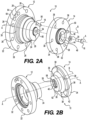
- First portion 12 includes a mounting portion 22 and a coupling portion 24.
- Mounting portion 22 may be substantially cylindrical, and may be configured to be coupled (e.g., directly coupled) to a portion of the engine (e.g., the fan drive pulley or the fan drive), for example, via one or more mounting elements ( FIGs. 4A and 4B ), for example, screws, bolts, etc., through a plurality of mounting holes 26.
- Mounting holes 26 may be circumferentially spaced around mounting portion 22, for example, evenly or unevenly.
- Coupling portion 24 may be a substantially cylindrical extension from mounting portion 22, for example, along axis A ( FIGs 2A and 2B ) and toward second portion 14. As shown in FIGs.
- mounting portion 22 of first portion 12 may be larger (e.g., in diameter relative to axis A) than coupling portion 24 of first portion 12.
- Coupling portion 24 may also include a mating portion 28 ( FIG. 2A ).
- Mating portion 28 may be sized and/or shaped to be mated to (e.g., coupled to via an at least partially overlapping or interlocking engagement) a corresponding portion of second portion 14.
- first portion 12 may include one or more graduated surfaces 30, for example, graduated annular surfaces, on coupling portion 24 between mounting portion 22 and mating portion 28.
- first portion 12 may include a cavity 32, for example, in a central portion within mounting portion 22, which may help couple first portion 12 to the drive portion or element of the engine.
- Second portion 14 includes a mounting portion 34 and a coupling portion 36.
- Mounting portion 34 may be substantially cylindrical, and may be configured to be coupled to a portion of the fan, for example, via one or more mounting elements (not shown), for example, screws, bolts, etc., through a plurality of mounting holes 38.
- Mounting holes 38 may be circumferentially spaced around mounting portion 22, for example, evenly or unevenly.
- Coupling portion 36 may be a substantially cylindrical extension from mounting portion 34, for example, along axis A ( FIGs. 2A and 2B ) and toward first portion 12. As shown in FIGs. 2A and 2B , mounting portion 34 of second portion 14 may be larger (e.g., in diameter relative to axis A) than coupling portion 36 of second portion 14.
- Coupling portion 36 may also include a mating portion 40 ( FIG. 2B ).
- Mating portion 40 may be sized and/or shaped to be mated to (e.g., directly coupled to via an at least partially overlapping or interlocking engagement) a corresponding portion (e.g., projection 60) of first portion 12.
- second portion 14 may include one or more transition surfaces 42, for example, one or more slanted, curved, or angled portions on coupling portion 36 between mounting portion 34 and mating portion 40.
- second portion 14 may include a mounting extension 44 and a cavity 46, for example, in a central portion within mounting portion 34, which may help couple second portion 14 to the fan.
- first portion 12 and second portion 14 may be coupled via bolt 16, dowel rod 18, and washer 20.
- second portion 14 includes a through-hole 50, for example, extending along axis A, through a central portion of second portion 14. Through-hole 50 may be machined through the central portion of second portion 14. At least a portion of bolt 16 may be threaded. Through-hole 50 may be threaded, or may be smooth.
- Bolt 16, for example, with washer 20 surrounding a portion of bolt 16, may be inserted (either threaded or slid) through through-hole 50.
- second portion 14 may include one or more abutment surfaces 52 to abut and/or block washer 20. As shown in FIG.
- a portion of bolt 16 may then be received within a hole 54 in mating portion 28 of first portion 12.
- Hole 54 may be at least partially threaded, and may be machined in mating portion 28, for example, along a central axis of mating portion 28 (e.g., coaxial with axis A). In this manner, tightening bolt 16 into hole 54 may help to couple second portion 14 to first portion 12.
- mating portion 28 of first portion 12 may include a dowel rod hole 56
- mating portion 40 of second portion 14 may also include a dowel rod hole 58
- Dowel rod hole 56 may be a blind hole extending through a portion of first portion 12
- dowel rod hole 58 may be a blind hole extending through a portion of second portion 14.
- Dowel rod holes 56 and 58 may be machined and/or drilled out of respective portions of first portion 12 and second portion 14.
- Dowel rod holes 56 and 58 may be smooth holes, or may be at least partially threaded or roughened, which may help retain dowel rod 18 within dowel rod holes 56 and 58.
- Dowel rod holes 56 and 58 may be spaced away from and unaligned with central axis A, for example, along axis B.
- dowel rod hole 56 may be positioned the same distance from axis A in first portion 12 as dowel rod hole 58 is positioned in second portion 14.
- Dowel rod 18 may be positioned within dowel holes 56 and 58 during the coupling of first portion 12 and second portion 14.
- Dowel rod 18 may help to couple first portion 12 and second portion 14, for example, by helping to prevent relative rotation, which may loosen bolt 16.
- Dowel rod 18 may also help to protect fan adapter 10 against and/or reduce shear forces between first portion 12 and second portion 14, which otherwise may loosen bolt 16 and/or damage fan adapter 10.
- more than one bolt 16 and/or more than one dowel rod 18, and corresponding holes through portions of first portion 12 and second portion 14 may be used to couple first portion 12 and second portion 14 and help protect against relative rotation and/or reduce shear forces.
- mating portion 28 of first portion 12 and mating portion 40 of second portion 14 may have corresponding shapes.
- mating portion 28 may include a projection 60, for example, a circular or cylindrical projection.
- Projection 60 may include a one or more graduated surfaces, and/or one or more rounded or curved surfaces, which may help couple mating portion 28 of first portion 12 to mating portion 40 of second portion 14.
- mating portion 40 of second portion 14 may include a recess 62, for example, a circular or cylindrical recess.
- Recess 62 may include one or more graduated surfaces, and/or one or more rounded or curved surfaces, which may help couple mating portion 28 of first portion 12 to mating portion 40 of second portion 14.
- at least a portion of projection 60 may be received within recess 62 when first portion 12 and second portion 14 are coupled together.
- the portion of projection 60 being received within recess 62 forms axial contact between projection 60 and recess 62, which may help stabilize and/or retain the coupling between first portion 12 and second portion 14.
- first portion 12 and second portion 14 in abutting contact (e.g., via surfaces of coupling portion 24 of first portion 12 and coupling portion 36 of second portion 14), but projection 60 extends into recess 62 in mating portion 40 to increase the surface area of the engagement between first portion 12 and second portion 14.
- Projection 60 extending into recess 62 may also help the user align first portion 12 and second portion 14, for example, during assembly of fan adaptor 10.
- One or more of projection 60 and/or recess 62 may be machined out of first portion 12 or second portion 14. It is noted that, although not shown, mating portion 28 of first portion 12 may include a recess, and mating portion 40 of second portion 14 may include a projection.
- first portion 12 or second portion 14 may be formed via casting.
- one or more of first portion 12 or second portion 14 may include one or more balance holes 64 (shown in first portion 12), which may be formed via machining (e.g., drilling) after the casting in order to balance the casted element.
- the location of balance holes 64 may be determined by dynamically balancing the casted element.
- one or more of first portion 12 or second portion 14 may be formed by machine from bar stock.
- first portion 12 may be cast (and balanced), and second portion 14 may be machined from bar stock.
- both first portion 12 and second portion 14 may be formed via separate castings, or both first portion 12 and second portion 14 may be separately formed via machining from bar stock.
- first portion 12 and second portion 14 may be formed of steel, aluminum, or another appropriate material.
- different formation techniques and/or materials may be more cost effective and/or efficient.
- different formation techniques and/or materials may be more expensive, but may yield a stronger or more durable element.
- FIGs. 3A and 3B illustrate views of a fan adapter 10 (not covered by the claims), with similar elements of fan adapter 10 shown by 100 added to the reference numbers.
- a fan adapter 110 includes a first portion 112 and a second portion 114.
- first portion 112 may be coupled to a portion of an engine via one or more mounting elements extending through one or more mounting hole(s) 126 in a mounting portion 122.
- first portion 112 includes a coupling portion 124 with a mating portion 128, which may be coupled to a mating portion 140 of a coupling portion 136 of second portion 112, and a bolt 116 and a washer 120 may help secure first portion 112 and second portion 114, as discussed above.
- Second portion 114 may include a mounting portion 134, which may include a plurality of mounting holes 138. Furthermore, one or more of first portion 112 or second portion 114 may include one or more balancing holes 164 (shown in first portion 112).
- coupling portion 124 and 136 may include mating portions 128 and 140 with non-circular shapes or configurations (which is not according to the invention).
- mating portion 128 may include a projection 160 that is rectangular or square
- mating portion 140 may include a recess 162 that is rectangular or square.
- mating portions 128 and 140 may help to couple first portion 112 and second portion 114, for example, by helping to prevent relative rotation, which may loosen bolt 116.
- Non-circular mating portions 128 and 140 may also help to protect fan adapter 110 against shear forces between first portion 112 and second portion 114, which otherwise may loosen bolt 116 and/or damage fan adapter 110.
- fan adapter 110 may also include one or more dowel rods and dowel rod holes in coupling portions 124 and 136.
- mating portion 128 and mating portion 140 may include other non-circular shapes or configurations.
- mating portions 128 and 140 may include triangular shapes, pentagonal shapes, hexagonal shapes, etc.
- mating portions 128 and 140 may include trapezoidal shapes, star shapes, or irregular shapes.
- FIGs. 4A and 4B illustrate views of an alternative example of a fan adapter according to the present disclosure, with similar elements of fan adapter 10 shown by 200 added to the reference numbers.
- a fan adapter 210 includes a first portion 212 and a second portion 214.
- FIG. 4A shows a schematic view of an engine 200 and a fan 202 coupled together via fan adapter 210 (i.e., first portion 212 and second portion 214), and
- FIG. 4B shows a schematic view of engine 200, fan 202, and fan adapter 210 uncoupled. It is noted that FIGs. 4A and 4B are not to scale.
- first portion 212 may be directly coupled to a rotating or drive element 208 (e.g., a drive shaft, a fan drive pulley, a fan drive, etc.) of engine 200 via one or more mounting elements 204 extending through one or more mounting hole(s) (not shown) in a mounting portion 222 of first portion 212.
- drive element 208 may include one or more mounting holes that correspond to the mounting holes in mounting portion 222 of first portion 212 such that one or more mounting elements 204 may extend through one or more portions of mounting portion 222 and into one or more portions of drive element 208.
- first portion 212 includes a coupling portion 224, which may be directly coupled to a coupling portion 236 of second portion 214, as discussed above.
- first portion 212 includes a coupling portion 224, which may be directly coupled to a coupling portion 236 of second portion 214, as discussed above.
- Second portion 214 may be directly coupled to a portion of fan 202 via one or more mounting elements 206 extending through one or more mounting hole(s) (not shown) in a mounting portion 234 of second portion 214.
- fan 202 may include one or more mounting holes that correspond to the mounting holes in mounting portion 234 of second portion 214 such that one or more mounting elements 206 may extend through one or more portions of mounting portion 234 and into one or more portions of fan 202.
- fan adapter 210 rotationally couples drive element 208 of engine 200 to fan 202 such that rotation of drive element 208 of engine 200 (e.g., the fan drive) rotates fan adapter 210 and fan 202, for example, to help cool engine 200.
- first portion 212 and second portion 214 when coupled together, first portion 212 and second portion 214 may be spaced apart by a distance X.
- Distance X may be a distance between mounting portion 222 of first portion 212 and mounting portion 234 of second portion 214. In some embodiments discussed herein, distance X may be a standard distance between first portion 212 and second portion 214, even if different first portions 212 and second portions 214 are used to couple fan 202 to engine 200. Alternatively, distance X may vary depending on the size and/or shape of a selected first portion 212 and/or the size and/or shape of a selected second portion 214. In either aspect, as shown in FIG. 4B , one or more mounting elements 204 may include a distance, or length, Y.
- Distance Y may be greater than distance X.
- the one or more mounting elements 204 that couple first portion 212 to engine 200 are not limited in length and may be longer than distance X between mounting portion 222 of first portion 212 and mounting portion 234 of second portion 214 when fan adapter 210 is assembled. Accordingly, the user may use mounting elements 204 that are longer than distance X when coupling first portion 212 of fan adapter 210 to engine 200.
- fan adapter 10 may be used in any machine that includes an engine that includes requires cooling and/or air circulation.
- Fan adapter 10 described herein may provide a durable and versatile connection to couple a fan to the engine, with a limited number of components, easier and/or faster installation, and/or easier and/or faster access for maintenance or replacement. Therefore, the disclosed fan adapter 10 may be reliable and low cost, without sacrificing performance.
- first portion 12 may be a predetermined size and/or shape.
- First portion 12 may be coupled to the engine, for example, during assembly, before shipment, after shipment, etc.
- one or more mounting elements e.g., one or more bolts 16
- first portion 12 may be extended through mounting hole(s) 26 to couple first portion 12 to the engine (e.g., to a fan pulley or to a fan drive).
- second portion 14 may be coupled to first portion 12, for example, via bolt 16, dowel rod 18, and washer 20. In this aspect, second portion 14 does not interfere with the initial mounting of first portion 12 on the engine.
- the one or more mounting elements that couple first portion 12 to the engine are not limited in length and may be longer than the distance between mounting portion 22 of first portion 12 and mounting portion 34 of second portion 14 when fan adapter 10 is assembled.
- the final spacing between mounting portion 22 and mounting portion 34 does not limit the length of the one or more mounting elements that couple first portion 12 to the engine, or otherwise interfere with the coupling of first portion 12 to the engine.
- dowel rod 18 may help to couple first portion 12 and second portion 14, for example, by helping to prevent relative rotation, which may loosen bolt 16.
- dowel rod 18 may also help to protect fan adapter 10 against and/or reduce shear forces between first portion 12 and second portion 14, which otherwise may loosen bolt 16 and/or damage fan adapter 10.
- the non-circular mating portion configuration as shown in FIGs. 3A and 3B and discussed above, may also help to prevent relative rotation between first portion 112 and second portion 114, while also helping to protect fan adapter 110 against and/or reduce shear forces between first portion 112 and second portion 114.
- first portion 12 may be coupled to first portion 12, for example, to couple different types, sizes, etc. of fans to the engine.
- coupling portion 24 of first portion 12 and coupling portion 36 of second portion 14 may be a standard shape and size (e.g., "commonized"), but different second portions 14 may include mounting portions 34 that are sized and/or shaped for different sizes, types, etc. of fans.
- first portion 12 may be configured to be coupled to a variety of engines, and depending on the type and/or size of the engine, a different second portion 14 (and a different fan) may be coupled to first portion 12.
- mounting portion 34 when one second portion 14 is mounted to first portion 12, mounting portion 34 may be spaced from mounting portion 22 of first portion 12 by a first spacing. Then, when another second portion 14 is mounted to first portion 12, mounting portion 34 of the another second portion 14 may be spaced from mounting portion 22 of first portion 12 by a second spacing.
- different second portions 14 may include larger or smaller mounting portions 34, and/or other different sizes, shapes, features, etc. in order for different sizes, types, etc. of fans to be coupled to second portion 14, and thus to the engine.
- the coupling portions 24 of the different first portions 12 and the coupling portions 36 of the second portion 14 may be standard shapes and sizes, the different first portions 12 and the different second portions 14 may be coupled together, for example, to couple any type and/or size of fan to any type and/or size of engine.
- different first portions 12 may include mounting portions 22 that are sized and/or shaped for different sizes, types, etc. of engines.
- different second portions 14 may include mounting portions 34 that are sized and/or shaped for different sizes, types, etc. of fans.
- different first portions 12 and/or different second portions 14 may include similar mounting portions 22, 34, but may include different coupling portions 24 or 36 (e.g., longer longitudinal lengths).
- first portion 12 may be a standard size and/or shape, for example, that is common to all or most engines, and second portions 14 may include different sizes and/or shapes for different sizes, types, etc. of fans.
- the selected first portion 12 and/or second portion 14 may not only correspond to the selected engine and/or the selected fan, but also may correspond to the desired spacing between the selected engine and the selected fan.
- a different first portion 12 may be coupled to the engine.
- a user may have an inventory or supply of a plurality of engines of different sizes, types, etc., and may also have an inventory or supply of a plurality of different first portions 12 of different sizes, shapes, etc.
- the user may select one of the plurality of engines (e.g., based on the type of machine, desired implementation, etc.), and may then select one of the plurality of different first portions 12 based on the selected engine (and/or a desired spacing between the selected engine and a fan).
- the selected first portion 12 may be coupled to the selected engine, as discussed herein.
- a different second portion 14 may be coupled to the fan and to first portion 12.
- a user may have an inventory or supply of a plurality of fans of different sizes, types, etc., and may also have an inventory or supply of a plurality of different second portions 14 of different sizes, shapes, etc.
- the user may select one of the plurality of fans (e.g., based on the selected engine, desired implementation, etc.), and may then select one of the plurality of different second portions 14 based on the selected fan (and/or the desired spacing between the selected engine and the selected fan).
- the selected second portion 14 may be coupled to the selected fan and to the selected first portion 12, as discussed herein, for example, with coupling portion 24 of the selected first portion 12 being coupled to coupling portion 36 of the selected second portion 14.
- One or more of the plurality of engine, the plurality of first portions 12, the plurality of second portions 14, and/or the plurality of fans may be grouped as a kit, a system, etc.
- the commonality and interchangeability of first portion 12 and second portions 14 of fan adapter 10 may allow for different fans to be coupled to different engines, and may also help to provide for easier, simpler, and/or less time-consuming assembly of the selected fan to the selected engine.
- This commonality and interchangeability may also help to provide for easier, simpler, and/or less time-consuming disassembly (e.g., by removing bolt 16 and, if applicable, dowel rod 18) in order to couple a different second portion 14, inspect, repair, and/or replace the fan, etc.
- various aspects discussed herein may help to reduce material costs, as one type of first portion 12 (or different types of first portions 12) may be used with different types of second portions 14 and different types of fans.
Landscapes
- Engineering & Computer Science (AREA)
- General Engineering & Computer Science (AREA)
- Mechanical Engineering (AREA)
- Chemical & Material Sciences (AREA)
- Combustion & Propulsion (AREA)
- Power Engineering (AREA)
- Structures Of Non-Positive Displacement Pumps (AREA)
Claims (3)
- Lüfteradapter (10), umfassend:ein Unterteil (12), das einen Montageabschnitt (22) und einen Kopplungsabschnitt (24) einschließt, wobei das Unterteil (12) konfiguriert ist, um mit einem Abschnitt eines Motors gekoppelt zu werden; undeinen Lüfterendabschnitt (14), wobei der Lüfterendabschnitt (14) einen Montageabschnitt (34) und einen Kopplungsabschnitt (36) einschließt,wobei der Kopplungsabschnitt (36) des Lüfterendabschnitts (14) konfiguriert ist, um mit dem Kopplungsabschnitt (24) des Unterteils (12) gekoppelt zu werden, und wobei der Lüfterendabschnitt (14) über ein oder mehrere Kopplungselemente (16, 18, 20) lösbar mit dem Unterteil (12) koppelbar ist, um eine relative Drehung zwischen dem Unterteil (12) und dem Lüfterendabschnitt (14) zu verhindern, wobei das eine oder die mehreren Kopplungselemente (16, 18, 20) eine Schraube (16) und einen Dübelstab (18) umfassen;das Unterteil (12) konfiguriert ist, um mit einer Lüfterantriebsscheibe oder einem Lüfterantrieb gekoppelt zu werden, und wobei die Kopplungsabschnitte (24, 36) des Unterteils (12) und des Lüfterendabschnitts (14) komplementäre Gegenabschnitte (28, 40) einschließen;wobei der Gegenabschnitt (28) des Unterteils (12) eine Steckerkonfiguration einschließt und wobei der Gegenabschnitt (40) des Lüfterendabschnitts (14) eine Buchsenkonfiguration einschließt;dadurch gekennzeichnet, dass ein radial mittlerer Abschnitt des Lüfterendabschnitts (14) ein Durchgangsloch (50) einschließt, das zum Aufnehmen eines Abschnitts der Schraube (16) konfiguriert ist, und wobei ein radial mittlerer Abschnitt des Kopplungsabschnitts (24) des Unterteils (12) ein Gewindesackloch (54) einschließt, das zum Aufnehmen eines weiteren Abschnitts der Schraube (16) konfiguriert ist, um den Lüfterendabschnitt (14) mit dem Unterteil (12) zu koppeln, wobei der Kopplungsabschnitt (36) des Lüfterendabschnitts (14) ein Sackloch (58) einschließt, das zum Aufnehmen eines Abschnitts des Dübelstabs (18) konfiguriert ist, und wobei das Unterteil (12) ein weiteres Sackloch (56) einschließt, das zum Aufnehmen eines weiteren Abschnitts des Dübelstabs (18) konfiguriert ist.
- Lüfteradapter (10) nach Anspruch 1, wobei der Gegenabschnitt (28) des Unterteils (12) eine kreisförmige Steckerkonfiguration einschließt und wobei der Gegenabschnitt (40) des Lüfterendabschnitts (14) eine kreisförmige Buchsenkonfiguration einschließt.
- Lüfteradapter (10) nach Anspruch 1, wobei der Montageabschnitt (22) des Unterteils (12) im Durchmesser relativ zu einer Längsachse (A) des Lüfteradapters (10) größer als der Kopplungsabschnitt (24) des Unterteils (12) ist und wobei der Montageabschnitt (34) des Lüfterendabschnitts (14) im Durchmesser relativ zu der Längsachse (A) des Lüfteradapters größer als der Kopplungsabschnitt (36) des Lüfterendabschnitts (14) ist.
Applications Claiming Priority (1)
| Application Number | Priority Date | Filing Date | Title |
|---|---|---|---|
| US17/122,411 US11377998B1 (en) | 2020-12-15 | 2020-12-15 | Fan adapter for an engine |
Publications (2)
| Publication Number | Publication Date |
|---|---|
| EP4015835A1 EP4015835A1 (de) | 2022-06-22 |
| EP4015835B1 true EP4015835B1 (de) | 2025-05-28 |
Family
ID=78725252
Family Applications (1)
| Application Number | Title | Priority Date | Filing Date |
|---|---|---|---|
| EP21209436.1A Active EP4015835B1 (de) | 2020-12-15 | 2021-11-19 | Lüfteradapter für einen motor |
Country Status (3)
| Country | Link |
|---|---|
| US (1) | US11377998B1 (de) |
| EP (1) | EP4015835B1 (de) |
| CN (1) | CN114635780A (de) |
Family Cites Families (17)
| Publication number | Priority date | Publication date | Assignee | Title |
|---|---|---|---|---|
| US3824807A (en) | 1972-11-09 | 1974-07-23 | J Hecht | Engine cooling fan spacer structure |
| US4180024A (en) * | 1978-06-28 | 1979-12-25 | Fredrico Hernandez | Internal combustion engine fan adapter |
| US4692053A (en) * | 1986-03-24 | 1987-09-08 | Manuel Sampedro | Direct drive fan coupling assembly |
| US5667045A (en) * | 1995-09-18 | 1997-09-16 | Rockford Powertrain, Inc. | Continuously variable fan drive clutch arrangement |
| US5938405A (en) | 1998-03-06 | 1999-08-17 | Coleman Machine, Inc. | Quick release engine cooling fan shaft |
| US7165514B2 (en) * | 2004-10-06 | 2007-01-23 | Deere & Company | Variable speed fan drive |
| US7104382B2 (en) * | 2004-10-21 | 2006-09-12 | Kit Masters Inc. | Clutch system |
| US20080295786A1 (en) * | 2007-06-04 | 2008-12-04 | Darren James Nelson | Variable speed fan drive |
| US9624817B2 (en) | 2012-03-09 | 2017-04-18 | Brose Fahrzeugteile GmbH & Co. Kommanditgesellschaft, Würzburg | Cooling fan module and adapter device therefor |
| WO2014027619A1 (ja) * | 2012-08-16 | 2014-02-20 | 日立建機株式会社 | 建設機械の冷却ファン取付構造 |
| US20140102432A1 (en) * | 2012-10-16 | 2014-04-17 | Diamond Products, Limited | Cooling System For Concrete Saw |
| US20140271285A1 (en) * | 2013-03-15 | 2014-09-18 | Eugene McDougall | Low energy magnetic spa circulation system |
| US9874214B2 (en) * | 2014-01-28 | 2018-01-23 | 4Front Engineered Solutions, Inc. | Fan with fan blade mounting structure |
| US20150308334A1 (en) * | 2015-07-07 | 2015-10-29 | Caterpillar Inc. | Driveline assembly for radiator fan drive |
| US20180298913A1 (en) * | 2017-04-12 | 2018-10-18 | Jerry Savage | Direct Drive Radiator Cooling Fan Hub |
| US10907527B2 (en) * | 2018-06-06 | 2021-02-02 | Champion Power Equipment, Inc. | Standby generator alternator adapter with engine cooling air intake |
| CN211975145U (zh) * | 2019-12-31 | 2020-11-20 | 潍柴动力股份有限公司 | 一种发动机散热连接盘和散热结构 |
-
2020
- 2020-12-15 US US17/122,411 patent/US11377998B1/en active Active
-
2021
- 2021-11-19 EP EP21209436.1A patent/EP4015835B1/de active Active
- 2021-12-06 CN CN202111478506.XA patent/CN114635780A/zh active Pending
Also Published As
| Publication number | Publication date |
|---|---|
| US11377998B1 (en) | 2022-07-05 |
| US20220186654A1 (en) | 2022-06-16 |
| CN114635780A (zh) | 2022-06-17 |
| EP4015835A1 (de) | 2022-06-22 |
Similar Documents
| Publication | Publication Date | Title |
|---|---|---|
| EP1715735B1 (de) | Stumpfrodegerät | |
| EP3323192B1 (de) | Anordnung zum abstimmen eines generators | |
| EP4015791B1 (de) | Adaptersysteme für motorlüfter und verfahren | |
| EP0701064A1 (de) | Lüfter und Lüfterantrieb; Verfahren zur Montage dafür | |
| US4610600A (en) | Adjustable-pitch axial fan wheel | |
| JP2002195195A (ja) | ガスタービン用の取り替え可能な可変ステータ羽根 | |
| US11377998B1 (en) | Fan adapter for an engine | |
| US6578674B2 (en) | Converter arrangement for modular motor | |
| EP1416164A2 (de) | Geformter Lüfter in zwei Teiler | |
| KR19990068025A (ko) | 핀미러커터의 부착기구 | |
| US6681898B1 (en) | Coupling arrangement for coupling a motor to a hoist machine | |
| WO2000020781A1 (en) | V-belt pulley | |
| JP2004132439A (ja) | 動力伝達装置及びその組立方法 | |
| KR100822582B1 (ko) | 팬 밸런스 교정구조 | |
| RU2239731C2 (ru) | Легкосъемное крепежное соединение с радиальным натягом | |
| JP2018202934A (ja) | パワーユニットの製造方法及びその製造方法に用いる組付け治具 | |
| EP1050683A2 (de) | Lüfternabe | |
| JP2001253203A (ja) | ハブユニット | |
| US20240413703A1 (en) | Method and apparatus of axial fastening for rotating electric machines | |
| CN218958641U (zh) | 安装件、定子及电动工具 | |
| CN219388220U (zh) | 一种多级离心泵的轴头定位轴套结构 | |
| KR101389331B1 (ko) | 시로코 팬 | |
| CN221416282U (zh) | 一种磨床砂轮快速拆装夹具 | |
| HK40110792A (en) | An axial fan and methods of manufacturing axial fan blades and assembling the fan | |
| JPH06284622A (ja) | 回転電機 |
Legal Events
| Date | Code | Title | Description |
|---|---|---|---|
| PUAI | Public reference made under article 153(3) epc to a published international application that has entered the european phase |
Free format text: ORIGINAL CODE: 0009012 |
|
| STAA | Information on the status of an ep patent application or granted ep patent |
Free format text: STATUS: THE APPLICATION HAS BEEN PUBLISHED |
|
| AK | Designated contracting states |
Kind code of ref document: A1 Designated state(s): AL AT BE BG CH CY CZ DE DK EE ES FI FR GB GR HR HU IE IS IT LI LT LU LV MC MK MT NL NO PL PT RO RS SE SI SK SM TR |
|
| STAA | Information on the status of an ep patent application or granted ep patent |
Free format text: STATUS: REQUEST FOR EXAMINATION WAS MADE |
|
| 17P | Request for examination filed |
Effective date: 20221215 |
|
| RBV | Designated contracting states (corrected) |
Designated state(s): AL AT BE BG CH CY CZ DE DK EE ES FI FR GB GR HR HU IE IS IT LI LT LU LV MC MK MT NL NO PL PT RO RS SE SI SK SM TR |
|
| STAA | Information on the status of an ep patent application or granted ep patent |
Free format text: STATUS: EXAMINATION IS IN PROGRESS |
|
| 17Q | First examination report despatched |
Effective date: 20240318 |
|
| GRAP | Despatch of communication of intention to grant a patent |
Free format text: ORIGINAL CODE: EPIDOSNIGR1 |
|
| STAA | Information on the status of an ep patent application or granted ep patent |
Free format text: STATUS: GRANT OF PATENT IS INTENDED |
|
| RIC1 | Information provided on ipc code assigned before grant |
Ipc: F16D 1/076 20060101ALI20241128BHEP Ipc: F04D 25/02 20060101ALI20241128BHEP Ipc: F04D 29/044 20060101ALI20241128BHEP Ipc: F01P 5/04 20060101ALI20241128BHEP Ipc: F16D 1/08 20060101ALI20241128BHEP Ipc: F04D 29/26 20060101AFI20241128BHEP |
|
| INTG | Intention to grant announced |
Effective date: 20241223 |
|
| GRAS | Grant fee paid |
Free format text: ORIGINAL CODE: EPIDOSNIGR3 |
|
| GRAA | (expected) grant |
Free format text: ORIGINAL CODE: 0009210 |
|
| STAA | Information on the status of an ep patent application or granted ep patent |
Free format text: STATUS: THE PATENT HAS BEEN GRANTED |
|
| P01 | Opt-out of the competence of the unified patent court (upc) registered |
Free format text: CASE NUMBER: APP_18574/2025 Effective date: 20250416 |
|
| AK | Designated contracting states |
Kind code of ref document: B1 Designated state(s): AL AT BE BG CH CY CZ DE DK EE ES FI FR GB GR HR HU IE IS IT LI LT LU LV MC MK MT NL NO PL PT RO RS SE SI SK SM TR |
|
| REG | Reference to a national code |
Ref country code: GB Ref legal event code: FG4D |
|
| REG | Reference to a national code |
Ref country code: CH Ref legal event code: EP |
|
| REG | Reference to a national code |
Ref country code: IE Ref legal event code: FG4D Ref country code: DE Ref legal event code: R096 Ref document number: 602021031383 Country of ref document: DE |
|
| REG | Reference to a national code |
Ref country code: NL Ref legal event code: MP Effective date: 20250528 |
|
| PG25 | Lapsed in a contracting state [announced via postgrant information from national office to epo] |
Ref country code: FI Free format text: LAPSE BECAUSE OF FAILURE TO SUBMIT A TRANSLATION OF THE DESCRIPTION OR TO PAY THE FEE WITHIN THE PRESCRIBED TIME-LIMIT Effective date: 20250528 Ref country code: ES Free format text: LAPSE BECAUSE OF FAILURE TO SUBMIT A TRANSLATION OF THE DESCRIPTION OR TO PAY THE FEE WITHIN THE PRESCRIBED TIME-LIMIT Effective date: 20250528 |
|
| REG | Reference to a national code |
Ref country code: LT Ref legal event code: MG9D |
|
| PG25 | Lapsed in a contracting state [announced via postgrant information from national office to epo] |
Ref country code: GR Free format text: LAPSE BECAUSE OF FAILURE TO SUBMIT A TRANSLATION OF THE DESCRIPTION OR TO PAY THE FEE WITHIN THE PRESCRIBED TIME-LIMIT Effective date: 20250829 Ref country code: NO Free format text: LAPSE BECAUSE OF FAILURE TO SUBMIT A TRANSLATION OF THE DESCRIPTION OR TO PAY THE FEE WITHIN THE PRESCRIBED TIME-LIMIT Effective date: 20250828 |
|
| PG25 | Lapsed in a contracting state [announced via postgrant information from national office to epo] |
Ref country code: NL Free format text: LAPSE BECAUSE OF FAILURE TO SUBMIT A TRANSLATION OF THE DESCRIPTION OR TO PAY THE FEE WITHIN THE PRESCRIBED TIME-LIMIT Effective date: 20250528 Ref country code: PL Free format text: LAPSE BECAUSE OF FAILURE TO SUBMIT A TRANSLATION OF THE DESCRIPTION OR TO PAY THE FEE WITHIN THE PRESCRIBED TIME-LIMIT Effective date: 20250528 |
|
| PG25 | Lapsed in a contracting state [announced via postgrant information from national office to epo] |
Ref country code: BG Free format text: LAPSE BECAUSE OF FAILURE TO SUBMIT A TRANSLATION OF THE DESCRIPTION OR TO PAY THE FEE WITHIN THE PRESCRIBED TIME-LIMIT Effective date: 20250528 |
|
| PG25 | Lapsed in a contracting state [announced via postgrant information from national office to epo] |
Ref country code: HR Free format text: LAPSE BECAUSE OF FAILURE TO SUBMIT A TRANSLATION OF THE DESCRIPTION OR TO PAY THE FEE WITHIN THE PRESCRIBED TIME-LIMIT Effective date: 20250528 |
|
| PG25 | Lapsed in a contracting state [announced via postgrant information from national office to epo] |
Ref country code: RS Free format text: LAPSE BECAUSE OF FAILURE TO SUBMIT A TRANSLATION OF THE DESCRIPTION OR TO PAY THE FEE WITHIN THE PRESCRIBED TIME-LIMIT Effective date: 20250828 |
|
| PG25 | Lapsed in a contracting state [announced via postgrant information from national office to epo] |
Ref country code: IS Free format text: LAPSE BECAUSE OF FAILURE TO SUBMIT A TRANSLATION OF THE DESCRIPTION OR TO PAY THE FEE WITHIN THE PRESCRIBED TIME-LIMIT Effective date: 20250928 |
|
| PG25 | Lapsed in a contracting state [announced via postgrant information from national office to epo] |
Ref country code: LV Free format text: LAPSE BECAUSE OF FAILURE TO SUBMIT A TRANSLATION OF THE DESCRIPTION OR TO PAY THE FEE WITHIN THE PRESCRIBED TIME-LIMIT Effective date: 20250528 |
|
| REG | Reference to a national code |
Ref country code: AT Ref legal event code: MK05 Ref document number: 1798729 Country of ref document: AT Kind code of ref document: T Effective date: 20250528 |
|
| PGFP | Annual fee paid to national office [announced via postgrant information from national office to epo] |
Ref country code: DE Payment date: 20251022 Year of fee payment: 5 |
|
| PGFP | Annual fee paid to national office [announced via postgrant information from national office to epo] |
Ref country code: GB Payment date: 20251023 Year of fee payment: 5 |
|
| PG25 | Lapsed in a contracting state [announced via postgrant information from national office to epo] |
Ref country code: AT Free format text: LAPSE BECAUSE OF FAILURE TO SUBMIT A TRANSLATION OF THE DESCRIPTION OR TO PAY THE FEE WITHIN THE PRESCRIBED TIME-LIMIT Effective date: 20250528 Ref country code: SM Free format text: LAPSE BECAUSE OF FAILURE TO SUBMIT A TRANSLATION OF THE DESCRIPTION OR TO PAY THE FEE WITHIN THE PRESCRIBED TIME-LIMIT Effective date: 20250528 Ref country code: DK Free format text: LAPSE BECAUSE OF FAILURE TO SUBMIT A TRANSLATION OF THE DESCRIPTION OR TO PAY THE FEE WITHIN THE PRESCRIBED TIME-LIMIT Effective date: 20250528 |
|
| PGFP | Annual fee paid to national office [announced via postgrant information from national office to epo] |
Ref country code: FR Payment date: 20251023 Year of fee payment: 5 |
|
| PGFP | Annual fee paid to national office [announced via postgrant information from national office to epo] |
Ref country code: TR Payment date: 20251028 Year of fee payment: 5 |
|
| PG25 | Lapsed in a contracting state [announced via postgrant information from national office to epo] |
Ref country code: CZ Free format text: LAPSE BECAUSE OF FAILURE TO SUBMIT A TRANSLATION OF THE DESCRIPTION OR TO PAY THE FEE WITHIN THE PRESCRIBED TIME-LIMIT Effective date: 20250528 |
|
| PG25 | Lapsed in a contracting state [announced via postgrant information from national office to epo] |
Ref country code: EE Free format text: LAPSE BECAUSE OF FAILURE TO SUBMIT A TRANSLATION OF THE DESCRIPTION OR TO PAY THE FEE WITHIN THE PRESCRIBED TIME-LIMIT Effective date: 20250528 |
|
| PG25 | Lapsed in a contracting state [announced via postgrant information from national office to epo] |
Ref country code: SK Free format text: LAPSE BECAUSE OF FAILURE TO SUBMIT A TRANSLATION OF THE DESCRIPTION OR TO PAY THE FEE WITHIN THE PRESCRIBED TIME-LIMIT Effective date: 20250528 |
|
| PG25 | Lapsed in a contracting state [announced via postgrant information from national office to epo] |
Ref country code: IT Free format text: LAPSE BECAUSE OF FAILURE TO SUBMIT A TRANSLATION OF THE DESCRIPTION OR TO PAY THE FEE WITHIN THE PRESCRIBED TIME-LIMIT Effective date: 20250528 |
|
| REG | Reference to a national code |
Ref country code: DE Ref legal event code: R097 Ref document number: 602021031383 Country of ref document: DE |
|
| PG25 | Lapsed in a contracting state [announced via postgrant information from national office to epo] |
Ref country code: RO Free format text: LAPSE BECAUSE OF FAILURE TO SUBMIT A TRANSLATION OF THE DESCRIPTION OR TO PAY THE FEE WITHIN THE PRESCRIBED TIME-LIMIT Effective date: 20250528 |
|
| PLBE | No opposition filed within time limit |
Free format text: ORIGINAL CODE: 0009261 |
|
| STAA | Information on the status of an ep patent application or granted ep patent |
Free format text: STATUS: NO OPPOSITION FILED WITHIN TIME LIMIT |
|
| REG | Reference to a national code |
Ref country code: CH Ref legal event code: L10 Free format text: ST27 STATUS EVENT CODE: U-0-0-L10-L00 (AS PROVIDED BY THE NATIONAL OFFICE) Effective date: 20260409 |
|
| 26N | No opposition filed |
Effective date: 20260303 |