EP4015338A1 - Modulares komponentengerüst, wagen eines schienenfahrzeugs und verfahren zur herstellung eines wagens - Google Patents
Modulares komponentengerüst, wagen eines schienenfahrzeugs und verfahren zur herstellung eines wagens Download PDFInfo
- Publication number
- EP4015338A1 EP4015338A1 EP21215474.4A EP21215474A EP4015338A1 EP 4015338 A1 EP4015338 A1 EP 4015338A1 EP 21215474 A EP21215474 A EP 21215474A EP 4015338 A1 EP4015338 A1 EP 4015338A1
- Authority
- EP
- European Patent Office
- Prior art keywords
- module
- framework
- modular component
- car
- carriage
- Prior art date
- Legal status (The legal status is an assumption and is not a legal conclusion. Google has not performed a legal analysis and makes no representation as to the accuracy of the status listed.)
- Granted
Links
Images




Classifications
-
- B—PERFORMING OPERATIONS; TRANSPORTING
- B61—RAILWAYS
- B61D—BODY DETAILS OR KINDS OF RAILWAY VEHICLES
- B61D17/00—Construction details of vehicle bodies
- B61D17/04—Construction details of vehicle bodies with bodies of metal; with composite, e.g. metal and wood body structures
- B61D17/043—Construction details of vehicle bodies with bodies of metal; with composite, e.g. metal and wood body structures connections between superstructure sub-units
- B61D17/045—The sub-units being construction modules
-
- B—PERFORMING OPERATIONS; TRANSPORTING
- B61—RAILWAYS
- B61L—GUIDING RAILWAY TRAFFIC; ENSURING THE SAFETY OF RAILWAY TRAFFIC
- B61L15/00—Indicators provided on the vehicle or train for signalling purposes
- B61L15/0045—Destination indicators, identification panels or distinguishing signs on the vehicles
-
- Y—GENERAL TAGGING OF NEW TECHNOLOGICAL DEVELOPMENTS; GENERAL TAGGING OF CROSS-SECTIONAL TECHNOLOGIES SPANNING OVER SEVERAL SECTIONS OF THE IPC; TECHNICAL SUBJECTS COVERED BY FORMER USPC CROSS-REFERENCE ART COLLECTIONS [XRACs] AND DIGESTS
- Y02—TECHNOLOGIES OR APPLICATIONS FOR MITIGATION OR ADAPTATION AGAINST CLIMATE CHANGE
- Y02T—CLIMATE CHANGE MITIGATION TECHNOLOGIES RELATED TO TRANSPORTATION
- Y02T30/00—Transportation of goods or passengers via railways, e.g. energy recovery or reducing air resistance
Definitions
- the invention relates to a modular component framework for arrangement in the carriage of a rail vehicle, a carriage of a rail vehicle and a method for producing such a carriage.
- the publication discloses such an assembly unit with a support which can be fastened inside the car body structure in an area below the car body roof. Furthermore, the assembly unit comprises at least one supply line, which is preassembled on the carrier, and a plurality of supply devices or functional assemblies connected to the supply line, which are preassembled on the carrier.
- the publication also discloses a method for producing a rail vehicle using an assembly unit designed in this way, in which a car body structure of the rail vehicle is provided and the carrier is fastened inside the car body structure in an area below the car body roof.
- different rail vehicles can each include vehicle-specific carriages which, for example, can have different lengths from one another. It is also known that different functionalities are to be provided in different rail vehicles or their wagons.
- the technical problem therefore arises of creating a modular component framework for arrangement in a carriage of a rail vehicle, a carriage of a rail vehicle and a method for producing such a carriage, which enable simple, cost-effective production of such a carriage, while at the same time car-specific requirements in can be easily fulfilled.
- a modular component framework for arrangement in a carriage of a rail vehicle is proposed.
- the component framework serves to arrange, in particular to fasten, components of the carriage of the rail vehicle and can therefore also be referred to as a component carrier.
- Components can be elements, in particular functional elements, of the wagon or rail vehicle.
- components also include connecting elements, e.g. for establishing an electrical or fluid-technical connection.
- a connection element can be an electrical wire.
- the modular component framework includes a framework module.
- the component framework comprises at least one further framework module.
- the modular component structure thus comprises at least two modules, but preferably more than two, in particular three, four or five modules.
- a module of the module set can be mechanically and/or electrically and/or fluidically connected to at least one other module.
- At least one skeleton module of the module set can have or form fastening means or interfaces for fastening to a car body of the car.
- Such framework modules can be mechanically connected to the car body, for example using mounting brackets or other mechanical connection methods, e.g. using a screw connection.
- the framework modules can be arranged in a ceiling area of the car body and fastened there.
- a framework module can be used to accommodate at least one electrical line.
- a module can include or form a line duct, which can also be referred to as a cable duct.
- An electrical line can serve as a line for supplying energy to an electrical or electronic component of the car.
- an electrical line can be used for signal transmission, for example of control signals or other signals, to such a component or from such a component.
- a module can have or form means for guiding the at least one electrical line.
- a module can also have or form means for fastening the at least one electrical line.
- Such guiding and/or fastening means can be designed, for example, as cable clamps, cable holders or other cable routing elements. It is possible for such guiding and/or fastening means to be detachably fastened to the module.
- the guiding means (and optionally the fastening means) can be configured in such a way that a line routing is made possible in such a way that predetermined EMC criteria are met.
- a framework module can comprise an electrical line or a multiplicity of electrical lines, for example in the form of a cable harness or cable bundle.
- the at least one electrical line, in particular the cable harness or line bundle, of a framework module can have a module-specific length.
- the line or lines can also be guided by means of guidance, for example so that a desired course is provided.
- a course of the electrical line(s) according to a predetermined circuit diagram can be provided by such a framework module.
- a desired connection (wiring) between different elements, in particular functional elements, of the framework module can also be provided by such a framework module.
- a module can include or form at least one air-conditioning duct.
- Such an air conditioning duct can be used to guide a fluid flow, in particular an air flow, this fluid flow being used to set a desired temperature in the carriage of the rail vehicle, in particular in an interior.
- a module can include or form installation space for electrical connection elements and/or fluid-technical connection elements.
- the installation space can provide the fluid-technical connection elements.
- the module can include elements that can control a fluid inlet or fluid outlet, in particular a volume flow rate.
- the module can include elements for fluid guidance.
- a module it is also possible for a module to have or form an empty channel that can be used for the subsequent arrangement of, for example, additional electrical lines.
- a module it is possible for a module to comprise two, in particular at least or exactly two, line ducts for electrical lines and at least one, in particular exactly one, air conditioning duct, with the air conditioning duct being arranged between the two receiving ducts.
- the air conditioning duct can be arranged along a transverse direction of the car between the two receiving ducts. In this case, it is possible that at least a portion of the air conditioning duct is arranged at the same height as the two accommodation ducts along a car vertical direction.
- a module can include at least two, in particular exactly two, air-conditioning ducts and at least one, in particular exactly one, line duct for electrical lines, with the receiving duct being arranged between the two air-conditioning ducts.
- the receiving duct can be arranged between the two air-conditioning ducts along the transverse direction of the car, with at least one section of the receiving duct being arranged at the same height as the two air-conditioning ducts along the vertical direction of the car.
- a longitudinal direction of the carriage can be oriented parallel to a longitudinal axis of the carriage, which can also be referred to as the rolling axis of the carriage.
- a vertical direction of the car can be oriented parallel to a vertical axis of the car, which can also be referred to as the car's yaw axis or car's vertical axis. This can be opposite to the direction of a gravitational force, in particular of a Car bottom to a car top, be oriented.
- the transverse direction of the car can be oriented parallel to a transverse axis of the car, which can be a pitch axis of the car, for example. This in turn can be oriented perpendicular to the longitudinal axis of the car and the vertical axis of the car explained.
- a first framework module is a functional module.
- the functional module within the meaning of this disclosure designates a module with a component or a (functional) element that provides a desired, ie predetermined, functionality.
- a functionality can be provided if a module or at least one component of the module can perform at least one predetermined function.
- Such a functional module can thus also provide installation space for the at least one functional element.
- a module it is possible for a module to provide the installation space for arranging the elements and lines explained. If the module is a functional module, it is also possible for the module to include a functional element.
- a module includes both a functional element and an electrical line
- the functional element can be connected to the electrical line.
- the electrical line is arranged in a line duct of the functional module, a connecting section of the electrical line can be routed from the functional element to/into the line duct.
- the cable duct can have corresponding openings for this purpose. It is possible that the function module provides the connection section or this connection section can be designed and arranged separately from the function module.
- the first framework module is a wagon-unspecific standard module. This can mean that the properties of the framework module, e.g. a dimension and/or the functionality provided by the module, are specified in a way that is not specific to the car.
- a standard module can be a module in a set of several standard modules that are different from one another. Such standard modules can have different properties from one another. In particular, these standard modules can have predetermined dimensions that differ from one another, in particular lengths, and/or can provide predetermined functionalities that differ from one another.
- the modules in a set of several standard modules that are different from one another include at least one electrical line, for example in the form of a cable harness or line bundle
- electrical lines from different modules can have different module-specific lengths from one another.
- different standard modules of the same length can each include at least one electrical line, for example in the form of a cable harness or line bundle, with the electrical lines of different modules having different module-specific lengths from one another.
- the at least one electrical line of different modules can have or form the same interfaces for connection, for example connections formed as plug connectors.
- a wagon-unspecific standard module can also designate a module that can be installed in different wagons of a rail vehicle or in wagons of different rail vehicles, in particular without an adjustment/change in the dimensions and/or the functionality(s) provided.
- a wagon-unspecific standard module can in particular be a reusable module. This can mean that a module used in a car is removed from the car and installed in a different car for further use. It is particularly possible here for the framework module to be reused without changing the number and/or position of the elements of the framework module.
- the elements of the framework module and/or a circuit diagram provided by the framework module and/or an electrical connection of different elements and/or parts of the mechanical construction or the mechanical construction of the framework module provided by the framework module can be reused.
- a bundle of cables from the framework module for example, can also be reused.
- properties of the standard module that is not specific to a car are fixed in a way that is not specific to a rail vehicle or car, ie is not adapted to a specific car or a specific rail vehicle.
- Such a module can thus also be used to provide a wiring diagram that is not specific to a vehicle, and an electrical connection that is not specific to a vehicle, of various elements of the module.
- the at least one further framework module is a vehicle-specific framework module. This can mean that at least one property of the scaffolding module is specified for the specific vehicle.
- a length of the further framework module can be specified in a vehicle-specific manner. In this case, a length refers to a dimension along the longitudinal axis explained above.
- the additional framework module specific to the vehicle cannot be a functional module.
- the module cannot include a functional element that is explained in more detail below.
- the further module it is also possible for the further module to be a functional module.
- the car-specific, further framework module can be a dummy module or extension module.
- a module cannot include an electrical line, in particular in the form of a cable harness or line bundle.
- the extension module can have or form means for guiding at least one electrical line.
- a module can also have or form means for fastening the at least one electrical line.
- an extension module it is possible for an extension module to include a functional element.
- the extension module it is also possible for the extension module not to include a functional element.
- the proposed modular component structure advantageously results in simple production of a rail vehicle carriage (and thus also of a rail vehicle with several such carriages), in particular simple production of carriages of different rail vehicles or of different carriages of a rail vehicle.
- at least one standard module that is not specific to the vehicle can be used to produce the component framework.
- the car-specific adaptation of the modular component framework can then take place through the production and further use of a car-specific framework module.
- the length of the component framework can be easily adapted to the length, in particular the installation length, of the carriage.
- At least one standard module that is not specific to the vehicle and at least one extension module to be used, with the standard module comprising at least one electrical line, in particular in the form of a cable harness or line bundle, with the length of the at least one electrical line of the standard module being selected in such a way that a section of the electrical line of the standard module is placed in the extension module after the modules have been attached to one another.
- the at least one electrical line can be rolled out into the extension module.
- the at least one electrical line can then be arranged there in the desired manner and, if necessary, also fastened.
- the length of the at least one electrical line of a standard module can be longer than an installation length provided by the standard module for the electrical line.
- the length of the at least one electrical line can correspond to the installation length provided by the carriage for the component framework.
- first carriage has a first length and another carriage has an additional length that is shorter than the first length, it is therefore possible for the standard modules with the same length to be used for the production of a component framework for both carriages, with the However, electrical lines of these standard modules have different lengths.
- a standard module with an electrical line that has a first length can be used to produce a component framework for the first carriage.
- a standard module with an electrical lead having a second length that is shorter than the first length can be used to produce a component framework for the second carriage.
- the standard modules of the same length can be used for different cars, but which can include short or long cable harnesses.
- an extension module can be used to produce the component framework for the first carriage or to produce the component framework for both carriages, in which extension module the electrical line of the standard module is then arranged.
- longer electrical lines of a standard module can offer flexibility for use in longer cars.
- the production effort for producing the component framework in a carriage of a rail vehicle and also the production costs for the carriage can be minimized.
- a functional module comprises at least one functional element and at least one control element for controlling the functional element.
- a functional element can in particular be a light source, for example a light band for illuminating an interior of the car.
- a functional element can also be a loudspeaker, a display device, for example a screen, a heating device, a cooling device or a ventilation device, e.g. in the form of a fan.
- a functional element can also be an image capture device, for example for capturing a (part of) the car interior or a (part of) the car exterior. The enumeration of functional elements is exemplary and not exhaustive.
- the functional module includes a functional element, this can be fastened in the module, for example via a suitable holding device of the module.
- a control element for controlling the functional element can in particular be a control device, e.g. in the form of a microcontroller or an integrated circuit.
- the control element can also be attached to the module.
- a functional module can include a supply element for supplying energy to the functional element and/or the control element.
- a supply element can, for example, be an energy storage device, for example a battery or an accumulator.
- a supply element can also be a current or voltage converter, for example a DC/DC converter, an AC/DC converter or a DC/AC converter.
- a supply element can also be a transformer.
- a function module may include at least one safety element, for example a current safety element, ie an electrical fuse.
- the securing element can also be attached to the module.
- the various elements of a functional module can be electrically connected to one another in a predetermined, desired manner. It is also possible for at least one of the elements to be connected via electrical connection means of the function module to interfaces of the module and/or connections of the module that are explained in more detail below.
- the arrangement of the functional element and the at least one control element for controlling the functional element in the functional module advantageously results in a decentralization of the elements required to provide a desired functionality and that the desired functionality can be provided as independently as possible of specific requirements of external elements. This in turn simplifies the integration of the component framework into the rail vehicle and thus also the production. In particular, the length of the electrical lines used to connect the elements can be reduced since, for example, a functional element of a module does not have to be connected to a control element outside of the module.
- the first framework module is a preassembled framework module.
- the further framework module is a preassembled framework module.
- This can mean, in particular, that components of a module, in particular the elements explained above, but also the electrical lines explained above, are already attached to the module before it is installed, in particular before it is brought into the car body.
- This advantageously enables simple assembly of the components, in particular since the module is easier to access before it is introduced into the car body than in a state in which the module is already arranged in the car body.
- the pre-assembly also advantageously allows a functional test to be carried out before installation in the car body, which is essential is less complex than with an already done assembly. Furthermore, in the event of a malfunction outside the car body, a simple repair can be carried out.
- connection of the components of a module can then take place via corresponding interfaces or connections of the module. These connections or interfaces can be used in particular to produce plug-in connections between two modules or to a module.
- a framework module comprises a standardized holding device for at least one functional element or forms this holding device.
- a holding device can in particular be a so-called 19-inch frame. This advantageously simplifies installation for standardized functional elements. This in turn allows for simplified manufacture of the carriage.
- a framework module has one, in particular exactly one, interface for the electrical connection of the framework module. This can mean that the components of a framework module, in particular only, can be electrically connected to components external to the module via this interface.
- This interface can be an interface for connection to at least one further framework module. As explained above, such an interface can be designed to produce a plug-in connection between the two modules.
- An interface for the electrical connection can, for example, enable electrical lines in a cable duct of a framework module to be electrically connected to electrical lines in the cable duct of a further framework module. The interfaces can thus have or form a plug.
- the interface can also be an interface for connection to electrical lines that are arranged in a module-external line duct of the carriage.
- a module-external line duct can, for example, be attached to the car body or be formed by it.
- a framework module has an interface for the fluidic connection of the framework module.
- This interface can interface to be fluidic connection with at least one other framework module or with a module-external device.
- such an interface can enable a connection between an air-conditioning duct of the framework module and an air-conditioning duct of a further framework module.
- a framework module can have interfaces for mechanically connecting the framework module.
- Such an interface can be used to connect different framework modules or to connect to the car body.
- Such interfaces can, for example, enable a screw connection, a snap-in connection, a clamp connection or some other connection.
- an interface for the electrical and/or for the fluidic connection can be designed at the same time as an interface for the mechanical connection.
- a car end module also has electrical and/or fluid power car connections. These are used for the electrical and/or fluid-technical connection of the car end module, in particular for the electrical and/or fluid-technical connection with components external to the car, e.g. in another, in particular adjacent, car.
- Such a carriage connection can be designed to produce a plug-in connection. Such a carriage connection can thus comprise or form a plug.
- a car connection is not used to connect two modules of a car. Rather, a car connection can be used for the electrical and/or fluidic connection to a module of another car or for connecting or connecting to modules that are arranged outside of the car, eg on a car roof or in a car underfloor area.
- a connection can also be used to connect to electrical lines and/or air-conditioning components external to the vehicle. This also advantageously results in simplified manufacture of a carriage.
- a standard module is a lighting module.
- a lighting module can include at least one light source as a functional element.
- an illumination module can include a control element for controlling the light source, e.g. for setting an illumination intensity and/or a wavelength of the illumination.
- a light source can be designed as a light band, for example.
- a standard module can also be a voltage converter module.
- a voltage converter module can, for example, comprise a voltage converter as a functional element, for example a step-up converter, a step-down converter, an active or passive rectifier or an inverter.
- a standard module can also be a voltage distribution module.
- a voltage distributor module can, for example, comprise a transformer as a functional element, which has a primary winding and at least two secondary windings.
- a voltage distribution module can also comprise a distribution device as a functional element, which has an input connection and a plurality of output connections to which electrical lines can be connected, with the input voltage at the input connection being able to be tapped off at each of the output connections, for example. It is also possible for the voltage that can be tapped off at selected output connections to be stepped up or stepped down by converting the input voltage.
- the voltage distribution module can also be a voltage converter module.
- a voltage distribution module can include fuse elements, switching elements or other functional elements of a distribution device.
- a standard module can also be a loudspeaker module.
- a loudspeaker module can comprise at least one loudspeaker as a functional element.
- a loudspeaker can refer to a device for generating acoustic signals.
- a standard module can also be an air conditioning module.
- a module can comprise a heating device, a cooling device or both a heating device and a cooling device, which can be combined or formed separately from one another, for example.
- an air conditioning module can comprise a device for generating a fluid flow, for example a pump or a fan, as a functional element.
- an air conditioning module can include a filter device, in particular an active filter device, for filtering the fluid flow explained.
- a standard module can also be an infotainment module.
- An infotainment module can include, for example, a display device as a functional element. It is possible for an infotainment module, in addition to a display device, also to include a device for generating acoustic signals as a functional element.
- a standard module can also be a control module.
- a control module can include a control element as a functional element, for example a microcontroller or an integrated circuit, by means of which control signals can be generated to control operation of a functional element of the same module, a functional element of another module or of functional elements external to the module.
- a control element can control operation of automatically movable doors of the car. In particular, it can be controlled that the doors are closed or opened.
- the control device can generate control signals for corresponding actuators.
- a standard module can also be a network access module.
- a network access module can include a device for providing a (local) network, in particular a WLAN, as a functional element.
- the module can comprise a device for the data-technical connection of this network to another network, in particular a network external to the vehicle.
- a so-called hotspot can be provided by the module mentioned, which forms a network access point for network-enabled terminals in the car. For example, they can then establish a data connection to the Internet.
- the named module can include all devices that are necessary for establishing such a connection.
- All of the modules explained above include at least one functional element that performs or can perform a desired function, for example lighting, voltage conversion, voltage distribution, outputting acoustic signals, setting a temperature, displaying information, controlling or providing network access.
- the modules explained above can also include a control element for controlling the operation of the corresponding functional elements.
- a standard module can be a mixed module made up of at least two of these modules. This can mean that a mixed module comprises at least one functional element, through which at least two of the functions that can be provided by the modules explained above can be executed/provided.
- the functions listed form functions that are generally intended to be provided in a carriage of a rail vehicle. Such functions can be main supply distribution as well as standard standard functions. By integrating the corresponding functional elements into a standard module, they can be used for a large number of carriages, which makes it easy to produce a large number of carriages.
- a fire alarm module can include a detection device for fire detection, in particular for smoke detection, as a functional element.
- a detection device for fire detection, in particular for smoke detection, as a functional element.
- Such a device can be designed, for example, as an optical, photoelectric smoke detector or ionization smoke detector or as a heat detector, as a fire gas detector, as a CO detector, as a flame detector or, in an alternative embodiment, as a fire detector.
- a fire alarm module can include a device for outputting a warning signal, for example a visual warning signal, an acoustic warning signal or a warning signal in another form.
- a further framework module can also include a control element for controlling the operation of the functional elements of a fire alarm module.
- connection module can refer to a module that cannot include a functional element.
- a connection module can be a module that establishes an electrical connection between two other modules of the component framework of a carriage or between another module of the component framework and carriage connections.
- a connection module can thus include the connection elements mentioned, such as electrical lines.
- a connection module can also include elements for the fluidic connection, for example at least one air-conditioning duct. It is possible that a connection module can thus also be designed as a line extension module.
- connection module can include at least one connection element, but no functional element.
- a connection module can also include, for example, at least one connection element, but no functional element and no control element.
- the modular component framework can advantageously be easily adapted to car-specific properties, e.g. a length and/or a desired fire alarm function. It can also be achieved in an advantageous manner that no such, car-specific modules have to be mass-produced or that production is geared towards them. As a result, manufacturing costs for the carriage can be reduced. Furthermore, optional functions can advantageously be combined in such a car-specific framework module.
- a standard module has a predetermined length.
- the predetermined length may be, for example, a length in a range from 5 m (inclusive) to 7 m (inclusive).
- Usual wagon lengths vary between 17 m (inclusive) and 30 m (inclusive).
- a standard module may have a length from a set of at least two predetermined lengths.
- the predetermined lengths of this set may also be selected from the illustrated range of 5m (inclusive) to 7m (inclusive).
- a set may comprise a first standard module with a length of 5 m, a second standard module with a length of 6 m and a third standard module with a length of 7 m.
- a predetermined length of a standard module can be chosen such that this carriage length is an integral multiple of the predetermined length.
- a length can also be selected in such a way that the carriage length is not an integral multiple of the predetermined length of the standard module.
- the length of a standard module when using this standard module in different carriages with different lengths is always the same and/or corresponds to a length from the explained set of at least two predetermined lengths.
- a standard module is an end-of-car module.
- a car end module refers to a module which is arranged at a rear or front end of the car body along the longitudinal direction when the component framework, which includes the standard module designed as a car end module, is arranged in the car body.
- Such a car end module can have or form the electrical and/or fluid-technical car connections explained above.
- Such a standard module can additionally or alternatively also be a lighting module.
- Alternatively or cumulatively, such a module can also be a voltage distribution module. This advantageously simplifies the manufacture of a carriage of a rail vehicle, since the carriage ends present in each carriage can be fitted with standard modules, which in turn does not require any carriage-specific production of carriage end modules.
- a framework module comprises at least one wall element of a car interior wall, in particular a passenger compartment wall.
- a wall can preferably be a passenger compartment ceiling.
- the vehicle interior wall can be a side wall or a floor wall of the passenger compartment.
- the wall element so a Be ceiling element, a side wall element or a floor element of the ceiling, the side wall or the floor of the passenger compartment.
- the element can be attached to the module.
- a module it is also conceivable for a module to have fastening elements for fastening a corresponding wall element.
- a framework module includes an electrical connection device for connecting an external electrical device, for example a socket. This can be integrated into the wall element.
- the framework module includes an inlet and/or outlet opening for a fluid flow for air conditioning the interior of the car.
- a framework module can include at least one user interface for operation by a user who is in the interior of the car.
- a user interface can be used by a user to set a control signal, for example in the form of a target value, for the operation of a functional element.
- the user interface can, for example, comprise a manually actuable control element, for example a toggle switch, a rotary switch or a slide switch.
- the user can use this to set a desired target temperature for the car interior.
- the cart includes a modular framework of components according to any of the embodiments described in this disclosure.
- the modular component framework preferably comprises at least one lighting module, at least one voltage distribution module, at least one network access module, at least one air conditioning module, at least one infotainment module, at least one loudspeaker module or at least one mixing module, but preferably a plurality of mixing modules, each containing the functional element(s) of two or include more of the modules mentioned, the module can be designed as a car-unspecific standard module.
- the modular component framework preferably includes a connection module, in particular a car-specific connection module. This can also be designed as a mixed module of the connection module and a fire alarm module.
- a first car end module is a mixed module made up of at least two of the following modules: lighting module, infotainment module, network access module, control module.
- Another preferred end-of-car module is a mixed module made up of at least two of the following standard modules: lighting module, infotainment module, voltage distribution module. This mixed module can be a car-unspecific module.
- an intermediate module i.e. a module arranged between the car end modules, of the modular component framework is a mixed module made up of at least two of the following modules: lighting module, control module, in particular for door control, network access module, air conditioning module. It is possible that all modules are also designed as fire alarm modules.
- This mixed module can be a car-unspecific module.
- an intermediate module is a connection module or a mixed module made up of a fire alarm module and a connection module.
- This mixed module can be a car-specific module.
- the proposed carriage with the modular component framework explained can be produced in an advantageous manner in a simple and cost-effective manner, as explained above.
- a method for producing a carriage of a rail vehicle is also proposed.
- the method is used here to produce a car according to one of the embodiments described in this disclosure and thus includes all the steps necessary for this.
- the method includes providing a modular component framework.
- This provision includes the provision of a first framework module as a functional module, which was explained above.
- This provision can in particular include the provision of a carrier and the arrangement or attachment of components of the functional module to the carrier.
- the provision of the modular component framework includes the provision of a further framework module.
- This provision can also include, in particular, the provision of a carrier and the arrangement or attachment of components of the module to the carrier.
- the method for manufacturing the car also includes the arrangement of the modular component framework in a car body of the car.
- the carrier of the respective modules can be mechanically connected to the car body structure, in particular elements of the car body.
- the method can also include connecting the modules to one another, in particular the production of an electrical and/or fluidic connection between adjacent modules.
- This connection can be made before the arrangement or integration of the component framework in the car body.
- a preliminary check of the functional capability of the modules can also be carried out in an advantageous manner before the arrangement or integration.
- the connection explained can also be established after the modules of the modular component framework have been arranged in the car body.
- the method can also include the electrical connection of the modules, e.g. the electrical connection with electrical connection elements that are arranged in a module-external cable duct of the car.
- the first framework module is a vehicle-unspecific standard module and the at least one further framework module is a vehicle-specific framework module.
- the modules of the component framework can be arranged in an unconnected state or in an already electrically, fluidically and/or mechanically connected state in the car interior, for example by means of a suitable transport device.
- the modular component framework can be transported into the car body via an opening at the end of the car body. After installation, the modules can then be connected to one another and/or connected to the car body of the car.
- a section of at least one electrical line of the standard module which is designed, for example, in the form of a cable harness or line bundle, can be removed , Are arranged in the extension module, in particular are rolled out in this. There it can be arranged out in a predetermined manner and, if necessary, fastened.
- an electrical line of a standard module in particular a cable harness, cable harness or line bundle, can extend over a number of modules. Connections of this electrical line, e.g. in the form of a plug connector, can therefore not be arranged in the standard module but in another module of the component framework.
- the first framework module prefabricated module that is not specific to a car, such a module that is not specific to a car being suitable for production in a large number of cars. It is also possible that the further, car-specific module is specially manufactured for the manufacture of the car, ie it is only suitable for use in the car to be manufactured.
- a standard module can be provided by selecting a module from a set of predetermined standard modules, the selected standard module then being provided for arrangement in the car body, e.g. being delivered.
- the predetermined standard modules of the set from which to choose can in particular be prefabricated modules.
- the component framework can be configured using a selection matrix, where the elements of the selection matrix can represent standard modules.
- the standard modules can be selected as elements of the selection matrix.
- the method can then include the specification, ie the specification of a dimension and/or at least one functionality, of the further framework module and the preparation or production of this further framework module.
- the method does not include the specification of the standard module, ie the specification of a dimension and/or at least one functionality, since dimensional variables and/or functions to be provided are already specified.
- an installation length of the carriage is determined.
- the installation length of the carriage describes the length intended for the installation of the component framework.
- the total length of all standard modules that are not specific to the vehicle is also determined.
- the at least one further framework module is then provided with a length that corresponds to the difference between the installation length and the total length of all standard modules that are not specific to the vehicle.
- a standard module is assigned to at least one predetermined section of the car body.
- a car end section can be assigned, for example, the car end module explained above or one of the car end modules explained above.
- a standard module can be assigned to a door section of the car body, which is designed as a control module for door control or comprises a functional element for door control.
- FIG. 1 shows a schematic side view of a carriage 1 according to the invention of a rail vehicle with a modular component framework 2 according to the invention, which is arranged in the carriage 1. It is shown that the modular component framework 2 is arranged in the ceiling area of the car 1 .
- the modular component framework 2 or the modules 3, 4 of the modular component framework 2 can be attached to a non-in 1 be attached to the car body structure of the car 1 shown.
- the component framework 2 comprises four modules 3, 4, with a first module 3a, a second module 3b and a third module 3c being function modules and being designed as standard modules which are not specific to the vehicle.
- a fourth module 4 is a car-specific module.
- a module here refers to a framework module of the modular component framework 2.
- a longitudinal axis x of the wagon is shown, the arrow of the longitudinal axis x of the wagon shown symbolizing a longitudinal direction. Also shown is a carriage vertical axis z, the arrow shown symbolizing the vertical direction.
- a carriage transverse axis y (see 2 ) is oriented orthogonally to the longitudinal axis x and the vertical axis z of the wagon, whereby the axes can form spatial axes of a Cartesian coordinate system. It shows that the modules 3, 4 are arranged one behind the other along the longitudinal axis x of the carriage, the third module 3c being arranged in front of the fourth module 4, the fourth module 4 in front of the second module 3b and the second module 3b in front of the first module 3a.
- the first module 3a comprises a light source 5 designed as a light bar, which forms a functional element of the first module 3a. It is also shown that the first module 3a includes a display device 6 of an infotainment system, which forms a further functional element of the first module 3a.
- the first module 3a includes a standardized holding device 7 for holding functional elements.
- the first module 3a comprises a GSM device 8 as a functional element for establishing a data connection with a vehicle-external network, for example the Internet.
- the first module 3a also includes a control device 9 for controlling the display device 6.
- the control device 9 can be the control device of an infotainment system in the car 1.
- the first module 3a comprises a first image capturing device 10 for monitoring an exterior space outside the vehicle, for example a rear view camera, and/or for optically capturing a vehicle interior.
- the first module also includes a memory device 11 for storing the signals generated by the image acquisition device 10 . It is also shown that the first module comprises a first safety or control device 12 for securing/controlling a brake controller and a further safety or control device 13 for securing/controlling a high-voltage supply, which can each be designed in the form of a protective panel.
- the first module also includes an input/output device 14 for user inputs, which can be used to control the car or the rail vehicle.
- the devices 8, 9, 10, 11, 12, 13, 14 explained here form functional elements of the first module 3a. Furthermore, these can each comprise a standardized housing or be arranged in one, which can be attached to the standardized holding device 7 . It is of course conceivable that several of the devices 8, ..., 14 mentioned are arranged in a common standardized housing. The devices 8,..., 14 explained here can be components of the module 3a.
- first module 3a includes an interface 15 for electrical and/or fluidic connection to a second module 3b.
- An electrical interface can, for example, be in the form of a plug or plug-in strip or include one(s).
- first module 3a includes a connection device 16, which forms an electrical and/or fluidic vehicle connection.
- the second module 3b comprises two light sources 5 designed as light strips as functional elements.
- the second module 3b also comprises a fan 17 of an air conditioning system of the car 1 as a further functional element, which is supplied with a supply voltage of 400 V, for example.
- the second module 3b comprises a device 18 as a functional element for providing a wireless (local area) network (WLAN), which can comprise an antenna and a device for antenna control.
- the second module 3b comprises a control device 19 as a functional element for controlling the operation of automatically operable doors 20 of the car 1.
- the second module 3b also comprises a DC/DC converter device 21 as a functional element for boosting or bucking levels, for example a voltage level of 400 V to a voltage level of 110 V or vice versa.
- the second module 3b includes a line protection device 22, for example in the form of an electrical fuse.
- the second module 3b includes a smoke alarm device 23.
- the second module 3b comprises two interfaces 15 for electrical and/or fluidic connection to the first module 3a and the fourth module 4.
- the fourth module 4 which is designed as a car-specific module, includes a light source 5 and also a smoke alarm device 23.
- the fourth module also includes two interfaces 15 for electrical and/or fluidic connection to the second module 3b and the third module 3c.
- the third module 3c includes a further display device 6 of the infotainment system explained. Furthermore, the third module 3c includes a voltage distribution device 24 for distributing a 110 V input voltage at an input connection to a plurality of output connections, at each of which a 110 V output voltage can be tapped, and for distributing a 400 V input voltage at a further input connection several output connections, at each of which a 400 V output voltage can be tapped.
- the third module also includes a DC/DC converter device 21.
- the third module 3c includes a light source 5 .
- the third module is a line protection device 22, for example in the form of a Fuse for a voltage level of 400 V included.
- the third module 3c includes an image acquisition device 11 for monitoring the vehicle interior.
- the third module 3c also includes an input/output device 14.
- the third module also includes an interface 15 for the electrical and/or fluidic connection to the fourth module 4 and a connection device 16 for the electrical and/or fluidic connection of the carriage 1 to external ones facilities.
- the modules 3, 4 are designed as mixed modules, each of which can provide a number of functions, e.g. lighting and another function.
- FIG. 2 shows a schematic cross section through a module of a modular component framework 2 designed as a functional module 3. It is shown that the module comprises a carrier 34.
- a first standardized holding device 7a and a further standardized holding device 7b are fastened to the carrier 34, in particular at the free ends of the carrier 34 along a transverse axis y of the carriage.
- a housing 25 is fastened to the first standardized holding device 7a, in which a voltage distribution device 24, a protective panel 12, a DC/DC converter device 21 and a control device 26 for controlling light sources 5 are arranged.
- a housing 27 is fastened to the further holding device 7b, in which a control device 28 for controlling display devices 6 (see 1 ) and a memory device 11 is arranged.
- the GSM device 8, the input/output device 14 and interfaces for the signaling connection to the antennas are arranged in a further housing 29, which is fastened to the further holding device 7b.
- the light sources 5 are also fastened to the carrier 24 in this case. It is also shown that further line protection devices 35 are arranged on the carrier 24 , with the line protection devices 35 being arranged in a cove area of the wagon 1 .
- the functional elements of the module 3 and/or the elements/devices arranged in the housings 25, 27, 29 can be connected to an interface 15 or a connection device 16 of the module 3 via these line protection devices 35, for example. It is not shown that voltage distribution devices can also be arranged in the cove area.
- ceiling elements 30, which are also part of the functional module 3 and can also be fastened to the carrier 34, for example.
- This air conditioning duct 35 is arranged along the vehicle transverse axis y between the holding devices 7a, 7b.
- a line channel 37 which is formed by the module 3 is also shown.
- This line duct 37 is arranged along the transverse axis y of the vehicle between the holding devices 7a, 7b and along the vertical axis z of the carriage in front of or above the air-conditioning duct 36 .
- Electrical lines can be arranged in the line duct 37, the arrangement shown making it possible to meet desired EMC criteria.
- the electrical lines arranged in this line duct 37 can be part of the module 3 and e.g. be connected to an interface 15 or a connection device 16 of the module 3 and/or be connected to electrical or electronic components of the module 3 .
- Figure 3a shows a schematic side view of a carriage 1 of a rail vehicle with a first installation length L1 for the modular component framework 2 and a modular component framework 2. It is shown that the in Figure 3a Car 1 shown comprises two standard modules 3a, 3b designed as functional modules 3, with a first module 3a having a first predetermined module length L3a and the further functional module 3b having a second predetermined module length L3b, these module lengths L3a, L3b being different from one another.
- Each functional module 3 includes at least one functional element.
- the component framework 2 also includes a vehicle-unspecific connection module 4 with a module length L4, which does not include a functional element but at least one connection element.
- the sum of the module lengths L3a, L3b, L4 corresponds to the installation length L1.
- the length of the function modules 3a, 3b is predetermined.
- the length L4 of the further module 4 is then calculated as the difference between the installation length L1 and the sum of the module lengths L3a, L3b of the function modules 3a, 3b, with the further module 4 then being manufactured specifically for the vehicle.
- Figure 3b shows a carriage 1 of a rail vehicle with a modular component framework 2 according to a further embodiment.
- the module lengths L3a, L3b of the function modules 3a, 3b are equal to the module lengths L3a, L3b of the corresponding function modules 3a, 3b in Figure 3a illustrated embodiment are.
- the module length L4 of the further, car-specific module 4 is in Figure 3b illustrated embodiment of the modular component framework 2 is greater than the corresponding module length L4 of the further module 4 of the in Figure 3a illustrated modular component framework 2.
- the module length L4 of the other module 4 can be adapted to the car-specific installation length L1.
- the other module 4 of the in Figure 3b illustrated modular component framework 2 can be made car-specific.
- the second functional module 3b in the in Figure 3a and 3b illustrated embodiments each have a front car end module. In this case, this is arranged along the vehicle longitudinal axis x in front of the first function module 3a. This in turn is arranged in a ceiling area in the vehicle vertical direction z above a car door 20 and can, for example, comprise a control device for controlling the operation of the automatic car door 20 as a functional element.
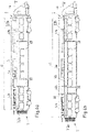
- FIG 4a a carriage 1 of a rail vehicle with a modular component framework 2 is shown in a further embodiment.
- the modular component framework includes a first functional module 3a and a second functional module 3b.
- the first function module 3a has a module length L3a and the second function module 3b has a module length L3b, these lengths L3a, L3b being the same are.
- the function modules 3a, 3b are standard modules that are not specific to the vehicle.
- the modular component framework 2 also includes a vehicle-unspecific module 4, which has a module length L4.
- the functional modules 3a, 3b are end-of-carriage modules.
- the second functional module 3b is arranged in front of the further module 4, which is a vehicle-specific module, along the longitudinal axis x of the vehicle.
- This further module 4 in turn is arranged in front of the first function module 3a.
- the sum of the module lengths L3a, L3b, L4 corresponds to an installation length L1 for the modular component framework 2.
- FIG 4b a further embodiment of a modular component framework 2 for arrangement in a carriage 1 of a rail vehicle is shown.
- the modular component framework 2 includes, in addition to the two standard function modules 3a, 3b, two further, car-specific modules 4a, 4b with the module lengths L4a, L4b.
- the length of the function modules 3a, 3b corresponds to the module lengths L3a, L3b in Figure 4a illustrated embodiment.
- the module length L4b of the second car-specific module 4b is longer than that of in Figure 4a shown car-specific module.
- the modular component framework 2 can be compared to that in Figure 4a illustrated embodiment of the carriage 1 greater length of the carriage 1 and thus the greater installation length L1 are adjusted.
- a desired, car-specific function can be provided by a car-specific design of the additional modules 4a, 4b. It is also possible to provide a car section-specific function by designing a car-specific module 4a, 4b.
- the first car-specific module 4a is a pure extension module, which does not include a functional element but only connecting elements for the electrical and/or fluidic connection between the second functional module 3b and the second additional module 4b.
- the extension module does not include any connecting elements and is used to receive connecting elements of other modules after they have been attached to one another.
- Figure 5b shows a schematic perspective view of a modular component framework 2 of FIG Figure 3a illustrated embodiment. Shown is a car-unspecific module 4, a first functional module 3a and a further functional module 3b, the functional modules 3a, 3b being standard modules. Interfaces 15 between the modules 3a, 3b, 4 can also be seen. It can be seen that the function modules 3a, 3b each comprise a carrier 34, with the carrier 34 forming or having a line channel 31. It can also be seen that the second functional module 3b includes light sources 5, which can form functional elements of this module 3b, for example. The second functional module 3b (like the first and the third functional module 3a, 3c) can also include functional elements such as a control device 28 for controlling display devices 6 and a smoke alarm device 23. Alternatively or cumulatively, this control device 28 can be used to control audio communication with passengers in the car, for example via loudspeakers.
- a control device 28 for controlling display devices 6 and a smoke alarm device 23.
- this control device 28 can be used to control audio
- a carriage connection 16 which is formed by the second function module 3b.
- a car connection 16 which is formed by the additional, car-unspecific module 4.
- the further module 4 has no cable duct.
- Figure 5b shows a further embodiment of the modular component framework 2, which corresponds to that in Figure 3b shown component framework 2 corresponds. It can be seen here that the function modules 3a, 3b are the same as in Figure 5a illustrated function modules 3a, 3b are formed. These are standard modules from a set of predetermined standard modules.
- the illustrated embodiment of the component framework 2 is the module length L4 (see Figure 3b ) of the further module 4 longer, whereby the modular component framework can be adapted to the greater installation length L1 of the carriage 1.
- FIG. 6 shows a perspective view of two function modules 3a, 3b, the carrier 34 of the function modules 3a, 3b being shown in each case. Also visible is an interface 15, which is designed on the one hand for the mechanical connection of the function modules 3a, 3b, in particular the mechanical connection of the carrier 34. The interface 15 is also for the electrical connection between the function modules 3a, 3b, in particular between electrical or electronic components 32 of these functional modules 3a, 3b, which can form the functional elements of the functional modules 3a, 3b. In this case, the electrical connections of the components to the interface are represented symbolically by arrows.
- the interface 15 of a function module 3a, 3b can also serve as an interface for connecting an electrical line, which is installed, for example, in a line or cable duct 31 (see 2 ) of the respective module 3a, 3b can be arranged.
- a first framework module 3a is provided as a vehicle-unspecific standard module, which is selected, for example, from a set of predetermined standard modules 3a, 3b, . . . , 3n.
- a set of predetermined standard modules 3a, 3b, . . . , 3n can also be selected and made available in the first step S1.
- a second step S2 another, car-specific framework module 4 is provided (see e.g Figure 5a ).
- This further framework module 4 can be manufactured specifically for the car in the second step.
- a third step S3 the modular component framework 2 is arranged in a car body of the car 1 of the rail vehicle.
- the modules 3, 4 of the component framework 2 can be arranged in an unconnected state or in an already electrically, fluidically and/or mechanically connected state by means of a suitable transport device in the car interior.
- the transport device can bring the modular component framework into the car body via openings on the front side of the car body, for example an opening in a rear wall on the front side.
- the modules can then be connected to one another and/or connected to the car body of the car 1 .
Landscapes
- Engineering & Computer Science (AREA)
- Life Sciences & Earth Sciences (AREA)
- Wood Science & Technology (AREA)
- Mechanical Engineering (AREA)
- Automobile Manufacture Line, Endless Track Vehicle, Trailer (AREA)
- Automatic Assembly (AREA)
Abstract
Description
- Die Erfindung betrifft ein modulares Komponentengerüst zur Anordnung im Wagen eines Schienenfahrzeugs, ein Wagen eines Schienenfahrzeugs sowie ein Verfahren zur Herstellung eines solchen Wagens.
- Aus der
EP 2 217 483 B1 ist eine Montageeinheit zur Installation in einem Wagenkastenaufbau eines Schienenfahrzeugs bekannt. Die Druckschrift offenbart eine solche Montageeinheit mit einem Träger, der im Inneren des Wagenkastenaufbaus in einem Bereich unterhalb des Wagenkastendachs befestigbar ist. Weiter umfasst die Montageeinheit mindestens eine Versorgungsleitung, die am Träger vormontiert ist, und mehrere, mit der Versorgungsleitung verbundenen Versorgungseinrichtungen bzw. Funktionsbaugruppen, die am Träger vormontiert sind. Weiter offenbart die Druckschrift ein Verfahren zum Herstellen eines Schienenfahrzeugs unter Verwendung einer derart ausgebildeten Montageeinheit, bei dem ein Wagenkastenaufbau des Schienenfahrzeugs bereitgestellt wird und der Träger im Inneren des Wagenkastenaufbaus in einem Bereich unterhalb des Wagenkastendachs befestigt wird. - Weiter bekannt ist, dass verschiedene Schienenfahrzeuge jeweils fahrzeugspezifische Wagen umfassen können, die beispielsweise voneinander verschiedene Längen aufweisen können. Auch bekannt ist, dass verschiedene Funktionalitäten in verschiedenen Schienenfahrzeugen bzw. deren Wagen bereitgestellt werden sollen.
- Es stellt sich daher das technische Problem, ein modulares Komponentengerüst zur Anordnung in einem Wagen eines Schienenfahrzeugs, einen Wagen eines Schienenfahrzeugs sowie ein Verfahren zur Herstellung eines solchen Wagens zu schaffen, die eine einfache, kostengünstige Herstellung eines solchen Wagens ermöglichen, wobei gleichzeitig wagenspezifische Anforderungen in einfacher Weise erfüllt werden können. Insbesondere stellt sich das technische Problem, die Herstellung einer Vielzahl von voneinander verschiedenen Wagen, insbesondere von Wagen mit verschiedenen Längen und/oder verschiedener funktioneller Ausstattung, zu vereinfachen.
- Die Lösung des technischen Problems ergibt sich durch die Gegenstände mit den Merkmalen der unabhängigen Ansprüche. Weitere vorteilhafte Ausgestaltungen der Erfindung ergeben sich aus den Unteransprüchen.
- Vorgeschlagen wird ein modulares Komponentengerüst zur Anordnung in einem Wagen eines Schienenfahrzeugs. Das Komponentengerüst dient zur Anordnung, insbesondere zur Befestigung, von Komponenten des Wagens des Schienenfahrzeugs und kann somit auch als Komponententräger bezeichnet werden. Komponenten können Elemente, insbesondere Funktionselemente, des Wagens oder des Schienenfahrzeugs sein. Komponenten umfassen jedoch auch Verbindungselemente, z.B. zur Herstellung einer elektrischen oder fluidtechnischen Verbindung. Z.B. kann ein Verbindungselement eine elektrische Leitung sein.
- Das modulare Komponentengerüst umfasst ein Gerüstmodul.
- Erfindungsgemäß umfasst das Komponentengerüst mindestens ein weiteres Gerüstmodul. Somit umfasst das modulare Komponentengerüst also wenigstens zwei Module, vorzugsweise jedoch mehr als zwei, insbesondere drei, vier oder fünf Module. Ein Modul der Modulgesamtheit kann hierbei mit mindestens einem weiteren Modul mechanisch und/oder elektrisch und/oder fluidtechnisch verbunden sein.
- Mindestens ein Gerüstmodul der Modulgesamtheit, mehrere, aber nicht alle Gerüstmodule der Modulgesamtheit oder aber alle Gerüstmodule der Modulgesamtheit können Befestigungsmittel oder -schnittstellen zur Befestigung an einem Wagenkasten des Wagens aufweisen oder ausbilden. Derartige Gerüstmodule können mit dem Wagenkasten mechanisch verbunden werden, beispielsweise über Montagebügel oder sonstige mechanische Verbindungsweisen, z.B. über eine Verschraubung.
- Die Gerüstmodule können insbesondere in einem Deckenbereich des Wagenkastens angeordnet und dort befestigt werden. Alternativ oder kumulativ ist es jedoch, die mindestens ein Gerüstmodul in einem Bodenbereich, insbesondere einem Unterflurbereich, anzuordnen und zu befestigen. Weiter alternativ oder kumulativ ist es möglich, mindestens ein Gerüstmodul in einem Seitenwandbereich des Wagenkastens anzuordnen und zu befestigen.
- Ein Gerüstmodul kann zur Aufnahme mindestens einer elektrischen Leitung dienen. Insbesondere kann ein Modul einen Leitungskanal, der auch als Kabelkanal bezeichnet werden kann, umfassen oder ausbilden. Eine elektrische Leitung kann eine Leitung zur Energieversorgung einer elektrischen oder elektronischen Komponente des Wagens dienen. Alternativ kann eine elektrische Leitung einer Signalübertragung, beispielsweise von Steuersignalen oder anderen Signalen, zu einer solchen Komponente oder von einer solchen Komponente dienen.
- Insbesondere kann ein Modul Mittel zur Führung der mindestens einen elektrischen Leitung aufweisen oder ausbilden. Auch kann ein Modul Mittel zur Befestigung der mindestens einen elektrischen Leitung aufweisen oder ausbilden. Derartige Führungs- und/oder Befestigungsmittel können beispielsweise als Kabelklemme, Kabelhalterung oder sonstige Kabelführungselemente ausgebildet sein. Es ist möglich, dass derartige Führungs- und/oder Befestigungsmittel lösbar an dem Modul befestigt sind.
- Insbesondere können die Führungsmittel (und gegebenenfalls die Befestigungsmittel) derart konfiguriert sein, dass eine Leitungsführung derart ermöglicht wird, dass vorbestimmte EMV-Kriterien erfüllt sind.
- Weiter kann ein Gerüstmodul eine elektrische Leitung oder eine Vielzahl von elektrischen Leitungen, beispielsweise in Form eines Kabelstrangs oder Leitungsbunds, umfassen. Hierbei kann die mindestens eine elektrische Leitung, insbesondere der Kabelstrang oder Leitungsbund, eines Gerüstmoduls eine modulspezifische Länge aufweisen.
- Diese können an dem Gerüstmodul vormontiert sein, insbesondere mit Mitteln zur Befestigung an dem Gerüstmodul befestigt sein. Hierbei kann die Leitung oder können die Leitungen mit durch Mittel zur Führung geführt sein, beispielsweise damit ein gewünschter Verlauf bereitgestellt wird. Weiter insbesondere kann durch ein solches Gerüstmodul ein Verlauf der elektrischen Leitung(en) gemäß einem vorbestimmten Stromlaufplan bereitgestellt sein. Auch kann durch ein solches Gerüstmodul eine gewünschte Verbindung (Verdrahtung) zwischen verschiedenen Elementen, insbesondere Funktionselementen, des Gerüstmoduls bereitgestellt sein.
- Alternativ, vorzugsweise aber kumulativ, kann ein Modul mindestens einen Klimakanal umfassen oder ausbilden. Ein solcher Klimakanal kann zur Führung eines Fluidstroms, insbesondere eines Luftstroms, dienen, wobei dieser Fluidstrom zur Einstellung einer gewünschten Temperatur im Wagen des Schienenfahrzeugs, insbesondere in einem Innenraum, genutzt wird.
- Mit anderen Worten kann ein Modul Bauraum für elektrische Verbindungselemente und/oder fluidtechnische Verbindungselemente umfassen oder ausbilden. Im Falle von fluidtechnischen Verbindungselementen kann der Bauraum das fluidtechnische Verbindungselemente bereitstellen. Weiterhin kann das Modul Elemente umfassen, die einen Fluideintritt oder Fluidaustritt, insbesondere eine Volumenstrommenge, steuern können. Weiter kann das Modul Elemente zur Fluidführung umfassen.
- Weiter ist es möglich, dass ein Modul einen Leerkanal aufweist oder ausbildet, der zur nachträglichen Anordnung von z.B. weiteren elektrischen Leitungen dienen kann.
- Es ist möglich, dass ein Modul zwei, insbesondere mindestens oder genau zwei, Leitungskanäle für elektrische Leitungen und mindestens einen, insbesondere genau einen, Klimakanal umfasst, wobei der Klimakanal zwischen den beiden Aufnahmekanälen angeordnet ist. Insbesondere kann der Klimakanal entlang einer Wagenquerrichtung zwischen den beiden Aufnahmekanälen angeordnet sein. In diesem Fall ist es möglich, dass zumindest ein Abschnitt des Klimakanals entlang einer Wagenvertikalrichtung auf gleicher Höhe wie die beiden Aufnahmekanäle angeordnet ist.
- Alternativ kann ein Modul mindestens zwei, insbesondere genau zwei, Klimakanäle und mindestens einen, insbesondere genau einen, Leitungskanal für elektrische Leitungen umfassen, wobei der Aufnahmekanal zwischen den beiden Klimakanälen angeordnet ist. Auch in diesem Fall kann der Aufnahmekanal entlang der Wagenquerrichtung zwischen den beiden Klimakanälen angeordnet sein, wobei gegebenenfalls zumindest ein Abschnitt des Aufnahmekanals entlang der Wagenvertikalrichtung in gleicher Höhe wie die beiden Klimakanäle angeordnet ist.
- Eine Wagenlängsrichtung kann hierbei parallel zu einer Wagenlängsachse orientiert sein, die auch als Rollachse des Wagens bezeichnet werden kann. Eine Wagenvertikalrichtung kann hierbei parallel zu einer Vertikalachse des Wagens orientiert sein, die auch als Wagengierachse oder Wagenhochachse bezeichnet werden kann. Diese kann entgegengesetzt zur Richtung einer Gravitationskraft, insbesondere von einer Wagenunterseite zu einer Wagenoberseite, orientiert sein. Weiter kann die Wagenquerrichtung parallel zu einer Wagenquerachse, die z.B. eine Wagennickachse sein kann, orientiert sein. Diese kann wiederum senkrecht zur erläuterten Wagenlängsachse und Wagenvertikalachse orientiert sein.
- Weiter ist ein erstes Gerüstmodul ein Funktionsmodul. Das Funktionsmodul im Sinne dieser Offenbarung bezeichnet hierbei ein Modul mit einer Komponente oder einem (Funktions-)Element, die/das eine gewünschte, also vorbestimmte, Funktionalität bereitstellt. Eine Funktionalität kann bereitgestellt werden, wenn ein Modul bzw. mindestens eine Komponente des Moduls mindestens eine vorbestimmte Funktion ausführen kann. Somit kann ein solches Funktionsmodul auch einen Bauraum für das mindestens eine Funktionselement bereitstellen.
- Mit anderen Worten ist es möglich, dass ein Modul den Bauraum zur Anordnung der erläuterten Elemente und Leitungen bereitstellt. Ist das Modul ein Funktionsmodul, so ist es zusätzlich möglich, dass das Modul ein Funktionselement umfasst.
- Umfasst ein Modul sowohl ein Funktionselement als auch eine elektrische Leitung, so kann das Funktionselement mit der elektrischen Leitung verbunden sein. Ist die elektrische Leitung in einem Leitungskanal des Funktionsmoduls angeordnet, so kann ein Verbindungsabschnitt der elektrischen Leitung von dem Funktionselement zu dem/in den Leitungskanal geführt werden. Hierzu kann der Kabelkanal entsprechende Öffnungen aufweisen. Es ist möglich, dass das Funktionsmodul den Verbindungsabschnitt bereitstellt oder dieser Verbindungsabschnitt kann separat vom Funktionsmodul ausgebildet und angeordnet sein.
- Weiter ist das erste Gerüstmodul ein wagenunspezifisches Standardmodul. Dies kann bedeuten, dass die Eigenschaften, z.B. eine Dimension und/oder die von dem Modul bereitgestellte Funktionalität, des Gerüstmoduls wagenunspezifisch festgelegt sind.
- Ein Standardmodul kann hierbei ein Modul einer Menge von mehreren voneinander verschiedenen Standardmodulen sein. Solche Standardmodule können voneinander verschiedene Eigenschaften aufweisen. Insbesondere können diese Standardmodule voneinander verschiedene vorbestimmte Dimensionen, insbesondere Längen, aufweisen und/oder voneinander verschiedene vorbestimmte Funktionalitäten bereitstellen.
- Umfassen die Module einer Menge von mehreren voneinander verschiedenen Standardmodulen mindestens eine elektrische Leitung, beispielsweise in Form eines Kabelstrangs oder Leitungsbunds, so können elektrischen Leitungen verschiedener Module voneinander verschiedene modulspezifische Längen aufweisen. Es ist insbesondere möglich, dass verschiedene Standardmodule mit gleicher Länge jeweils mindestens eine elektrische Leitung, beispielsweise in Form eines Kabelstrangs oder Leitungsbunds, umfassen, wobei die elektrischen Leitungen verschiedener Module voneinander verschiedene modulspezifische Längen aufweisen. Die mindestens eine elektrische Leitung verschiedener Module können jedoch die gleichen Schnittstellen zum Anschluss aufweisen oder ausbilden, beispielsweise als Steckverbinder ausgebildete Anschlüsse.
- Ein wagenunspezifisches Standardmodul kann weiter ein Modul bezeichnen, welches in verschiedenen Wagen eines Schienenfahrzeugs oder in Wagen verschiedener Schienenfahrzeuge verbaubar ist, insbesondere ohne eine Anpassung/Veränderung der Dimension und/oder der bereitgestellten Funktionalität(en).
- Ein wagenunspezifisches Standardmodul kann insbesondere ein wiederverwendbares Modul sein. Das kann bedeuten, dass ein in einem Wagen verwendetes Modul aus dem Wagen ausgebaut und zur weiteren Verwendung in einen davon verschiedenen Wagen eingebaut wird. Es ist hierbei insbesondere möglich, dass das Gerüstmodul ohne Veränderung der Anzahl und/oder Lage der Elemente des Gerüstmoduls wiederverwendet wird. Somit können also die Elemente des Gerüstmoduls und/oder ein durch das Gerüstmodul bereitgestellter Stromlaufplan und/oder eine durch das Gerüstmodul bereitgestellte elektrische Verbindung verschiedener Elemente und/oder Teile der mechanischen Konstruktion bzw. die mechanische Konstruktion des Gerüstmoduls wiederverwendet werden. Mit anderen Worten kann z.B. auch ein Leitungsbund des Gerüstmoduls wiederverwendet werden.
- Mit anderen Worten sind Eigenschaften des wagenunspezifischen Standardmoduls schienenfahrzeug- bzw. wagenunspezifisch festgelegt, d.h. nicht an einen spezifischen Wagen bzw. ein spezifisches Schienenfahrzeug angepasst. Somit kann durch ein solches Modul auch ein wagenunspezifischer Stromlaufplan, eine wagenunspezifische elektrische Verbindung verschiedener Elemente des Moduls bereitgestellt werden.
- Weiter ist das mindestens eine weitere Gerüstmodul ein wagenspezifisches Gerüstmodul. Dies kann bedeuten, dass mindestens eine Eigenschaft des Gerüstmoduls wagenspezifisch festgelegt ist. Insbesondere kann eine Länge des weiteren Gerüstmoduls wagenspezifisch festgelegt sein. Eine Länge bezeichnet hierbei eine Dimension entlang der vorhergehend erläuterten Längsachse.
- Das wagenspezifische, weitere Gerüstmodul kann insbesondere kein Funktionsmodul sein. In diesem Fall kann das Modul kein nachfolgend noch näher erläutertes Funktionselement umfassen. Allerdings ist es auch möglich, dass das weitere Modul ein Funktionsmodul ist.
- Es ist insbesondere möglich, dass das wagenspezifische, weitere Gerüstmodul ein Dummy-Modul oder Verlängerungsmodul ist. Ein solches Modul kann insbesondere keine elektrische Leitung, insbesondere in Form eines Kabelstrangs oder Leitungsbunds, umfassen. Das Verlängerungsmodul kann aber Mittel zur Führung mindestens einer elektrischen Leitung aufweisen oder ausbilden. Auch kann ein Modul Mittel zur Befestigung der mindestens einen elektrischen Leitung aufweisen oder ausbilden. Es ist in diesem Fall aber möglich, dass ein Verlängerungsmodul Funktionselement umfasst. Allerdings ist es auch möglich, dass das Verlängerungsmodul kein Funktionselement umfasst.
- Durch das vorgeschlagene modulare Komponentengerüst ergibt sich in vorteilhafter Weise eine einfache Herstellung eines Wagens eines Schienenfahrzeugs (und somit auch eines Schienenfahrzeugs mit mehreren solcher Wagen), insbesondere eine einfache Herstellung von Wagen verschiedener Schienenfahrzeuge oder von verschiedenen Wagen eines Schienenfahrzeugs. Insbesondere kann nämlich zur Herstellung des Komponentengerüsts mindestens ein wagenunspezifisches Standardmodul verwendet werden. Weiter kann die wagenspezifische Anpassung des modularen Komponentengerüsts dann durch die Herstellung und weitere Verwendung eines wagenspezifischen Gerüstmoduls erfolgen.
- Insbesondere kann in einfacher Weise die Länge des Komponentengerüsts an die Länge, insbesondere die Einbaulänge, des Wagens angepasst werden.
- Hierbei ist es möglich, dass mindestens ein wagenunspezifisches Standardmodul und mindestens eine Verlängerungsmodul verwendet wird, wobei das Standardmodul mindestens eine elektrische Leitung, insbesondere in Form eines Kabelstrangs oder Leitungsbunds, umfasst, wobei die Länge der mindestens einen elektrischen Leitung des Standardmoduls derart gewählt ist, dass ein Abschnitt der elektrischen Leitung des Standardmoduls nach der Befestigung der Module aneinander in dem Verlängerungsmodul angeordnet wird. Beispielsweise kann die mindestens eine elektrische Leitung in das Verlängerungsmodul ausgerollt werden. Dort kann die mindestens eine elektrische Leitung dann in gewünschter Weise geführt angeordnet und gegebenenfalls auch befestigt werden. In diesem Fall kann also die Länge der mindestens einen elektrischen Leitung eines Standardmoduls länger sein als eine vom Standardmodul für die elektrische Leitung bereitgestellte Einbaulänge. Z.B. kann die Länge der mindestens eine elektrischen Leitung der vom Wagen bereitgestellten Einbaulänge für das Komponentengerüst entsprechen.
- Weist ein erster Wagen eine erste Länge und ein weiterer Wagen eine weitere Länge, die kürzer als die erste Länge ist, auf, so ist es also möglich, dass zur Herstellung eines Komponentengerüsts für beide Wagen jeweils die Standardmodule mit gleicher Länge verwendet werden, wobei die elektrischen Leitungen dieser Standardmodule jedoch verschiedene Längen aufweisen.
- So kann zur Herstellung eines Komponentengerüsts für den ersten Wagen ein Standardmodul mit einer elektrischen Leitung verwendet werden, die eine erste Länge aufweist. Weiter kann zur Herstellung eines Komponentengerüsts für den zweiten Wagen ein Standardmodul mit einer elektrischen Leitung verwendet werden, die eine zweite Länge aufweist, die kürzer als die erste Länge ist. Mit anderen Worten können für verschiedene Wagen die Standardmodule gleicher Länge verwendet werden, die aber kurze oder lange Kabelbäume umfassen können.
- Weiter kann zur Herstellung des Komponentengerüsts für den ersten Wagen oder zur Herstellung der Komponentengerüste für beide Wagen jeweils ein Verlängerungsmodul verwendet werden, in dem dann die elektrische Leitung des Standardmoduls angeordnet wird. Längere elektrische Leitungen eines Standardmoduls können hierbei eine Flexibilität für die Verwendung in längeren Wagen bieten.
- Somit lassen sich in vorteilhafter Weise ein Fertigungsaufwand zur Herstellung des Komponentengerüsts in einem Wagen eines Schienenfahrzeugs sowie auch die Herstellungskosten für den Wagen minimieren.
- In einer weiteren Ausführungsform umfasst ein Funktionsmodul mindestens ein Funktionselement und mindestens ein Steuerungselement zur Steuerung des Funktionselements.
- Ein Funktionselement kann insbesondere eine Lichtquelle sein, beispielsweise ein Lichtband zur Beleuchtung eines Innenraums des Wagens. Auch kann ein Funktionselement ein Lautsprecher, eine Anzeigeeinrichtung, beispielsweise ein Bildschirm, eine Heizeinrichtung, eine Kühleinrichtung oder eine Belüftungseinrichtung, z.B. in Form eines Lüfters, sein. Auch kann ein Funktionselement eine Bilderfassungseinrichtung sein, beispielsweise zur Erfassung eines (Teils des) Wageninnenraums oder eines (Teils des) Wagenaußenraums. Die Aufzählung von Funktionselementen ist hierbei beispielhaft und nicht abschließend.
- Umfasst das Funktionsmodul ein Funktionselement, so kann dieses im Modul befestigt sein, beispielsweise über eine geeignete Haltevorrichtung des Moduls.
- Ein Steuerungselement zur Steuerung des Funktionselements kann insbesondere eine Steuereinrichtung z.B. in Form eines Mikrocontrollers oder einer integrierten Schaltung sein. Auch das Steuerungselement kann hierbei an dem Modul befestigt sein.
- Es ist weiter möglich, dass ein Funktionsmodul ein Versorgungselement zur Energieversorgung des Funktionselements und/oder des Steuerungselements umfasst. Ein solches Energieversorgungselement kann beispielsweise eine Energiespeichereinrichtung, beispielsweise eine Batterie oder ein Akkumulator, sein. Auch kann ein Versorgungselement ein Strom- oder Spannungswandler sein, beispielsweise ein DC/DC-Wandler, ein AC/DC-Wandler oder ein DC/AC-Wandler. Auch kann ein Versorgungselement ein Transformator sein. Weiter kann ein Versorgungselement ein Verteilerelement sein. Auch das Versorgungselement kann hierbei an dem Modul befestigt sein.
- Es ist ebenfalls möglich, dass ein Funktionsmodul mindestens ein Sicherungselement umfasst, beispielsweise ein Stromsicherungselement, also eine elektrische Sicherung. Auch das Sicherungselement kann hierbei an dem Modul befestigt sein.
- Die verschiedenen Elemente eines Funktionsmoduls können hierbei in einer vorbestimmten, gewünschten Weise elektrisch miteinander verbunden sein. Ebenfalls ist es möglich, dass mindestens eines der Elemente über elektrische Verbindungsmittel des Funktionsmoduls mit nachfolgend noch näher erläuterten Schnittstellen des Moduls und/oder Anschlüssen des Moduls verbunden ist.
- Durch die Anordnung des Funktionselements und des mindestens einen Steuerelements zur Steuerung des Funktionselements in dem Funktionsmodul ergibt sich in vorteilhafter Weise eine Dezentralisierung der zur Bereitstellung einer gewünschten Funktionalität erforderlichen Elemente und dass die gewünschte Funktionalität möglichst unabhängig von spezifischen Anforderungen externer Elemente bereitgestellt werden kann. Dies wiederum vereinfacht die Integration des Komponentengerüsts in das Schienenfahrzeug und somit auch die Herstellung. Insbesondere kann eine Länge der zur Verbindung der Elemente dienenden elektrischen Leitungen reduziert werden, da z.B. ein Funktionselement eines Moduls nicht mit einem Steuerungselement außerhalb des Moduls verbunden werden muss.
- In einer weiteren Ausführungsform ist das erste Gerüstmodul ein vormontiertes Gerüstmodul. Alternativ oder kumulativ ist das weitere Gerüstmodul ein vormontiertes Gerüstmodul. Dies kann insbesondere bedeuten, dass Komponenten eines Moduls, insbesondere die vorhergehend erläuterten Elemente, aber auch die vorhergehend erläuterten elektrischen Leitungen bereits vor der Montage, insbesondere vor der Einbringung, des Moduls am/in den Wagenkasten, an dem Modul befestigt sind. Dies ermöglicht in vorteilhafter Weise eine einfache Montage der Komponenten, insbesondere da vor der Einbringung in den Wagenkasten eine einfacherere Zugänglichkeit des Moduls gegeben ist als in einem Zustand, in dem das Modul bereits im Wagenkasten angeordnet ist. Auch ermöglicht die Vormontage in vorteilhafter Weise, dass bereits vor dem Einbau in den Wagenkasten eine Funktionsprüfung durchgeführt werden kann, was wesentlich weniger aufwendig ist als bei einer bereits erfolgen Montage. Ferner kann bei einer Fehlfunktion außerhalb des Wagenkastens eine einfache Reparatur durchgeführt werden.
- Die elektrische Anbindung der Komponenten eines Moduls kann dann über entsprechende Schnittstellen oder Anschlüsse des Moduls erfolgen. Diese Anschlüsse oder Schnittstellen können insbesondere zur Herstellung von Steckverbindungen zwischen zwei Modulen oder zu einem Modul dienen.
- In einer weiteren Ausführungsform umfasst ein Gerüstmodul eine standardisierte Haltevorrichtung für mindestens ein Funktionselement oder bildet diese Haltevorrichtung aus. Eine solche Haltevorrichtung kann insbesondere ein sogenanntes 19-Zoll-Gerüst sein. Hierdurch wird in vorteilhafter Weise ein Einbau für standardisierte Funktionselemente vereinfacht. Dies wiederum ermöglicht eine vereinfachte Herstellung des Wagens.
- In einer weiteren Ausführungsform weist ein Gerüstmodul eine, insbesondere genau eine, Schnittstelle, zur elektrischen Anbindung des Gerüstmoduls auf. Dies kann bedeuten, dass die Komponenten eines Gerüstmoduls, insbesondere nur, über diese Schnittstelle mit modulexternen Komponenten elektrisch verbindbar sind.
- Diese Schnittstelle kann eine Schnittstelle zur Verbindung mit mindestens einem weiteren Gerüstmodul sein. Wie vorhergehend erläutert, kann eine solche Schnittstelle zur Herstellung einer Steckverbindung zwischen den beiden Modulen ausgebildet sein. Eine Schnittstelle zur elektrischen Verbindung kann beispielsweise eine elektrische Verbindung von elektrischen Leitungen in einem Kabelkanal eines Gerüstmoduls mit elektrischen Leitungen im Kabelkanal eines weiteren Gerüstmoduls ermöglichen. Die Schnittstellen können somit einen Stecker aufweisen oder ausbilden.
- Die Schnittstelle kann aber auch eine Schnittstelle zum Anschluss an elektrische Leitungen sein, die in einem modulexternen Leitungskanal des Wagens angeordnet sind. Ein solcher modulexterner Leitungskanal kann z.B. an dem Wagenkasten befestigt sein oder von diesem ausgebildet werden.
- Alternativ oder kumulativ weist ein Gerüstmodul eine Schnittstelle zur fluidtechnischen Anbindung des Gerüstmoduls auf. Diese Schnittstelle kann eine Schnittstelle zur fluidtechnischen Verbindung mit mindestens einem weiteren Gerüstmodul oder mit einer modulexternen Einrichtung sein. Beispielsweise kann eine solche Schnittstelle eine Verbindung zwischen einem Klimakanal des Gerüstmoduls mit einem Klimakanal eines weiteren Gerüstmoduls ermöglichen.
- Hierdurch ergibt sich in vorteilhafter Weise eine einfache elektrische und/oder fluidtechnische Verbindung verschiedener Module, wodurch wiederum die Herstellung eines Wagens vereinfacht wird.
- Es ist selbstverständlich auch möglich, dass ein Gerüstmodul Schnittstellen zur mechanischen Anbindung des Gerüstmoduls aufweist. Eine solche Schnittstelle kann zur Verbindung verschiedener Gerüstmodule oder zur Verbindung mit dem Wagenkasten dienen. Solche Schnittstellen können beispielsweise eine Schraubverbindung, eine Rastverbindung, eine Klemmverbindung oder eine sonstige Verbindung ermöglichen. Auch ist es möglich, dass eine Schnittstelle zur elektrischen und/oder zur fluidtechnischen Anbindung gleichzeitig als Schnittstelle zur mechanischen Verbindung ausgebildet ist.
- In einer weiteren Ausführungsform weist ein Wagenendmodul zusätzlich elektrische und/oder fluidtechnische Wagenanschlüsse auf. Dies dienen zur elektrischen und/oder fluidtechnischen Anbindung des Wagenendmoduls, insbesondere zur elektrischen und/oder fluidtechnischen Verbindung mit wagenexternen Komponenten, z.B. in einem weiteren, insbesondere benachbarten, Wagen.
- Ein solcher Wagenanschluss kann zur Herstellung einer Steckverbindung ausgebildet sein. Somit kann ein solcher Wagenanschluss einen Stecker umfassen oder ausbilden. Ein solcher Wagenanschluss dient hierbei nicht zur Verbindung zwischen zwei Modulen eines Wagens. Vielmehr kann ein Wagenanschluss zur elektrischen und/oder fluidtechnischen Verbindung mit einem Modul eines weiteren Wagens oder zum Anschluss von oder Verbinden mit Modulen dienen, die außerhalb des Wagens angeordnet sind, z.B. auf einem Wagendach oder in einem Wagenunterflurbereich, dienen. Allerdings kann ein solcher Anschluss auch zur Verbindung mit wagenexternen elektrischen Leitungen und/oder Klimakomponenten dienen. Hierdurch ergibt sich in vorteilhafter Weise ebenfalls eine vereinfachte Herstellung eines Wagens.
- In einer weiteren Ausführungsform ist ein Standardmodul ein Beleuchtungsmodul. Ein Beleuchtungsmodul kann hierbei mindestens eine Lichtquelle als Funktionselement umfassen. Weiter kann ein Beleuchtungsmodul - wie vorhergehend erläutert - ein Steuerungselement zur Steuerung der Lichtquelle, also z.B. zur Einstellung einer Beleuchtungsintensität und/oder einer Wellenlänge der Beleuchtung, umfassen. Eine Lichtquelle kann beispielsweise als Lichtband ausgebildet sein.
- Auch kann ein Standardmodul ein Spannungswandlermodul sein. Ein Spannungswandlermodul kann beispielsweise als Funktionselement einen Spannungswandler, beispielsweise einen Hochsetzsteller, einen Tiefsetzsteller, einen aktiven oder passiven Gleichrichter oder einen Wechselrichter umfassen.
- Auch kann ein Standardmodul ein Spannungsverteilermodul sein. Ein Spannungsverteilermodul kann beispielsweise als Funktionselement einen Transformator umfassen, der eine Primärwindung und mindestens zwei Sekundärwindungen aufweist. Auch kann ein Spannungsverteilermodul als Funktionselement eine Verteileinrichtung umfassen, die einen Eingangsanschluss und mehrere Ausgangsanschlüsse aufweist, an die elektrische Leitungen angeschlossen werden können, wobei z.B. die Eingangsspannung am Eingangsanschluss an jedem der Ausgangsanschlüsse abgreifbar ist. Auch ist es möglich, dass die an ausgewählten Ausgangsanschlüssen abgreifbare Spannung durch eine Wandlung der Eingangsspannung hochgesetzt oder tiefgesetzt wird. In diesem Fall kann das Spannungsverteilermodul auch ein Spannungswandlermodul sein. Ferner kann ein Spannungsverteilermodul Sicherungselemente, Schaltelemente oder andere Funktionselemente einer Verteilereinrichtung umfassen.
- An diese Ausgangsanschlüsse können z.B. weitere Funktionselemente bzw. Verbraucher angeschlossen werden.
- Auch kann ein Standardmodul ein Lautsprechermodul sein. Ein Lautsprechermodul kann als Funktionselement mindestens einen Lautsprecher umfassen. Im Sinne dieser Offenbarung kann ein Lautsprecher eine Einrichtung zur Erzeugung akustischer Signale bezeichnen.
- Auch kann ein Standardmodul ein Klimatisierungsmodul sein. Ein solches Modul kann als Funktionselement eine Heizeinrichtung, eine Kühleinrichtung oder sowohl eine Heiz- als auch eine Kühleinrichtung, die beispielsweise kombiniert oder separat voneinander ausgebildet sein können, umfassen. Weiter kann ein Klimatisierungsmodul als Funktionselement eine Einrichtung zur Erzeugung eines Fluidstroms, beispielsweise eine Pumpe oder einen Lüfter, umfassen. Weiter kann ein Klimatisierungsmodul eine Filtereinrichtung, insbesondere eine aktive Filtereinrichtung, zur Filterung des erläuterten Fluidstroms umfassen.
- Auch kann ein Standardmodul ein Infotainmentmodul sein. Ein Infotainmentmodul kann als Funktionselement beispielsweise eine Anzeigeeinrichtung umfassen. Es ist möglich, dass ein Infotainmentmodul, zusätzlich zu einer Anzeigeeinrichtung, auch eine Einrichtung zur Erzeugung von akustischen Signalen als Funktionselement umfasst.
- Auch kann ein Standardmodul ein Steuerungsmodul sein. Ein Steuerungsmodul kann als Funktionselement eine Steuerungselement, beispielsweise einen Mikrocontroller oder eine integrierte Schaltung, umfassen, durch die Steuersignale zur Steuerung eines Betriebs eines Funktionselements des gleichen Moduls, eines Funktionselements eines weiteren Moduls oder von modulexternen Funktionselementen erzeugt werden können. Beispielsweise kann ein solches Steuerungselement einen Betrieb von automatisch bewegbaren Türen des Wagens steuern. Insbesondere kann gesteuert werden, dass die Türen geschlossen oder geöffnet werden. Hierzu kann die Steuereinrichtung Steuersignale für entsprechende Aktoren erzeugen.
- Auch kann ein Standardmodul ein Netzwerkzugangsmodul sein. Ein solches Netzwerkzugangsmodul kann als Funktionselement eine Einrichtung zur Bereitstellung eines (lokalen) Netzwerks, insbesondere eines WLAN, umfassen. Weiter kann das Modul als Funktionselement eine Einrichtung zur datentechnischen Verbindung dieses Netzwerks mit einem weiteren Netzwerk, insbesondere einem wagenexternen Netzwerk, umfassen. Mit anderen Worten kann durch das genannte Modul ein sogenannter Hotspot bereitgestellt werden, der einen Netzwerkzugangspunkt für netzwerkfähige Endgeräte im Wagen bildet. Beispielsweise können diese dann eine datentechnische Verbindung zum Internet herstellen. Das genannte Modul kann als Funktionselement alle Einrichtungen umfassen, die zur Herstellung einer solchen Verbindung notwendig sind.
- Alle vorhergehend erläuterten Module umfassen mindestens ein Funktionselement, welches eine gewünschte Funktion, beispielsweise eine Beleuchtung, eine Spannungswandlung, eine Spannungsverteilung, eine Ausgabe akustischer Signale, eine Einstellung einer Temperatur, eine Informationsanzeige, eine Steuerung oder eine Bereitstellung eines Netzwerkzugangs ausführen bzw ausführen können. Die vorhergehend erläuterten Module können - wie vorhergehend erläutert - auch ein Steuerungselement zur Steuerung des Betriebs der entsprechenden Funktionselemente umfassen.
- Alternativ kann ein Standardmodul ein Mischmodul aus mindestens zwei dieser Module sein. Dies kann bedeuten, dass ein Mischmodul mindestens ein Funktionselement umfasst, durch welches mindestens zwei der durch die vorhergehend erläuterten Module bereitstellbare Funktionen ausführbar/bereitstellbar sind.
- Die angeführten Funktionen bilden Funktionen, die in der Regel in einem Wagen eines Schienenfahrzeugs bereitgestellt werden sollen. Solche Funktionen können Hauptversorgungsverteilungs- sowie Normstandardfunktionen sein. Durch die Integration der entsprechenden Funktionselemente in ein Standardmodul sind diese für eine Vielzahl von Wagen einsetzbar, was eine einfache Herstellung von einer Vielzahl von Wagen ermöglicht.
- In einer weiteren Ausführungsform ist ein weiteres Gerüstmodul ein Brandmeldemodul. Ein Brandmeldemodul kann als Funktionselement eine Erfassungseinrichtung zur Branderfassung, insbesondere zur Raucherfassung, umfassen. Eine solche kann beispielsweise als optischer, photoelektrischer Rauchmelder oder lonisationsrauchmelder oder als Wärmemelder, als Brandgasmelder, als CO-Melder, als Flammenmelder oder in einer alternativen Ausführungsform ausgeführter Brandmelder ausgeführt sein. Weiter kann ein Brandmeldemodul eine Einrichtung zur Ausgabe eines Warnsignals, beispielsweise eines optischen Warnsignals, eines akustischen Warnsignals oder eines Warnsignals in einer anderen Form, umfassen. Wie vorhergehend bezüglich des Standardmoduls erläutert, kann auch ein weiteres Gerüstmodul ein Steuerungselement zur Steuerung des Betriebs der Funktionselemente eines Brandmeldemoduls umfassen.
- Auch kann ein weiteres Gerüstmodul ein Verbindungsmodul sein. Ein Verbindungsmodul kann hierbei ein Modul bezeichnen, welches kein Funktionselement umfassen kann.
- Alternativ oder kumulativ kann ein Verbindungsmodul ein Modul sein, welches eine elektrische Verbindung zwischen zwei weiteren Modulen des Komponentengerüsts eines Wagens oder zwischen einem weiteren Modul des Komponentengerüstes und Wagenanschlüssen herstellt. Somit kann ein Verbindungsmodul die genannten Verbindungselemente wie z.B. elektrische Leitungen umfassen. Auch kann ein Verbindungsmodul Elemente zur fluidtechnischen Verbindung, beispielsweise mindestens einem Klimakanal, umfassen. Es ist möglich, dass ein Verbindungsmodul somit auch als Leitungsverlängerungsmodul ausgebildet sein kann.
- So kann ein Verbindungsmodul z.B. mindestens ein Verbindungselement, aber kein Funktionselement umfassen. Auch kann ein Verbindungsmodul z.B. mindestens ein Verbindungselement, aber kein Funktionselement und kein Steuerungselement umfassen.
- Da sowohl die Bereitstellung von geeigneten Verbindungen sowie eine Brandmeldefunktion in der Regel optionale Funktionen in einem Wagen eines Schienenfahrzeugs darstellen, ergibt sich in vorteilhafter Weise eine einfache Anpassung des modularen Komponentengerüsts an wagenspezifische Eigenschaften, z.B. eine Länge und/oder eine gewünschte Brandmeldefunktion. Auch kann in vorteilhafter Weise erreicht werden, dass keine derartigen, wagenspezifischen Module serienmäßig produziert werden müssen bzw. eine Produktion darauf ausgerichtet wird. Hierdurch können Herstellungskosten für den Wagen reduziert werden. Weiter kann vorteilhafter Weise eine Zusammenfassung von optionalen Funktionen in einem solchen wagenspezifischen Gerüstmodul erreicht werden.
- In einer weiteren Ausführungsform weist ein Standardmodul eine vorbestimmte Länge auf. Die vorbestimmte Länge kann beispielsweise eine Länge aus einem Bereich von 5 m (einschließlich) bis 7 m (einschließlich) sein. Übliche Wagenlängen variieren hierbei zwischen 17 m (einschließlich) bis 30 m (einschließlich).
- Alternativ ist es möglich, dass ein Standardmodul eine Länge aus einer Menge von mindestens zwei vorbestimmten Längen aufweist. Die vorbestimmten Längen dieser Menge können ebenfalls aus dem erläuterten Bereich von 5 m (einschließlich) bis 7 m (einschließlich) gewählt sein. So kann eine Menge beispielsweise ein erstes Standardmodul mit einer Länge von 5 m, ein zweites Standardmodul mit einer Länge von 6 m und ein drittes Standardmodul mit einer Länge von 7 m umfassen.
- Hierdurch ergibt sich in vorteilhafter Weise, dass die erläuterten Standardmodule in einer Vielzahl von Wagen, insbesondere verschiedenen Wagen eines Schienenfahrzeugs oder in Wagen verschiedener Fahrzeuge, verwendet werden können, da sie eine vorbestimmte, also wagenunspezifische, Länge aufweisen, die kleiner als eine übliche Wagengesamtlänge ist. Ferner kann eine vorbestimmte Länge eines Standardmoduls derart gewählt sein, dass diese Wagenlänge ein ganzzahliges Vielfaches der vorbestimmten Länge ist. Alternativ kann eine Länge jedoch auch derart gewählt werden, dass die Wagenlänge kein ganzzahliges Vielfaches der vorbestimmten Länge des Standardmoduls ist.
- Es ist möglich, dass die Länge eines Standardmoduls bei Verwendung dieses Standardmoduls in verschiedenen Wagen mit unterschiedlicher Länge immer gleich ist und/oder einer Länge aus der erläuterten Menge von mindestens zwei vorbestimmten Längen entspricht.
- In einer weiteren Ausführungsform ist ein Standardmodul ein Wagenendmodul. Ein Wagenendmodul bezeichnet hierbei ein Modul, welches an einem entlang der Längsrichtung hinteren oder vorderen, stirnseitigen Ende des Wagenkastens angeordnet ist, wenn das Komponentengerüst, welches das als Wagenendmodul ausgebildete Standardmodul umfasst, in dem Wagenkasten angeordnet ist. Ein solches Wagenendmodul kann die vorhergehend erläuterten elektrischen und/oder fluidtechnischen Wagenanschlüsse aufweisen oder ausbilden. Ein solches Standardmodul kann zusätzlich oder alternativ auch ein Beleuchtungsmodul sein. Alternativ oder kumulativ kann ein solches Modul auch ein Spannungsverteilermodul sein. Hierdurch ergibt sich in vorteilhafter Weise eine Vereinfachung der Herstellung eines Wagens eines Schienenfahrzeugs, da die in jedem Wagen vorhandenen Wagenenden mit Standardmodulen bestückt werden können, was wiederum keine wagenspezifische Herstellung von Wagenendmodulen erfordert.
- In einer weiteren Ausführungsform umfasst ein Gerüstmodul mindestens ein Wandelement einer Wageninnenraumwand, insbesondere einer Fahrgastraumwand. Eine solche Wand kann hierbei vorzugsweise eine Fahrgastraumdecke sein. Alternativ ist es aber auch möglich, dass die Wageninnenraumwand eine Seitenwand oder eine Bodenwand des Fahrgastraums ist. Somit kann das Wandelement also ein Deckenelement, ein Seitenwandelement oder ein Bodenelement der Decke, der Seitenwand bzw. des Bodens des Fahrgastraums sein. Das Element kann hierbei an dem Modul befestigt sein. Alternativ ist es jedoch auch vorstellbar, dass ein Modul Befestigungselemente zur Befestigung eines entsprechenden Wandelements aufweist. Weiter ist es vorstellbar, dass ein Gerüstmodul eine elektrische Anschlusseinrichtung für den Anschluss eines externen elektrischen Geräts umfasst, beispielsweise eine Steckdose. Diese kann in das Wandelement integriert sein.
- Ebenfalls ist es vorstellbar, dass das Gerüstmodul eine Eintritts- und/oder Austrittsöffnung für einen Fluidstrom zur Klimatisierung des Wageninnenraums umfasst.
- Weiter ist es möglich, dass ein Gerüstmodul mindestens eine Benutzerschnittstelle zur Bedienung durch einen Benutzer, der sich im Wageninnenraum sich, umfasst. Durch eine solche Benutzerschnittstelle kann beispielsweise ein Steuersignal, beispielsweise in Form eines Soll-Werts, für den Betrieb eines Funktionselements durch einen Benutzer eingestellt werden. Die Benutzerschnittstelle kann hierbei beispielsweise ein manuell betätigbares Bedienelement, beispielsweise einen Kippschalter, einen Drehschalter oder einen Schiebeschalter, umfassen. Beispielsweise kann hiermit eine gewünschte SollTemperatur für den Wageninnenraum durch den Benutzer eingestellt werden.
- Hierdurch vereinfacht sich die Herstellung des Wagens in vorteilhafter Weise weiter, da die genannten Elemente nicht nachträglich nach der Anordnung des Komponentengerüst montiert werden müssen, sondern mit der Montage des Komponentengerüsts im Wagen angeordnet werden.
- Weiter vorgeschlagen wird ein Wagen eines Schienenfahrzeugs. Der Wagen umfasst ein modulares Komponentengerüst gemäß einer der in dieser Offenbarung beschriebenen Ausführungsformen. Vorzugsweise umfasst das modulare Komponentengerüst mindestens ein Beleuchtungsmodul, mindestens ein Spannungsverteilermodul, mindestens ein Netzwerkzugangsmodul, mindestens ein Klimatisierungsmodul, mindestens ein Infotainmentmodul, mindestens ein Lautsprechermodul oder mindestens ein Mischmodul, vorzugsweise jedoch mehrere Mischmodule, die jeweils das/die Funktionselement(e) von zwei oder mehr der genannten Module umfassen, wobei das Modul als wagenunspezifisches Standardmodul ausgebildet sein kann.
- Weiter umfasst das modulare Komponentengerüst vorzugsweise ein Verbindungsmodul, insbesondere ein wagenspezifisches Verbindungsmodul. Dieses kann auch als Mischmodul des Verbindungsmoduls und eines Brandmeldemoduls ausgebildet sein.
- Weiter vorzugsweise ist ein erstes Wagenendmodul ein Mischmodul aus mindestens zwei der folgenden Module: Beleuchtungsmodul, Infotainmentmodul, Netzwerkzugangsmodul, Steuerungsmodul. Weiter vorzugsweise ist ein weiteres Wagenendmodul ein Mischmodul aus mindestens zwei der folgenden Standardmodule: Beleuchtungsmodul, Infotainmentmodul, Spannungsverteilermodul. Dieses Mischmodul kann ein wagenunspezifisches Modul sein.
- Weiter vorzugsweise ist ein Zwischenmodul, also ein zwischen den Wagenendmodulen angeordnetes Modul, des modularen Komponentengerüsts ein Mischmodul aus mindestens zwei der folgend genannten Module: Beleuchtungsmodul, Steuerungsmodul, insbesondere zur Türsteuerung, Netzwerkzugangsmodul, Klimatisierungsmodul. Es ist möglich, dass alle Module auch als Brandmeldemodul ausgebildet sind. Dieses Mischmodul kann ein wagenunspezifisches Modul sein.
- Weiter vorzugsweise ist ein Zwischenmodul ein Verbindungsmodul oder ein Mischmodul aus Brandmeldemodul und Verbindungsmodul. Dieses Mischmodul kann ein wagenspezifisches Modul sein.
- Der vorgeschlagene Wagen mit dem erläuterten modularen Komponentengerüst ist in vorteilhafter Weise einfach und kostengünstig herstellbar, wie vorhergehend erläutert.
- Weiter vorgeschlagen wird ein Verfahren zur Herstellung eines Wagens eines Schienenfahrzeugs. Das Verfahren dient hierbei zur Herstellung eines Wagens gemäß einer der in dieser Offenbarung beschriebenen Ausführungsformen und umfasst somit alle hierzu notwendigen Schritte.
- Insbesondere umfasst das Verfahren das Bereitstellen eines modularen Komponentengerüsts. Diese Bereitstellung umfasst das Bereitstellen eines ersten Gerüstmoduls als Funktionsmodul, was vorhergehend erläutert wurde. Diese Bereitstellung kann insbesondere die Bereitstellung eines Trägers sowie die Anordnung bzw. Befestigung von Komponenten des Funktionsmoduls an dem Träger umfassen.
- Weiter umfasst die Bereitstellung des modularen Komponentengerüsts das Bereitstellen eines weiteren Gerüstmoduls. Auch diese Bereitstellung kann insbesondere die Bereitstellung eines Trägers sowie die Anordnung bzw. Befestigung von Komponenten des Moduls an dem Träger umfassen.
- Weiter umfasst das Verfahren zur Herstellung des Wagens die Anordnung des modularen Komponentengerüsts in einem Wagenkasten des Wagens. Hierzu kann beispielsweise der Träger der jeweiligen Module mit dem Wagenkastenaufbau, insbesondere Elementen des Wagenkastens, mechanisch verbunden werden.
- Das Verfahren kann weiter das Verbinden der Module miteinander umfassen, insbesondere also die Herstellung einer elektrischen und/oder einer fluidtechnischen Verbindung von benachbarten Modulen. Diese Verbindung kann hierbei zeitlich vor der Anordnung bzw. Integration des Komponentengerüsts im Wagenkasten erfolgen. In diesem Fall kann in vorteilhafter Weise zeitlich vor der Anordnung bzw. Integration auch eine Vorprüfung der Funktionsfähigkeit der Module erfolgen. Alternativ kann das Herstellen der erläuterten Verbindung jedoch auch nach der Anordnung der Module des modularen Komponentengerüsts in dem Wagenkasten erfolgen.
- Auch kann das Verfahren die elektrische Anbindung der Module umfassen, z.B. die elektrische Verbindung mit elektrischen Verbindungselementen, die in einem modulexternen Leitungskanal des Wagens angeordnet sind.
- Weiter ist das erste Gerüstmodul ein wagenunspezifisches Standardmodul und das mindestens eine weitere Gerüstmodul ein wagenspezifisches Gerüstmodul. Dies und entsprechende technische Vorteile wurden vorhergehend in Bezug auf das modulare Komponentengerüst bereits erläutert.
- Weiter können die Module des Komponentengerüsts in einem unverbundenen Zustand oder in einem bereits elektrisch, fluidtechnisch und/oder mechanisch verbundenen Zustand im Wageninnenraum angeordnet werden, z.B. mittels einer geeigneten Transporteinrichtung. Beispielsweise kann das modulare Komponentengerüst über eine stirnseitige Öffnung des Wagenkastens in diesen hinein transportiert werden. Nach dem Einbringen können die Module dann miteinander verbunden werden und/oder mit dem Wagenkasten des Wagens verbunden werden.
- Auch kann nach dem Verbinden eines Standardmoduls mit einem Verlängerungsmodul, also vor oder nach dem Transport in den Wageninnenraum und gegebenenfalls nach dem Verbinden der Module mit dem Wagenkasten, ein Abschnitt mindestens einer elektrischen Leitung des Standardmoduls, die beispielsweise in Form eines Kabelstrangs oder Leitungsbund ausgebildet ist, in dem Verlängerungsmodul angeordnet werden, insbesondere in dieses ausgerollt werden. Dort kann es in vorbestimmter Weise geführt angeordnet werden und gegebenenfalls befestigt werden.
- In diesem Fall kann also eine elektrische Leitung eines Standardmoduls, insbesondere also ein Kabelbaum, Kabelstrang oder Leitungsbund, sich über mehrere Module erstrecken. Anschlüsse dieser elektrischen Leitung, z.B. in Form eines Steckverbinders, können somit nicht in dem Standardmodul sondern in einem weiteren Modul des Komponentengerüsts angeordnet sein.
- Insgesamt ergibt sich somit eine einfache und kostengünstige Herstellung eines Wagens eines Schienenfahrzeugs.
- Es ist insbesondere möglich, dass das erste Gerüstmodul ein wagenunspezifisch vorgefertigtes Modul ist, wobei ein solches wagenunspezifisches Modul zur Herstellung in einer Vielzahl von Wagen geeignet ist. Weiter ist es möglich, dass das weitere, wagenspezifische Modul speziell für die Herstellung des Wagens angefertigt wird, also ausschließlich zur Verwendung in dem herzustellenden Wagen geeignet ist.
- Insbesondere kann das Bereitstellen eines Standardmoduls erfolgen, indem ein Modul aus einer Menge von vorbestimmten Standardmodulen ausgewählt wird, wobei das ausgewählte Standardmodul dann zur Anordnung in dem Wagenkasten bereitgestellt wird, z.B. angeliefert wird. Die vorbestimmten Standardmodule der Menge, aus der ausgewählt wird, können insbesondere vorgefertigte Module sein.
- Mit anderen Worten kann das Komponentengerüst durch Nutzung einer Auswahlmatrix konfiguriert werden, wobei die Elemente der Auswahlmatrix Standardmodule repräsentieren kann. Somit können also die Standardmodule als Elemente der Auswahlmatrix ausgewählt werden.
- Nach Auswahl des/der Standardmoduls/e des modularen Komponentengerüsts kann das Verfahren dann die Spezifikation, also die Vorgabe einer Dimension und/oder mindestens einer Funktionalität, des weiteren Gerüstmoduls sowie die Bereit- oder Herstellung dieses weiteren Gerüstmoduls umfassen.
- Mit anderen Worten umfasst das Verfahren nicht die Spezifikation des Standardmoduls, also die Vorgabe einer Dimension und/oder mindestens einer Funktionalität, da dimensionelle Größen und/oder bereitzustellende Funktionen bereits spezifiziert sind.
- In einer weiteren Ausführungsform wird eine Einbaulänge des Wagens bestimmt. Die Einbaulänge des Wagens bezeichnet die Länge, die für den Einbau des Komponentengerüsts vorgesehen ist. Weiter wird die Gesamtlänge aller wagenunspezifischen Standardmodule bestimmt. Weiter wird hiernach das mindestens eine weitere Gerüstmodul mit einer Länge bereitgestellt, die der Differenz zwischen der Einbaulänge und der Gesamtlänge aller wagenunspezifischen Standardmodule entspricht.
- Selbstverständlich ist es auch möglich, mindestens zwei weitere wagenspezifische Gerüstmodule bereitzustellen, deren Gesamtlänge der Differenz zwischen der Einbaulänge und der Gesamtlänge aller wagenunspezifischen Standardmodule entspricht.
- Hierdurch ergibt sich in vorteilhafter Weise eine einfache Herstellung des Wagens eines Schienenfahrzeugs und somit eines Schienenfahrzeugs.
- In einer weiteren Ausführungsform ist mindestens einem vorbestimmten Abschnitt des Wagenkastens ein Standardmodul zugeordnet. Wie vorhergehend erläutert, kann einem Wagenendabschnitt beispielsweise das vorhergehend erläuterte Wagenendmodul oder eines der vorhergehend erläuterten Wagenendmodule zugeordnet sein. Weiter kann einem Türabschnitt des Wagenkastens ein Standardmodul zugeordnet sein, das als Steuerungsmodul zur Türsteuerung ausgebildet ist oder ein Funktionselement zur Türsteuerung umfasst.
- Hierdurch ergibt sich in vorteilhafter Weise eine weitere Verbesserung der Herstellung, insbesondere eine Verringerung einer Verbindungslänge von elektrischen Leitungen, wodurch wiederum auch Herstellungskosten reduziert werden können.
- Die Erfindung wird nachfolgend anhand von Ausführungsbeispielen näher erläutert. Die Figuren zeigen:
- Fig. 1
- eine schematische Ansicht eines Wagens mit einem modularen Komponentengerüst,
- Fig. 2
- ein schematischer Querschnitt durch ein modulares Komponentengerüst,
- Fig. 3a
- eine schematische Seitenansicht eines erfindungsgemäßen Wagens mit einer ersten Länge,
- Fig. 3b
- eine schematische Seitenansicht eines erfindungsgemäßen Wagens mit einer zweiten Länge,
- Fig. 4a
- eine schematische Seitenansicht eines weiteren erfindungsgemäßen Wagens mit einer ersten Länge,
- Fig. 4b
- eine schematische Seitenansicht eines weiteren erfindungsgemäßen Wagens mit einer weiteren Länge,
- Fig. 5a
- eine schematische, perspektivische Ansicht eines modularen Komponentengerüsts in einer ersten Ausführungsform,
- Fig. 5b
- eine schematische, perspektivische Ansicht eines modularen Komponentengerüsts gemäß einer weiteren Ausführungsform,
- Fig. 6
- eine schematische, perspektivische Ansicht eines modularen Komponentengerüsts und
- Fig. 7
- ein schematisches Flussdiagramm eines erfindungsgemäßen Verfahrens.
- Nachfolgend bezeichnen gleiche Bezugszeichen Elemente mit gleichen oder ähnlichen technischen Merkmalen.
-
Fig. 1 zeigt eine schematische Seitenansicht eines erfindungsgemäßen Wagens 1 eines Schienenfahrzeugs mit einem erfindungsgemäßen modularen Komponentengerüst 2, welches in dem Wagen 1 angeordnet ist. Dargestellt ist, dass das modulare Komponentengerüst 2 im Deckenbereich des Wagens 1 angeordnet ist. Insbesondere kann das modulare Komponentengerüst 2 bzw. die Module 3, 4 des modularen Komponentengerüsts 2 an einem nicht inFig. 1 dargestellten Wagenkastenaufbau des Wagens 1 befestigt sein. - Das Komponentengerüst 2 umfasst im dargestellten Ausführungsbeispiel vier Module 3, 4, wobei ein erstes Modul 3a, ein zweites Modul 3b und ein drittes Modul 3c Funktionsmodule sind und als wagenunspezifische Standardmodule ausgebildet sind. Ein viertes Modul 4 ist ein wagenspezifisches Modul. Ein Modul bezeichnet hierbei ein Gerüstmodul des modularen Komponentengerüsts 2.
- Dargestellt ist eine Wagenlängsachse x, wobei der dargestellte Pfeil der Wagenlängsachse x eine Längsrichtung symbolisiert. Ebenfalls dargestellt ist eine Wagenvertikalachse z, wobei der dargestellte Pfeil die Vertikalrichtung symbolisiert. Eine Wagenquerachse y (siehe
Fig. 2 ) ist orthogonal zur Wagenlängsachse x und Wagenvertikalachse z orientiert, wobei die Achsen Raumachsen eines kartesischen Koordinatensystems bilden können. Dargestellt ist, dass die Module 3, 4 entlang der Wagenlängsachse x hintereinander angeordnet sind, wobei das dritte Modul 3c vor dem vierten Modul 4, das vierte Modul 4 vor dem zweiten Modul 3b und das zweite Modul 3b vor dem ersten Modul 3a angeordnet ist. - Weiter dargestellt ist, dass das erste Modul 3a eine als Lichtleiste ausgebildete Lichtquelle 5 umfasst, die ein Funktionselement des ersten Moduls 3a bildet. Weiter dargestellt ist, dass das erste Modul 3a eine Anzeigeeinrichtung 6 eines Infotainmentsystems umfasst, die ein weiteres Funktionselement des ersten Moduls 3a bildet.
- Weiter dargestellt ist, dass das erste Modul 3a eine standardisierte Haltevorrichtung 7 zur Halterung von Funktionselementen umfasst.
- Weiter umfasst das erste Modul 3a als Funktionselement eine GSM-Einrichtung 8 zur Herstellung einer Datenverbindung mit einem fahrzeugexternen Netzwerk, beispielsweise dem Internet. Weiter umfasst das erste Modul 3a eine Steuereinrichtung 9 zur Steuerung der Anzeigeeinrichtung 6. Die Steuereinrichtung 9 kann hierbei die Steuereinrichtung eines Infotainmentsystems im Wagen 1 sein. Weiter umfasst das erste Modul 3a eine erste Bilderfassungseinrichtung 10 zur Überwachung eines fahrzeugexternen Außenraums, beispielsweise eine Rücksehkamera, und/oder zur optischen Erfassung eines Wageninnenraums.
- Weiter umfasst das erste Modul eine Speichereinrichtung 11 zur Speicherung der von der Bilderfassungseinrichtungen 10 erzeugten Signalen. Weiter dargestellt ist, dass das erste Modul eine erste Sicherungs- oder Steuereinrichtung 12 zur Sicherung/Steuerung einer Bremssteuerung und eine weitere Sicherungs- oder Steuereinrichtung 13 zur Sicherung/Steuerung einer Hochspannungsversorgung umfasst, die jeweils in Form einer Schütztafel ausgebildet sein können.
- Ebenfalls umfasst das erste Modul eine Eingabe-/Ausgabeeinrichtung 14 für Nutzereingaben, die einer Steuerung des Wagens oder des Schienenfahrzeugs dienen können. Die erläuterten Einrichtungen 8, 9, 10, 11, 12, 13, 14 bilden hierbei Funktionselemente des ersten Moduls 3a. Weiter können diese jeweils ein standardisiertes Gehäuse umfassen oder in einem solchen angeordnet sein, welches an der standardisierten Haltevorrichtung 7 befestigt werden kann. Es ist natürlich denkbar, dass mehrere der genannten Einrichtungen 8,...,14 in einem gemeinsamen standardisierten Gehäuse angeordnet sind. Die erläuterten Einrichtungen 8,..., 14 können hierbei Komponenten des Moduls 3a sein.
- Weiter dargestellt ist, dass das erste Modul 3a eine Schnittstelle 15 zur elektrischen und/oder fluidtechnischen Verbindung mit einem zweiten Modul 3b umfasst. Eine elektrische Schnittstelle kann z.B. als Stecker oder Steckleiste ausgebildet sein oder eine(n) solche(n) umfassen. Weiter dargestellt ist, dass das erste Modul 3a eine Anschlusseinrichtung 16 umfasst, die einen elektrischen und/oder fluidtechnischen Wagenanschluss bildet.
- Das zweite Modul 3b umfasst als Funktionselemente zwei als Lichtleisten ausgebildete Lichtquellen 5. Weiter umfasst das zweite Modul 3b als weiteres Funktionselement einen Lüfter 17 einer Klimaanlage des Wagens 1, der beispielsweise mit einer Versorgungsspannung von 400 V versorgt ist. Weiter umfasst das zweite Modul 3b als Funktionselement eine Einrichtung 18 zur Bereitstellung eines drahtlosen (lokalen) Netzwerks (WLAN), welches eine Antenne sowie eine Einrichtung zur Antennensteuerung umfassen kann. Ferner umfasst das zweite Modul 3b als Funktionselement eine Steuereinrichtung 19 zur Steuerung des Betriebs von automatisiert betreibbaren Türen 20 des Wagens 1. Weiter umfasst das zweite Modul 3b als Funktionselement eine DC/DC-Wandlereinrichtung 21 zum Hoch- bzw. Tiefsetzniveaus, beispielsweise eines Spannungsniveaus von 400 V auf ein Spannungsniveau von 110 V oder umgekehrt. Weiter umfasst das zweite Modul 3b eine Leitungsschutzeinrichtung 22, beispielsweise in Form einer elektrischen Sicherung. Das zweite Modul 3b umfasst eine Rauchmeldeeinrichtung 23.
- Das zweite Modul 3b umfasst zwei Schnittstellen 15 zur elektrischen und/oder fluidtechnischen Verbindung mit dem ersten Modul 3a und dem vierten Modul 4.
- Das vierte Modul 4, welches als wagenspezifisches Modul ausgebildet ist, umfasst eine Lichtquelle 5 und ebenfalls eine Rauchmeldeeinrichtung 23. Ferner umfasst das vierte Modul zwei Schnittstellen 15 zur elektrischen und/oder fluidtechnischen Verbindung mit dem zweiten Modul 3b und dem dritten Modul 3c.
- Das dritte Modul 3c umfasst eine weitere Anzeigeeinrichtung 6 des erläuterten Infotainmentsystems. Ferner umfasst das dritte Modul 3c eine Spannungsverteileinrichtung 24 zur Verteilung einer 110-V-Eingangsspannung an einem Eingangsanschluss auf mehrere Ausgangsanschlüsse, an denen jeweils eine 110-V-Ausgangsspannung abgreifbar ist, sowie zur Verteilung einer 400-V-Eingangsspannung an einem weiteren Eingangsanschluss auf mehrere Ausgangsanschlüsse, an denen jeweils eine 400-V-Ausgangsspannung abgreifbar ist.
- Weiter umfasst das dritte Modul eine DC/DC-Wandlereinrichtung 21.
- Ebenfalls dargestellt ist, dass das dritte Modul 3c eine Lichtquelle 5 umfasst. Weiter dargestellt ist, dass das dritte Modul eine Leitungsschutzeinrichtung 22, z.B. in Form einer Sicherung für ein Spannungsniveau von 400 V, umfasst. Weiter dargestellt ist, dass das dritte Modul 3c eine Bilderfassungseinrichtung 11 zur Fahrzeuginnenraumüberwachung umfasst. Ebenfalls umfasst das dritte Modul 3c eine Eingabe-/Ausgabeeinrichtung 14. Ebenfalls umfasst das dritte Modul eine Schnittstelle 15 zur elektrischen und/oder fluidtechnischen Verbindung mit dem vierten Modul 4 als auch eine Anschlusseinrichtung 16 zum elektrischen und/oder fluidtechnischen Anschluss des Wagens 1 an externe Einrichtungen.
- Die Module 3, 4 sind hierbei als Mischmodule ausgebildet, die jeweils mehrere Funktionen, z.B. eine Beleuchtung und eine weitere Funktion, bereitstellen können.
-
Fig. 2 zeigt einen schematischen Querschnitt durch ein als Funktionsmodul 3 ausgebildetes Modul eines modularen Komponentengerüsts 2. Dargestellt ist, dass das Modul einen Träger 34 umfasst. An dem Träger 34 ist eine erste standardisierte Haltevorrichtung 7a und eine weitere standardisierte Haltevorrichtung 7b befestigt, insbesondere an freien Enden des Trägers 34 entlang einer Wagenquerachse y. Hierbei ist an der ersten standardisierten Haltevorrichtung 7a ein Gehäuse 25 befestigt, in dem eine Spannungsverteilereinrichtung 24, eine Schütztafel 12, eine DC/DC-Wandlereinrichtung 21 und eine Steuereinrichtung 26 zur Steuerung von Lichtquellen 5 angeordnet sind. An der weiteren Haltevorrichtung 7b ist ein Gehäuse 27 befestigt, in dem eine Steuereinrichtung 28 zur Steuerung von Anzeigeeinrichtungen 6 (sieheFig. 1 ) und eine Speichereinrichtung 11 angeordnet ist. Ein einem weiteren Gehäuse 29, welches an der weiteren Haltevorrichtung 7b befestigt ist, ist die GSM-Einrichtung 8, die Eingabe-Ausgabeeinrichtung 14 sowie Schnittstellen zur signaltechnischen Verbindung mit den Antennen angeordnet. - Die Lichtquellen 5 sind hierbei ebenfalls an dem Träger 24 befestigt. Weiter dargestellt ist, dass weitere Leitungsschutzeinrichtungen 35 an dem Träger 24 angeordnet sind, wobei die Leitungsschutzeinrichtungen 35 in einem Voutenbereich des Wagens 1 angeordnet sind. Über diese Leitungsschutzeinrichtungen 35 können beispielsweise die Funktionselemente des Moduls 3 und/oder die in den Gehäusen 25, 27, 29 angeordneten Elemente/Einrichtungen mit einer Schnittstelle 15 oder einer Anschlusseinrichtung 16 des Moduls 3 verbunden sein. Nicht dargestellt ist, dass auch Spannungsverteileinrichtungen im Voutenbereich angeordnet sein können.
- Weiter dargestellt sind Deckenelemente 30, die ebenfalls Bestandteil des Funktionsmoduls 3 sind und beispielsweise ebenfalls an dem Träger 34 befestigt sein können.
- Weiter dargestellt ist ein Klimakanal 36, der von dem Modul 3 ausgebildet wird. Dieser Klimakanal 35 ist entlang der Fahrzeugquerachse y zwischen den Haltevorrichtungen 7a, 7b angeordnet.
- Weiter dargestellt ist ein Leitungskanal 37, der von dem Modul 3 ausgebildet wird. Dieser Leitungskanal 37 ist entlang der Fahrzeugquerachse y zwischen den Haltevorrichtungen 7a, 7b und entlang der Wagenvertikalachse z vor bzw. über dem Klimakanal 36 angeordnet. In dem Leitungskanal 37 können elektrische Leitungen angeordnet sein, wobei die dargestellte Anordnung ermöglicht, gewünschte EMV-Kriterien zu erfüllen.
- Die in diesem Leitungskanal 37 angeordneten elektrischen Leitungen können Bestandteil des Moduls 3 sein und z.B. mit einer Schnittstelle 15 oder einer Anschlusseinrichtung 16 des Moduls 3 verbunden sein und/oder mit elektrischen oder elektronischen Komponenten des Moduls 3 verbunden sein.
-
Fig. 3a zeigt eine schematische Seitenansicht eines Wagens 1 eines Schienenfahrzeugs mit einer ersten Einbaulänge L1 für das modulare Komponentengerüst 2 sowie ein modulares Komponentengerüst 2. Es ist dargestellt, dass der inFig. 3a gezeigte Wagen 1 zwei als Funktionsmodule 3 ausgebildete Standardmodule 3a, 3b umfasst, wobei ein erstes Modul 3a eine erste vorbestimmte Modullänge L3a und das weitere Funktionsmodul 3b eine zweite vorbestimmte Modullänge L3b aufweist, wobei diese Modullängen L3a, L3b voneinander verschieden sind. Jedes Funktionsmodul 3 umfasst hierbei mindestens ein Funktionselement. - Weiter umfasst das Komponentengerüst 2 ein wagenunspezifisches Verbindungsmodul 4 mit einer Modullänge L4, welches kein Funktionselement, jedoch mindestens ein Verbindungselement umfasst. Die Summe der Modullängen L3a, L3b, L4 entspricht der Einbaulänge L1. Hierbei ist die Länge der Funktionsmodule 3a, 3b vorbestimmt. Die Länge L4 des weiteren Moduls 4 wird dann als Differenz der Einbaulänge L1 und der Summe der Modullängen L3a, L3b der Funktionsmodule 3a, 3b berechnet, wobei dann das weitere Modul 4 wagenspezifisch gefertigt wird.
-
Fig. 3b zeigt einen Wagen 1 eines Schienenfahrzeugs mit einem modularen Komponentengerüst 2 gemäß einer weiteren Ausführungsform. Im Unterschied zu der inFig. 3a dargestellten Ausführungsform ist die Einbaulänge L1 des inFig. 3b dargestellten Wagens 1 größer. Allerdings ist ersichtlich, dass die Modullängen L3a, L3b der Funktionsmodule 3a, 3b gleich der Modullängen L3a, L3b der entsprechenden Funktionsmodule 3a, 3b der inFig. 3a dargestellten Ausführungsform sind. - Im Unterschied zu der in
Fig. 3a dargestellten Ausführungsform ist aber die Modullänge L4 des weiteren, wagenspezifischen Moduls 4 bei der inFig. 3b dargestellten Ausführungsform des modularen Komponentengerüsts 2 größer als die entsprechende Modullänge L4 des weiteren Moduls 4 des inFig. 3a dargestellten modularen Komponentengerüsts 2. Durch die Anpassung der Modullänge L4 des weiteren Moduls 4 kann also die Gesamtlänge des Komponentengerüsts 2 an die wagenspezifische Einbaulänge L1 angepasst werden. Auch das weitere Modul 4 des inFig. 3b dargestellten modularen Komponentengerüsts 2 kann hierbei wagenspezifisch gefertigt werden. - Ebenfalls erkennbar ist, dass die Lage der Einbauabschnitte für die Funktionsmodule 3a, 3b bei beiden Wagen 1 gemäß den in
Fig. 3a und Fig. 3b dargestellten Ausführungsformen gleich sind, wobei die Lage der Einbauabschnitte in diesem Fall eine Lage relativ zu einem vorderen Ende des Wagens 1 entlang der Fahrzeuglängsachse x ist. - So bildet das zweite Funktionsmodul 3b bei den in
Figur 3a und Fig. 3b dargestellten Ausführungsformen jeweils ein vorderes Wagenendmodul. Hierbei ist dieses entlang der Fahrzeuglängsachse x vor dem ersten Funktionsmodul 3a angeordnet. Dieses wiederum ist in einem Deckenbereich in Fahrzeugvertikalrichtung z über einer Wagentür 20 angeordnet und kann beispielsweise als Funktionselement eine Steuereinrichtung zur Steuerung des Betriebs der automatischen Wagentür 20 umfassen. - In
Fig. 4a ist ein Wagen 1 eines Schienenfahrzeugs mit einem modularen Komponentengerüst 2 in einer weiteren Ausführungsform dargestellt. Das modulare Komponentengerüst umfasst ein erstes Funktionsmodul 3a und ein zweites Funktionsmodul 3b. Das erste Funktionsmodul 3a weist eine Modullänge L3a und das zweite Funktionsmodul 3b eine Modullänge L3b auf, wobei diese Längen L3a, L3b gleich sind. Die Funktionsmodule 3a, 3b sind wagenunspezifische Standardmodule. Weiter umfasst das modulare Komponentengerüst 2 ein wagenunspezifisches Modul 4, welches eine Modullänge L4 aufweist. - Dargestellt ist, dass die Funktionsmodule 3a, 3b Wagenendmodule sind. Entlang der Fahrzeuglängsachse x ist hierbei das zweite Funktionsmodul 3b vor dem weiteren Modul 4, welches ein wagenspezifisches Modul ist, angeordnet. Dieses weitere Modul 4 wiederum ist vor dem ersten Funktionsmodul 3a angeordnet.
- Wie auch in den Ausführungsformen, die in
Fig. 3a, 3b dargestellt sind, entspricht die Summe der Modullängen L3a, L3b, L4 einer Einbaulänge L1 für das modulare Komponentengerüst 2. - In
Fig. 4b ist eine weitere Ausführungsform eines modularen Komponentengerüsts 2 zur Anordnung in einem Wagen 1 eines Schienenfahrzeugs dargestellt. Im Unterschied zu der inFig. 4a dargestellten Ausführungsform umfasst das modulare Komponentengerüst 2 zusätzlich zu den beiden Standard-Funktionsmodulen 3a, 3b zwei weitere, wagenspezifische Module 4a, 4b mit den Modullängen L4a, L4b. Die Länge der Funktionsmodule 3a, 3b entspricht hierbei der Modullängen L3a, L3b der inFig. 4a dargestellten Ausführungsform. Im Unterschied zu der inFig. 4a dargestellten Ausführungsform ist die Modullänge L4b des zweiten wagenspezifischen Moduls 4b länger als die des inFig. 4a dargestellten wagenspezifischen Moduls. Durch die Integration von zwei weiteren, wagenspezifischen Modulen 4a, 4b, kann das modulare Komponentengerüst 2 an die im Vergleich zu der inFig. 4a dargestellten Ausführungsform des Wagens 1 größere Länge des Wagens 1 und somit die größere Einbaulänge L1 angepasst werden. Ferner kann durch eine wagenspezifische Ausbildung der weiteren Module 4a, 4b eine gewünschte, wagenspezifische Funktion bereitgestellt werden. Ebenfalls ist es möglich, durch die Ausbildung eines wagenspezifischen Moduls 4a, 4b eine wagenabschnittsspezifische Funktion bereitzustellen. - Allerdings ist es auch möglich, dass z.B. das erste wagenspezifische Modul 4a ein reines Verlängerungsmodul ist, welches kein Funktionselement sondern nur Verbindungselemente zur elektrischen und/oder fluidtechnischen Verbindung zwischen dem zweiten Funktionsmodul 3b und dem zweiten weiteren Modul 4b umfasst. Allerdings ist es auch möglich, dass das Verlängerungsmodul keine Verbindungselemente umfasst und der Aufnahme von Verbindungselementen anderer Module nach deren Befestigung aneinander dient.
-
Fig. 5b zeigt eine schematische perspektivische Ansicht eines modularen Komponentengerüsts 2 der inFig. 3a dargestellten Ausführungsform. Dargestellt ist ein wagenunspezifisches Modul 4, ein erstes Funktionsmodul 3a und ein weiteres Funktionsmodul 3b, wobei die Funktionsmodule 3a, 3b Standardmodule sind. Ebenfalls ersichtlich sind Schnittstellen 15 zwischen den Modulen 3a, 3b, 4. Ersichtlich ist, dass die Funktionsmodule 3a, 3b jeweils einen Träger 34 umfassen, wobei der Träger 34 einen Leitungskanal 31 ausbildet oder aufweist. Weiter ist ersichtlich, dass das zweite Funktionsmodul 3b Lichtquellen 5 umfasst, die z.B. Funktionselemente dieses Moduls 3b bilden können. Das zweite Funktionsmodul 3b (wie auch das erste und das dritte Funktionsmodul 3a, 3c) können darüber hinaus auch Funktionselemente wie eine Steuereinrichtung 28 zur Steuerung von Anzeigeeinrichtungen 6 und eine Rauchmeldeeinrichtung 23 umfassen. Diese Steuereinrichtung 28 kann alternativ oder kumulativ zur Steuerung einer Audio-Kommunikation mit Passagieren im Wagen dienen, zum Beispiel über Lautsprecher. - Ebenfalls dargestellt ist ein Wagenanschluss 16, der von dem zweiten Funktionsmodul 3b ausgebildet wird. Ebenfalls dargestellt ist ein Wagenanschluss 16, der vom weiteren, wagenunspezifischen Modul 4 ausgebildet wird. Im Unterschied zu Funktionsmodulen 3a, 3b weist das weitere Modul 4 keinen Kabelkanal auf. Das in
Fig. 5a dargestellte Komponentengerüst 2 kann dem inFig. 3a dargestellten Komponentengerüst entsprechen. -
Fig. 5b zeigt eine weitere Ausführungsform des modularen Komponentengerüsts 2, die dem inFig. 3b dargestellten Komponentengerüst 2 entspricht. Hierbei ist ersichtlich, dass die Funktionsmodule 3a, 3b gleich den inFig. 5a dargestellten Funktionsmodulen 3a, 3b ausgebildet sind. Diese sind Standardmodule aus einer Menge vorbestimmter Standardmodule. - Im Unterschied zu der in
Fig. 5a dargestellten Ausführungsform des Komponentengerüsts 2 ist jedoch die Modullänge L4 (sieheFig. 3b ) des weiteren Moduls 4 länger, wodurch das modulare Komponentengerüst an die größere Einbaulänge L1 des Wagens 1 angepasst werden kann. -
Fig. 6 zeigt eine perspektivische Ansicht von zwei Funktionsmodulen 3a, 3b, wobei jeweils der Träger 34 der Funktionsmodule 3a, 3b dargestellt sind. Weiter ersichtlich ist eine Schnittstelle 15, die einerseits zur mechanischen Verbindung der Funktionsmodule 3a, 3b ausgebildet ist, insbesondere die mechanische Verbindung der Träger 34. Ebenfalls ist die Schnittstelle 15 zur elektrischen Verbindung zwischen den Funktionsmodulen 3a, 3b, insbesondere zwischen elektrischen oder elektronischen Komponenten 32 dieser Funktionsmodule 3a, 3b, ausgebildet, die Funktionselemente der Funktionsmodule 3a, 3b bilden können. Hierbei sind die elektrischen Verbindungen der Komponenten mit der Schnittstelle durch Pfeile symbolisch dargestellt. - Die Schnittstelle 15 eines Funktionsmoduls 3a, 3b kann weiter als Schnittstelle zum Anschluss einer elektrischen Leitung dienen, die beispielsweise in einem Leitungs- oder Kabelkanal 31 (siehe
Fig. 2 ) des jeweiligen Moduls 3a, 3b angeordnet sein kann. -
Fig. 7 zeigt ein schematisches Flussdiagramm eines erfindungsgemäßen Verfahrens zur Herstellung eines Wagens 1 (sieheFig. 1 ) eines Schienenfahrzeugs. In einem ersten Schritt S1 erfolgt ein Bereitstellen eines ersten Gerüstmoduls 3a als wagenunspezifisches Standardmodul, welches z.B. aus einer Menge vorbestimmter Standardmodule 3a, 3b, ..., 3n ausgewählt wird. Selbstverständlich können im ersten Schritt S1 auch mehrere derartige Funktionsmodule ausgewählt und bereitgestellt werden. - In einem zweiten Schritt S2 erfolgt das Bereitstellen eines weiteren, wagenspezifischen Gerüstmoduls 4 (siehe z.B.
Fig. 5a ). Dieses weitere Gerüstmodul 4 kann hierbei im zweiten Schritt wagenspezifisch gefertigt werden. - In einem dritten Schritt S3 erfolgt das Anordnen des modularen Komponentengerüsts 2 in einem Wagenkasten des Wagens 1 des Schienenfahrzeugs.
- Hierzu können die Module 3, 4 des Komponentengerüsts 2 in einem unverbundenen Zustand oder in einem bereits elektrisch, fluidtechnisch und/oder mechanisch verbundenen Zustand mittels einer geeigneten Transporteinrichtung im Wageninnenraum angeordnet werden. Beispielsweise kann die Transporteinrichtung das modulare Komponentengerüst über stirnseitige Öffnungen des Wagenkastens, z.B. eine Öffnung in einer stirnseitigen Rückwand, in diesen einbringen.
- Nach der Einbringen können die Module dann miteinander verbunden werden und/oder mit dem Wagenkasten des Wagens 1 verbunden werden.
-
- 1
- Wagen
- 2
- modulares Komponentengerüst
- 3, 3a, ..., 3n
- Funktionsmodul, Standardmodul, wagenunspezifisches Modul
- 4
- weiteres Modul, wagenspezifisches Modul
- 5
- Lichtquelle
- 6
- Anzeigeeinrichtung
- 7, 7a, 7b
- Halteeinrichtung
- 8
- GSM-Einrichtung
- 9
- Steuereinrichtung
- 10
- Bilderfassungseinrichtung
- 11
- Speichereinrichtung
- 12
- Sicherungs- oder Steuereinrichtung
- 13
- Sicherungs- oder Steuereinrichtung
- 14
- Eingabe-/Ausgabeeinrichtung
- 15
- Schnittstelle
- 16
- Anschlusseinrichtung
- 17
- Lüfter
- 18
- Einrichtung zur Bereitstellung eines Netzwerks
- 19
- Steuereinrichtung zur Steuerung einer Tür
- 20
- Tür
- 21
- DC/DC-Wandlereinrichtung
- 22
- Leitungsschutzeinrichtung
- 23
- Rauchmeldeeinrichtung
- 24
- Spannungsverteilereinrichtung
- 25
- Gehäuse
- 26
- Steuereinrichtung für eine Lichtquelle
- 27
- Gehäuse
- 28
- Steuereinrichtung für eine Anzeigeeinrichtung
- 29
- Gehäuse
- 30
- Deckenelement
- 31
- Leitungskanal
- 32
- Komponente
- 34
- Träger
- 35
- Leitungsschutzeinrichtung
- 36
- Klimakanal
- x
- Längsrichtung
- z
- Vertikalrichtung
- y
- Querrichtung
- L1
- Einbaulänge
- L3a
- Modullänge
- L3b
- Modullänge
- L4
- Modullänge
- L4a
- Modullänge
- L4b
- Modullänge
- S1
- erster Schritt
- S2
- zweiter Schritt
- S3
- dritter Schritt
Claims (15)
- Modulares Komponentengerüst zur Anordnung in einem Wagen (1) eines Schienenfahrzeugs, wobei das modulare Komponentengerüst (2) ein Gerüstmodul (3, 3a,..., 3n) umfasst,
dadurch gekennzeichnet, dass
das modulare Komponentengerüst (2) mindestens ein weiteres Gerüstmodul (4, 4a, 4b) umfasst, wobei ein erstes Gerüstmodul des modularen Komponentengerüsts ein Funktionsmodul (3, 3a,..., 3n) und ein wagenunspezifisches Standardmodul ist, wobei das mindestens eine weitere Gerüstmodul (4, 4a, 4b) ein wagenspezifisches Gerüstmodul ist. - Modulares Komponentengerüst nach Anspruch 1, dadurch gekennzeichnet, dass ein Funktionsmodul mindestens ein Funktionselement und mindestens eine Steuerungselement zur Steuerung des Funktionselements umfasst.
- Modulares Komponentengerüst nach einem der vorhergehenden Ansprüche, dadurch gekennzeichnet, dass das erste Gerüstmodul (3, 3a,..., 3n) und/oder das weitere Gerüstmodul (4, 4a, 4b) ein vormontiertes Gerüstmodul ist.
- Modulares Komponentengerüst nach einem der vorhergehenden Ansprüche, dadurch gekennzeichnet, dass ein Gerüstmodul (3, 3a,..., 3n, 4, 4a, 4b) eine standardisierte Haltevorrichtung (7, 7a, b) für mindestens ein Funktionselement umfasst oder ausbildet.
- Modulares Komponentengerüst nach einem der vorhergehenden Ansprüche, dadurch gekennzeichnet, dass ein Gerüstmodul (3, 3a,..., 3n, 4, 4a, 4b) mindestens eine Schnittstelle (15) zur elektrischen und/oder zur fluidtechnischen Anbindung des Gerüstmoduls (3, 3a,..., 3n, 4, 4a, 4b) aufweist.
- Modulares Komponentengerüst nach Anspruch 5, dadurch gekennzeichnet, dass ein Wagenendmodul zusätzlich elektrische und/oder fluidtechnischen Wagenanschlüsse (16) aufweist.
- Modulares Komponentengerüst nach einem der vorhergehenden Ansprüche, dadurch gekennzeichnet, dass ein Standardmodul (3, 3a,..., 3n) ein Beleuchtungsmodul, ein Spannungswandlermodul, ein Spannungsverteilermodul, ein Lautsprechermodul, ein Klimatisierungsmodul, ein Infotainmentmodul, ein Steuerungsmodul, ein Netzwerkzugangsmodul oder ein Mischmodul aus mindestens zwei dieser Module ist.
- Modulares Komponentengerüst nach einem der vorhergehenden Ansprüche, dadurch gekennzeichnet, dass ein weiteres Gerüstmodul (4, 4a, 4b) ein Brandmeldemodul oder ein Verbindungsmodul ist.
- Modulares Komponentengerüst nach einem der vorhergehenden Ansprüche, dadurch gekennzeichnet, dass ein Standardmodul (3, 3a,..., 3n) eine vorbestimmte Länge (L3a, L3b) oder eine Länge (L3a, L3b) aus einer Menge von vorbestimmten Längen aufweist.
- Modulares Komponentengerüst nach einem der vorhergehenden Ansprüche, dadurch gekennzeichnet, dass ein Standardmodul (3, 3a,..., 3n) ein Wagenendmodul ist.
- Modulares Komponentengerüst nach einem der vorhergehenden Ansprüche, dadurch gekennzeichnet, dass ein Gerüstmodul (3, 3a,..., 3n, 4, 4a, 4b) mindestens ein Wandelement einer Wageninnenraumwand umfasst.
- Wagen eines Schienenfahrzeugs, umfassend ein modulares Komponentengerüst (2) gemäß einem der Ansprüche 1 bis 11.
- Verfahren zur Herstellung eines Wagens (1) eines Schienenfahrzeugs, wobei- ein modulares Komponentengerüst (2) bereitgestellt wird, indemi. ein erstes Gerüstmodul als Funktionsmodul (3, 3a,..., 3n) bereitgestellt wird undii. mindestens ein weiteres Gerüstmodul (4, 4a, 4b) bereitgestellt wird,- das modulare Komponentengerüst (2) in einem Wagenkasten des Wagens (1) angeordnet wird,
dadurch gekennzeichnet, dass
das erste Gerüstmodul ein wagenunspezifisches Standardmodul und das mindestens eine weitere Gerüstmodul (4, 4a, 4b) ein wagenspezifisches Gerüstmodul ist. - Verfahren nach Anspruch 13, dadurch gekennzeichnet, dass eine Einbaulänge (L1) des Wagens (1) und die Gesamtlänge aller wagenunspezifischen Standardmodule (3, 3a,..., 3n) bestimmt wird, wobei das mindestens eine weitere Gerüstmodul (4, 4a, 4b) mit einer Länge (L4, L4a, L4b) bereitgestellt wird, die der Differenz zwischen der Einbaulänge (L1) und der Gesamtlänge aller wagenunspezifischen Standardmodule (3, 3a,..., 3n) entspricht.
- Verfahren nach Anspruch 13 oder 14, dadurch gekennzeichnet, dass mindestens einem vorbestimmten Abschnitt des Wagenkastens ein Standardmodul (3, 3a,..., 3n) zugeordnet ist.
Applications Claiming Priority (1)
| Application Number | Priority Date | Filing Date | Title |
|---|---|---|---|
| DE102020216325.1A DE102020216325A1 (de) | 2020-12-18 | 2020-12-18 | Modulares Komponentengerüst, Wagen eines Schienenfahrzeugs und Verfahren zur Herstellung eines Wagens |
Publications (2)
| Publication Number | Publication Date |
|---|---|
| EP4015338A1 true EP4015338A1 (de) | 2022-06-22 |
| EP4015338B1 EP4015338B1 (de) | 2025-12-03 |
Family
ID=78957290
Family Applications (1)
| Application Number | Title | Priority Date | Filing Date |
|---|---|---|---|
| EP21215474.4A Active EP4015338B1 (de) | 2020-12-18 | 2021-12-17 | Modulares komponentengerüst, wagen eines schienenfahrzeugs und verfahren zur herstellung eines wagens |
Country Status (4)
| Country | Link |
|---|---|
| EP (1) | EP4015338B1 (de) |
| DE (1) | DE102020216325A1 (de) |
| ES (1) | ES3061093T3 (de) |
| PL (1) | PL4015338T3 (de) |
Citations (6)
| Publication number | Priority date | Publication date | Assignee | Title |
|---|---|---|---|---|
| DE29818898U1 (de) * | 1998-10-23 | 1999-12-09 | Siemens Duewag Schienenfahrzeuge GmbH, 47829 Krefeld | Wagenkasten eines Schienenfahrzeuges |
| DE10258748A1 (de) * | 2002-12-13 | 2004-06-24 | Hymer-Leichtmetallbau Gmbh & Co Kg | Versorgungsmodul für Land-, Wasser- und Luftfahrzeuge |
| EP2217483B1 (de) | 2007-12-10 | 2011-05-11 | Bombardier Transportation GmbH | Montageeinheit |
| DE102009059091A1 (de) * | 2009-12-18 | 2011-06-22 | Bombardier Transportation GmbH, 10785 | Anordnung zur Befestigung an einer Wagenkasten-Decke eines Großraum-Fahrzeuges zur Personenbeförderung |
| DE102012015566A1 (de) * | 2012-08-06 | 2014-02-06 | SBF Spezialleuchten GmbH | Gepäckablage, insbesondere für eine Passagierkabine eines Schienenfahrzeuges |
| WO2018197287A1 (de) * | 2017-04-28 | 2018-11-01 | Siemens Aktiengesellschaft | Befestigungsvorrichtung für ein schienenfahrzeug |
-
2020
- 2020-12-18 DE DE102020216325.1A patent/DE102020216325A1/de active Pending
-
2021
- 2021-12-17 EP EP21215474.4A patent/EP4015338B1/de active Active
- 2021-12-17 ES ES21215474T patent/ES3061093T3/es active Active
- 2021-12-17 PL PL21215474.4T patent/PL4015338T3/pl unknown
Patent Citations (6)
| Publication number | Priority date | Publication date | Assignee | Title |
|---|---|---|---|---|
| DE29818898U1 (de) * | 1998-10-23 | 1999-12-09 | Siemens Duewag Schienenfahrzeuge GmbH, 47829 Krefeld | Wagenkasten eines Schienenfahrzeuges |
| DE10258748A1 (de) * | 2002-12-13 | 2004-06-24 | Hymer-Leichtmetallbau Gmbh & Co Kg | Versorgungsmodul für Land-, Wasser- und Luftfahrzeuge |
| EP2217483B1 (de) | 2007-12-10 | 2011-05-11 | Bombardier Transportation GmbH | Montageeinheit |
| DE102009059091A1 (de) * | 2009-12-18 | 2011-06-22 | Bombardier Transportation GmbH, 10785 | Anordnung zur Befestigung an einer Wagenkasten-Decke eines Großraum-Fahrzeuges zur Personenbeförderung |
| DE102012015566A1 (de) * | 2012-08-06 | 2014-02-06 | SBF Spezialleuchten GmbH | Gepäckablage, insbesondere für eine Passagierkabine eines Schienenfahrzeuges |
| WO2018197287A1 (de) * | 2017-04-28 | 2018-11-01 | Siemens Aktiengesellschaft | Befestigungsvorrichtung für ein schienenfahrzeug |
Non-Patent Citations (1)
| Title |
|---|
| DIETER KRAUSE ET AL: "Methoden zur Entwicklung modularer Produktfamilien", 30 January 2018 (2018-01-30), XP009532600, ISBN: 978-3-662-53039-9, Retrieved from the Internet <URL:https://ebookcentral.proquest.com/lib/epo-ebooks/reader.action?docID=5215463&ppg=163> [retrieved on 20171016] * |
Also Published As
| Publication number | Publication date |
|---|---|
| EP4015338B1 (de) | 2025-12-03 |
| PL4015338T3 (pl) | 2026-05-25 |
| ES3061093T3 (en) | 2026-03-31 |
| DE102020216325A1 (de) | 2022-06-23 |
Similar Documents
| Publication | Publication Date | Title |
|---|---|---|
| DE102015216311B4 (de) | Fahrzeug-Stromverteilungssystem | |
| DE102009058849B4 (de) | Systemkomponentenmodul und Verfahren zur Montage eines Systemkomponentenmoduls | |
| DE60112988T2 (de) | Kabelbaum und Herstellungsverfahren | |
| EP2563660B1 (de) | Trägerstruktur zum einsatz in einer luftzufuhranordnung sowie versorgungssystem mit einer solchen trägerstruktur und verfahren zur konfiguration eines solchen versorgungssystems | |
| DE102017210766B4 (de) | Kabelbaum | |
| DE69937847T2 (de) | Verteilerkasten für fahrzeuge mit zwei netzwerken mit zwei verschiedenen versorgunsspannungen und fahrzeug mit einem derartigen verteilerkasten | |
| EP2217483B1 (de) | Montageeinheit | |
| EP2451691A1 (de) | Schienenfahrzeug | |
| DE102017210898A1 (de) | Kabelbaum | |
| DE102006040406A1 (de) | Flexibles Verdrahtungssystem für eine elektronische Vorrichtung | |
| DE102022105178B3 (de) | Dachsensormodul und Kraftfahrzeug | |
| DE102018220834A1 (de) | Schaltungskörper für Fahrzeug | |
| DE102008038806A1 (de) | Vormontage und Integration von Flugzeugkabinen | |
| EP3215401B1 (de) | Kraftfahrzeug und verfahren zur herstellung eines kraftfahrzeugs | |
| DE68913364T2 (de) | Modulare Dachverkleidung mit einer elektrischen Verkabelung. | |
| DE102011110010A1 (de) | Passagierversorgungsmodul mit integrierter Kabinenbeleuchtung | |
| DE102016212368A1 (de) | Kommunikationssystem | |
| EP4015338B1 (de) | Modulares komponentengerüst, wagen eines schienenfahrzeugs und verfahren zur herstellung eines wagens | |
| EP2061688B1 (de) | Fahrzeug mit einem kanal für elektrische leitungen | |
| EP4089006B1 (de) | Frachtladeraum eines flugzeugs mit verkleidungselementen und mindestens einem gehäuseelement | |
| EP2451707B1 (de) | Verfahren zur reduzierung der einbauzeit einer versorgungskanaleinheit | |
| DE102017207209A1 (de) | Befestigungsvorrichtung für ein Schienenfahrzeug | |
| DE102006040404B4 (de) | Flexibles Verdrahtungssystem für ein elektronisches System | |
| DE102018208673A1 (de) | Reichweitenverlängerer zur Verlängerung der Reichweite eines elektrisch antreibbaren Kraftfahrzeugs sowie elektrisch antreibbares Kraftfahrzeug | |
| DE19738609A1 (de) | Kraftfahrzeugspiegel, insbesondere Außenspiegel |
Legal Events
| Date | Code | Title | Description |
|---|---|---|---|
| PUAI | Public reference made under article 153(3) epc to a published international application that has entered the european phase |
Free format text: ORIGINAL CODE: 0009012 |
|
| STAA | Information on the status of an ep patent application or granted ep patent |
Free format text: STATUS: THE APPLICATION HAS BEEN PUBLISHED |
|
| AK | Designated contracting states |
Kind code of ref document: A1 Designated state(s): AL AT BE BG CH CY CZ DE DK EE ES FI FR GB GR HR HU IE IS IT LI LT LU LV MC MK MT NL NO PL PT RO RS SE SI SK SM TR |
|
| STAA | Information on the status of an ep patent application or granted ep patent |
Free format text: STATUS: REQUEST FOR EXAMINATION WAS MADE |
|
| 17P | Request for examination filed |
Effective date: 20221221 |
|
| RBV | Designated contracting states (corrected) |
Designated state(s): AL AT BE BG CH CY CZ DE DK EE ES FI FR GB GR HR HU IE IS IT LI LT LU LV MC MK MT NL NO PL PT RO RS SE SI SK SM TR |
|
| RAP1 | Party data changed (applicant data changed or rights of an application transferred) |
Owner name: ALSTOM HOLDINGS |
|
| P01 | Opt-out of the competence of the unified patent court (upc) registered |
Effective date: 20230822 |
|
| STAA | Information on the status of an ep patent application or granted ep patent |
Free format text: STATUS: EXAMINATION IS IN PROGRESS |
|
| 17Q | First examination report despatched |
Effective date: 20231220 |
|
| GRAP | Despatch of communication of intention to grant a patent |
Free format text: ORIGINAL CODE: EPIDOSNIGR1 |
|
| STAA | Information on the status of an ep patent application or granted ep patent |
Free format text: STATUS: GRANT OF PATENT IS INTENDED |
|
| INTG | Intention to grant announced |
Effective date: 20250627 |
|
| GRAS | Grant fee paid |
Free format text: ORIGINAL CODE: EPIDOSNIGR3 |
|
| GRAA | (expected) grant |
Free format text: ORIGINAL CODE: 0009210 |
|
| STAA | Information on the status of an ep patent application or granted ep patent |
Free format text: STATUS: THE PATENT HAS BEEN GRANTED |
|
| AK | Designated contracting states |
Kind code of ref document: B1 Designated state(s): AL AT BE BG CH CY CZ DE DK EE ES FI FR GB GR HR HU IE IS IT LI LT LU LV MC MK MT NL NO PL PT RO RS SE SI SK SM TR |
|
| REG | Reference to a national code |
Ref country code: CH Ref legal event code: F10 Free format text: ST27 STATUS EVENT CODE: U-0-0-F10-F00 (AS PROVIDED BY THE NATIONAL OFFICE) Effective date: 20251203 Ref country code: GB Ref legal event code: FG4D Free format text: NOT ENGLISH |
|
| REG | Reference to a national code |
Ref country code: DE Ref legal event code: R096 Ref document number: 502021009333 Country of ref document: DE |
|
| REG | Reference to a national code |
Ref country code: IE Ref legal event code: FG4D Free format text: LANGUAGE OF EP DOCUMENT: GERMAN |
|
| PGFP | Annual fee paid to national office [announced via postgrant information from national office to epo] |
Ref country code: AT Payment date: 20260113 Year of fee payment: 5 |
|
| REG | Reference to a national code |
Ref country code: CH Ref legal event code: U11 Free format text: ST27 STATUS EVENT CODE: U-0-0-U10-U11 (AS PROVIDED BY THE NATIONAL OFFICE) Effective date: 20260122 |
|
| REG | Reference to a national code |
Ref country code: CH Ref legal event code: R17 Free format text: ST27 STATUS EVENT CODE: U-0-0-R10-R17 (AS PROVIDED BY THE NATIONAL OFFICE) Effective date: 20260127 |
|
| REG | Reference to a national code |
Ref country code: ES Ref legal event code: FG2A Ref document number: 3061093 Country of ref document: ES Kind code of ref document: T3 Effective date: 20260331 |
|
| REG | Reference to a national code |
Ref country code: NL Ref legal event code: MP Effective date: 20251203 |
|
| PGFP | Annual fee paid to national office [announced via postgrant information from national office to epo] |
Ref country code: GB Payment date: 20260123 Year of fee payment: 5 |
|
| PGFP | Annual fee paid to national office [announced via postgrant information from national office to epo] |
Ref country code: ES Payment date: 20260130 Year of fee payment: 5 |
|
| REG | Reference to a national code |
Ref country code: LT Ref legal event code: MG9D |
|
| PG25 | Lapsed in a contracting state [announced via postgrant information from national office to epo] |
Ref country code: NO Free format text: LAPSE BECAUSE OF FAILURE TO SUBMIT A TRANSLATION OF THE DESCRIPTION OR TO PAY THE FEE WITHIN THE PRESCRIBED TIME-LIMIT Effective date: 20260303 |
|
| PGFP | Annual fee paid to national office [announced via postgrant information from national office to epo] |
Ref country code: DE Payment date: 20260121 Year of fee payment: 5 |
|
| PG25 | Lapsed in a contracting state [announced via postgrant information from national office to epo] |
Ref country code: FI Free format text: LAPSE BECAUSE OF FAILURE TO SUBMIT A TRANSLATION OF THE DESCRIPTION OR TO PAY THE FEE WITHIN THE PRESCRIBED TIME-LIMIT Effective date: 20251203 Ref country code: HR Free format text: LAPSE BECAUSE OF FAILURE TO SUBMIT A TRANSLATION OF THE DESCRIPTION OR TO PAY THE FEE WITHIN THE PRESCRIBED TIME-LIMIT Effective date: 20251203 |
|
| PG25 | Lapsed in a contracting state [announced via postgrant information from national office to epo] |
Ref country code: RS Free format text: LAPSE BECAUSE OF FAILURE TO SUBMIT A TRANSLATION OF THE DESCRIPTION OR TO PAY THE FEE WITHIN THE PRESCRIBED TIME-LIMIT Effective date: 20260303 |
|
| PGFP | Annual fee paid to national office [announced via postgrant information from national office to epo] |
Ref country code: FR Payment date: 20260130 Year of fee payment: 5 |
|
| PGFP | Annual fee paid to national office [announced via postgrant information from national office to epo] |
Ref country code: CH Payment date: 20260122 Year of fee payment: 5 |
|
| PG25 | Lapsed in a contracting state [announced via postgrant information from national office to epo] |
Ref country code: LV Free format text: LAPSE BECAUSE OF FAILURE TO SUBMIT A TRANSLATION OF THE DESCRIPTION OR TO PAY THE FEE WITHIN THE PRESCRIBED TIME-LIMIT Effective date: 20251203 |
|
| PG25 | Lapsed in a contracting state [announced via postgrant information from national office to epo] |
Ref country code: BG Free format text: LAPSE BECAUSE OF FAILURE TO SUBMIT A TRANSLATION OF THE DESCRIPTION OR TO PAY THE FEE WITHIN THE PRESCRIBED TIME-LIMIT Effective date: 20251203 |
|
| PG25 | Lapsed in a contracting state [announced via postgrant information from national office to epo] |
Ref country code: NL Free format text: LAPSE BECAUSE OF FAILURE TO SUBMIT A TRANSLATION OF THE DESCRIPTION OR TO PAY THE FEE WITHIN THE PRESCRIBED TIME-LIMIT Effective date: 20251203 |
|
| PG25 | Lapsed in a contracting state [announced via postgrant information from national office to epo] |
Ref country code: LT Free format text: LAPSE BECAUSE OF FAILURE TO SUBMIT A TRANSLATION OF THE DESCRIPTION OR TO PAY THE FEE WITHIN THE PRESCRIBED TIME-LIMIT Effective date: 20251203 |
|
| PG25 | Lapsed in a contracting state [announced via postgrant information from national office to epo] |
Ref country code: SM Free format text: LAPSE BECAUSE OF FAILURE TO SUBMIT A TRANSLATION OF THE DESCRIPTION OR TO PAY THE FEE WITHIN THE PRESCRIBED TIME-LIMIT Effective date: 20251203 |
|
| PG25 | Lapsed in a contracting state [announced via postgrant information from national office to epo] |
Ref country code: PT Free format text: LAPSE BECAUSE OF NON-PAYMENT OF DUE FEES Effective date: 20251203 |
|
| PGFP | Annual fee paid to national office [announced via postgrant information from national office to epo] |
Ref country code: PL Payment date: 20260123 Year of fee payment: 5 |
|
| PGFP | Annual fee paid to national office [announced via postgrant information from national office to epo] |
Ref country code: IT Payment date: 20260330 Year of fee payment: 5 |
|
| PG25 | Lapsed in a contracting state [announced via postgrant information from national office to epo] |
Ref country code: EE Free format text: LAPSE BECAUSE OF FAILURE TO SUBMIT A TRANSLATION OF THE DESCRIPTION OR TO PAY THE FEE WITHIN THE PRESCRIBED TIME-LIMIT Effective date: 20251203 |
|
| PG25 | Lapsed in a contracting state [announced via postgrant information from national office to epo] |
Ref country code: PT Free format text: LAPSE BECAUSE OF FAILURE TO SUBMIT A TRANSLATION OF THE DESCRIPTION OR TO PAY THE FEE WITHIN THE PRESCRIBED TIME-LIMIT Effective date: 20260406 Ref country code: IS Free format text: LAPSE BECAUSE OF FAILURE TO SUBMIT A TRANSLATION OF THE DESCRIPTION OR TO PAY THE FEE WITHIN THE PRESCRIBED TIME-LIMIT Effective date: 20260403 |
|
| PG25 | Lapsed in a contracting state [announced via postgrant information from national office to epo] |
Ref country code: CZ Free format text: LAPSE BECAUSE OF FAILURE TO SUBMIT A TRANSLATION OF THE DESCRIPTION OR TO PAY THE FEE WITHIN THE PRESCRIBED TIME-LIMIT Effective date: 20251203 |
|
| PG25 | Lapsed in a contracting state [announced via postgrant information from national office to epo] |
Ref country code: SK Free format text: LAPSE BECAUSE OF FAILURE TO SUBMIT A TRANSLATION OF THE DESCRIPTION OR TO PAY THE FEE WITHIN THE PRESCRIBED TIME-LIMIT Effective date: 20251203 |
|
| PG25 | Lapsed in a contracting state [announced via postgrant information from national office to epo] |
Ref country code: RO Free format text: LAPSE BECAUSE OF FAILURE TO SUBMIT A TRANSLATION OF THE DESCRIPTION OR TO PAY THE FEE WITHIN THE PRESCRIBED TIME-LIMIT Effective date: 20251203 |
|
| PG25 | Lapsed in a contracting state [announced via postgrant information from national office to epo] |
Ref country code: SE Free format text: LAPSE BECAUSE OF FAILURE TO SUBMIT A TRANSLATION OF THE DESCRIPTION OR TO PAY THE FEE WITHIN THE PRESCRIBED TIME-LIMIT Effective date: 20251203 |