EP4014784B1 - Elektrischer haartrockner - Google Patents
Elektrischer haartrockner Download PDFInfo
- Publication number
- EP4014784B1 EP4014784B1 EP20865230.5A EP20865230A EP4014784B1 EP 4014784 B1 EP4014784 B1 EP 4014784B1 EP 20865230 A EP20865230 A EP 20865230A EP 4014784 B1 EP4014784 B1 EP 4014784B1
- Authority
- EP
- European Patent Office
- Prior art keywords
- cover body
- housing
- groove
- arc
- hair dryer
- Prior art date
- Legal status (The legal status is an assumption and is not a legal conclusion. Google has not performed a legal analysis and makes no representation as to the accuracy of the status listed.)
- Active
Links
Images


Classifications
-
- A—HUMAN NECESSITIES
- A45—HAND OR TRAVELLING ARTICLES
- A45D—HAIRDRESSING OR SHAVING EQUIPMENT; EQUIPMENT FOR COSMETICS OR COSMETIC TREATMENTS, e.g. FOR MANICURING OR PEDICURING
- A45D20/00—Hair drying devices; Accessories therefor
- A45D20/04—Hot-air producers
- A45D20/08—Hot-air producers heated electrically
- A45D20/10—Hand-held drying devices, e.g. air douches
- A45D20/12—Details thereof or accessories therefor, e.g. nozzles, stands
Definitions
- the present application relates to a field of hair drying device and in particular, relates to an electric hair dryer.
- the handle portion and the main body of the electric hair dryer are mostly integrated with each other.
- the handle can also be designed to be bendable for storage. However, the whole structure is still not compact enough.
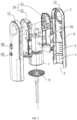
- An electric hair dryer includes a housing, a wind energy generator, a drive control device and a heating device, an elongated channel is formed inside the housing, an air inlet is formed in the housing at one end of the channel, an air outlet is formed on the other end of the channel, a first mounting chamber, a second mounting chamber and a third mounting chamber are provided in the housing from the air inlet to the air outlet successively; the drive control device is mounted in the first mounting chamber, the wind energy generator is mounted in the second mounting chamber, the heating device is mounted in the third mounting chamber, the drive control device is electrically connected to the wind energy generator and the heating device.
- a diversion structure for guiding the heated air flow to the air outlet is provided between the heating device and the air outlet.
- a shock-absorbing sleeve is provided inside the second mounting chamber and positioned between the housing and the wind energy generator.
- An annular groove for accommodating the wind energy generator is provided in an inner ring of the shock-absorbing sleeve.
- a wire groove is provided in the outer wall of the shock-absorbing sleeve along the axial direction.
- a first housing body and a second housing body are each provided with a first arc rib and a second arc rib along the axial direction; and the first arc rib and the second arc rib are positioned circumferentially and form a groove gap extending along the axial direction.
- a protruding portion of the wire groove is inserted in the groove gap to form a stopper in the circumference direction.
- the housing includes a first housing body and a second housing body, the first housing body and the second housing body together define an elongated channel.
- the air inlet is disposed in axial direction with respect to the channel.
- the air inlet is disposed in radial direction with respect to the channel.
- the air outlet is disposed in radial direction with respect to the channel.
- the air inlet and the air outlet of the electric hair dryer are both provided in the housing, and are perpendicular to each other.
- the drive control device, the wind energy generator, the heating device and the diversion structure are all disposed inside the housing.
- the first housing body and the second housing body form the first mounting chamber, the second mounting chamber and the third mounting chamber in a line. That is, the housing of the electric hair dryer is in a continuous cylindrical shape.
- the air outlet is disposed on a radial sidewall of one end. The air flow can act directly on the human hair.
- the shock-absorbing sleeve is made of elastic material.
- the shock-absorbing sleeve is disposed between the housing and the wind energy generator, which makes up the gap therebetween.
- a reacting force is generated to against the vibration force generated by the wind energy generator, which can counteract the majority of the vibration force, so that user feels a softer micro vibration when the hand holds the handle, which improves the comfort degree of the handle.
- two arc plates of the wire groove facilitate hiding the wire after the conductive wire penetration.
- the conductive wire is temporarily restrained in the wire groove, which avoids the interference during mounting.
- the first arc rib 13 and the inner flanging 59 abut against in the annular recess 25, and a hook portion formed by one groove sidewall of the annular recess 25 is inserted in the inner flanging 59 of the shock-absorbing sleeve 54 to realize a sealing connection, so as to prevent the air flow sent into the wind energy generator 7 from lateral leakage.
- a cylindrical protrusion 234 is provided in the second cover body 22.
- the edges of the protrusion 234 and the second cover body 22 are in an arc transition, and the edges form a flow path 235.
- a splitter plate 236 is provided in the second cover body 22 at the position corresponding to the vacancy position 233 of first cover body 21. The splitter plate 236 divides the flow path 235 of the second cover body 22 into two independent portions. A bottom of the splitter plate 236 in the flow path 235 of the second cover body 22 extends to the vacancy position 233 of the first cover body 21.
Landscapes
- Cleaning And Drying Hair (AREA)
Claims (12)
- Elektrischer Haartrockner, umfassend ein Gehäuse (1), ferner umfassend einen Windenergiegenerator (7), eine Antriebssteuerungsvorrichtung und eine Heizvorrichtung (8), wobei ein länglicher Kanal innerhalb des Gehäuses (1) ausgebildet ist, ein Lufteinlass (2) ist in dem Gehäuse (1) an einem Ende des Kanals ausgebildet, ein Luftauslass (3) ist an dem anderen Ende des Kanals ausgebildet; in dem Gehäuse (1) sind hintereinander vom Lufteinlass (2) zum Luftauslass (3) eine erste Montagekammer (4), eine zweite Montagekammer (5) und eine dritte Montagekammer (6) vorgesehen; die Antriebssteuereinrichtung ist in der ersten Montagekammer (4), der Windenergiegenerator (7) ist in der zweiten Montagekammer (5), die Heizeinrichtung (8) ist in der dritten Montagekammer (6) montiert und die Antriebssteuereinrichtung ist mit dem Windenergiegenerator (8) und der Heizeinrichtung (9) elektrisch verbunden;zwischen der Heizvorrichtung (8) und dem Luftauslass (3) ist eine Umleitungsstruktur (23) zur Führung der erwärmten Luft zum Luftauslass (3) vorgesehen;eine stoßdämpfende Hülse (54) ist innerhalb der zweiten Montagekammer (5) vorgesehen und zwischen dem Gehäuse (1) und dem Windenergiegenerator (7) angeordnet; und eine ringförmige Nut (55) zur Aufnahme des Windenergiegenerators (7) ist in einem Innenring der stoßdämpfenden Hülse (54) vorgesehen;eine Drahtnut (57) ist in der Außenwand der stoßdämpfenden Hülse (54) entlang der axialen Richtung vorgesehen;innerhalb der zweiten Montagekammer (5) ist ein erster Gehäusekörper (11) und ein zweiter Gehäusekörper (12) jeweils mit einer ersten Bogenrippe (13) und einer zweiten Bogenrippe (14) entlang der axialen Richtung versehen; die erste Bogenrippe (13) und die zweite Bogenrippe (14) sind in Umfangsrichtung angeordnet und bildeneinen Nutspalt (15), der sich entlang der axialen Richtung erstreckt; und ein vorstehender Abschnitt der Drahtnut (57) ist in den Nutspalt (15) eingesetzt, um einen Anschlag in Umfangsrichtung zu bilden.
- Elektrischer Haartrockner nach Anspruch 1, dadurch gekennzeichnet, dass das Gehäuse (1) einen ersten Gehäusekörper (11) und einen zweiten Gehäusekörper (12) umfasst, und der erste Gehäusekörper (11) und der zweite Gehäusekörper (12) zusammen den länglichen Kanal definieren.
- Elektrischer Haartrockner nach Anspruch 1, dadurch gekennzeichnet, dass der Lufteinlass (2) in axialer Richtung in Bezug auf den Kanal angeordnet ist.
- Elektrischer Haartrockner nach Anspruch 1, dadurch gekennzeichnet, dass der Lufteinlass (2) in radialer Richtung in Bezug auf den Kanal angeordnet ist.
- Elektrischer Haartrockner nach Anspruch 1, dadurch gekennzeichnet, dass die stoßdämpfende Hülse (54) aus elastischem Material hergestellt ist.
- Elektrischer Haartrockner nach Anspruch 1, dadurch gekennzeichnet, dass die vorstehenden Abschnitte an zwei Rändern der Drahtnut (57) jeweils eine Bogenplatte (58) umfassen, die in radialer Richtung nach außen vorsteht, und dass zwei Bogenplatten (58) halb geschlossen um den Nutrand der Drahtnut (57) gewickelt sind.
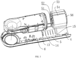
- Elektrischer Haartrockner nach Anspruch 1, dadurch gekennzeichnet, dass der Windenergiegenerator (7) einen Mikromotor (51) und ein von dem Mikromotor (51) angetriebenes Windrotorblatt (52) umfasst, dass ein Hülsenring (53) außerhalb des Mikromotors (51) vorgesehen ist; dass das Windrotorblatt (52) auf der Hauptwelle des Mikromotors (51) montiert ist; dass der Hülsenring (53) außerhalb des Motors angebracht ist und sich in Richtung eines Außenrings des Windrotorblatts (52) erstreckt; dass der Flügelaußenring des Windrotorblatts (52) mit Spiel in der Innenwand des Hülsenrings (53) angeordnet ist; und der Hülsenring (53) des Windenergiegenerators (7) in die ringförmige Nut (55) der stoßdämpfenden Hülse (54) eingesetzt ist.
- Elektrischer Haartrockner nach Anspruch 7, dadurch gekennzeichnet, dass die ersten Bogenrippen (13) an der Vorder- bzw. Rückseite der zweiten Montagekammer (5) in axialer Richtung angeordnet sind; dass die zweiten Bogenrippen (14) in Abständen zwischen den ersten Bogenrippen (13) an der Vorder- bzw. Rückseite angeordnet sind; dass eine ringförmige Klemmnut (66) an der Außenkante eines Endes der stoßdämpfenden Hülse (54) vorgesehen ist; dass die Nuttiefe der ringförmigen Klemmnut (56) an die erste Bogenrippe (13) angepasst ist; und ein Ende der stoßdämpfenden Hülse (54) in eine erste Bogenrippe (13) eingesetzt ist, und das andere Ende an der Endfläche der anderen ersten Bogenrippe (13) anliegt.
- Elektrischer Haartrockner nach Anspruch 8, dadurch gekennzeichnet, dass die Heizeinrichtung (8) an der Rückseite des Luftaustritts des Windenergiegenerators (7) angeordnet ist; in diesem Bereich ist eine wärmeisolierende Abdeckung (20) im Inneren des Gehäuses (1) vorgesehen; die Umlenkstruktur (23) ist auf der wärmeisolierenden Abdeckung (20) angeordnet; die wärmeisolierende Abdeckung (20) umfasst einen ersten Abdeckungskörper (21) und einen zweiten Abdeckungskörper (22), die voneinander getrennt sind; eine ringförmige Aussparung (25) ist auf einer Seite der wärmeisolierenden Abdeckung (20) an dem Windenergiegenerator (7) vorgesehen; bei der Montage des ersten Abdeckungskörpers (21) und des zweiten Abdeckungskörpers (22) werden der erste Abdeckungskörper (21) und der zweite Abdeckungskörper (22) durch die ringförmige Ausnehmung (25) in die erste Bogenrippe (13) eingesetzt; eine innere Aufhängung (59) ist an einer Seite der Endfläche der stoßdämpfenden Hülse (54) vorgesehen, die an der ersten Bogenrippe (13) anliegt; die erste Bogenrippe (13) und die innere Aufhängung (59) liegen an einer Innenseite der ringförmigen Aussparung (25) an, und ein Hakenabschnitt, der von einer Nutenseitenwand der ringförmigen Aussparung (25) gebildet wird, ist in die innere Aufhängung (59) der stoßdämpfenden Hülse (54) eingeführt, um eine Dichtungsverbindung zu realisieren.
- Elektrischer Haartrockner nach Anspruch 1, dadurch gekennzeichnet, dass die Heizvorrichtung (8) eine einen rechteckigen Rahmen bildende Tragplatte (81), einen innerhalb des rechteckigen Rahmens angeordneten Tragrahmen und einen im Tragrahmen vorgesehenen Heizdraht umfasst; der Tragrahmen umfasst einander kreuzweise überlappende Tragplatten (82) und einen durch den Spalt zwischen den Tragplatten (82) gebildeten Warmluftkanal; mehrere Nuten (83) sind in einem Außenring der Trägerplatte (82) vorgesehen; der gewickelte Heizdraht ist in die Nut (83) eingeführt und in dem Warmluftkanal angeordnet; ein positiver Anschluss und ein negativer Anschluss sind in dem Tragrahmen vorgesehen, die zwei Enden des Heizdrahtes entsprechen; und der Anschluss ist elektrisch mit der Antriebssteuervorrichtung über einen leitenden Draht verbunden und eine Sicherung ist in einem Verbindungsabschnitt eines Anschlusses vorgesehen.
- Elektrischer Haartrockner nach Anspruch 9, dadurch gekennzeichnet, dass die Umlenkstruktur (23) eine Umlenköffnung (231) umfasst, die an dem ersten Abdecckörper (21) angeordnet ist und mit dem Luftauslass (3) in Verbindung steht; die Umlenköffnung (231) befindet sich neben dem Luftauslass (3); eine Vielzahl der Umlenkplatten (232) ist in der Innenwand der Umlenköffnung (231) entlang der Umfangsrichtung vorgesehen; die Umlenkplatten (232) erstrecken sich entlang der Radialrichtung und sind gleichmäßig entlang der Umfangsrichtung verteilt angeordnet; eine Leerstellenposition (233) ist an einem hinteren Ende der Umlenköffnung (231) vorgesehen; ein zylindrischer Vorsprung (234) ragt in den zweiten Abdeckungskörper (22) hinein; die Kanten des Vorsprungs (234) und des zweiten Abdeckungskörpers (22) befinden sich in einem bogenförmigen Übergang und bilden einen Strömungsweg (235); eine Verteilerplatte (236) ist in dem zweiten Abdeckungskörper (22) an der Position vorgesehen, die der freien Position (233) des ersten Abdeckungskörpers (21) entspricht; die Teilerplatte (236) unterteilt den Abflussweg (235) des zweiten Abdeckkörpers (22) in zwei unabhängige Abschnitte; und ein Boden der Teilerplatte (236) im Abflussweg (235) des zweiten Abdeckkörpers (22) erstreckt sich bis zur freien Position (233) des ersten Abdeckkörpers (21).
- Elektrischer Haartrockner nach Anspruch 11, dadurch gekennzeichnet, dass der erste Abdeckkörper (21) in der Richtung von der Heizvorrichtung (8) zur Umlenköffnung (231) allmählich vertieft ist, so dass der Raum des Abflussweges (235), der durch den ersten Abdeckkörper (21) und den zweiten Abdeckkörper (22) gebildet wird, stark reduziert ist.
Applications Claiming Priority (2)
| Application Number | Priority Date | Filing Date | Title |
|---|---|---|---|
| CN201910870953.6A CN110477573B (zh) | 2019-09-16 | 2019-09-16 | 电吹风 |
| PCT/CN2020/115296 WO2021052320A1 (zh) | 2019-09-16 | 2020-09-15 | 电吹风 |
Publications (4)
| Publication Number | Publication Date |
|---|---|
| EP4014784A1 EP4014784A1 (de) | 2022-06-22 |
| EP4014784A4 EP4014784A4 (de) | 2022-10-26 |
| EP4014784B1 true EP4014784B1 (de) | 2025-07-02 |
| EP4014784C0 EP4014784C0 (de) | 2025-07-02 |
Family
ID=68558070
Family Applications (1)
| Application Number | Title | Priority Date | Filing Date |
|---|---|---|---|
| EP20865230.5A Active EP4014784B1 (de) | 2019-09-16 | 2020-09-15 | Elektrischer haartrockner |
Country Status (5)
| Country | Link |
|---|---|
| US (1) | US12383041B2 (de) |
| EP (1) | EP4014784B1 (de) |
| JP (1) | JP7437076B2 (de) |
| CN (1) | CN110477573B (de) |
| WO (1) | WO2021052320A1 (de) |
Families Citing this family (15)
| Publication number | Priority date | Publication date | Assignee | Title |
|---|---|---|---|---|
| CN110477573B (zh) * | 2019-09-16 | 2021-08-17 | 深圳市物种起源科技有限公司 | 电吹风 |
| CN111248597A (zh) * | 2020-03-31 | 2020-06-09 | 深圳奥郎格环保有限公司 | 吹风机 |
| CN114052371B (zh) * | 2020-08-04 | 2024-07-19 | 杭州乐秀电子科技有限公司 | 一种气流倍增头发护理器具 |
| CN114073366B (zh) * | 2020-08-17 | 2024-06-18 | 杭州乐秀电子科技有限公司 | 一种人体工程学头发护理器具 |
| CN114073365B (zh) * | 2020-08-17 | 2024-06-18 | 杭州乐秀电子科技有限公司 | 一种低损耗头发护理器具 |
| CN114190676A (zh) * | 2020-12-28 | 2022-03-18 | 杭州乐秀电子科技有限公司 | 一种体感温度低的飓风筒 |
| CN114190677A (zh) * | 2020-12-28 | 2022-03-18 | 杭州乐秀电子科技有限公司 | 一种工作可靠的飓风筒 |
| CN114190683B (zh) * | 2020-12-28 | 2024-08-20 | 杭州乐秀电子科技有限公司 | 一种装配方便的飓风筒 |
| CN114190678A (zh) * | 2020-12-28 | 2022-03-18 | 杭州乐秀电子科技有限公司 | 一种新型飓风筒 |
| CN114190679A (zh) * | 2020-12-28 | 2022-03-18 | 杭州乐秀电子科技有限公司 | 一种装配可靠的飓风筒 |
| CN114190680B (zh) * | 2021-01-21 | 2024-08-20 | 杭州乐秀电子科技有限公司 | 一种防烫飓风筒 |
| JP7712096B2 (ja) * | 2021-03-30 | 2025-07-23 | シャープ株式会社 | ヘアドライヤ |
| CN113498922B (zh) * | 2021-08-15 | 2024-07-02 | 苏州小枣树网络科技有限公司 | 一种手持吹风机 |
| USD1039762S1 (en) * | 2023-04-14 | 2024-08-20 | Shenzhen Xiaoti Dazuo Technology Co., Ltd. | Blow dryer |
| CN117064152B (zh) * | 2023-08-08 | 2024-08-30 | 东莞市比迪电器有限公司 | 一种多功能高速吹风机及控制方法 |
Family Cites Families (13)
| Publication number | Priority date | Publication date | Assignee | Title |
|---|---|---|---|---|
| BE1003904A6 (fr) * | 1990-03-02 | 1992-07-14 | Faco Sa | Seche-cheveux de voyage. |
| RU2206792C2 (ru) * | 2000-05-31 | 2003-06-20 | Халаев Григорий Григорьевич | Устройство амортизатора электроцентробежного насоса в скважине |
| KR101229109B1 (ko) * | 2011-01-21 | 2013-02-05 | (주)엠파워텍 | 헤어 드라이어 |
| GB2515813B (en) * | 2013-07-05 | 2017-07-05 | Dyson Technology Ltd | A handheld appliance |
| GB2521145B (en) * | 2013-12-10 | 2016-04-13 | Dyson Technology Ltd | A hand held appliance |
| CN206062462U (zh) * | 2016-06-24 | 2017-04-05 | 绍兴市聚祥电器科技有限公司 | 电吹风旋转式聚风嘴 |
| CN108851462A (zh) * | 2017-05-09 | 2018-11-23 | 深圳市物种起源科技有限公司 | 手持电吹风 |
| CN207506112U (zh) * | 2017-11-27 | 2018-06-19 | 吕璟赟 | 一种新型吹风机 |
| CN209185835U (zh) * | 2018-08-23 | 2019-08-02 | 深圳市物种起源科技有限公司 | 一种吹风机的新型风道 |
| CN109512119A (zh) * | 2018-11-28 | 2019-03-26 | 中山市瑞驰泰克电子有限公司 | 一种梳齿电吹风 |
| CN109452744B (zh) * | 2018-12-06 | 2020-09-29 | 舒可士(深圳)科技有限公司 | 便于手持的毛发干燥装置 |
| CN110150827B (zh) * | 2019-06-17 | 2024-05-10 | 嘉兴市资格电气科技股份有限公司 | 电吹风 |
| CN110477573B (zh) * | 2019-09-16 | 2021-08-17 | 深圳市物种起源科技有限公司 | 电吹风 |
-
2019
- 2019-09-16 CN CN201910870953.6A patent/CN110477573B/zh active Active
-
2020
- 2020-09-15 WO PCT/CN2020/115296 patent/WO2021052320A1/zh not_active Ceased
- 2020-09-15 JP JP2022515577A patent/JP7437076B2/ja active Active
- 2020-09-15 EP EP20865230.5A patent/EP4014784B1/de active Active
-
2022
- 2022-03-15 US US17/694,742 patent/US12383041B2/en active Active
Also Published As
| Publication number | Publication date |
|---|---|
| CN110477573B (zh) | 2021-08-17 |
| JP2022547188A (ja) | 2022-11-10 |
| US12383041B2 (en) | 2025-08-12 |
| CN110477573A (zh) | 2019-11-22 |
| JP7437076B2 (ja) | 2024-02-22 |
| US20220192341A1 (en) | 2022-06-23 |
| WO2021052320A1 (zh) | 2021-03-25 |
| EP4014784C0 (de) | 2025-07-02 |
| EP4014784A1 (de) | 2022-06-22 |
| EP4014784A4 (de) | 2022-10-26 |
Similar Documents
| Publication | Publication Date | Title |
|---|---|---|
| EP4014784B1 (de) | Elektrischer haartrockner | |
| CN209732888U (zh) | 一种工作可靠的电吹风 | |
| KR20200051513A (ko) | 히터 및 모발 건조장치 | |
| CN209750149U (zh) | 一种双驱动电吹风 | |
| US20200128937A1 (en) | Heater and hair drying apparatus | |
| CN104456936A (zh) | 暖风装置 | |
| CN209171521U (zh) | 毛发干燥装置 | |
| CN210581446U (zh) | 干发器的发热装置及干发器 | |
| CN216568809U (zh) | 毛发干燥用具 | |
| CN216568807U (zh) | 毛发护理器 | |
| CN210809674U (zh) | 减震套、风能发生装置的安装结构和吹风机 | |
| CN116098361B (zh) | 毛发护理器 | |
| CN212117386U (zh) | 风嘴组件及手持吹风机 | |
| CN210696417U (zh) | 一种电吹风 | |
| CN220068538U (zh) | 宠物吹风梳组件 | |
| CN217266537U (zh) | 一种蒸汽发生器及挂烫机 | |
| CN213908942U (zh) | 电吹风 | |
| CN116098366B (zh) | 毛发护理器 | |
| EP3112772B1 (de) | Lüftervorrichtung mit einem vorwärmezirkuationskanal | |
| CN213344661U (zh) | 一种便携式电风机 | |
| CN222928503U (zh) | 加热器及电吹风 | |
| CN222548734U (zh) | 一种热风梳 | |
| CN218328678U (zh) | 发热体组件及吹风机 | |
| CN217635853U (zh) | 一种电暖器 | |
| CN209331292U (zh) | 过温保护结构及毛发干燥装置 |
Legal Events
| Date | Code | Title | Description |
|---|---|---|---|
| STAA | Information on the status of an ep patent application or granted ep patent |
Free format text: STATUS: THE INTERNATIONAL PUBLICATION HAS BEEN MADE |
|
| PUAI | Public reference made under article 153(3) epc to a published international application that has entered the european phase |
Free format text: ORIGINAL CODE: 0009012 |
|
| STAA | Information on the status of an ep patent application or granted ep patent |
Free format text: STATUS: REQUEST FOR EXAMINATION WAS MADE |
|
| 17P | Request for examination filed |
Effective date: 20220317 |
|
| AK | Designated contracting states |
Kind code of ref document: A1 Designated state(s): AL AT BE BG CH CY CZ DE DK EE ES FI FR GB GR HR HU IE IS IT LI LT LU LV MC MK MT NL NO PL PT RO RS SE SI SK SM TR |
|
| STAA | Information on the status of an ep patent application or granted ep patent |
Free format text: STATUS: EXAMINATION IS IN PROGRESS |
|
| A4 | Supplementary search report drawn up and despatched |
Effective date: 20220926 |
|
| RIC1 | Information provided on ipc code assigned before grant |
Ipc: A45D 20/12 20060101ALI20220920BHEP Ipc: A45D 20/10 20060101AFI20220920BHEP |
|
| 17Q | First examination report despatched |
Effective date: 20221007 |
|
| DAV | Request for validation of the european patent (deleted) | ||
| DAX | Request for extension of the european patent (deleted) | ||
| GRAP | Despatch of communication of intention to grant a patent |
Free format text: ORIGINAL CODE: EPIDOSNIGR1 |
|
| STAA | Information on the status of an ep patent application or granted ep patent |
Free format text: STATUS: GRANT OF PATENT IS INTENDED |
|
| INTG | Intention to grant announced |
Effective date: 20250128 |
|
| GRAS | Grant fee paid |
Free format text: ORIGINAL CODE: EPIDOSNIGR3 |
|
| GRAA | (expected) grant |
Free format text: ORIGINAL CODE: 0009210 |
|
| STAA | Information on the status of an ep patent application or granted ep patent |
Free format text: STATUS: THE PATENT HAS BEEN GRANTED |
|
| AK | Designated contracting states |
Kind code of ref document: B1 Designated state(s): AL AT BE BG CH CY CZ DE DK EE ES FI FR GB GR HR HU IE IS IT LI LT LU LV MC MK MT NL NO PL PT RO RS SE SI SK SM TR |
|
| REG | Reference to a national code |
Ref country code: GB Ref legal event code: FG4D |
|
| REG | Reference to a national code |
Ref country code: CH Ref legal event code: EP |
|
| REG | Reference to a national code |
Ref country code: DE Ref legal event code: R096 Ref document number: 602020053978 Country of ref document: DE |
|
| REG | Reference to a national code |
Ref country code: IE Ref legal event code: FG4D |
|
| U01 | Request for unitary effect filed |
Effective date: 20250729 |
|
| U07 | Unitary effect registered |
Designated state(s): AT BE BG DE DK EE FI FR IT LT LU LV MT NL PT RO SE SI Effective date: 20250804 |
|
| PGFP | Annual fee paid to national office [announced via postgrant information from national office to epo] |
Ref country code: GB Payment date: 20250919 Year of fee payment: 6 |
|
| U20 | Renewal fee for the european patent with unitary effect paid |
Year of fee payment: 6 Effective date: 20250924 |
|
| PG25 | Lapsed in a contracting state [announced via postgrant information from national office to epo] |
Ref country code: IS Free format text: LAPSE BECAUSE OF FAILURE TO SUBMIT A TRANSLATION OF THE DESCRIPTION OR TO PAY THE FEE WITHIN THE PRESCRIBED TIME-LIMIT Effective date: 20251102 |
|
| PG25 | Lapsed in a contracting state [announced via postgrant information from national office to epo] |
Ref country code: NO Free format text: LAPSE BECAUSE OF FAILURE TO SUBMIT A TRANSLATION OF THE DESCRIPTION OR TO PAY THE FEE WITHIN THE PRESCRIBED TIME-LIMIT Effective date: 20251002 |
|
| PG25 | Lapsed in a contracting state [announced via postgrant information from national office to epo] |
Ref country code: HR Free format text: LAPSE BECAUSE OF FAILURE TO SUBMIT A TRANSLATION OF THE DESCRIPTION OR TO PAY THE FEE WITHIN THE PRESCRIBED TIME-LIMIT Effective date: 20250702 |