EP4014784A1 - Elektrischer haartrockner - Google Patents
Elektrischer haartrockner Download PDFInfo
- Publication number
- EP4014784A1 EP4014784A1 EP20865230.5A EP20865230A EP4014784A1 EP 4014784 A1 EP4014784 A1 EP 4014784A1 EP 20865230 A EP20865230 A EP 20865230A EP 4014784 A1 EP4014784 A1 EP 4014784A1
- Authority
- EP
- European Patent Office
- Prior art keywords
- cover body
- hair dryer
- electric hair
- housing
- dryer according
- Prior art date
- Legal status (The legal status is an assumption and is not a legal conclusion. Google has not performed a legal analysis and makes no representation as to the accuracy of the status listed.)
- Granted
Links
Images


Classifications
-
- A—HUMAN NECESSITIES
- A45—HAND OR TRAVELLING ARTICLES
- A45D—HAIRDRESSING OR SHAVING EQUIPMENT; EQUIPMENT FOR COSMETICS OR COSMETIC TREATMENTS, e.g. FOR MANICURING OR PEDICURING
- A45D20/00—Hair drying devices; Accessories therefor
- A45D20/04—Hot-air producers
- A45D20/08—Hot-air producers heated electrically
- A45D20/10—Hand-held drying devices, e.g. air douches
- A45D20/12—Details thereof or accessories therefor, e.g. nozzles, stands
-
- A—HUMAN NECESSITIES
- A45—HAND OR TRAVELLING ARTICLES
- A45D—HAIRDRESSING OR SHAVING EQUIPMENT; EQUIPMENT FOR COSMETICS OR COSMETIC TREATMENTS, e.g. FOR MANICURING OR PEDICURING
- A45D20/00—Hair drying devices; Accessories therefor
- A45D20/04—Hot-air producers
- A45D20/08—Hot-air producers heated electrically
- A45D20/10—Hand-held drying devices, e.g. air douches
Definitions
- the present application relates to a field of hair drying device and in particular, relates to an electric hair dryer.
- An electric hair dryer is a commonly used household appliance, mainly used for hair drying and shaping. In addition, it can also be used for local drying, heating and physiotherapy in a laboratory, a physiotherapy room, industrial production, art designing and others, having a wide application.
- the handle portion and the main body of the electric hair dryer are mostly integrated with each other.
- the handle can also be designed to be bendable for storage. However, the whole structure is still not compact enough.
- the present application provides an electric hair dryer, in which individual function modules are integrated in a cylindrical housing, providing the advantages of compactness and portability.
- the present application is realized by adopting the following technical solution.
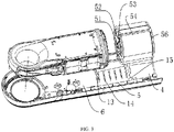
- An electric hair dryer includes a housing, an elongated channel is formed inside the housing, an air inlet is formed in the housing at one end of the channel, an air outlet is formed on the other end of the channel, a first mounting chamber, a second mounting chamber and a third mounting chamber are provided in the housing from the air inlet to the air outlet successively, a drive control device is mounted in the first mounting chamber, a wind energy generator is mounted in the second mounting chamber, a heating device is mounted in the third mounting chamber, and the drive control device is electrically connected to the wind energy generator and the heating device.
- a diversion structure for guiding the heated air flow to the air outlet is provided between the heating device and the air outlet. The heating device provides heat for the air generated by the wind energy generator.
- the housing includes a first housing body and a second housing body, the first housing body and the second housing body together define an elongated channel.
- the air inlet is disposed in axial direction with respect to the channel.
- the air inlet is disposed in radial direction with respect to the channel.
- the air outlet is disposed in radial direction with respect to the channel.
- the air inlet and the air outlet of the electric hair dryer are both provided in the housing, and are perpendicular to each other.
- the drive control device, the wind energy generator, the heating device and the diversion structure are all disposed inside the housing.
- the first housing body and the second housing body form the first mounting chamber, the second mounting chamber and the third mounting chamber in a line. That is, the housing of the electric hair dryer is in a continuous cylindrical shape.
- the air outlet is disposed on a radial sidewall of one end. The air flow can act directly on the human hair.
- a shock-absorbing sleeve is provided inside the second mounting chamber and is positioned between the housing and the wind energy generator.
- An annular groove for accommodating the wind energy generator is provided in an inner ring of the shock-absorbing sleeve.
- the shock-absorbing sleeve is made of elastic material.
- a wire groove is provided in the outer wall of the shock-absorbing sleeve along the axial direction.
- the shock-absorbing sleeve is disposed between the housing and the wind energy generator, which makes up the gap therebetween.
- a reacting force is generated to against the vibration force generated by the wind energy generator, which can counteract the majority of the vibration force, so that user feels a softer micro vibration when the hand holds the handle, which improves the comfort degree of the handle.
- the first housing body and the second housing body are each provided with a first arc rib and a second arc rib along the axial direction.
- the first arc rib and the second arc rib are distributed along circumference and forms a groove gap extending along the axial direction.
- a protruding portion of the wire groove is inserted in the groove gap to form a stopper in the circumference direction.
- the first arc rib and the second arc rib can form a mounting area for accommodating the shock-absorbing sleeve.
- the first arc rib and the second arc rib can form a mounting area for accommodating the shock-absorbing sleeve.
- the groove gap and the protruding portion of the wire groove forms an insertion stopper, which makes the shock-absorbing sleeve more stable after fixing.
- the protruding portions on two edges of the wire groove each include an arc plate protruding to the outside along the radial direction. Two arc plates are wrapped around the groove edge of the wire groove in a semi-closed way.
- the wire groove is used for the penetration of the conductive wire, and the wire groove can be closed when bearing external pressure.
- two arc plates of the wire groove facilitate hiding the wire after the conductive wire penetration.
- the conductive wire is temporarily restrained in the wire groove, which avoids the interference during mounting.
- the wind energy generator includes a micro motor and a wind blade driven by the micro motor, a sleeve ring is provided outside the micro motor.
- the wind blade is mounted on the main shaft of the micro motor.
- the sleeve ring is mounted outside the motor and extends to an outer ring of the wind blade.
- the blade outer ring of the wind blade is in a clearance fit with the inner wall of the sleeve ring.
- the sleeve ring of the wind energy generator is inserted in the annular ring of the shock-absorbing sleeve.
- the mounting structure of the micro motor and the wind blade form an integrated structure after optimization, which is hidden inside the sleeve ring.
- the main body is inserted in the annular groove of the shock-absorbing sleeve through sleeve ring.
- annular clamping groove is provided on the outer edge of one end of the shock-absorbing sleeve.
- the groove depth of the annular clamping groove is adapted to the first arc rib.
- One end of the shock-absorbing sleeve is inserted in one first arc rib, and the other end abuts against on the end surface of the other first arc rib.
- one end of the shock-absorbing sleeve is inserted in one first arc rib through the annular clamping groove, and the other end abuts against on the end surface of the other first arc rib, so as to form an insertion stopper.
- the heating device is positioned at the rear of the air output of the wind energy generator.
- a heat insulation cover is provided inside the housing; the diversion structure is disposed on the heat insulation flamen retardant cover.
- the heat insulation cover includes a first cover body and a second cover body, which are separated from each other.
- An annular recess is provided on one side of the heat insulation cover at the wind energy generator.
- the first arc rib and the inner flanging abut against in the annular recess, and a hook portion formed by one groove sidewall of the annular recess is inserted in the inner flanging of the shock-absorbing sleeve to realize a sealing connection.
- a heat insulation cover is provided at the rear of the wind energy generator.
- the heat insulation cover is hermetically sleeved on the wind energy generator, so as to ensure a full use of the wind energy generated by the win energy generator.
- the heating device includes a bearing plate enclosing a rectangular frame, a supporting frame positioned inside the rectangular frame and a heating wire provided in the supporting frame.
- the supporting frame includes supporting plates crossly overlapped with each other and a warm air channel formed by the distance between the supporting plates.
- a plurality of grooves are provided in an outer ring of the supporting plate.
- the coiled heating wire is inserted in the groove and is positioned in the warm wind channel.
- a positive terminal and a negative terminal are provided in the supporting frame, which are corresponding to two ends of the heating wire respectively.
- the terminal is electrically connected to the drive control device through conductive wire, and a fuse is added in a connection section of one terminal.
- the diversion structure includes a diversion opening disposed on the first cover body, which is communicated with the air outlet.
- the diversion opening is adapted to the air outlet.
- a plurality of the diversion plates are provided in the inner wall of the diversion opening along the circumference direction.
- the diversion plates extend along the radial direction and are in an equidistant distribution along circumference direction.
- a vacancy position is provided on a tail end of the diversion opening.
- a protrusion protruding as a cylindrical shape is provided in the second cover body.
- the edges of the protrusion and the second cover body are in an arc transition, and the edges form a flow path.
- a splitter plate is provided in the second cover body at the position corresponding to the vacancy position of first cover body. The splitter plate divides the flow path of the second cover body into two independent portions. A bottom of the splitter plate in the flow path of the second cover body extends to the vacancy position of the first cover body.
- the diversion structure diverts the air out appropriately by the structure thereof.
- first cover body is gradually shrunk in the direction from the heating device to the diversion opening, so that the space of the flow path formed by the first cover body and the second cover body is slumped.
- the air flow generated by the wind energy generator flows through the heating device and collects in the flow path.
- the air flow generated by the wind energy generator enters the flow path through the heater, and the diversion plates in the flow path stop the air flow.
- the air pressure is increased and two short and powerful air flows are formed, and divert evenly out through the splitter plates in the diversion direction of the diversion plate.
- splitter plate 24. stopping block; 25. annular recess; 26. fourth mounting chamber; 51. micro motor; 52. wind blade; 53. sleeve ring; 54. shock-absorbing sleeve; 55. annular groove; 56. annular clamping groove; 57. wire groove; 58. arc plate; and 59. inner flanging.
- an electric hair dryer includes a housing 1.
- the housing 1 is an integrated housing and an elongated channel such as is formed therein, such as cylindrical, rectangular, or similarly shaped channel.
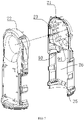
- the housing 1 includes a first housing body 11 and a second housing body 12.
- the first housing body 11 is in snap connection with the second housing body 12.
- the first housing body 11 and the second housing body 12 form an elongated channel, such as a cylindrical channel.
- An air inlet 2 is formed in the housing 1 at one end of the channel. In some embodiments, the air inlet 2 is disposed in axial direction with respect to the channel, as shown in FIG.2 .
- the air inlet 2 is disposed in radial direction with respect to the channel, for example, disposed in the sidewall of the housing 1.
- a cover plate 9 with a plurality holes is mounted at the air inlet 2. The cover plate 9 can close the air inlet 2 and the air flow can penetrate through the holes of the cover plate 9.
- An air outlet 3 disposed in radial direction is formed on the other end of the housing 1.
- the air outlet 3 is positioned in the first housing 11 and is communicated with the channel.
- a first mounting chamber 4, a second mounting chamber 5 and a third mounting chamber 6 is independently provided in the housing 1 from the air inlet side 2 to the air outlet side 3 successively.
- a drive control device is mounted in the first mounting chamber 4 (not shown in the figure).
- the wind energy generator 7 is mounted in the second mounting chamber.
- a heating device 8 for providing heat for the wind energy generator 7 is mounted in the third mounting chamber.
- the drive control device is electrically connected to the wind energy generator 7 and the heating device 8 through a conductive wire.
- a plurality of threaded columns are provided in the first housing body 11 of the first mounting chamber 4.
- the drive control device is fixed on the threaded column in the first mounting chamber 4 via a fastener.
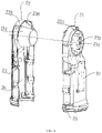
- the first housing body 11 and the second housing body 12 are each provided with a first arc rib 13 and a second arc rib 14 along the axial direction.
- the first arc rib 13 and the second arc rib 14 are distributed along circumference of the housing 1.
- the first arc ribs 13 are positioned at the front and rear sides of the second mounting chamber 5 along axial direction respectively.
- the second arc rib 14 is positioned between the first arc ribs 13 at the front and the rear sides respectively.
- the inner arc surfaces of the first arc ribs in the first housing body 11 and the second housing body 12 form a concentric circle along the circumference direction.
- the inner arc surfaces of the second arc ribs also form a concentric circle along the circumference direction.
- the concentric circle formed by the second arc ribs 14 has a smaller diameter than the concentric circle formed by the first arc ribs 13.
- the wind energy generator 7 is inserted in the area formed by the first arc rib 13 and the second arc rib 14.
- the wind energy generator 7 includes a micro motor 51 and a wind blade 52 driven by the micro motor 51.
- a sleeve ring 53 is provided outside the micro motor 51.
- the wind blade 52 is mounted on the main shaft of the micro motor 51.
- the sleeve ring 53 is mounted at the outside of the motor and extends to an outer ring of the wind blade 52.
- the blade outer ring of the wind blade 52 is in a clearance fit with the inner wall of the sleeve ring 53.
- a shock-absorbing sleeve 54 made of elastic material is provided between the sleeve ring 53 and the housing 1.
- the shock-absorbing sleeve 54 can be made of rubber or silica gel, and has a certain thickness to ensure a sufficient damping effect.
- the micro motor 51 is sleeved and mounted in the shock-absorbing sleeve 54.
- An annular groove 55 for accommodating the sleeve ring 53 is provided in an inner ring of the shock-absorbing sleeve 54.
- the shock-absorbing sleeve 54 has a certain elasticity.
- the micro motor 51 is inserted and wrapped in the annular groove 55.
- An annular clamping groove 56 is provided on the outer edge of one end of the shock-absorbing sleeve 54.
- the groove depth of the annular clamping groove 56 is adapted to the first arc rib 13.
- the first arc rib 13 and the second arc rib 14 are distributed along circumference of the housing 1 and forms a groove gap 15 extending along the axial direction on the inner walls of the first housing body 11 and the second housing body 12.
- a wire groove 57 is provided in the outer wall of the shock-absorbing sleeve 54 along the axial direction. Two edges of the wire groove 57 each provides with an arc plate 58 protruding outwardly along the radial direction. Two arc plates 58 are wrapped around the groove edge of the wire groove 57, and are disposed as semi-closed. The wire groove is used for the penetration of the conductive wire.
- the wire groove 57 can be closed when two arc plates 58 are pressed.
- the protrusion portions of two arc plates are inserted in the groove gap 15 of the first housing body 11 or the second housing body 12, so as to form a limit in the circumference direction.
- the heating device is positioned at the rear of the air output of the wind energy generator 7.
- a heat insulation cover 20 is provided inside the housing 1.
- the heat insulation cover 20 is made of a blend of PA and glass fiber.
- the heat insulation cover 20 includes a first cover body 21 and a second cover body 22.
- the first cover body 21 is fixed with the second cover body 22 through the threaded column and the screw.
- the first cover body 21 is inserted in the first housing body 11.
- the heat insulation cover 20 includes a fourth mounting chamber 26 for accommodating the heating device 8 and a diversion structure 23 for guiding the heated air flow to the air outlet 3.
- a stopping block 24 is provided on the boundary of the fourth mounting chamber 26 and the diversion structure 23.
- the heating device 8 is limited in the fourth mounting chamber 26, which avoids the displacement of the heating device 8 towards the air outlet 3.
- An annular recess 25 is provided on one side of the heat insulation cover 20 at the wind energy generator.
- the first cover body 21 and the second cover body 22 are inserted in the first arc rib 13 through the annular recess 25.
- An inner flanging 59 is provided on one side of the end surface of the shock-absorbing sleeve 54 abutting against the first arc rib 13.
- the first arc rib 13 and the inner flanging 59 abut against in the annular recess 25, and a hook portion formed by one groove sidewall of the annular recess 25 is inserted in the inner flanging 59 of the shock-absorbing sleeve 54 to realize a sealing connection, so as to prevent the air flow sent into the wind energy generator 7 from lateral leakage.
- the heating device 8 includes a bearing plate 81 forming a rectangular frame, a supporting frame positioned inside the rectangular frame and a heating wire provided in the supporting frame.
- the supporting frame includes supporting plates 82 crossly overlapped with each other and a warm air channel formed by the gap between the supporting plates 82.
- a plurality of grooves 83 are provided in an outer ring of the supporting plate 82.
- the coiled heating wire is inserted in the groove 83 and is positioned in the warm wind channel.
- a positive terminal and a negative terminal are provided in the supporting frame, which are corresponding to two ends of the heating wire respectively.
- the terminal is electrically connected to the drive control device through conductive wire, and a fuse is added in a connection section of one terminal (the portion being shielded is not shown).
- the bearing plate 81 and the supporting plate 82 are both made of connected mica sheets, which have the functions of insulation and thermal resistance achieving low loss.
- the bearing plate 81 includes four main portions capable of being independently bended. After bending to form a rectangular frame, it is attached to the outside of the supporting frame and bonded with high-temperature resistant tape. In order to ensure safety, a layer of asbestos net is provided between the rectangular frame and the heat insulation cover 20 for flame retardant protection. In addition, the asbestos net can disperse the heat on the bearing plate 81 to achieve the effect of heat dissipation.
- a temperature control module is provided inside the first housing body 11.
- the temperature control module includes a circuit board 91, and a temperature control switch 92 electrically connected to the circuit board 91 for controlling the opening and closing of the heating device 8.
- the circuit board 91 is electrically connected to the drive control device.
- the circuit board 91 is positioned between the first housing body 11 and the first cover body 21.
- the circuit board 91 is mounted on the first housing body 11 through screw.
- a sensor 93 is provided on the circuit board 91.
- the sensor 93 can be a temperature sensor or a humidity/temperature sensor.
- a penetrating through hole 94 is provided at the position of the first cover body 21 close to the air inlet 2.
- the sensor 93 extends out of the through hole 94 to detect the temperature and/or humidity at the air outlet 2.
- a power switch 95 for controlling the opening of the wind energy generator 7 is provided in the second housing 12, and an air volume adjusting switch 96 for controlling the rotating speed of the wind energy generator 7 is also included.
- the power source is electrically connected to the air volume adjusting switch 96 and the drive control device.
- the diversion structure 23 for guiding the air flow to the air outlet 3 includes a diversion opening 231 disposed on the first cover body 2 and communicated with the air outlet 3.
- the diversion opening 231 is adj acent to the air outlet 3.
- a plurality of the diversion plates 232 are provided in the inner wall of the diversion opening 231 along the circumference direction.
- the diversion plates 232 extend along the radial direction and are in an equidistant distribution along circumference direction.
- a vacancy position 233 without the diversion plate 232 is provided at a tail end of the diversion opening 231.
- a cylindrical protrusion 234 is provided in the second cover body 22.
- the edges of the protrusion 234 and the second cover body 22 are in an arc transition, and the edges form a flow path 235.
- a splitter plate 236 is provided in the second cover body 22 at the position corresponding to the vacancy position 233 of first cover body 21. The splitter plate 236 divides the flow path 235 of the second cover body 22 into two independent portions. A bottom of the splitter plate 236 in the flow path 235 of the second cover body 22 extends to the vacancy position 233 of the first cover body 21.
- the first cover body 21 is gradually shrunk in the direction from the heating device 8 to the diversion opening 231, so that the space of the flow path 235 formed by the first cover body 21 and the second cover body 22 is greatly reduced.
- the air flow generated by the wind energy generator 7 flows through the heating device 8 and collects in the flow path 235.
- the air flow generated by the wind energy generator 7 enters the flow path 235 through the heater, and the diversion plates 236 in the flow path 235 block the air flow, by which the air pressure is increased and two short and powerful air flows are formed and evenly guided out via the splitter plates 236 in the diversion direction of the diversion plate 232.
Landscapes
- Cleaning And Drying Hair (AREA)
Applications Claiming Priority (2)
| Application Number | Priority Date | Filing Date | Title |
|---|---|---|---|
| CN201910870953.6A CN110477573B (zh) | 2019-09-16 | 2019-09-16 | 电吹风 |
| PCT/CN2020/115296 WO2021052320A1 (zh) | 2019-09-16 | 2020-09-15 | 电吹风 |
Publications (4)
| Publication Number | Publication Date |
|---|---|
| EP4014784A1 true EP4014784A1 (de) | 2022-06-22 |
| EP4014784A4 EP4014784A4 (de) | 2022-10-26 |
| EP4014784B1 EP4014784B1 (de) | 2025-07-02 |
| EP4014784C0 EP4014784C0 (de) | 2025-07-02 |
Family
ID=68558070
Family Applications (1)
| Application Number | Title | Priority Date | Filing Date |
|---|---|---|---|
| EP20865230.5A Active EP4014784B1 (de) | 2019-09-16 | 2020-09-15 | Elektrischer haartrockner |
Country Status (5)
| Country | Link |
|---|---|
| US (1) | US12383041B2 (de) |
| EP (1) | EP4014784B1 (de) |
| JP (1) | JP7437076B2 (de) |
| CN (1) | CN110477573B (de) |
| WO (1) | WO2021052320A1 (de) |
Families Citing this family (15)
| Publication number | Priority date | Publication date | Assignee | Title |
|---|---|---|---|---|
| CN110477573B (zh) | 2019-09-16 | 2021-08-17 | 深圳市物种起源科技有限公司 | 电吹风 |
| CN111248597A (zh) * | 2020-03-31 | 2020-06-09 | 深圳奥郎格环保有限公司 | 吹风机 |
| CN114052371B (zh) * | 2020-08-04 | 2024-07-19 | 杭州乐秀电子科技有限公司 | 一种气流倍增头发护理器具 |
| CN114073365B (zh) * | 2020-08-17 | 2024-06-18 | 杭州乐秀电子科技有限公司 | 一种低损耗头发护理器具 |
| CN114073366B (zh) * | 2020-08-17 | 2024-06-18 | 杭州乐秀电子科技有限公司 | 一种人体工程学头发护理器具 |
| CN114190676A (zh) * | 2020-12-28 | 2022-03-18 | 杭州乐秀电子科技有限公司 | 一种体感温度低的飓风筒 |
| CN114190683B (zh) * | 2020-12-28 | 2024-08-20 | 杭州乐秀电子科技有限公司 | 一种装配方便的飓风筒 |
| CN114190677A (zh) * | 2020-12-28 | 2022-03-18 | 杭州乐秀电子科技有限公司 | 一种工作可靠的飓风筒 |
| CN114190679A (zh) * | 2020-12-28 | 2022-03-18 | 杭州乐秀电子科技有限公司 | 一种装配可靠的飓风筒 |
| CN114190678A (zh) * | 2020-12-28 | 2022-03-18 | 杭州乐秀电子科技有限公司 | 一种新型飓风筒 |
| CN114190680B (zh) * | 2021-01-21 | 2024-08-20 | 杭州乐秀电子科技有限公司 | 一种防烫飓风筒 |
| JP7712096B2 (ja) * | 2021-03-30 | 2025-07-23 | シャープ株式会社 | ヘアドライヤ |
| CN113498922B (zh) * | 2021-08-15 | 2024-07-02 | 苏州小枣树网络科技有限公司 | 一种手持吹风机 |
| USD1039762S1 (en) * | 2023-04-14 | 2024-08-20 | Shenzhen Xiaoti Dazuo Technology Co., Ltd. | Blow dryer |
| CN117064152B (zh) * | 2023-08-08 | 2024-08-30 | 东莞市比迪电器有限公司 | 一种多功能高速吹风机及控制方法 |
Family Cites Families (13)
| Publication number | Priority date | Publication date | Assignee | Title |
|---|---|---|---|---|
| BE1003904A6 (fr) * | 1990-03-02 | 1992-07-14 | Faco Sa | Seche-cheveux de voyage. |
| RU2206792C2 (ru) * | 2000-05-31 | 2003-06-20 | Халаев Григорий Григорьевич | Устройство амортизатора электроцентробежного насоса в скважине |
| KR101229109B1 (ko) * | 2011-01-21 | 2013-02-05 | (주)엠파워텍 | 헤어 드라이어 |
| GB2515813B (en) * | 2013-07-05 | 2017-07-05 | Dyson Technology Ltd | A handheld appliance |
| GB2521145B (en) * | 2013-12-10 | 2016-04-13 | Dyson Technology Ltd | A hand held appliance |
| CN206062462U (zh) * | 2016-06-24 | 2017-04-05 | 绍兴市聚祥电器科技有限公司 | 电吹风旋转式聚风嘴 |
| CN108851462A (zh) | 2017-05-09 | 2018-11-23 | 深圳市物种起源科技有限公司 | 手持电吹风 |
| CN207506112U (zh) * | 2017-11-27 | 2018-06-19 | 吕璟赟 | 一种新型吹风机 |
| CN209185835U (zh) * | 2018-08-23 | 2019-08-02 | 深圳市物种起源科技有限公司 | 一种吹风机的新型风道 |
| CN109512119A (zh) * | 2018-11-28 | 2019-03-26 | 中山市瑞驰泰克电子有限公司 | 一种梳齿电吹风 |
| CN111838937B (zh) * | 2018-12-06 | 2022-12-09 | 深圳素士科技股份有限公司 | 便于手持的毛发干燥装置 |
| CN110150827B (zh) | 2019-06-17 | 2024-05-10 | 嘉兴市资格电气科技股份有限公司 | 电吹风 |
| CN110477573B (zh) * | 2019-09-16 | 2021-08-17 | 深圳市物种起源科技有限公司 | 电吹风 |
-
2019
- 2019-09-16 CN CN201910870953.6A patent/CN110477573B/zh active Active
-
2020
- 2020-09-15 EP EP20865230.5A patent/EP4014784B1/de active Active
- 2020-09-15 WO PCT/CN2020/115296 patent/WO2021052320A1/zh not_active Ceased
- 2020-09-15 JP JP2022515577A patent/JP7437076B2/ja active Active
-
2022
- 2022-03-15 US US17/694,742 patent/US12383041B2/en active Active
Also Published As
| Publication number | Publication date |
|---|---|
| US20220192341A1 (en) | 2022-06-23 |
| EP4014784B1 (de) | 2025-07-02 |
| JP7437076B2 (ja) | 2024-02-22 |
| US12383041B2 (en) | 2025-08-12 |
| EP4014784A4 (de) | 2022-10-26 |
| EP4014784C0 (de) | 2025-07-02 |
| JP2022547188A (ja) | 2022-11-10 |
| CN110477573B (zh) | 2021-08-17 |
| CN110477573A (zh) | 2019-11-22 |
| WO2021052320A1 (zh) | 2021-03-25 |
Similar Documents
| Publication | Publication Date | Title |
|---|---|---|
| US12383041B2 (en) | Electric hair dryer | |
| EP3739313B1 (de) | Temperaturkalibrator | |
| CN209732888U (zh) | 一种工作可靠的电吹风 | |
| CN112716127B (zh) | 一种吹风机的降噪结构及具有该降噪结构的吹风机 | |
| KR20200051513A (ko) | 히터 및 모발 건조장치 | |
| CN209750149U (zh) | 一种双驱动电吹风 | |
| CN104456936A (zh) | 暖风装置 | |
| CN216568809U (zh) | 毛发干燥用具 | |
| CN210809674U (zh) | 减震套、风能发生装置的安装结构和吹风机 | |
| CN216568807U (zh) | 毛发护理器 | |
| CN209171521U (zh) | 毛发干燥装置 | |
| CN116098361B (zh) | 毛发护理器 | |
| CN114698916B (zh) | 一种防水吹风机 | |
| CN213908942U (zh) | 电吹风 | |
| CN116098366B (zh) | 毛发护理器 | |
| CN212618603U (zh) | 供热组件、供热模组和暖风机 | |
| CN218328678U (zh) | 发热体组件及吹风机 | |
| CN116098365B (zh) | 干发器具 | |
| CN222548734U (zh) | 一种热风梳 | |
| CN217743436U (zh) | 毛发护理器具 | |
| CN208208704U (zh) | 封装式主温控器及温控装置 | |
| CN208635179U (zh) | 电暖器 | |
| CN222941916U (zh) | 电吹风机芯组件及电吹风 | |
| CN222335611U (zh) | 加热组件和干燥设备 | |
| CN222928503U (zh) | 加热器及电吹风 |
Legal Events
| Date | Code | Title | Description |
|---|---|---|---|
| STAA | Information on the status of an ep patent application or granted ep patent |
Free format text: STATUS: THE INTERNATIONAL PUBLICATION HAS BEEN MADE |
|
| PUAI | Public reference made under article 153(3) epc to a published international application that has entered the european phase |
Free format text: ORIGINAL CODE: 0009012 |
|
| STAA | Information on the status of an ep patent application or granted ep patent |
Free format text: STATUS: REQUEST FOR EXAMINATION WAS MADE |
|
| 17P | Request for examination filed |
Effective date: 20220317 |
|
| AK | Designated contracting states |
Kind code of ref document: A1 Designated state(s): AL AT BE BG CH CY CZ DE DK EE ES FI FR GB GR HR HU IE IS IT LI LT LU LV MC MK MT NL NO PL PT RO RS SE SI SK SM TR |
|
| STAA | Information on the status of an ep patent application or granted ep patent |
Free format text: STATUS: EXAMINATION IS IN PROGRESS |
|
| A4 | Supplementary search report drawn up and despatched |
Effective date: 20220926 |
|
| RIC1 | Information provided on ipc code assigned before grant |
Ipc: A45D 20/12 20060101ALI20220920BHEP Ipc: A45D 20/10 20060101AFI20220920BHEP |
|
| 17Q | First examination report despatched |
Effective date: 20221007 |
|
| DAV | Request for validation of the european patent (deleted) | ||
| DAX | Request for extension of the european patent (deleted) | ||
| GRAP | Despatch of communication of intention to grant a patent |
Free format text: ORIGINAL CODE: EPIDOSNIGR1 |
|
| STAA | Information on the status of an ep patent application or granted ep patent |
Free format text: STATUS: GRANT OF PATENT IS INTENDED |
|
| INTG | Intention to grant announced |
Effective date: 20250128 |
|
| GRAS | Grant fee paid |
Free format text: ORIGINAL CODE: EPIDOSNIGR3 |
|
| GRAA | (expected) grant |
Free format text: ORIGINAL CODE: 0009210 |
|
| STAA | Information on the status of an ep patent application or granted ep patent |
Free format text: STATUS: THE PATENT HAS BEEN GRANTED |
|
| AK | Designated contracting states |
Kind code of ref document: B1 Designated state(s): AL AT BE BG CH CY CZ DE DK EE ES FI FR GB GR HR HU IE IS IT LI LT LU LV MC MK MT NL NO PL PT RO RS SE SI SK SM TR |
|
| REG | Reference to a national code |
Ref country code: GB Ref legal event code: FG4D |
|
| REG | Reference to a national code |
Ref country code: CH Ref legal event code: EP |
|
| REG | Reference to a national code |
Ref country code: DE Ref legal event code: R096 Ref document number: 602020053978 Country of ref document: DE |
|
| REG | Reference to a national code |
Ref country code: IE Ref legal event code: FG4D |
|
| U01 | Request for unitary effect filed |
Effective date: 20250729 |
|
| U07 | Unitary effect registered |
Designated state(s): AT BE BG DE DK EE FI FR IT LT LU LV MT NL PT RO SE SI Effective date: 20250804 |
|
| PGFP | Annual fee paid to national office [announced via postgrant information from national office to epo] |
Ref country code: GB Payment date: 20250919 Year of fee payment: 6 |
|
| U20 | Renewal fee for the european patent with unitary effect paid |
Year of fee payment: 6 Effective date: 20250924 |
|
| PG25 | Lapsed in a contracting state [announced via postgrant information from national office to epo] |
Ref country code: IS Free format text: LAPSE BECAUSE OF FAILURE TO SUBMIT A TRANSLATION OF THE DESCRIPTION OR TO PAY THE FEE WITHIN THE PRESCRIBED TIME-LIMIT Effective date: 20251102 |
|
| PG25 | Lapsed in a contracting state [announced via postgrant information from national office to epo] |
Ref country code: NO Free format text: LAPSE BECAUSE OF FAILURE TO SUBMIT A TRANSLATION OF THE DESCRIPTION OR TO PAY THE FEE WITHIN THE PRESCRIBED TIME-LIMIT Effective date: 20251002 |
|
| PG25 | Lapsed in a contracting state [announced via postgrant information from national office to epo] |
Ref country code: HR Free format text: LAPSE BECAUSE OF FAILURE TO SUBMIT A TRANSLATION OF THE DESCRIPTION OR TO PAY THE FEE WITHIN THE PRESCRIBED TIME-LIMIT Effective date: 20250702 |
|
| PG25 | Lapsed in a contracting state [announced via postgrant information from national office to epo] |
Ref country code: GR Free format text: LAPSE BECAUSE OF FAILURE TO SUBMIT A TRANSLATION OF THE DESCRIPTION OR TO PAY THE FEE WITHIN THE PRESCRIBED TIME-LIMIT Effective date: 20251003 |
|
| PG25 | Lapsed in a contracting state [announced via postgrant information from national office to epo] |
Ref country code: CZ Free format text: LAPSE BECAUSE OF FAILURE TO SUBMIT A TRANSLATION OF THE DESCRIPTION OR TO PAY THE FEE WITHIN THE PRESCRIBED TIME-LIMIT Effective date: 20250702 |
|
| PG25 | Lapsed in a contracting state [announced via postgrant information from national office to epo] |
Ref country code: PL Free format text: LAPSE BECAUSE OF FAILURE TO SUBMIT A TRANSLATION OF THE DESCRIPTION OR TO PAY THE FEE WITHIN THE PRESCRIBED TIME-LIMIT Effective date: 20250702 |
|
| PG25 | Lapsed in a contracting state [announced via postgrant information from national office to epo] |
Ref country code: RS Free format text: LAPSE BECAUSE OF FAILURE TO SUBMIT A TRANSLATION OF THE DESCRIPTION OR TO PAY THE FEE WITHIN THE PRESCRIBED TIME-LIMIT Effective date: 20251002 |
|
| PG25 | Lapsed in a contracting state [announced via postgrant information from national office to epo] |
Ref country code: ES Free format text: LAPSE BECAUSE OF FAILURE TO SUBMIT A TRANSLATION OF THE DESCRIPTION OR TO PAY THE FEE WITHIN THE PRESCRIBED TIME-LIMIT Effective date: 20250702 |