EP4014716B1 - Schneidende arbeitsmaschine - Google Patents
Schneidende arbeitsmaschine Download PDFInfo
- Publication number
- EP4014716B1 EP4014716B1 EP21215068.4A EP21215068A EP4014716B1 EP 4014716 B1 EP4014716 B1 EP 4014716B1 EP 21215068 A EP21215068 A EP 21215068A EP 4014716 B1 EP4014716 B1 EP 4014716B1
- Authority
- EP
- European Patent Office
- Prior art keywords
- blade
- cutting
- work machine
- fixed blade
- cutter support
- Prior art date
- Legal status (The legal status is an assumption and is not a legal conclusion. Google has not performed a legal analysis and makes no representation as to the accuracy of the status listed.)
- Active
Links
Images


Classifications
-
- A—HUMAN NECESSITIES
- A01—AGRICULTURE; FORESTRY; ANIMAL HUSBANDRY; HUNTING; TRAPPING; FISHING
- A01G—HORTICULTURE; CULTIVATION OF VEGETABLES, FLOWERS, RICE, FRUIT, VINES, HOPS OR SEAWEED; FORESTRY; WATERING
- A01G3/00—Cutting implements specially adapted for horticultural purposes; Delimbing standing trees
- A01G3/04—Apparatus for trimming hedges, e.g. hedge shears
- A01G3/047—Apparatus for trimming hedges, e.g. hedge shears portable
- A01G3/053—Apparatus for trimming hedges, e.g. hedge shears portable motor-driven
-
- A—HUMAN NECESSITIES
- A01—AGRICULTURE; FORESTRY; ANIMAL HUSBANDRY; HUNTING; TRAPPING; FISHING
- A01G—HORTICULTURE; CULTIVATION OF VEGETABLES, FLOWERS, RICE, FRUIT, VINES, HOPS OR SEAWEED; FORESTRY; WATERING
- A01G3/00—Cutting implements specially adapted for horticultural purposes; Delimbing standing trees
- A01G3/04—Apparatus for trimming hedges, e.g. hedge shears
- A01G2003/0461—Apparatus for trimming hedges, e.g. hedge shears with reciprocating knives
Definitions
- the present invention relates to a cutting work machine.
- a hedge trimmer (trimming machine) that includes a cutter support extending forward from the main unit and upper and lower blades connected to the cutter support, wherein both blades reciprocate in opposite front-back directions.
- a cylinder extending forward from the main unit, a cutter support connected to the front end portion of the cylinder, and a blade connected to the cutter support, wherein the blade is configured to reciprocate by a drive transmission shaft inserted through the cylinder.
- the present invention solves the aforementioned problems and aims to provide a cutting work machine that can easily cut branches near a structure and can secure a large area to be cut by the blade, even when a guard member is provided at the front end portion of the cutter support.
- a first aspect according to the present invention is a cutting work machine including a main unit, and a cutter unit that is driven by driving power of the main unit.
- the cutter unit includes a cutter support that extends forward from the main unit, upper and lower blades that are connected to the cutter support in a freely movable manner in a front-back direction, and a guard member that is provided at a front end portion of the cutter support.
- Both of the blades includes cutting edges projecting in a right-left direction. Both blades, stacked on top of each other above and below, are configured to reciprocate in opposite front-back directions.
- the guard member includes a guard plate that projects in one of right and left directions from the cutter support, and a fixed blade that projects in the other of the right and left directions from the cutter support. Front edge portions of the guard plate and the fixed blade are positioned forward of foremost cutting edges of both blades. The guard plate is positioned above the cutting edge of the upper blade. The fixed blade faces forward against the foremost cutting edge of the upper blade.
- a second aspect according to the present invention is a cutting work machine including a main unit, and a cutter unit that is driven by driving power of the main unit.
- the cutter unit includes a cutter support that extends forward from the main unit, upper and lower blades that are connected to the cutter support in a freely movable manner in a front-back direction, and a guard member that is provided at a front end portion of the cutter support.
- Both of the blades includes cutting edges projecting in a right-left direction. Both blades, stacked on top of each other above and below, are configured to reciprocate in opposite front-back directions.
- the guard member includes a guard plate that projects in one of right and left directions from the cutter support, and a fixed blade that projects in the other of the right and left directions from the cutter support. Front edge portions of the guard plate and the fixed blade are positioned forward of foremost cutting edges of both blades. The guard plate is positioned below the cutting edge of the lower blade. The fixed blade faces forward against the foremost cutting edge of the lower blade.
- the guard plate of the guard member and the front edge portion of the fixed blade protect the front end portion of the blade, and the guard plate prevents branches from being chewed between the upper and lower cutting edges.
- the cutting work machine of the present invention can cut branches by trapping them between the fixed blade facing the foremost cutting edge of one blade and the cutting edge of the other blade, it is possible to easily cut branches in the vicinity of the structure and secure a large area to be cut by the blades. Therefore, the cutting work machine of the present invention can increase the work efficiency of trimming and pruning of hedges and plants.
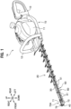
- the cutting work machine 1A of the first embodiment is a hand-held hedge trimmer used for trimming and pruning hedges and plants, as illustrated in FIG. 1 .
- the cutting work machine 1A includes a main unit 10 and a cutter unit 20 that is driven by the driving power of the main unit 10.
- the main unit 10 includes a main body case 11 made of resin, and a drive source such as an internal combustion engine or an electric motor (not shown) is housed inside the main body case 11.
- a drive source such as an internal combustion engine or an electric motor (not shown) is housed inside the main body case 11.
- a front handle 12 Provided in front of the main body case 11 is a front handle 12, and provided at rear of the main body case 11 is a rear handle 13.
- the operator uses the cutting work machine 1A, they grasp the front handle 12 and the rear handle 13, and operates the control unit such as the power switch or trigger lever provided on the rear handle 13.
- the cutter unit 20 includes an upper cutter support 30 that extends in a straight line forward from the main body case 11, and a lower cutter support 40 (see FIG. 3 ) that is connected to the upper cutter support 30.
- the cutter unit 20 also includes upper and lower blades 50, 60, which are connected to the upper cutter support 30 and the lower cutter support 40 in a freely movable manner in the front-back direction, and a guard member 70A that is provided at the front end portion of the upper cutter support 30.
- the upper cutter support 30 is a straight metallic member extending in the front-back direction, and the rear end portion thereof is connected to and fixed to the gear case (not shown) housed in the main body case 11.
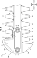
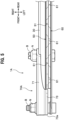
- the lower cutter support 40 is a straight metallic member extending in the front-back direction, as illustrated in FIG. 3 , and is positioned directly below the upper cutter support 30.
- a bolt B inserted from below into the mounting hole of the lower cutter support 40 is inserted into the mounting hole of the upper cutter support 30, and a nut N is screwed onto the tip portion of the bolt B.
- the lower cutter support 40 is connected to the lower surface of the upper cutter support 30 with a space between them in the up-down direction.
- the upper and lower blades 50, 60 are metallic cutting tools that extend in a straight line in the front-back direction.
- the upper and lower blades 50, 60 are stacked on top of each other above and below, and are positioned between the upper cutter support 30 and the lower cutter support 40, as shown in FIG. 5 .
- the upper cutter support 30 is located above both blades 50 and 60
- the lower cutter support 40 is located below both blades 50 and 60.
- a plurality of cutting edges 51 projecting on both the right and left sides are formed on the right and left sides, as shown in FIG. 3 .
- the cutting edges 51 on the right and left are arranged alternately from each other in the front-back direction.
- a plurality of cutting edges 61 projecting on both the right and left sides of the lower blade 60 are formed on the right and left sides of the lower blade 60 in the same manner as the upper blade 50.
- the upper and lower blades 50, 60 have a plurality of long holes 52, 62 extending in the front-back direction.
- Bolts B inserted into the mounting holes of the upper cutter support 30 and the lower cutter support 40 are inserted into the long holes 52, 62, which are connected in the upper and lower directions.
- the rear end portions of the upper and lower blades 50, 60 are inserted into the main body case 11 and connected to the gear case (not shown) in the main body case 11, as illustrated in FIG. 1 .
- the upper and lower blades 50, 60 are configured to reciprocate in opposite front-back directions by the driving power of the main unit 10, and cut branches by trapping them between the cutting edge 51 of the upper blade 50 and the cutting edge 61 of the lower blade 60.
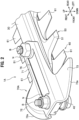
- the guard member 70A is provided at the front end portion of the upper cutter support 30, as shown in FIG. 2 .
- the guard member 70A is a metallic member to prevent the front end portions of the upper and lower blades 50, 60 from hitting a structure such as a wall or a building during trimming work by the cutting work machine 1A.
- the guard member 70A is fixed to the upper cutter support 30 above both blades 50, 60.
- the guard member 70A has a mounting portion 71 attached to the front end portion of the upper cutter support 30, a guard plate 72 projecting to the right from the mounting portion 71, and a fixed blade 73 projecting to the left from the mounting portion 71.
- the mounting portion 71 is a part that is overlaid on the upper surface of the front end portion of the upper cutter support 30. As illustrated in FIG. 3 , the mounting portion 71 is fixed to the upper surface of the upper cutter support 30 by inserting the bolts B, inserted into the mounting holes of the upper cutter support 30 and the lower cutter support 40, into the front and rear mounting holes 75, 75 formed in the mounting portion 71, and screwing nuts N onto the bolts B on the upper surface side of the mounting portion 71 (see FIG. 2 ). The front edge portion of the mounting portion 71 is positioned forward of the front end portions of both blades 50 and 60.
- the guard member 70A is made lighter in weight by forming an opening 76 between the front and rear mounting holes 75, 75.
- the guard plate 72 is a plate-shaped part projecting to the right from the front portion of the mounting portion 71, as illustrated in FIG. 4 .
- the right end portion of the guard plate 72 is located to the right of the right end portions of the right-side cutting edges 51, 61.
- the guard plate 72 is formed in a substantially triangular shape in a plan view.
- the front edge portion 72a of the guard plate 72 is inclined so as to be displaced backward as going to the right (outward in the right-left direction).
- the front edge portion 72a of the guard plate 72 is curved in an arc shape so as to be convex outwardly.
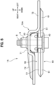
- the front edge portion 72a and the rear edge of the guard plate 72 are formed at a lower height than the position of the mounting portion 71 (upper surface of the upper cutter support 30), as illustrated in FIG. 6 .
- the guard plate 72 is depressed at the inner part than the front edge portion 72a and the rear edge portion when viewed from below.
- the guard plate 72 is positioned above the cutting edge 51 of the upper blade 50, as illustrated in FIG. 6 .
- the guard plate 72 is placed at a predetermined space to the upper surface of the cutting edge 51 so as not to touch the cutting edge 51 of the upper blade 50.
- the distance between the uppermost surface of the cutting edge 51 of the upper blade 50 and the lowermost surface of the guard plate 72 is set at about 3 mm to prevent branches and leaves from being trapped between the cutting edge 51 and the guard plate 72.
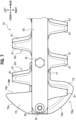
- the guard plate 72 is configured to cover the right foremost cutting edges 51, 61 of the upper and lower blades 50, 60 as illustrated in FIGs. 7 and 8 .
- the front edge portion 72a of the guard plate 72 is positioned forward of the foremost cutting edges 51, 61 of both blades 50, 60.
- the fixed blade 73 is a plate-shaped part projecting to the left from the front portion of the mounting portion 71, as illustrated in FIG. 4 .
- the left end portion of the fixed blade 73 is positioned to the left of the left end portion of the left-side cutting edge 61.
- the fixed blade 73 is formed in a substantially triangular shape in a plan view.
- the rear edge portion 73b of the fixed blade 73 extends in a straight line in the right-left direction orthogonal to the axial direction of the upper cutter support 30.
- the front edge portion 73a of the fixed blade 73 is inclined so as to be displaced backward as going to the left (outward in the right-left direction).
- the front edge portion 73a of the fixed blade 73 is curved in an arc shape so as to be convex outwardly.
- the operator holds the main unit 10 and swings the upper and lower blades 50, 60 in the right-left direction.
- the tip portions of the upper and lower blades 50, 60 move in an arc in the right-left direction.
- the front edge portion 72a of the guard plate 72 and the front edge portion 73a of the fixed blade 73 are curved in an arc shape convex outwardly.
- the fixed blade 73 faces forward against the foremost cutting edge 51 of the upper blade 50, as illustrated in FIG. 5 .
- the front edge portion 73a of the fixed blade 73 is positioned forward of the left foremost cutting edges 51 and 61 of both lower blades 50 and 60.
- the rear edge portion of the guard plate 72 is positioned rearward of the rear edge portion 73b of the fixed blade 73.
- the position in the up-down direction of the lower surface of the fixed blade 73 and the position in the up-down direction of the lower surface of the cutting edge 51 of the upper blade 50 are located at approximately the same position. Note that the position in the up-down direction of the lower surface of the fixed blade 73 is preferably set at or below the position in the up-down direction of the upper surface of the cutting edge 51 of the upper blade 50.
- the fixed blade 73 and the left foremost cutting edge 61 of the lower blade 60 are separated in the front-back direction.
- the fixed blade 73 is configured not to overlap the cutting edge 61 of the lower blade 60 when the lower blade 60 is most retracted. Also, the fixed blade 73 and the left foremost cutting edge 51 of the upper blade 50 are separated in the front-back direction.
- the upper surface of the left foremost cutting edge 61 of the lower blade 60 is configured to overlap the lower surface of the fixed blade 73.
- the fixed blade 73 is configured to overlap at least a portion of the cutting edge 61 of the lower blade 60 when the lower blade 60 is most advanced. This makes it possible to trap branches at their front and back and cut them by the fixed blade 73 and the lower cutting edge 61.
- the clearance is configured to be about 15 mm. This allows extending the area that can be trimmed by the fixed blade 73 and the lower cutting edge 61 at the tip portion of the cutting work machine 1A.
- the cutting work machine 1A of the first embodiment includes a main unit 10 and a cutter unit 20 that is driven by the driving power of the main unit 10.
- the cutter unit 20 includes an upper cutter support 30 that extends forward from the main unit 10, upper and lower blades 50, 60, which are connected to the upper cutter support 30 in a freely movable manner in the front-back direction, and a guard member 70A that is provided at the front end portion of the upper cutter support 30.
- Both blades 50 and 60 include cutting edges 51 and 61 projecting in the right-left direction. Both blades 50 and 60, stacked on top of each other above and below, are configured to reciprocate in opposite front-back directions.
- the guard member 70A includes a guard plate 72 that projects to the right from the upper cutter support 30 and a fixed blade 73 that projects to the left from the upper cutter support 30.
- the front edge portions 72a, 73a of the guard plate 72 and the fixed blade 73 are positioned forward of the foremost cutting edges 51, 61 of both blades 50, 60.
- the guard plate 72 is positioned above the cutting edge 51 of the upper blade 50.
- the fixed blade 73 faces forward against the foremost cutting edge 51 of the upper blade 50.
- the cutting work machine 1A of the first embodiment is configured so that the fixed blade 73 does not overlap the cutting edge 61 of the lower blade 60 when the lower blade 60 is most retracted.
- the fixed blade 73 is configured to overlap at least a portion of the cutting edge 61 of the lower blade 60 when the lower blade 60 is most advanced, as illustrated in FIG. 8 .
- the guard plate 72 and the fixed blade 73 of the guard member 70A can prevent the front end portions of both blades 50, 60 from hitting a structure, thereby protecting both blades 50, 60.
- the guard plate 72 of the guard member 70A covers the cutting edges 51, 61 at the front portions of both blades 50, 60, making it possible to prevent branches from being chewed between the upper and lower cutting edges 51, 61.
- branches in the vicinity of a structure can be easily cut because branches can be trapped and cut by the fixed blade 73 of the guard member 70A provided at the front end portion of the upper cutter support 30 and the foremost cutting edge 61 of the lower blade 60. Therefore, the cutting work machine 1A of the first embodiment can increase the work efficiency of trimming and pruning hedges and plants.
- the front edge portions 72a, 73a of the guard plate 72 and the fixed blade 73 are inclined so as to be displaced backward as going outward in the right-left direction.
- branches in front of the guard member 70A can be easily guided along the front edge portions 72a, 73a of the guard plate 72 and the fixed blade 73 to the rear of the guard member 70A, so that the branches in the vicinity of the structure can be easily cut.
- the position in the up-down direction of the lower surface of the fixed blade 73 is at or below the position in the up-down direction of the upper surface of the cutting edge 51 of the upper blade 50.
- the rear edge portion of the guard plate 72 is positioned rearward of the rear edge portion of the fixed blade 73, as illustrated in FIG. 4 . With this configuration, it is difficult for chewing to occur behind the guard plate 72.
- the cutting work machine is not limited to the first embodiment.
- the guard plate 72 projects to the right from the upper cutter support 30 and the fixed blade 73 projects to the left from the upper cutter support 30.
- the guard plate 72 may be allowed to project to the left from the upper cutter support 30 and the fixed blade 73 may be allowed to project to the right from the upper cutter support 30.
- the guard plate 72 and the fixed blade 73 are formed in a substantially triangular shape in a plan view, but the shapes of the guard plate 72 and the fixed blade 73 are not limited and may, for example, be extended in a straight line in the right-left direction.
- the rear end surface of the fixed blade 73 of the first embodiment is formed perpendicular to the upper surface and lower surface, but may be inclined from the upper surface and lower surface to enhance the cutting performance of the fixed blade 73.
- the upper cutter support 30 and the guard member 70A are separately formed, but the guard member 70A may be integrally formed at the front end portion of the upper cutter support 30.
- the cutting work machine 1B of the second embodiment has substantially the same configuration as that of the cutting work machine 1A of the first embodiment (see FIG. 6 ), with the difference being the arrangement of the guard member 70B.
- the guard member 70B of the second embodiment is provided at the front end portion of the lower cutter support 40.
- the guard member 70B of the second embodiment is connected to the upper cutter support 30 via the lower cutter support 40.
- the guard plate 72 of the guard member 70B is positioned below the cutting edge 61 of the lower blade 60.
- the fixed blade 73 of the second embodiment faces forward against the foremost cutting edge 61 of the lower blade 60.
- the fixed blade 73 is configured not to overlap the cutting edge 51 of the upper blade 50 when the upper blade 50 is most retracted. Also, the fixed blade 73 is configured to overlap at least a portion of the cutting edge 51 of the upper blade 50 when the upper blade 50 is most advanced. This makes it possible to trap branches at their front and back and cut them by the fixed blade 73 and the foremost cutting edge 51 of the upper blade 50.
- the guard member 70B is integrally formed on the lower cutter support 40, but the lower cutter support 40 and the guard member 70B may be formed separately.
Landscapes
- Life Sciences & Earth Sciences (AREA)
- Biodiversity & Conservation Biology (AREA)
- Ecology (AREA)
- Forests & Forestry (AREA)
- Environmental Sciences (AREA)
- Harvester Elements (AREA)
Claims (9)
- Schneidende Arbeitsmaschine mit:einer Haupteinheit; undeiner Messereinheit, die durch die Antriebsleistung der Haupteinheit angetrieben wird, wobeidie Messereinheit Folgendes umfassteine sich von der Haupteinheit nach vorne erstreckende Messerhalterung,Ober- und Untermesser, die mit der Messerhalterung in einer Vorwärts-Rückwärts-Richtung frei beweglich verbunden sind, undein an einem vorderen Endabschnitt der Messerhalterung vorgesehenes Schutzelement,wobei beide Messer Schneidkanten haben, die in einer Rechts-Links-Richtung vorstehen,wobei die beiden oben und unten übereinander gestapelten Messer so gestaltet sind, dass sie sich in entgegengesetzten Vorwärts-Rückwärts-Richtungen hin- und herbewegen,wobei das Schutzelement Folgendes umfasst
eine Schutzplatte, die in eine von Rechts- und Links-Richtungen von der Messerhalterung vorsteht, undein vorderer Kantenabschnitt der Schutzplatte vor den vordersten Schneidkanten der beiden Messer angeordnet ist,wobei sich die Schutzplatte über der Schneidkante des Obermessers befindet,dadurch gekennzeichnet, dass die Schutzplatte außerdem Folgendes umfasstein feststehendes Messer, das in die andere der Rechts- und Links-Richtungen von der Messerhalterung vorsteht, und dessen vorderer Kantenabschnitt vor den vordersten Schneidkanten der beiden Messer angeordnet ist,wobei das feststehende Messer nach vorne gegen die vorderste Kante des oberen Messers gerichtet ist. - Schneidende Arbeitsmaschine nach Anspruch 1, wobei
eine Position in einer Aufwärts-Abwärts-Richtung einer unteren Fläche des feststehenden Messers an oder unter einer Position in der Aufwärts-Abwärts-Richtung einer oberen Fläche der Schneidkante des oberen Messers liegt. - Schneidende Arbeitsmaschine nach Anspruch 1, wobeidas feststehende Messer so gestaltet ist, dass es die Schneidkante des unteren Messers nicht überlappt, wenn das untere Messer am weitesten zurückgezogen ist, unddas feststehende Messer so gestaltet ist, dass es mindestens einen Teil der Schneidkante des unteren Messers überlappt, wenn das untere Messer am weitesten vorgeschoben ist.
- Schneidende Arbeitsmaschine mit:einer Haupteinheit; undeiner Messereinheit, die durch die Antriebsleistung der Haupteinheit angetrieben wird, wobeidie Messereinheit Folgendes umfassteine sich von der Haupteinheit nach vorne erstreckende Messerhalterung,Ober- und Untermesser, die mit der Messerhalterung in einer Vorwärts-Rückwärts-Richtung frei beweglich verbunden sind, undein an einem vorderen Endabschnitt der Messerhalterung vorgesehenes Schutzelement,wobei beide Messer Schneidkanten haben, die in einer Rechts-Links-Richtung vorstehen,wobei die beiden oben und unten übereinander gestapelten Messer so gestaltet sind, dass sie sich in entgegengesetzten Vorwärts-Rückwärts-Richtungen hin- und herbewegen,wobei das Schutzelement Folgendes umfasst
eine Schutzplatte, die in eine von Rechts- und Links-Richtungen von der Messerhalterung vorsteht, undein vorderer Kantenabschnitt der Schutzplatte vor den vordersten Schneidkanten der beiden Messer angeordnet ist,wobei sich die Schutzplatte unter der Schneidkante des Obermessers befindet,dadurch gekennzeichnet, dass die Schutzplatte außerdem Folgendes umfasstein feststehendes Messer, das in die andere der Rechts- und Links-Richtungen von der Messerhalterung vorsteht, und dessen vorderer Kantenabschnitt vor den vordersten Schneidkanten der beiden Messer angeordnet ist,wobei das feststehende Messer nach vorne gegen die vorderste Kante des unteren Messers gerichtet ist. - Schneidende Arbeitsmaschine nach Anspruch 4, wobeidas feststehende Messer so gestaltet ist, dass es die Schneidkante des oberen Messers nicht überlappt, wenn das obere Messer am weitesten zurückgezogen ist, unddas feststehende Messer so gestaltet ist, dass es mindestens einen Teil der Schneidkante des oberen Messers überlappt, wenn das obere Messer am weitesten vorgeschoben ist.
- Schneidende Arbeitsmaschine nach Anspruch 1, wobei
die Vorderkantenabschnitte der Schutzplatte und des feststehenden Messers so geneigt sind, dass sie in der Rechts-Links-Richtung nach hinten verschoben werden. - Schneidende Arbeitsmaschine nach Anspruch 4, wobei
die Vorderkantenabschnitte der Schutzplatte und des feststehenden Messers so geneigt sind, dass sie in der Rechts-Links-Richtung nach hinten verschoben werden. - Schneidende Arbeitsmaschine nach Anspruch 1, wobei
ein Hinterkantenabschnitt der Schutzplatte hinter einem Hinterkantenabschnitt des feststehenden Messers angeordnet ist. - Schneidende Arbeitsmaschine nach Anspruch 4, wobei
ein Hinterkantenabschnitt der Schutzplatte hinter einem Hinterkantenabschnitt des feststehenden Messers angeordnet ist.
Applications Claiming Priority (1)
| Application Number | Priority Date | Filing Date | Title |
|---|---|---|---|
| JP2020208726A JP7489305B2 (ja) | 2020-12-16 | 2020-12-16 | 切断作業機 |
Publications (2)
| Publication Number | Publication Date |
|---|---|
| EP4014716A1 EP4014716A1 (de) | 2022-06-22 |
| EP4014716B1 true EP4014716B1 (de) | 2023-06-14 |
Family
ID=79024093
Family Applications (1)
| Application Number | Title | Priority Date | Filing Date |
|---|---|---|---|
| EP21215068.4A Active EP4014716B1 (de) | 2020-12-16 | 2021-12-16 | Schneidende arbeitsmaschine |
Country Status (3)
| Country | Link |
|---|---|
| US (1) | US11839185B2 (de) |
| EP (1) | EP4014716B1 (de) |
| JP (1) | JP7489305B2 (de) |
Families Citing this family (2)
| Publication number | Priority date | Publication date | Assignee | Title |
|---|---|---|---|---|
| JP2024129585A (ja) * | 2023-03-13 | 2024-09-27 | 株式会社やまびこ | カッター組立体及びヘッジトリマー |
| DE102023202455A1 (de) * | 2023-03-20 | 2024-09-26 | Robert Bosch Gesellschaft mit beschränkter Haftung | Messeranordnung für ein Gartengerät |
Family Cites Families (26)
| Publication number | Priority date | Publication date | Assignee | Title |
|---|---|---|---|---|
| US68109A (en) * | 1867-08-27 | Improvement in pruning-knife, hook, and saw | ||
| US1693707A (en) * | 1927-08-11 | 1928-12-04 | Dishmaker Anton | Clipper |
| US2664626A (en) * | 1948-02-16 | 1954-01-05 | Sunbeam Corp | Hedge trimmer |
| US2564032A (en) * | 1948-07-20 | 1951-08-14 | King Pneumatic Tool Company | Hedge trimming device |
| US3309769A (en) * | 1965-03-22 | 1967-03-21 | Vermont American Corp | Hedge trimmer having a reciprocating saw |
| US3364574A (en) * | 1966-08-18 | 1968-01-23 | Rockwell Mfg Co | Wood cutting saw blade attachment for hedge trimmer |
| US3564714A (en) * | 1968-04-19 | 1971-02-23 | Black & Decker Mfg Co | Trimmer blade tooth configuration |
| US3552013A (en) * | 1968-05-21 | 1971-01-05 | William C Stone | Hedge clipper attachment |
| US3795050A (en) * | 1972-10-11 | 1974-03-05 | A Latsha | Trimmer catch box |
| JPS5839074Y2 (ja) * | 1978-10-31 | 1983-09-03 | 松下電工株式会社 | 庭木バリカンの刈込刃 |
| US4280276A (en) * | 1980-01-18 | 1981-07-28 | The Toro Company | Reciprocating cutter |
| DE3231899C2 (de) * | 1982-08-27 | 1986-07-17 | Metabowerke GmbH & Co, 7440 Nürtingen | Schutzvorrichtung für Heckenscheren |
| JPH0538574Y2 (de) * | 1989-01-30 | 1993-09-29 | ||
| US5048277A (en) * | 1990-08-02 | 1991-09-17 | Joseph Trimarco | Hedge trimmer |
| US5653029A (en) * | 1996-02-05 | 1997-08-05 | Shigenaka; Bob | Hedge trimmer debris guide |
| DE29721822U1 (de) * | 1997-12-10 | 1998-02-19 | FREUND VICTORIA Gartengeräte GmbH, 73614 Schorndorf | Heckenschere mit elektromotorischem Antrieb |
| FR2939008B1 (fr) * | 2008-12-01 | 2011-06-24 | Pellenc Sa | Appareil de taille motorise auto-decoincant, en particulier taille-haie |
| JP2011036185A (ja) | 2009-08-12 | 2011-02-24 | Genpei Hamono Kojo:Kk | バリカン式刈刃装置 |
| JP2015104362A (ja) | 2013-11-29 | 2015-06-08 | 日立工機株式会社 | ヘッジトリマ |
| JP2015116131A (ja) | 2013-12-17 | 2015-06-25 | 日立工機株式会社 | 刈込機 |
| JP6484807B2 (ja) * | 2015-06-10 | 2019-03-20 | 株式会社やまびこ | 往復動作業機 |
| JP2019193598A (ja) * | 2018-05-02 | 2019-11-07 | 株式会社やまびこ | ヘッジトリマー |
| CN209628154U (zh) * | 2019-01-23 | 2019-11-15 | 余姚市林鼎传动有限公司 | 一种修枝机刀片组件结构 |
| JP7175843B2 (ja) * | 2019-05-27 | 2022-11-21 | 株式会社マキタ | 園芸用トリマ |
| JP7249228B2 (ja) * | 2019-07-18 | 2023-03-30 | 株式会社マキタ | 電動作業機 |
| JP2023068346A (ja) * | 2021-11-02 | 2023-05-17 | 株式会社マキタ | 一対のブレードを備える作業機および一対のブレード |
-
2020
- 2020-12-16 JP JP2020208726A patent/JP7489305B2/ja active Active
-
2021
- 2021-12-15 US US17/551,836 patent/US11839185B2/en active Active
- 2021-12-16 EP EP21215068.4A patent/EP4014716B1/de active Active
Also Published As
| Publication number | Publication date |
|---|---|
| US11839185B2 (en) | 2023-12-12 |
| JP7489305B2 (ja) | 2024-05-23 |
| EP4014716A1 (de) | 2022-06-22 |
| US20220183234A1 (en) | 2022-06-16 |
| JP2022095409A (ja) | 2022-06-28 |
Similar Documents
| Publication | Publication Date | Title |
|---|---|---|
| EP4014716B1 (de) | Schneidende arbeitsmaschine | |
| JP7734011B2 (ja) | 刈込機 | |
| JP7570219B2 (ja) | ヘッジトリマ | |
| CN112237105A (zh) | 电动作业机械 | |
| US9468143B2 (en) | Grass blade for a trimmer | |
| EP2681987A1 (de) | Elektrisch gesteuertes Gartenwerkzeug | |
| EP3189723B1 (de) | Vegetationsschneidevorrichtung mit sägeblatt | |
| JP7825516B2 (ja) | 切断工具 | |
| EP3509415B1 (de) | Verbesserter astschneider | |
| US20240306554A1 (en) | Cutter Assembly And Hedge Trimmer | |
| CN110115168B (zh) | 电动工具 | |
| CN101803540B (zh) | 修剪树篱用的一种剪刀的刀装置 | |
| JP2018014953A (ja) | ロングヘッジトリマ | |
| CN212677843U (zh) | 作业机械 | |
| EP4437834A1 (de) | Heckenschere | |
| US6722045B2 (en) | Guide bar having rotating guide discs | |
| JP4813267B2 (ja) | 電動刈り込み機 | |
| JP2014082939A (ja) | ヘッジトリマ | |
| EP3379917B1 (de) | Auffanganordnung für eine leistungsvorrichtung | |
| JP5252197B2 (ja) | チェーンソー | |
| BE1026096A9 (nl) | In de hand te houden werkmachine | |
| JP2021084168A (ja) | 作業機 | |
| WO2014022881A1 (en) | Cutting apparatus | |
| WO2017213567A1 (en) | A blade assembly for a cutting device and a cutting device |
Legal Events
| Date | Code | Title | Description |
|---|---|---|---|
| PUAI | Public reference made under article 153(3) epc to a published international application that has entered the european phase |
Free format text: ORIGINAL CODE: 0009012 |
|
| STAA | Information on the status of an ep patent application or granted ep patent |
Free format text: STATUS: THE APPLICATION HAS BEEN PUBLISHED |
|
| AK | Designated contracting states |
Kind code of ref document: A1 Designated state(s): AL AT BE BG CH CY CZ DE DK EE ES FI FR GB GR HR HU IE IS IT LI LT LU LV MC MK MT NL NO PL PT RO RS SE SI SK SM TR |
|
| STAA | Information on the status of an ep patent application or granted ep patent |
Free format text: STATUS: REQUEST FOR EXAMINATION WAS MADE |
|
| 17P | Request for examination filed |
Effective date: 20220803 |
|
| RBV | Designated contracting states (corrected) |
Designated state(s): AL AT BE BG CH CY CZ DE DK EE ES FI FR GB GR HR HU IE IS IT LI LT LU LV MC MK MT NL NO PL PT RO RS SE SI SK SM TR |
|
| RIC1 | Information provided on ipc code assigned before grant |
Ipc: A01G 3/053 20060101AFI20221121BHEP |
|
| GRAP | Despatch of communication of intention to grant a patent |
Free format text: ORIGINAL CODE: EPIDOSNIGR1 |
|
| STAA | Information on the status of an ep patent application or granted ep patent |
Free format text: STATUS: GRANT OF PATENT IS INTENDED |
|
| INTG | Intention to grant announced |
Effective date: 20230112 |
|
| GRAS | Grant fee paid |
Free format text: ORIGINAL CODE: EPIDOSNIGR3 |
|
| GRAA | (expected) grant |
Free format text: ORIGINAL CODE: 0009210 |
|
| STAA | Information on the status of an ep patent application or granted ep patent |
Free format text: STATUS: THE PATENT HAS BEEN GRANTED |
|
| AK | Designated contracting states |
Kind code of ref document: B1 Designated state(s): AL AT BE BG CH CY CZ DE DK EE ES FI FR GB GR HR HU IE IS IT LI LT LU LV MC MK MT NL NO PL PT RO RS SE SI SK SM TR |
|
| REG | Reference to a national code |
Ref country code: CH Ref legal event code: EP |
|
| REG | Reference to a national code |
Ref country code: DE Ref legal event code: R096 Ref document number: 602021002941 Country of ref document: DE |
|
| REG | Reference to a national code |
Ref country code: AT Ref legal event code: REF Ref document number: 1578529 Country of ref document: AT Kind code of ref document: T Effective date: 20230715 |
|
| REG | Reference to a national code |
Ref country code: SE Ref legal event code: TRGR |
|
| REG | Reference to a national code |
Ref country code: LT Ref legal event code: MG9D |
|
| REG | Reference to a national code |
Ref country code: NL Ref legal event code: MP Effective date: 20230614 |
|
| PG25 | Lapsed in a contracting state [announced via postgrant information from national office to epo] |
Ref country code: NO Free format text: LAPSE BECAUSE OF FAILURE TO SUBMIT A TRANSLATION OF THE DESCRIPTION OR TO PAY THE FEE WITHIN THE PRESCRIBED TIME-LIMIT Effective date: 20230914 Ref country code: ES Free format text: LAPSE BECAUSE OF FAILURE TO SUBMIT A TRANSLATION OF THE DESCRIPTION OR TO PAY THE FEE WITHIN THE PRESCRIBED TIME-LIMIT Effective date: 20230614 |
|
| REG | Reference to a national code |
Ref country code: AT Ref legal event code: MK05 Ref document number: 1578529 Country of ref document: AT Kind code of ref document: T Effective date: 20230614 |
|
| PG25 | Lapsed in a contracting state [announced via postgrant information from national office to epo] |
Ref country code: RS Free format text: LAPSE BECAUSE OF FAILURE TO SUBMIT A TRANSLATION OF THE DESCRIPTION OR TO PAY THE FEE WITHIN THE PRESCRIBED TIME-LIMIT Effective date: 20230614 Ref country code: NL Free format text: LAPSE BECAUSE OF FAILURE TO SUBMIT A TRANSLATION OF THE DESCRIPTION OR TO PAY THE FEE WITHIN THE PRESCRIBED TIME-LIMIT Effective date: 20230614 Ref country code: LV Free format text: LAPSE BECAUSE OF FAILURE TO SUBMIT A TRANSLATION OF THE DESCRIPTION OR TO PAY THE FEE WITHIN THE PRESCRIBED TIME-LIMIT Effective date: 20230614 Ref country code: LT Free format text: LAPSE BECAUSE OF FAILURE TO SUBMIT A TRANSLATION OF THE DESCRIPTION OR TO PAY THE FEE WITHIN THE PRESCRIBED TIME-LIMIT Effective date: 20230614 Ref country code: HR Free format text: LAPSE BECAUSE OF FAILURE TO SUBMIT A TRANSLATION OF THE DESCRIPTION OR TO PAY THE FEE WITHIN THE PRESCRIBED TIME-LIMIT Effective date: 20230614 Ref country code: GR Free format text: LAPSE BECAUSE OF FAILURE TO SUBMIT A TRANSLATION OF THE DESCRIPTION OR TO PAY THE FEE WITHIN THE PRESCRIBED TIME-LIMIT Effective date: 20230915 |
|
| PG25 | Lapsed in a contracting state [announced via postgrant information from national office to epo] |
Ref country code: FI Free format text: LAPSE BECAUSE OF FAILURE TO SUBMIT A TRANSLATION OF THE DESCRIPTION OR TO PAY THE FEE WITHIN THE PRESCRIBED TIME-LIMIT Effective date: 20230614 |
|
| PG25 | Lapsed in a contracting state [announced via postgrant information from national office to epo] |
Ref country code: SK Free format text: LAPSE BECAUSE OF FAILURE TO SUBMIT A TRANSLATION OF THE DESCRIPTION OR TO PAY THE FEE WITHIN THE PRESCRIBED TIME-LIMIT Effective date: 20230614 |
|
| PG25 | Lapsed in a contracting state [announced via postgrant information from national office to epo] |
Ref country code: IS Free format text: LAPSE BECAUSE OF FAILURE TO SUBMIT A TRANSLATION OF THE DESCRIPTION OR TO PAY THE FEE WITHIN THE PRESCRIBED TIME-LIMIT Effective date: 20231014 |
|
| PG25 | Lapsed in a contracting state [announced via postgrant information from national office to epo] |
Ref country code: SM Free format text: LAPSE BECAUSE OF FAILURE TO SUBMIT A TRANSLATION OF THE DESCRIPTION OR TO PAY THE FEE WITHIN THE PRESCRIBED TIME-LIMIT Effective date: 20230614 Ref country code: SK Free format text: LAPSE BECAUSE OF FAILURE TO SUBMIT A TRANSLATION OF THE DESCRIPTION OR TO PAY THE FEE WITHIN THE PRESCRIBED TIME-LIMIT Effective date: 20230614 Ref country code: RO Free format text: LAPSE BECAUSE OF FAILURE TO SUBMIT A TRANSLATION OF THE DESCRIPTION OR TO PAY THE FEE WITHIN THE PRESCRIBED TIME-LIMIT Effective date: 20230614 Ref country code: PT Free format text: LAPSE BECAUSE OF FAILURE TO SUBMIT A TRANSLATION OF THE DESCRIPTION OR TO PAY THE FEE WITHIN THE PRESCRIBED TIME-LIMIT Effective date: 20231016 Ref country code: IS Free format text: LAPSE BECAUSE OF FAILURE TO SUBMIT A TRANSLATION OF THE DESCRIPTION OR TO PAY THE FEE WITHIN THE PRESCRIBED TIME-LIMIT Effective date: 20231014 Ref country code: EE Free format text: LAPSE BECAUSE OF FAILURE TO SUBMIT A TRANSLATION OF THE DESCRIPTION OR TO PAY THE FEE WITHIN THE PRESCRIBED TIME-LIMIT Effective date: 20230614 Ref country code: CZ Free format text: LAPSE BECAUSE OF FAILURE TO SUBMIT A TRANSLATION OF THE DESCRIPTION OR TO PAY THE FEE WITHIN THE PRESCRIBED TIME-LIMIT Effective date: 20230614 Ref country code: AT Free format text: LAPSE BECAUSE OF FAILURE TO SUBMIT A TRANSLATION OF THE DESCRIPTION OR TO PAY THE FEE WITHIN THE PRESCRIBED TIME-LIMIT Effective date: 20230614 |
|
| PG25 | Lapsed in a contracting state [announced via postgrant information from national office to epo] |
Ref country code: PL Free format text: LAPSE BECAUSE OF FAILURE TO SUBMIT A TRANSLATION OF THE DESCRIPTION OR TO PAY THE FEE WITHIN THE PRESCRIBED TIME-LIMIT Effective date: 20230614 |
|
| REG | Reference to a national code |
Ref country code: DE Ref legal event code: R097 Ref document number: 602021002941 Country of ref document: DE |
|
| PLBE | No opposition filed within time limit |
Free format text: ORIGINAL CODE: 0009261 |
|
| STAA | Information on the status of an ep patent application or granted ep patent |
Free format text: STATUS: NO OPPOSITION FILED WITHIN TIME LIMIT |
|
| PG25 | Lapsed in a contracting state [announced via postgrant information from national office to epo] |
Ref country code: DK Free format text: LAPSE BECAUSE OF FAILURE TO SUBMIT A TRANSLATION OF THE DESCRIPTION OR TO PAY THE FEE WITHIN THE PRESCRIBED TIME-LIMIT Effective date: 20230614 |
|
| PG25 | Lapsed in a contracting state [announced via postgrant information from national office to epo] |
Ref country code: SI Free format text: LAPSE BECAUSE OF FAILURE TO SUBMIT A TRANSLATION OF THE DESCRIPTION OR TO PAY THE FEE WITHIN THE PRESCRIBED TIME-LIMIT Effective date: 20230614 |
|
| 26N | No opposition filed |
Effective date: 20240315 |
|
| PG25 | Lapsed in a contracting state [announced via postgrant information from national office to epo] |
Ref country code: SI Free format text: LAPSE BECAUSE OF FAILURE TO SUBMIT A TRANSLATION OF THE DESCRIPTION OR TO PAY THE FEE WITHIN THE PRESCRIBED TIME-LIMIT Effective date: 20230614 Ref country code: IT Free format text: LAPSE BECAUSE OF FAILURE TO SUBMIT A TRANSLATION OF THE DESCRIPTION OR TO PAY THE FEE WITHIN THE PRESCRIBED TIME-LIMIT Effective date: 20230614 |
|
| PG25 | Lapsed in a contracting state [announced via postgrant information from national office to epo] |
Ref country code: LU Free format text: LAPSE BECAUSE OF NON-PAYMENT OF DUE FEES Effective date: 20231216 |
|
| PG25 | Lapsed in a contracting state [announced via postgrant information from national office to epo] |
Ref country code: MC Free format text: LAPSE BECAUSE OF FAILURE TO SUBMIT A TRANSLATION OF THE DESCRIPTION OR TO PAY THE FEE WITHIN THE PRESCRIBED TIME-LIMIT Effective date: 20230614 |
|
| REG | Reference to a national code |
Ref country code: BE Ref legal event code: MM Effective date: 20231231 |
|
| PG25 | Lapsed in a contracting state [announced via postgrant information from national office to epo] |
Ref country code: MC Free format text: LAPSE BECAUSE OF FAILURE TO SUBMIT A TRANSLATION OF THE DESCRIPTION OR TO PAY THE FEE WITHIN THE PRESCRIBED TIME-LIMIT Effective date: 20230614 Ref country code: LU Free format text: LAPSE BECAUSE OF NON-PAYMENT OF DUE FEES Effective date: 20231216 |
|
| REG | Reference to a national code |
Ref country code: IE Ref legal event code: MM4A |
|
| PG25 | Lapsed in a contracting state [announced via postgrant information from national office to epo] |
Ref country code: IE Free format text: LAPSE BECAUSE OF NON-PAYMENT OF DUE FEES Effective date: 20231216 |
|
| PG25 | Lapsed in a contracting state [announced via postgrant information from national office to epo] |
Ref country code: BE Free format text: LAPSE BECAUSE OF NON-PAYMENT OF DUE FEES Effective date: 20231231 |
|
| PG25 | Lapsed in a contracting state [announced via postgrant information from national office to epo] |
Ref country code: IE Free format text: LAPSE BECAUSE OF NON-PAYMENT OF DUE FEES Effective date: 20231216 Ref country code: BE Free format text: LAPSE BECAUSE OF NON-PAYMENT OF DUE FEES Effective date: 20231231 |
|
| PG25 | Lapsed in a contracting state [announced via postgrant information from national office to epo] |
Ref country code: BG Free format text: LAPSE BECAUSE OF FAILURE TO SUBMIT A TRANSLATION OF THE DESCRIPTION OR TO PAY THE FEE WITHIN THE PRESCRIBED TIME-LIMIT Effective date: 20230614 |
|
| PG25 | Lapsed in a contracting state [announced via postgrant information from national office to epo] |
Ref country code: BG Free format text: LAPSE BECAUSE OF FAILURE TO SUBMIT A TRANSLATION OF THE DESCRIPTION OR TO PAY THE FEE WITHIN THE PRESCRIBED TIME-LIMIT Effective date: 20230614 |
|
| PG25 | Lapsed in a contracting state [announced via postgrant information from national office to epo] |
Ref country code: CY Free format text: LAPSE BECAUSE OF FAILURE TO SUBMIT A TRANSLATION OF THE DESCRIPTION OR TO PAY THE FEE WITHIN THE PRESCRIBED TIME-LIMIT; INVALID AB INITIO Effective date: 20211216 |
|
| REG | Reference to a national code |
Ref country code: CH Ref legal event code: PL |
|
| PG25 | Lapsed in a contracting state [announced via postgrant information from national office to epo] |
Ref country code: CH Free format text: LAPSE BECAUSE OF NON-PAYMENT OF DUE FEES Effective date: 20241231 |
|
| PG25 | Lapsed in a contracting state [announced via postgrant information from national office to epo] |
Ref country code: TR Free format text: LAPSE BECAUSE OF FAILURE TO SUBMIT A TRANSLATION OF THE DESCRIPTION OR TO PAY THE FEE WITHIN THE PRESCRIBED TIME-LIMIT Effective date: 20230614 |
|
| PGFP | Annual fee paid to national office [announced via postgrant information from national office to epo] |
Ref country code: DE Payment date: 20251211 Year of fee payment: 5 |
|
| PGFP | Annual fee paid to national office [announced via postgrant information from national office to epo] |
Ref country code: GB Payment date: 20251219 Year of fee payment: 5 |
|
| PGFP | Annual fee paid to national office [announced via postgrant information from national office to epo] |
Ref country code: FR Payment date: 20251229 Year of fee payment: 5 |
|
| PGFP | Annual fee paid to national office [announced via postgrant information from national office to epo] |
Ref country code: SE Payment date: 20251219 Year of fee payment: 5 |