EP4012471B1 - Imaging optical system and imaging device - Google Patents
Imaging optical system and imaging device Download PDFInfo
- Publication number
- EP4012471B1 EP4012471B1 EP20868379.7A EP20868379A EP4012471B1 EP 4012471 B1 EP4012471 B1 EP 4012471B1 EP 20868379 A EP20868379 A EP 20868379A EP 4012471 B1 EP4012471 B1 EP 4012471B1
- Authority
- EP
- European Patent Office
- Prior art keywords
- optical system
- imaging
- image
- imaging optical
- aperture stop
- Prior art date
- Legal status (The legal status is an assumption and is not a legal conclusion. Google has not performed a legal analysis and makes no representation as to the accuracy of the status listed.)
- Active
Links
Images








Classifications
-
- G—PHYSICS
- G02—OPTICS
- G02B—OPTICAL ELEMENTS, SYSTEMS OR APPARATUS
- G02B23/00—Telescopes, e.g. binoculars; Periscopes; Instruments for viewing the inside of hollow bodies; Viewfinders; Optical aiming or sighting devices
- G02B23/24—Instruments or systems for viewing the inside of hollow bodies, e.g. fibrescopes
- G02B23/2407—Optical details
- G02B23/2423—Optical details of the distal end
-
- G—PHYSICS
- G02—OPTICS
- G02B—OPTICAL ELEMENTS, SYSTEMS OR APPARATUS
- G02B13/00—Optical objectives specially designed for the purposes specified below
- G02B13/02—Telephoto objectives, i.e. systems of the type + - in which the distance from the front vertex to the image plane is less than the equivalent focal length
-
- G—PHYSICS
- G02—OPTICS
- G02B—OPTICAL ELEMENTS, SYSTEMS OR APPARATUS
- G02B5/00—Optical elements other than lenses
- G02B5/30—Polarising elements
- G02B5/3083—Birefringent or phase retarding elements
-
- G—PHYSICS
- G02—OPTICS
- G02B—OPTICAL ELEMENTS, SYSTEMS OR APPARATUS
- G02B21/00—Microscopes
- G02B21/0004—Microscopes specially adapted for specific applications
- G02B21/0012—Surgical microscopes
-
- G—PHYSICS
- G02—OPTICS
- G02B—OPTICAL ELEMENTS, SYSTEMS OR APPARATUS
- G02B21/00—Microscopes
- G02B21/18—Arrangements with more than one light path, e.g. for comparing two specimens
- G02B21/20—Binocular arrangements
- G02B21/22—Stereoscopic arrangements
-
- G—PHYSICS
- G02—OPTICS
- G02B—OPTICAL ELEMENTS, SYSTEMS OR APPARATUS
- G02B21/00—Microscopes
- G02B21/36—Microscopes arranged for photographic purposes or projection purposes or digital imaging or video purposes including associated control and data processing arrangements
- G02B21/361—Optical details, e.g. image relay to the camera or image sensor
-
- G—PHYSICS
- G02—OPTICS
- G02B—OPTICAL ELEMENTS, SYSTEMS OR APPARATUS
- G02B23/00—Telescopes, e.g. binoculars; Periscopes; Instruments for viewing the inside of hollow bodies; Viewfinders; Optical aiming or sighting devices
- G02B23/24—Instruments or systems for viewing the inside of hollow bodies, e.g. fibrescopes
- G02B23/26—Instruments or systems for viewing the inside of hollow bodies, e.g. fibrescopes using light guides
-
- G—PHYSICS
- G02—OPTICS
- G02B—OPTICAL ELEMENTS, SYSTEMS OR APPARATUS
- G02B27/00—Optical systems or apparatus not provided for by any of the groups G02B1/00 - G02B26/00, G02B30/00
- G02B27/0075—Optical systems or apparatus not provided for by any of the groups G02B1/00 - G02B26/00, G02B30/00 with means for altering, e.g. increasing, the depth of field or depth of focus
-
- G—PHYSICS
- G02—OPTICS
- G02B—OPTICAL ELEMENTS, SYSTEMS OR APPARATUS
- G02B5/00—Optical elements other than lenses
- G02B5/005—Diaphragms
Definitions
- the present disclosure relates to an imaging optical system and an imaging apparatus that make it possible to extend a depth of field.
- An imaging optical system includes: an aperture stop; an image-forming optical system that causes an image to be formed toward an imaging plane of an image sensor; and an optical phase modulator that includes a substance having a birefringence index, and gives two pupil functions to the image-forming optical system.
- the following conditional expressions are satisfied: 1 ⁇ 2 ⁇ L ⁇ tan w + D / D ⁇ 1.4 ⁇ / 4 * 0.75 ⁇ Re ⁇ ⁇ / 4 * 1.1
- An imaging apparatus includes: an imaging optical system; and an image sensor disposed at an image formation position of the imaging optical system.
- the imaging optical system includes the above imaging optical system according to one embodiment of the present disclosure.
- the optical phase modulator gives the two pupil functions to the image-forming optical system.
- the imaging optical system or the imaging apparatus extends a depth of field while suppressing a decrease in resolution performance.
- An increase in resolution is a great advantage for medical imaging equipment.
- One reason for this is that an increase in precision of surgery is expectable by becoming able to see tissues that have not been visible at typical resolutions, such as fine blood vessels, nerves, and lymph nodes.
- the increase in resolution can cause a decrease in a depth of field. Even a slight shift from a focus position causes blurred appearance. Shallowness of the depth of field thus gives stress to a surgeon.
- Examples of the medical imaging equipment include a surgical microscope, an endoscope, and a surgical field camera. These pieces of equipment are desired to achieve extension of a depth of field concurrently with an increase in resolution.
- a depth of field in an optical system is extendable by simply darkening a F-number.
- a drop in limiting resolution and a drop in an amount of light exert an influence on image quality itself, due to an increase in noise, etc.
- a depth extension optical system having image quality equivalent to that of a normal optical system not subjected to extension of a depth of field.
- PTL 1 Japanese Unexamined Patent Application Publication No. 2015-5919 proposes a technique of extending a depth of field by imparting spherical aberration to an image-forming optical system.
- this technique assumes a bright F-number as a precondition, and is effective only in a case where the limiting resolution of the image-forming optical system has a sufficient margin with respect to a Nyquist frequency of a sensor.
- An optical system to be used in medical imaging equipment has resolution performance that is close to a diffraction limit, because the F-number is dark. Causing the spherical aberration impairs the limiting resolution.
- PTL 4 U.S. Unexamined Patent Application Publication No. 2012/0281280 proposes a phase modulator including a birefringence index substance, and proposes a technique of using this to enable depth extension as compared with a normal optical system.
- PTL 4 does not clearly illustrate a specific application range or an optimum design solution.
- An imaging optical system includes an aperture stop, an image-forming optical system, and an optical phase modulator.
- the image-forming optical system causes an image to be formed toward an imaging plane of an image sensor.
- the optical phase modulator is an optical device that includes a substance having a birefringence index, and gives two pupil functions to the image-forming optical system, by applying respective different phase modulations to two pieces of polarized light in an orthogonal relationship.
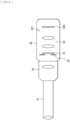
- FIG 1 schematically illustrates a configuration example of the optical phase modulator in the imaging optical system according to one embodiment of the present disclosure.
- FIG 2 schematically illustrates another configuration example of the optical phase modulator in the imaging optical system according to one embodiment.
- the optical phase modulator in the imaging optical system is, a depth extension device (BM: Birefringent Mask), and has an effect of extending a depth of field of the image-forming optical system.
- the imaging optical system according to one embodiment is an EDOF (Extended Depth of Focus) optical system having an extended depth of field by being equipped with the BM.
- EDOF Extended Depth of Focus
- the technique of the device itself of the BM is disclosed in PTL 4 described above, for example, as well.
- the technology according to the present disclosure is related to the WFC technique.
- the BM is an optical device having no refractive power, and includes an optical device substrate and a birefringent layer formed on a surface of the optical device substrate.
- the BM includes a glass substrate 12, and a BM layer 11 serving as a birefringent layer formed on a surface of the glass substrate 12.
- the BM may have a structure in which a birefringent layer is sandwiched between two optical device substrates like a sandwich.
- a structure in which the BM layer 11 serving as a birefringent layer is formed between two glass substrates 12 and 13 may be used.
- Using the sandwich-type structure makes it easy to apply AR coating or the like onto the glass substrate 13, for example, in the structure illustrated in FIG 2 , which reduces concerns for ghost and flare.
- FIG 3 schematically illustrates a configuration example of concentric pattern regions of the BM 10 in the imaging optical system according to one embodiment.
- the BM 10 does not have a structure like a concavo-convex shape for achievement of its effect.
- the BM layer 11 includes concentric pattern regions, as illustrated in FIG 3 , and has alignment in which a relative angle of birefringence anisotropy between the adjacent pattern regions is 90°.
- FIG 3 illustrates an example in which, a first concentric pattern region A1, a second concentric pattern region B1, and a third concentric pattern region A2 are formed in order from the center.
- the number of concentric pattern regions is not limited to three, and two or four or more may be formed.
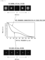
- FIG 4 schematically illustrate the optical characteristics of the optical phase modulator (the BM 10).
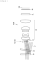
- FIG 5 schematically illustrates a configuration example of an imaging optical system according to Comparative Example (a normal optical system 102).
- FIG 6 schematically illustrates a configuration example of the imaging optical system (EDOF optical system) 101 according to one embodiment.
- the imaging optical system according to Comparative Example illustrated in FIG 5 includes an aperture stop St and an image-forming optical system 20.
- the imaging optical system according to Comparative Example illustrated in FIG 5 is the normal optical system 102 not including the BM 10 as a component.
- the imaging optical system 101 is, as compared with the configuration of the normal optical system 102, the EDOF optical system including the BM 10 near the aperture stop St.
- FIG 6 illustrates the configuration example in which the BM 10 is disposed on an imaging plane Sip side with respect to the aperture stop St
- a configuration in which the BM 10 is disposed on an object side with respect to the aperture stop St may also be used.
- FIG 6 illustrates the configuration example in which the image-forming optical system 20 is disposed on the imaging plane Sip side with respect to the aperture stop St
- some optical systems of the image-forming optical system 20 may be disposed on the object side with respect to the aperture stop St.
- An imaging apparatus equipped with such an imaging optical system 101 includes an image sensor disposed at a position of image formation by the imaging optical system 101, and an image processor 110 that performs, on an image captured by the image sensor, image processing using deconvolution derived from a PSF (Point Spread Function, point spread function) to be described later.
- PSF Point Spread Function, point spread function
- FIG. 4 illustrates an example of refractive indices applied to orthogonal two pieces of polarized light (X-polarized light and Y-polarized light) in the BM 10.
- B illustrates an example of phase modulation applied to each of the X-polarized light and the Y-polarized light by the BM 10.
- C illustrates, for each of the X-polarized light and the Y-polarized light, a through-focus MTF (Modulation transfer function) for a plurality of spatial frequencies.
- D of FIG. 4 illustrates, for each of the normal optical system 102 and the imaging optical system (EDOF optical system) 101 according to one embodiment, the through-focus MTF for the plurality of spatial frequencies.
- the first concentric pattern region A1 and the third concentric pattern region A2 have alignment in a Y direction
- the second concentric pattern region B1 has alignment in a X direction, as illustrated in FIG 3 .
- a refractive index of n is applied to the Y-polarized light
- a refractive index of n + ⁇ n is applied to the X-polarized light
- the second concentric pattern region B1 a refractive index of n + ⁇ n is applied to the Y-polarized light
- a refractive index of n is applied to the X-polarized light.
- Light that has passed through the BM 10 has different wavefronts between the X-polarized light and the Y-polarized light, and is caused to form an image by the image-forming optical system 20. Because of having different wavefronts between the X-polarized light and the Y-polarized light, as illustrated in FIG 6 , a light ray Lb of the X-polarized light and a light ray La of the Y-polarized light respectively form images at positions Pb and Pa before and after an image formation position P1 of the normal optical system 102.
- the through-focus MTF of each of the X-polarized light metethe Y-polarized light is as illustrated in (C) of FIG 4 .
- Image formation performance of the EDOF optical system as a whole is an average value of the X-polarized light and the Y-polarized light.
- the through-focus MTF obtained by averaging the through-focus MTF of each of the X-polarized light and the Y-polarized light in the EDOF optical system has a gentler shape than the through-focus MTF of the normal optical system 102, as illustrated in (D) of FIG 4 .
- the peak MTF decreases, because the wavefront in the EDOF optical system is not an ideal wavefront.
- the X-polarized light and the Y-polarized light having respective conjugate and different wavefronts form images. Therefore, it is possible to say that the EDOF optical system equipped with the BM 10 "have two pupil functions".
- the pupil functions P(u, v) of the EDOF optical system are given as follows in the first polarization state and the second polarization state.
- u and v are coordinates in the X direction and the Y direction on a pupil
- ⁇ (u, v) is the wavefront aberration of the image-forming optical system 20 in a state of not being equipped with the BM 10.
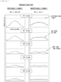
- FIG 7 illustrates, in comparison, optical characteristics of the imaging optical system according to Comparative Example (the normal optical system 102) and optical characteristics of the imaging optical system (EDOF optical system) 101 according to one embodiment.
- FIG 7 illustrates, as the optical characteristics, an example of the PSF and frequency characteristics of the MTF.
- FIG 8 illustrates, in comparison, the through-focus MTF of the imaging optical system according to Comparative Example (the normal optical system 102) and the through-focus MTF of the imaging optical system (EDOF optical system) 101 according to one embodiment.
- (A) of FIG 8 illustrates an example of the through-focus MTF of the imaging optical system according to Comparative Example (the normal optical system 102).
- (B) of FIG 8 illustrates an example of the through-focus MTF of the imaging optical system (EDOF optical system) 101 according to one embodiment.
- the MTF of the EDOF optical system has a lower peak value than that of the normal optical system 102. Therefore, in an imaging apparatus according to one embodiment, it is desirable to create a deconvolution filter (inverse transform filter) for image processing on the basis of the PSF of the EDOF optical system, and perform calculation processing using the deconvolution filter on an image captured via the EDOF optical system in the image processor 110 ( FIG 6 ). By performing this processing, it is possible to recover the MTF to the same level as that of the normal optical system 102, as illustrated in (B) of FIG 8 . In addition, the BM 10 is able to keep the high-frequency MTF at 0 or more at a just focus position. Therefore, if deconvolution processing for resolution recovery is applied, it is possible to achieve a limiting resolution comparable to that of the normal optical system 102 at the just focus position, as illustrated in (A) and (B) of FIG 8 .
- a deconvolution filter inverse transform filter
- the imaging optical system 101 is applicable to, for example, an endoscopic camera head of a rigid endoscope or the like, and a microscopic imaging camera unit.
- the imaging optical system 101 may be used as an optical system for capturing of an image formed by another afocal optical system or a substantially afocal optical system.
- An endoscope 31 is, for example, a rigid endoscope or a fiber scope.
- An eyepiece 32 is attached to the endoscope 31.
- the endoscopic camera head 30 is attached to the eyepiece 32.
- the endoscopic camera head 30 includes the imaging optical system 101 and an image sensor 100.
- An image captured by the image sensor 100 is subjected to image processing using deconvolution derived from the point spread function in the image processor 110 ( FIG. 6 ).
- FIG 10 schematically illustrates Application Example 2 of the imaging optical system 101 according to one embodiment to an imaging apparatus.
- FIG 10 illustrates a configuration example in which the imaging optical system 101 according to one embodiment is applied to a surgical microscopic imaging camera unit 40.
- a surgical microscope includes an eyepiece 41, an image-forming optical system 42, a prism 43, a zoom system 44, and an objective system 45. This surgical microscope enables observation by the naked eye via the eyepiece 41.
- the surgical microscopic imaging camera unit 40 is disposed on, for example, an optical path branched by the prism 43.
- the surgical microscopic imaging camera unit 40 includes the imaging optical system 101 and the image sensor 100.
- the surgical microscopic imaging camera unit 40 is used to image an affected area via the surgical microscope.
- An image captured by the image sensor 100 is subjected to image processing using deconvolution derived from the point spread function in the image processor 110 ( FIG 6 ).
- Described below is a desirable configuration example of the imaging optical system 101 according to one embodiment.
- a position where the BM 10 is allowed to be disposed is defined, for example, by a conditional expression (1), on the basis of an angle of incidence of a light ray on the aperture stop St. 1 ⁇ 2 ⁇ L ⁇ tan w + D / D ⁇ 1.4 where
- the peripheral light rays eccentrically enter the concentric pattern regions of the BM 10. Therefore, the phase modulation by the BM 10 is not concentric for the peripheral light rays, and the MTF greatly changes as compared with the center. In an eccentric direction, the peak value of the MTF decreases at high frequency. Assuming that an allowable value for the decrease in the peak value of the MTF is a ratio between the central MTF and the peripheral MTF of 70% or more, at a spatial frequency at which the central MTF is 10% or more, this allowable value holds by satisfying the conditional expression (1).
- FIG 13 illustrates an example of the through-focus MTF for a plurality of spatial frequencies of the imaging optical system 101 according to one embodiment.
- the retardation of the BM 10 is optimum within the range of the conditional expression (2).
- One reason for this is that, if the retardation exceeds the upper limit of the conditional expression (2), focus positions of the X-polarized light and the Y-polarized light are separated too much in a front-back direction, and the through-focus MTF has two peaks depending on the spatial frequency, as illustrated in FIG 13 . In such a state, the focus position is not definable in the first place, which results in difficulty of focusing by electronic calculation, such as AF (autofocus).
- AF autofocus
- the retardation falls below the lower limit of the conditional expression (2), it is difficult to exert a desired effect of the BM 10.
- the imaging optical system 101 be a medium telephoto lens with a focal length of 100 mm or more in 35 mm conversion. Satisfying a conditional expression (3) corresponds to the imaging optical system 101 being such a medium telephoto lens. h / f 2 ⁇ 0.50 where
- FIG 14 illustrates an overview of occurrence of flare and ghost in an imaging optical system 101A according to one embodiment.
- FIG 15 illustrates a configuration example that suppresses occurrence of flare and ghost in an imaging optical system 101B according to one embodiment.
- the imaging optical system 101A illustrated in FIG 14 illustrates, for example, a configuration example to be applied to the endoscopic camera head 30.
- an endoscope cover glass 33 and a camera head cover glass 34 are disposed on the object side of the imaging optical system 101A.
- the camera head cover glass 34 is disposed to be tilted.
- an optical filter FL and a seal glass SG are disposed on an optical path between the image-forming optical system 20 and the image sensor 100.
- the flat-shaped BM 10 is disposed perpendicular to an optical axis (not disposed to be tilted).
- the imaging optical system 101B illustrated in FIG 15 the BM 10 is disposed to be tilted.
- the configuration of the imaging optical system 101B is similar to the imaging optical system 101A, except that the BM 10 is disposed to be tilted.
- reflected light Lr reflected off the BM 10 and the optical device before or after the BM 10 can cause flare and ghost, as illustrated in FIG 14 .
- the reflected light Lr reflected off the BM 10 causes flare and ghost, which can result in a decrease in resolution performance, and misidentification of a subject due to an artifact.
- the BM 10 As a measure against this, it is desirable to dispose the BM 10 with such a tilt that lets the reflected light Lr causing ghost and flare out of an angle of view, as illustrated in FIG 15 . In this case, it is desirable that the BM 10 be disposed to be tilted to satisfy the following conditional expression. 1 ⁇ ⁇ / w 1 ⁇ 2 where
- the BM 10 be disposed to be tilted in a tilt direction that is opposite to a tilt direction of the optical device, such as the camera head cover glass 34, disposed to be tilted on the object side with respect to the BM 10.
- the imaging optical system 101 to be applied to an endoscope or a surgical microscope is a telephoto lens in many cases.
- a lens to be used in these applications is preferably small, and it is desirable that the imaging optical system 101 satisfy the following conditional expression. L_all / f 2 ⁇ 2.5 where
- a lens group farthest on the object side have positive power, and a lens group having negative power be disposed next.
- a telephoto-type configuration is achieved, making it possible to miniaturize the imaging optical system 101.
- FIG 16 illustrates an example of the passage range of the central light rays and the passage range of the peripheral light rays in the optical phase modulator (the BM 10) in a case where there is vignetting in the imaging optical system 101 according to one embodiment.
- FIG 17 illustrates an example of the central light rays and the peripheral light rays in a case where there is vignetting in the imaging optical system 101 according to one embodiment.
- vignetting occurs particularly for the peripheral light rays.
- the passage range of the peripheral light rays in the BM 10 becomes smaller than the passage range of the central light rays, and the passage range of the peripheral light rays loses circular symmetry.
- One reason for this is that, if the phase modulation of the BM 10 loses circular symmetry, it is no longer possible to exert intrinsic performance of the BM 10.
- a structure that blocks a light ray forming an image in an effective image circle of the imaging plane Sip after passing through the aperture stop St not be present between the aperture stop St and the imaging plane Sip.
- a diameter of the aperture structure be sufficiently larger than an optical effective diameter when the light ray forming an image in the effective image circle passes through the aperture structure.
- the BM 10 gives the two pupil functions to the image-forming optical system 20. This makes it possible to extend the depth of field while suppressing a decrease in the resolution performance.
- the imaging optical system 101 enables optimum depth of field extension with the resolution performance comparable to that of the normal optical system 102. If an appropriate measure against ghost is taken in the imaging optical system 101 according to one embodiment, it is possible to suppress a decrease in contrast and an adverse effect of a double image or the like, enabling an improvement in the image quality.
- imaging optical system 101 Described next are specific numerical examples of the imaging optical system 101 according to one embodiment of the present disclosure. It is to be noted that, in the following, substantially the same portions as the components of the imaging optical system 101 according to one embodiment are denoted with the same reference numerals, and description thereof is omitted as appropriate.
- Imaging optical systems 1 to 3 each include the aperture stop St, the BM 10, and the image-forming optical system 20, in order from the object side toward the imaging plane Sip side.
- the optical filter FL and the seal glass SG are disposed on an optical path between the image-forming optical system 20 and the imaging plane Sip.
- the BM 10 is disposed to be tilted. In the imaging optical system 3 according to Example 3, the BM 10 is not disposed to be tilted. In each of the imaging optical systems 1 to 3 according to Examples 1 to 3, the BM 10 includes the first concentric pattern region A1 and the second concentric pattern region B1.
- the image sensor 100 is disposed on the imaging plane Sip. An image captured by the image sensor 100 is subjected to image processing using an inverse transform filter in the image processor 110 ( FIG 6 ).
- FIG 18 schematically illustrates the concentric pattern regions of the BM 10 and the diameter of the aperture stop St in the imaging optical system 1 according to Example 1.
- FIG 19 illustrates an overall configuration of the imaging optical system 1 according to Example 1.
- the image-forming optical system 20 includes a first lens G1, a second lens G2, a third lens G3, a fourth lens G4, a fifth lens G5, and a sixth lens G6, in order from the object side toward the imaging plane Sip side.
- the first lens G1 and the second lens G2 are cemented to each other.
- the fourth lens G4 and the fifth lens G5 are cemented to each other.
- the cemented lens including the first lens G1 and the second lens G2 is a lens group having positive power.
- the third lens G3 is a lens group having negative power.
- [Table 1] shows basic lens data of the imaging optical system 1 according to Example 1.
- "Si” indicates a surface number meaning an i-th surface counted from the object side. The surface number is affixed with an attribute of the surface.
- "G1R1” indicates a lens surface on the object side of the first lens G1
- "G1R2” indicates a lens surface on the imaging plane Sip side of the first lens G1.
- “G2R1” indicates a lens surface on the object side of the second lens G2
- “G2R2” indicates a lens surface on the imaging plane Sip side of the second lens G2. The same applies to other lens surfaces and optical surfaces.
- ri indicates a curvature radius (unit: mm) of the i-th surface counted from the object side.
- a portion where the value of "ri” is “ ⁇ ” indicates the aperture stop St, a flat surface, or a virtual surface.
- di indicates an on-axis surface interval (unit: mm) between the i-th surface and an i+1-th surface counted from the object side.
- ndi indicates a refractive index for the d line (wavelength 587.6 nm) of a glass material or a material having the i-th surface on the object side.
- vdi indicates an Abbe number for the d line of a glass material or a material having the i-th surface on the object side. The same applies to lens data in other Examples below.
- [Table 2] shows values of a focal length (f) of the whole system, an aperture diameter (D) of the aperture stop St (see FIG 18 ), an open F-number (Fno), and an image height (IH) in the imaging optical system 1 according to Example 1.
- [Table 2] shows values of a radius (Ring1) of the first concentric pattern region A1 (see FIG 18 ), a radius (Ring2) of the second concentric pattern region B1 (see FIG 18 ), and retardation (Re) of the optical phase modulator (the BM 10).
- FIG 20 illustrates the through-focus MTF of the imaging optical system 1 according to Example 1.
- FIG 20 illustrates the through-focus MTF related to the spatial frequency (100 (Lp/mm)) at which the BM 10 exerts the strongest influence.
- FIG 20 illustrates, as the through-focus MTF of the imaging optical system 1 according to Example 1, characteristics in a case where image processing has not been performed (with depth extension (without image processing)), and characteristics in a case where the image processing using the inverse transform filter has been performed (with depth extension (with image processing)).
- FIG 20 illustrates, as Comparative Example, the through-focus MTF of an optical system not including the BM 10 (without depth extension).
- the imaging optical system 1 according to Example 1 exhibits a great decrease in the peak of the through-focus MTF, as compared with the optical system not including the BM 10.
- the use of the inverse transform filter to apply ideal deconvolution processing for recovery of the same resolution as the optical system not including the BM 10 has made it possible to return the peak of the through-focus MTF to a peak equivalent to that of the optical system not including the BM 10, and to greatly extend the depth.
- FIG 21 illustrates the frequency characteristics of the MTF at the focus position of the imaging optical system 1 according to Example 1.
- FIG 21 illustrates, with a solid line, characteristics in the case where image processing has not been performed (with depth extension (without image processing)), as the frequency characteristics of the MTF of the imaging optical system 1 according to Example 1.
- FIG 21 illustrates, as Comparative Example, the frequency characteristics of the MTF of the optical system not including the BM 10 (without depth extension).
- FIG 21 illustrates the frequency characteristics of the inverse transform filter to be used to apply the ideal deconvolution processing for recovery of the same resolution as the optical system not including the BM 10. The same applies to the frequency characteristics of the MTF in other Examples below.
- the imaging optical system 1 according to Example 1 exhibits a decrease in the frequency characteristics of the MTF, as compared with the optical system not including the BM 10.
- the use of the inverse transform filter to apply the ideal deconvolution processing for recovery of the same resolution as the optical system not including the BM 10 has made it possible to return the frequency characteristics of the MTF to frequency characteristics substantially equivalent to those of the optical system not including the BM 10.
- FIG 22 schematically illustrates the concentric pattern regions of the BM 10 and the diameter of the aperture stop St in the imaging optical system 2 according to Example 2.
- FIG 23 illustrates an overall configuration of the imaging optical system 2 according to Example 2.
- the imaging optical system 2 according to Example 2 has substantially the same configuration as the imaging optical system 1 according to Example 1, but the aperture diameter (D) of the aperture stop St is varied from that in the imaging optical system 1 according to Example 1.
- the imaging optical system 2 according to Example 2 indicates that changing the aperture diameter of the aperture stop St result in a change in the effect of the depth extension.
- [Table 3] shows basic lens data of the imaging optical system 2 according to Example 2.
- [Table 4] shows values of a focal length (f) of the whole system, an aperture diameter (D) of the aperture stop St (see FIG 22 ), an open F-number (Fno), and an image height (IH) in the imaging optical system 2 according to Example 2.
- [Table 4] shows values of a radius (Ring1) of the first concentric pattern region A1 (see FIG 22 ), a radius (Ring2) of the second concentric pattern region B1 (see FIG 22 ), and retardation (Re) of the optical phase modulator (the BM 10).
- FIG 24 illustrates the through-focus MTF of the imaging optical system 2 according to Example 2.
- FIG 24 illustrates the through-focus MTF related to the spatial frequency (100 (Lp/mm)) at which the BM 10 exerts the strongest influence.
- FIG 24 illustrates, as the through-focus MTF of the imaging optical system 2 according to Example 2, characteristics in a case where image processing has not been performed (with depth extension (without image processing)), and characteristics in a case where the image processing using the inverse transform filter has been performed (with depth extension (with image processing)).
- FIG 24 illustrates, as Comparative Example, the through-focus MTF of an optical system not including the BM 10 (without depth extension).
- the imaging optical system 2 according to Example 2 exhibits a great decrease in the peak of the through-focus MTF, as compared with the optical system not including the BM 10.
- the use of the inverse transform filter to apply ideal deconvolution processing for recovery of the same resolution as the optical system not including the BM 10 has made it possible to return the peak of the through-focus MTF to a peak equivalent to that of the optical system not including the BM 10, and to greatly extend the depth.
- FIG 25 illustrates the frequency characteristics of the MTF at the focus position of the imaging optical system 2 according to Example 2.
- the imaging optical system 2 according to Example 2 exhibits a decrease in the frequency characteristics of the MTF, as compared with the optical system not including the BM 10.
- the use of the inverse transform filter to apply the ideal deconvolution processing for recovery of the same resolution as the optical system not including the BM 10 has made it possible to return the frequency characteristics of the MTF to frequency characteristics substantially equivalent to those of the optical system not including the BM 10.
- FIG 26 schematically illustrates the concentric pattern regions of the optical phase modulator (the BM 10) and the diameter of the aperture stop St in the imaging optical system 3 according to Example 3.
- FIG 27 illustrates a configuration of the imaging optical system 3 according to Example 3.
- the image-forming optical system 20 includes a first lens G1, a second lens G2, a third lens G3, a fourth lens G4, and a fifth lens G5, in order from the object side toward the imaging plane Sip side.
- Each lens is a single lens.
- the first lens G1 is a lens group having positive power.
- the second lens G2 is a lens group having negative power.
- [Table 5] shows basic lens data of the imaging optical system 3 according to Example 3.
- [Table 6] shows values of a focal length (f) of the whole system, an aperture diameter (D) of the aperture stop St (see FIG 26 ), an open F-number (Fno), and an image height (IH) in the imaging optical system 3 according to Example 3.
- [Table 6] shows values of a radius (Ring1) of the first concentric pattern region (see FIG 26 ), a radius (Ring2) of the second concentric pattern region (see FIG 26 ), and retardation (Re) of the optical phase modulator (the BM 10).
- FIG 28 illustrates the through-focus MTF of the imaging optical system 3 according to Example 3.
- FIG 28 illustrates the through-focus MTF related to the spatial frequency (40 (Lp/mm)) at which the BM 10 exerts the strongest influence.
- FIG 28 illustrates, as the through-focus MTF of the imaging optical system 3 according to Example 3, characteristics in a case where image processing has not been performed (with depth extension (without image processing)), and characteristics in a case where the image processing using the inverse transform filter has been performed (with depth extension (with image processing)).
- FIG 28 illustrates, as Comparative Example, the through-focus MTF of an optical system not including the BM 10 (without depth extension).
- the imaging optical system 3 according to Example 3 exhibits a great decrease in the peak of the through-focus MTF, as compared with the optical system not including the BM 10.
- the use of the inverse transform filter to apply ideal deconvolution processing for recovery of the same resolution as the optical system not including the BM 10 has made it possible to return the peak of the through-focus MTF to a peak equivalent to that of the optical system not including the BM 10, and to greatly extend the depth.
- FIG 29 illustrates the frequency characteristics of the MTF at the focus position of the imaging optical system 3 according to Example 3.
- the imaging optical system 3 according to Example 3 exhibits a decrease in the frequency characteristics of the MTF, as compared with the optical system not including the BM 10.
- the use of the inverse transform filter to apply the ideal deconvolution processing for recovery of the same resolution as the optical system not including the BM 10 has made it possible to return the frequency characteristics of the MTF to frequency characteristics substantially equivalent to those of the optical system not including the BM 10.
- Example 7 summarizes, for each of Examples, values related to the conditional expressions given above. It is apparent from [Table 7] that Examples 1 and 2 satisfy the conditional expressions. Example 3 satisfy the conditional expressions except for the conditional expression (4).
- Conditional expression Example 1 2 3 (1) L(mm) 1 1 0.02 w(°) 10.204 10.204 8.881 D(mm) 4 2.4 1.5 (2 ⁇ L ⁇ tan(w)+D)/D 1.090 1.150 1.004 (2) ⁇ (nm) 550 550 550 Re(nm) 119.7 119.7 119.7 (3) h/f2 0.18 0.18 0.156 (4) Imaging plane short-side length(mm) 1.76 1.76 1.77 ⁇ (°) 9.00 9.00 0 w1(°) 5.04 5.04 6.30 ⁇ /w1 1.78 1.78 0 (5) L_all/f2 1.435 1.435 1.206 ⁇ 6.
- the shapes and numerical values of the respective parts described above in Examples are mere examples of the implementation of the present technology, and the technical scope of the present technology should not be construed as being limited by these examples.
- the optical phase modulator gives the two pupil functions to the image-forming optical system. This makes it possible to extend the depth of field while suppressing a decrease in the resolution performance.
Landscapes
- Physics & Mathematics (AREA)
- Optics & Photonics (AREA)
- General Physics & Mathematics (AREA)
- Health & Medical Sciences (AREA)
- Life Sciences & Earth Sciences (AREA)
- Astronomy & Astrophysics (AREA)
- Lenses (AREA)
- Surgery (AREA)
- Engineering & Computer Science (AREA)
- Animal Behavior & Ethology (AREA)
- Veterinary Medicine (AREA)
- Pathology (AREA)
- Radiology & Medical Imaging (AREA)
- Biophysics (AREA)
- Biomedical Technology (AREA)
- Heart & Thoracic Surgery (AREA)
- Medical Informatics (AREA)
- Molecular Biology (AREA)
- Nuclear Medicine, Radiotherapy & Molecular Imaging (AREA)
- General Health & Medical Sciences (AREA)
- Public Health (AREA)
- Instruments For Viewing The Inside Of Hollow Bodies (AREA)
- Microscoopes, Condenser (AREA)
- Polarising Elements (AREA)
- Endoscopes (AREA)
- Studio Devices (AREA)
- Signal Processing (AREA)
Applications Claiming Priority (2)
| Application Number | Priority Date | Filing Date | Title |
|---|---|---|---|
| JP2019174200 | 2019-09-25 | ||
| PCT/JP2020/030000 WO2021059763A1 (ja) | 2019-09-25 | 2020-08-05 | 撮像光学系、および撮像装置 |
Publications (3)
| Publication Number | Publication Date |
|---|---|
| EP4012471A1 EP4012471A1 (en) | 2022-06-15 |
| EP4012471A4 EP4012471A4 (en) | 2022-10-05 |
| EP4012471B1 true EP4012471B1 (en) | 2025-05-07 |
Family
ID=75164967
Family Applications (1)
| Application Number | Title | Priority Date | Filing Date |
|---|---|---|---|
| EP20868379.7A Active EP4012471B1 (en) | 2019-09-25 | 2020-08-05 | Imaging optical system and imaging device |
Country Status (4)
| Country | Link |
|---|---|
| US (1) | US12270975B2 (https=) |
| EP (1) | EP4012471B1 (https=) |
| JP (1) | JP7501538B2 (https=) |
| WO (1) | WO2021059763A1 (https=) |
Families Citing this family (1)
| Publication number | Priority date | Publication date | Assignee | Title |
|---|---|---|---|---|
| US20250060576A1 (en) * | 2021-12-21 | 2025-02-20 | Leica Instruments (Singapore) Pte. Ltd. | Microscope System and Corresponding Method |
Family Cites Families (11)
| Publication number | Priority date | Publication date | Assignee | Title |
|---|---|---|---|---|
| JP4700304B2 (ja) * | 2004-08-10 | 2011-06-15 | オリンパス株式会社 | カメラヘッド |
| WO2007122615A2 (en) * | 2006-04-20 | 2007-11-01 | Xceed Imaging Ltd. | All optical system and method for providing extended depth of focus of imaging |
| JP2010271689A (ja) | 2009-04-21 | 2010-12-02 | Fujifilm Corp | 位相補正板、撮像システム、撮像装置、携帯電話、車載機器、監視カメラ、内視鏡装置、デジタルカメラ、デジタルビデオカメラ、およびレンズユニット |
| US20120281280A1 (en) | 2009-10-15 | 2012-11-08 | Sony Corporation | Birefringent device with application specific pupil function and optical device |
| JP6115350B2 (ja) | 2013-06-21 | 2017-04-19 | 株式会社リコー | 撮像装置および撮像方法および撮像装置用の結像光学系 |
| US9625632B2 (en) | 2015-03-31 | 2017-04-18 | Sony Corporation | Camera, optical system and interchangeable lens with birefringent device |
| JP2017158764A (ja) | 2016-03-09 | 2017-09-14 | ソニー株式会社 | 画像処理装置、画像処理方法、及び記録媒体 |
| WO2018109117A1 (en) * | 2016-12-16 | 2018-06-21 | Sony Corporation | Capturing an image of a scene |
| JP6786377B2 (ja) | 2016-12-21 | 2020-11-18 | 株式会社日立製作所 | 光学部品およびそれを用いた撮像システム |
| WO2019044328A1 (ja) * | 2017-08-31 | 2019-03-07 | ソニー株式会社 | 医療用画像処理装置、医療用画像処理システム、及び医療用画像処理装置の駆動方法 |
| JP6951753B2 (ja) | 2018-03-27 | 2021-10-20 | エバ・ジャパン 株式会社 | 情報探索システム及びプログラム |
-
2020
- 2020-08-05 JP JP2021548407A patent/JP7501538B2/ja active Active
- 2020-08-05 EP EP20868379.7A patent/EP4012471B1/en active Active
- 2020-08-05 US US17/753,824 patent/US12270975B2/en active Active
- 2020-08-05 WO PCT/JP2020/030000 patent/WO2021059763A1/ja not_active Ceased
Also Published As
| Publication number | Publication date |
|---|---|
| JP7501538B2 (ja) | 2024-06-18 |
| US20220346631A1 (en) | 2022-11-03 |
| JPWO2021059763A1 (https=) | 2021-04-01 |
| EP4012471A4 (en) | 2022-10-05 |
| US12270975B2 (en) | 2025-04-08 |
| EP4012471A1 (en) | 2022-06-15 |
| WO2021059763A1 (ja) | 2021-04-01 |
Similar Documents
| Publication | Publication Date | Title |
|---|---|---|
| JP3765500B2 (ja) | 内視鏡用対物レンズ | |
| US8456767B2 (en) | Objective optical system | |
| JP4659645B2 (ja) | 拡大内視鏡光学系 | |
| US9097850B2 (en) | Endoscope objective lens | |
| JPH07191265A (ja) | 内視鏡光学系 | |
| CN107589534B (zh) | 一种透镜系统及镜头 | |
| CN109416459A (zh) | 内窥镜物镜光学系统 | |
| JP2009163256A (ja) | 光学系 | |
| JPH0526487B2 (https=) | ||
| EP4012471B1 (en) | Imaging optical system and imaging device | |
| JPH0558527B2 (https=) | ||
| JP2012234056A (ja) | 結像レンズ、撮像光学系、及び、顕微鏡 | |
| WO2021084835A1 (ja) | 光学系及び光学機器 | |
| JP2009020220A (ja) | ファインダー光学系、これを備える光学機器及びこれを用いた観察方法 | |
| JP2004020972A (ja) | 撮影光学系およびそれを用いた内視鏡 | |
| JP4683212B2 (ja) | 魚眼レンズ及び撮像装置 | |
| JP4683213B2 (ja) | 魚眼レンズ及び撮像装置 | |
| JP3897457B2 (ja) | 立体画像撮影用光学系およびそれに用いるズームレンズ | |
| CN221266120U (zh) | 内窥镜光学系统和立体内窥镜 | |
| JPH05288985A (ja) | 内視鏡用対物レンズ | |
| JP4742373B2 (ja) | 撮影光学系および鏡筒 | |
| CN222672044U (zh) | 一种荧光摄像卡口及内窥镜系统 | |
| JP2876222B2 (ja) | 撮像光学系 | |
| JPH04163509A (ja) | 内視鏡対物光学系 | |
| JP2008107380A (ja) | ズームビューファインダ及び撮像装置 |
Legal Events
| Date | Code | Title | Description |
|---|---|---|---|
| STAA | Information on the status of an ep patent application or granted ep patent |
Free format text: STATUS: THE INTERNATIONAL PUBLICATION HAS BEEN MADE |
|
| PUAI | Public reference made under article 153(3) epc to a published international application that has entered the european phase |
Free format text: ORIGINAL CODE: 0009012 |
|
| STAA | Information on the status of an ep patent application or granted ep patent |
Free format text: STATUS: REQUEST FOR EXAMINATION WAS MADE |
|
| 17P | Request for examination filed |
Effective date: 20220310 |
|
| AK | Designated contracting states |
Kind code of ref document: A1 Designated state(s): AL AT BE BG CH CY CZ DE DK EE ES FI FR GB GR HR HU IE IS IT LI LT LU LV MC MK MT NL NO PL PT RO RS SE SI SK SM TR |
|
| A4 | Supplementary search report drawn up and despatched |
Effective date: 20220902 |
|
| RIC1 | Information provided on ipc code assigned before grant |
Ipc: G02B 23/24 20060101ALI20220829BHEP Ipc: H04N 5/232 20060101ALI20220829BHEP Ipc: H04N 5/225 20060101ALI20220829BHEP Ipc: G02B 23/26 20060101ALI20220829BHEP Ipc: G02B 21/36 20060101ALI20220829BHEP Ipc: G02B 5/30 20060101ALI20220829BHEP Ipc: A61B 1/00 20060101ALI20220829BHEP Ipc: G02B 13/00 20060101AFI20220829BHEP |
|
| DAV | Request for validation of the european patent (deleted) | ||
| DAX | Request for extension of the european patent (deleted) | ||
| GRAP | Despatch of communication of intention to grant a patent |
Free format text: ORIGINAL CODE: EPIDOSNIGR1 |
|
| STAA | Information on the status of an ep patent application or granted ep patent |
Free format text: STATUS: GRANT OF PATENT IS INTENDED |
|
| RIC1 | Information provided on ipc code assigned before grant |
Ipc: G02B 27/00 20060101ALI20241127BHEP Ipc: G02B 21/00 20060101ALI20241127BHEP Ipc: G02B 21/22 20060101ALI20241127BHEP Ipc: G02B 5/00 20060101ALI20241127BHEP Ipc: G02B 23/24 20060101ALI20241127BHEP Ipc: G02B 23/26 20060101ALI20241127BHEP Ipc: G02B 21/36 20060101ALI20241127BHEP Ipc: G02B 5/30 20060101ALI20241127BHEP Ipc: A61B 1/00 20060101ALI20241127BHEP Ipc: G02B 13/00 20060101AFI20241127BHEP |
|
| INTG | Intention to grant announced |
Effective date: 20241210 |
|
| GRAS | Grant fee paid |
Free format text: ORIGINAL CODE: EPIDOSNIGR3 |
|
| GRAA | (expected) grant |
Free format text: ORIGINAL CODE: 0009210 |
|
| STAA | Information on the status of an ep patent application or granted ep patent |
Free format text: STATUS: THE PATENT HAS BEEN GRANTED |
|
| P01 | Opt-out of the competence of the unified patent court (upc) registered |
Free format text: CASE NUMBER: APP_13591/2025 Effective date: 20250319 |
|
| AK | Designated contracting states |
Kind code of ref document: B1 Designated state(s): AL AT BE BG CH CY CZ DE DK EE ES FI FR GB GR HR HU IE IS IT LI LT LU LV MC MK MT NL NO PL PT RO RS SE SI SK SM TR |
|
| REG | Reference to a national code |
Ref country code: GB Ref legal event code: FG4D |
|
| REG | Reference to a national code |
Ref country code: CH Ref legal event code: EP |
|
| REG | Reference to a national code |
Ref country code: DE Ref legal event code: R096 Ref document number: 602020051048 Country of ref document: DE |
|
| REG | Reference to a national code |
Ref country code: IE Ref legal event code: FG4D |
|
| REG | Reference to a national code |
Ref country code: NL Ref legal event code: MP Effective date: 20250507 |
|
| PG25 | Lapsed in a contracting state [announced via postgrant information from national office to epo] |
Ref country code: ES Free format text: LAPSE BECAUSE OF FAILURE TO SUBMIT A TRANSLATION OF THE DESCRIPTION OR TO PAY THE FEE WITHIN THE PRESCRIBED TIME-LIMIT Effective date: 20250507 Ref country code: PT Free format text: LAPSE BECAUSE OF FAILURE TO SUBMIT A TRANSLATION OF THE DESCRIPTION OR TO PAY THE FEE WITHIN THE PRESCRIBED TIME-LIMIT Effective date: 20250908 Ref country code: FI Free format text: LAPSE BECAUSE OF FAILURE TO SUBMIT A TRANSLATION OF THE DESCRIPTION OR TO PAY THE FEE WITHIN THE PRESCRIBED TIME-LIMIT Effective date: 20250507 |
|
| PGFP | Annual fee paid to national office [announced via postgrant information from national office to epo] |
Ref country code: DE Payment date: 20250724 Year of fee payment: 6 |
|
| REG | Reference to a national code |
Ref country code: LT Ref legal event code: MG9D |
|
| PG25 | Lapsed in a contracting state [announced via postgrant information from national office to epo] |
Ref country code: GR Free format text: LAPSE BECAUSE OF FAILURE TO SUBMIT A TRANSLATION OF THE DESCRIPTION OR TO PAY THE FEE WITHIN THE PRESCRIBED TIME-LIMIT Effective date: 20250808 Ref country code: NO Free format text: LAPSE BECAUSE OF FAILURE TO SUBMIT A TRANSLATION OF THE DESCRIPTION OR TO PAY THE FEE WITHIN THE PRESCRIBED TIME-LIMIT Effective date: 20250807 |
|
| PG25 | Lapsed in a contracting state [announced via postgrant information from national office to epo] |
Ref country code: PL Free format text: LAPSE BECAUSE OF FAILURE TO SUBMIT A TRANSLATION OF THE DESCRIPTION OR TO PAY THE FEE WITHIN THE PRESCRIBED TIME-LIMIT Effective date: 20250507 Ref country code: NL Free format text: LAPSE BECAUSE OF FAILURE TO SUBMIT A TRANSLATION OF THE DESCRIPTION OR TO PAY THE FEE WITHIN THE PRESCRIBED TIME-LIMIT Effective date: 20250507 |
|
| REG | Reference to a national code |
Ref country code: AT Ref legal event code: MK05 Ref document number: 1793077 Country of ref document: AT Kind code of ref document: T Effective date: 20250507 |
|
| PG25 | Lapsed in a contracting state [announced via postgrant information from national office to epo] |
Ref country code: BG Free format text: LAPSE BECAUSE OF FAILURE TO SUBMIT A TRANSLATION OF THE DESCRIPTION OR TO PAY THE FEE WITHIN THE PRESCRIBED TIME-LIMIT Effective date: 20250507 |
|
| PG25 | Lapsed in a contracting state [announced via postgrant information from national office to epo] |
Ref country code: HR Free format text: LAPSE BECAUSE OF FAILURE TO SUBMIT A TRANSLATION OF THE DESCRIPTION OR TO PAY THE FEE WITHIN THE PRESCRIBED TIME-LIMIT Effective date: 20250507 |
|
| PG25 | Lapsed in a contracting state [announced via postgrant information from national office to epo] |
Ref country code: AT Free format text: LAPSE BECAUSE OF FAILURE TO SUBMIT A TRANSLATION OF THE DESCRIPTION OR TO PAY THE FEE WITHIN THE PRESCRIBED TIME-LIMIT Effective date: 20250507 |
|
| PG25 | Lapsed in a contracting state [announced via postgrant information from national office to epo] |
Ref country code: RS Free format text: LAPSE BECAUSE OF FAILURE TO SUBMIT A TRANSLATION OF THE DESCRIPTION OR TO PAY THE FEE WITHIN THE PRESCRIBED TIME-LIMIT Effective date: 20250807 |
|
| PG25 | Lapsed in a contracting state [announced via postgrant information from national office to epo] |
Ref country code: IS Free format text: LAPSE BECAUSE OF FAILURE TO SUBMIT A TRANSLATION OF THE DESCRIPTION OR TO PAY THE FEE WITHIN THE PRESCRIBED TIME-LIMIT Effective date: 20250907 |
|
| PG25 | Lapsed in a contracting state [announced via postgrant information from national office to epo] |
Ref country code: LV Free format text: LAPSE BECAUSE OF FAILURE TO SUBMIT A TRANSLATION OF THE DESCRIPTION OR TO PAY THE FEE WITHIN THE PRESCRIBED TIME-LIMIT Effective date: 20250507 |
|
| PG25 | Lapsed in a contracting state [announced via postgrant information from national office to epo] |
Ref country code: DK Free format text: LAPSE BECAUSE OF FAILURE TO SUBMIT A TRANSLATION OF THE DESCRIPTION OR TO PAY THE FEE WITHIN THE PRESCRIBED TIME-LIMIT Effective date: 20250507 Ref country code: SM Free format text: LAPSE BECAUSE OF FAILURE TO SUBMIT A TRANSLATION OF THE DESCRIPTION OR TO PAY THE FEE WITHIN THE PRESCRIBED TIME-LIMIT Effective date: 20250507 |
|
| PG25 | Lapsed in a contracting state [announced via postgrant information from national office to epo] |
Ref country code: CZ Free format text: LAPSE BECAUSE OF FAILURE TO SUBMIT A TRANSLATION OF THE DESCRIPTION OR TO PAY THE FEE WITHIN THE PRESCRIBED TIME-LIMIT Effective date: 20250507 |
|
| PG25 | Lapsed in a contracting state [announced via postgrant information from national office to epo] |
Ref country code: EE Free format text: LAPSE BECAUSE OF FAILURE TO SUBMIT A TRANSLATION OF THE DESCRIPTION OR TO PAY THE FEE WITHIN THE PRESCRIBED TIME-LIMIT Effective date: 20250507 |
|
| PG25 | Lapsed in a contracting state [announced via postgrant information from national office to epo] |
Ref country code: SK Free format text: LAPSE BECAUSE OF FAILURE TO SUBMIT A TRANSLATION OF THE DESCRIPTION OR TO PAY THE FEE WITHIN THE PRESCRIBED TIME-LIMIT Effective date: 20250507 Ref country code: RO Free format text: LAPSE BECAUSE OF FAILURE TO SUBMIT A TRANSLATION OF THE DESCRIPTION OR TO PAY THE FEE WITHIN THE PRESCRIBED TIME-LIMIT Effective date: 20250507 |
|
| PG25 | Lapsed in a contracting state [announced via postgrant information from national office to epo] |
Ref country code: IT Free format text: LAPSE BECAUSE OF FAILURE TO SUBMIT A TRANSLATION OF THE DESCRIPTION OR TO PAY THE FEE WITHIN THE PRESCRIBED TIME-LIMIT Effective date: 20250507 |
|
| REG | Reference to a national code |
Ref country code: DE Ref legal event code: R097 Ref document number: 602020051048 Country of ref document: DE |
|
| PLBE | No opposition filed within time limit |
Free format text: ORIGINAL CODE: 0009261 |
|
| STAA | Information on the status of an ep patent application or granted ep patent |
Free format text: STATUS: NO OPPOSITION FILED WITHIN TIME LIMIT |
|
| REG | Reference to a national code |
Ref country code: CH Ref legal event code: L10 Free format text: ST27 STATUS EVENT CODE: U-0-0-L10-L00 (AS PROVIDED BY THE NATIONAL OFFICE) Effective date: 20260318 |
|
| REG | Reference to a national code |
Ref country code: CH Ref legal event code: H13 Free format text: ST27 STATUS EVENT CODE: U-0-0-H10-H13 (AS PROVIDED BY THE NATIONAL OFFICE) Effective date: 20260324 |
|
| PG25 | Lapsed in a contracting state [announced via postgrant information from national office to epo] |
Ref country code: MC Free format text: LAPSE BECAUSE OF FAILURE TO SUBMIT A TRANSLATION OF THE DESCRIPTION OR TO PAY THE FEE WITHIN THE PRESCRIBED TIME-LIMIT Effective date: 20250507 |
|
| 26N | No opposition filed |
Effective date: 20260210 |
|
| PG25 | Lapsed in a contracting state [announced via postgrant information from national office to epo] |
Ref country code: LU Free format text: LAPSE BECAUSE OF NON-PAYMENT OF DUE FEES Effective date: 20250805 |
|
| PG25 | Lapsed in a contracting state [announced via postgrant information from national office to epo] |
Ref country code: CH Free format text: LAPSE BECAUSE OF NON-PAYMENT OF DUE FEES Effective date: 20250831 |