EP4012200A1 - Spring-loaded detent bolt - Google Patents
Spring-loaded detent bolt Download PDFInfo
- Publication number
- EP4012200A1 EP4012200A1 EP21202818.7A EP21202818A EP4012200A1 EP 4012200 A1 EP4012200 A1 EP 4012200A1 EP 21202818 A EP21202818 A EP 21202818A EP 4012200 A1 EP4012200 A1 EP 4012200A1
- Authority
- EP
- European Patent Office
- Prior art keywords
- sleeve
- locking
- actuating
- guide
- guide sleeve
- Prior art date
- Legal status (The legal status is an assumption and is not a legal conclusion. Google has not performed a legal analysis and makes no representation as to the accuracy of the status listed.)
- Granted
Links
- 230000006835 compression Effects 0.000 claims abstract description 18
- 238000007906 compression Methods 0.000 claims abstract description 18
- 230000007935 neutral effect Effects 0.000 claims abstract description 15
- 238000011161 development Methods 0.000 description 12
- 230000018109 developmental process Effects 0.000 description 12
- 230000000295 complement effect Effects 0.000 description 5
- 230000000903 blocking effect Effects 0.000 description 4
- 230000001419 dependent effect Effects 0.000 description 2
- 238000006073 displacement reaction Methods 0.000 description 1
- 230000000694 effects Effects 0.000 description 1
- 238000003780 insertion Methods 0.000 description 1
- 230000037431 insertion Effects 0.000 description 1
- 238000009434 installation Methods 0.000 description 1
- 230000000149 penetrating effect Effects 0.000 description 1
Images


Classifications
-
- F—MECHANICAL ENGINEERING; LIGHTING; HEATING; WEAPONS; BLASTING
- F16—ENGINEERING ELEMENTS AND UNITS; GENERAL MEASURES FOR PRODUCING AND MAINTAINING EFFECTIVE FUNCTIONING OF MACHINES OR INSTALLATIONS; THERMAL INSULATION IN GENERAL
- F16B—DEVICES FOR FASTENING OR SECURING CONSTRUCTIONAL ELEMENTS OR MACHINE PARTS TOGETHER, e.g. NAILS, BOLTS, CIRCLIPS, CLAMPS, CLIPS OR WEDGES; JOINTS OR JOINTING
- F16B19/00—Bolts without screw-thread; Pins, including deformable elements; Rivets
- F16B19/04—Rivets; Spigots or the like fastened by riveting
- F16B19/08—Hollow rivets; Multi-part rivets
- F16B19/10—Hollow rivets; Multi-part rivets fastened by expanding mechanically
- F16B19/1027—Multi-part rivets
- F16B19/1036—Blind rivets
- F16B19/109—Temporary rivets, e.g. with a spring-loaded pin
-
- F—MECHANICAL ENGINEERING; LIGHTING; HEATING; WEAPONS; BLASTING
- F16—ENGINEERING ELEMENTS AND UNITS; GENERAL MEASURES FOR PRODUCING AND MAINTAINING EFFECTIVE FUNCTIONING OF MACHINES OR INSTALLATIONS; THERMAL INSULATION IN GENERAL
- F16B—DEVICES FOR FASTENING OR SECURING CONSTRUCTIONAL ELEMENTS OR MACHINE PARTS TOGETHER, e.g. NAILS, BOLTS, CIRCLIPS, CLAMPS, CLIPS OR WEDGES; JOINTS OR JOINTING
- F16B21/00—Means for preventing relative axial movement of a pin, spigot, shaft or the like and a member surrounding it; Stud-and-socket releasable fastenings
- F16B21/10—Means for preventing relative axial movement of a pin, spigot, shaft or the like and a member surrounding it; Stud-and-socket releasable fastenings by separate parts
- F16B21/16—Means for preventing relative axial movement of a pin, spigot, shaft or the like and a member surrounding it; Stud-and-socket releasable fastenings by separate parts with grooves or notches in the pin or shaft
- F16B21/18—Means for preventing relative axial movement of a pin, spigot, shaft or the like and a member surrounding it; Stud-and-socket releasable fastenings by separate parts with grooves or notches in the pin or shaft with circlips or like resilient retaining devices, i.e. resilient in the plane of the ring or the like; Details
- F16B21/183—Means for preventing relative axial movement of a pin, spigot, shaft or the like and a member surrounding it; Stud-and-socket releasable fastenings by separate parts with grooves or notches in the pin or shaft with circlips or like resilient retaining devices, i.e. resilient in the plane of the ring or the like; Details internal, i.e. with spreading action
-
- F—MECHANICAL ENGINEERING; LIGHTING; HEATING; WEAPONS; BLASTING
- F16—ENGINEERING ELEMENTS AND UNITS; GENERAL MEASURES FOR PRODUCING AND MAINTAINING EFFECTIVE FUNCTIONING OF MACHINES OR INSTALLATIONS; THERMAL INSULATION IN GENERAL
- F16B—DEVICES FOR FASTENING OR SECURING CONSTRUCTIONAL ELEMENTS OR MACHINE PARTS TOGETHER, e.g. NAILS, BOLTS, CIRCLIPS, CLAMPS, CLIPS OR WEDGES; JOINTS OR JOINTING
- F16B19/00—Bolts without screw-thread; Pins, including deformable elements; Rivets
- F16B19/02—Bolts or sleeves for positioning of machine parts, e.g. notched taper pins, fitting pins, sleeves, eccentric positioning rings
-
- F—MECHANICAL ENGINEERING; LIGHTING; HEATING; WEAPONS; BLASTING
- F16—ENGINEERING ELEMENTS AND UNITS; GENERAL MEASURES FOR PRODUCING AND MAINTAINING EFFECTIVE FUNCTIONING OF MACHINES OR INSTALLATIONS; THERMAL INSULATION IN GENERAL
- F16B—DEVICES FOR FASTENING OR SECURING CONSTRUCTIONAL ELEMENTS OR MACHINE PARTS TOGETHER, e.g. NAILS, BOLTS, CIRCLIPS, CLAMPS, CLIPS OR WEDGES; JOINTS OR JOINTING
- F16B21/00—Means for preventing relative axial movement of a pin, spigot, shaft or the like and a member surrounding it; Stud-and-socket releasable fastenings
- F16B21/10—Means for preventing relative axial movement of a pin, spigot, shaft or the like and a member surrounding it; Stud-and-socket releasable fastenings by separate parts
- F16B21/16—Means for preventing relative axial movement of a pin, spigot, shaft or the like and a member surrounding it; Stud-and-socket releasable fastenings by separate parts with grooves or notches in the pin or shaft
- F16B21/18—Means for preventing relative axial movement of a pin, spigot, shaft or the like and a member surrounding it; Stud-and-socket releasable fastenings by separate parts with grooves or notches in the pin or shaft with circlips or like resilient retaining devices, i.e. resilient in the plane of the ring or the like; Details
- F16B21/186—Means for preventing relative axial movement of a pin, spigot, shaft or the like and a member surrounding it; Stud-and-socket releasable fastenings by separate parts with grooves or notches in the pin or shaft with circlips or like resilient retaining devices, i.e. resilient in the plane of the ring or the like; Details external, i.e. with contracting action
-
- F—MECHANICAL ENGINEERING; LIGHTING; HEATING; WEAPONS; BLASTING
- F16—ENGINEERING ELEMENTS AND UNITS; GENERAL MEASURES FOR PRODUCING AND MAINTAINING EFFECTIVE FUNCTIONING OF MACHINES OR INSTALLATIONS; THERMAL INSULATION IN GENERAL
- F16B—DEVICES FOR FASTENING OR SECURING CONSTRUCTIONAL ELEMENTS OR MACHINE PARTS TOGETHER, e.g. NAILS, BOLTS, CIRCLIPS, CLAMPS, CLIPS OR WEDGES; JOINTS OR JOINTING
- F16B39/00—Locking of screws, bolts or nuts
- F16B39/02—Locking of screws, bolts or nuts in which the locking takes place after screwing down
- F16B39/10—Locking of screws, bolts or nuts in which the locking takes place after screwing down by a plate, spring, wire or ring immovable with regard to the bolt or object and mainly perpendicular to the axis of the bolt
Definitions
- the adjusting pin has a locking pin at the locking end, at the end of which there is a ramp and a guide section which adjoins the locking pin in the direction of the actuating end and has a radially reduced diameter, which is at least partially surrounded by the axial compression spring and which extends into the actuating end opens out, which can be brought into engagement with the operating knob in an axially fixed manner.
- the side wall of the mounting sleeve has slots running in the axial direction, which can be expanded elastically in order to ensure that the actuation end is firmly accommodated inside the mounting sleeve.
- a sleeve section 33 connects to this external hexagon 32, which forms a hollow cylinder.
- the guide sleeve 30 has a stepped guide bore 34, which forms a radially inwardly stepped stop web 35 approximately in the area of the external hexagon.
- the figure 8 shows the actuating button 10 with the locking lug 15, which is in the locking grooves 41 ( figure 6 ) can retract and engage. Due to the locking effect of the locking lug 15 with a locking groove 41, the rotated position of the actuating knob 10 and this axial position of the adjusting pin 20 within the guide sleeve 30 can be fixed.
- FIG. 12 also shows the sectional representation of the actuating knob 10, which consists of a mushroom-shaped upper head 11 and a sleeve 12 adjoining it in the axial direction.
- the hollow sleeve 12 encloses the receiving space 13 in which the sleeve section 33 is accommodated.
- the configuration according to the invention thus defines, on the one hand, the relative position of the locking pin 23 relative to the actuating button 10 projecting downwards out of the guide sleeve 30 and, on the other hand, the retracted neutral position of the actuating button 10 and thus of the adjusting pin 20 in the guide sleeve 30 by the screw 9.
- An axial compression spring 6' can be placed on the guide section 26' of the adjusting pin 20' and is located together with the lower locking pin 23' within the radially expanded area of the guide bore 34'.
- the adjusting pin 20' is held in its locking position by the axial compression spring 6', in which the locking pin 23' protrudes axially downward out of the guide sleeve 40 and has a starting bevel 21'.
- FIG 12 is the locking bolt 1 'in its locking position, in which the locking pin 23' protrudes through the guide sleeve 40 and protrudes downwards from this guide sleeve 40.
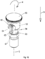
- figure 18 shows another embodiment of an actuating button 60, in which the locking lug 61 extends in the radial direction between the inner surface of the sleeve 62 and the mounting sleeve.
- a circular section was drawn in the lateral surface of the sleeve 62 in the drawing in order to make the locking lug 61 visible.
- the detent 61 is designed in the form of a pin and engages in a recess formed by a link guide 63 in the sleeve section 63 .
Landscapes
- Engineering & Computer Science (AREA)
- General Engineering & Computer Science (AREA)
- Mechanical Engineering (AREA)
- Mutual Connection Of Rods And Tubes (AREA)
- Dowels (AREA)
Abstract
Federbelasteter Rastbolzen (1) mit einer Führungshülse (30, 40), die in eine zugeordnete Bohrung in ein Maschinen- oder Möbelteil eingeschraubt ist, und einem in der Führungshülse (30, 40) axial verschiebbar gelagerten Stellzapfen (20, 20'), wobei der Stellzapfen (20, 20') in mindestens zwei Rastpositionen in der Führungshülse (30, 40) bringbar ist, der aus einer aus der Führungshülse (30, 40) axial vorstehenden Sperrstellung entgegen der Stellkraft einer Axialdruckfeder (6) in eine zurückgezogene, nicht axial aus der Führungshülse (30, 40) vorstehende Neutralstellung verstellbar ist, und der ein Verriegelungsende (2) und ein Betätigungsende (22, 22') in Verbindung mit einem Betätigungsknopf (10, 10') aufweist, wobei der Betätigungsknopf (10, 10') eine äußere Hülse (12) aufweist, mit welcher der Betätigungsknopf (10, 10') auf einem Hülsenabschnitt (33, 43) der Führungshülse (30, 40) axial verschiebbar gelagert ist, wobei der Betätigungsknopf (10, 10') eine innerseitige Rastnase (15) umfasst, die in eine korrespondierende Aussparung (39) in der Seitenwand des Hülsenabschnitts (33, 43), in der Sperrstellung rastend eingreift und den, unter Federkraft eingerückten, Betätigungsknopf (10, 10') gegenüber einer axialen Drehung um die Mittelachse (5) des Rastbolzens (1) fixiert und in der Neutralstellung die fixierte Position der Rastnase (15) aufgehoben ist und der Betätigungsknopf (10, 10') wieder um die Mittelachse (5) drehbar ist.Spring-loaded locking bolt (1) with a guide sleeve (30, 40) which is screwed into an associated bore in a machine or furniture part, and an adjusting pin (20, 20') mounted so that it can move axially in the guide sleeve (30, 40), wherein the adjusting pin (20, 20') can be brought into at least two locking positions in the guide sleeve (30, 40), which can be moved from a locking position protruding axially out of the guide sleeve (30, 40) against the adjusting force of an axial compression spring (6) into a retracted, non-locking position axially out of the guide sleeve (30, 40) protruding neutral position, and which has a locking end (2) and an actuating end (22, 22') in connection with an actuating knob (10, 10'), wherein the actuating knob (10, 10 ') has an outer sleeve (12) with which the actuating knob (10, 10') is mounted in an axially displaceable manner on a sleeve section (33, 43) of the guide sleeve (30, 40), the actuating knob (10, 10') having a internal locking lug (15) to which engages in a corresponding recess (39) in the side wall of the sleeve section (33, 43) in a latching manner in the locked position and prevents the actuating button (10, 10') engaged under spring force from rotating axially about the central axis (5). of the locking bolt (1) and in the neutral position the fixed position of the locking lug (15) is canceled and the actuating button (10, 10') can be rotated again about the central axis (5).
Description
Gegenstand der Erfindung ist ein federbelasteter Rastbolzen nach dem Oberbegriff des Patentanspruches 1.The invention relates to a spring-loaded locking bolt according to the preamble of
Ein solcher Rastbolzen ist beispielsweise in der
Dabei kann der Stellzapfen zumindest in einer axialen Endposition gegenüber der Führungshülse mit einem Rastmechanismus rastend oder mit Magnetelementen magnetisch haftend zeitweise oder dauerhaft festgelegt werden.In this case, the adjusting pin can be temporarily or permanently fixed at least in an axial end position relative to the guide sleeve with a latching mechanism or with magnet elements.
Weiterhin kann der Rastbolzen über eine selbsttätige Rückstellung verfügen und dadurch eine Grundstellung einnehmen.Furthermore, the locking bolt can have an automatic reset and thus assume a basic position.
Ob der Rastbolzen zur Betätigung bzw. zur Ver- oder Entriegelung durch Drücken oder Ziehen des Betätigungselements, beispielsweise einem Betätigungsknopf, bewegt wird, hängt vom Einbauort und der Funktionsweise des rückstellenden Elements, z. B. einer Druck- oder Zugfeder ab. Bevorzugt ist eine Axialdruckfeder vorgesehen, die den Stellzapfen des Rastbolzens in eine axiale Endposition drückt.Whether the locking bolt is moved for actuation or for locking or unlocking by pressing or pulling the actuating element, for example an actuating button, depends on the installation location and the mode of operation of the restoring element, e.g. B. from a compression or tension spring. An axial compression spring is preferably provided, which presses the adjusting pin of the locking bolt into an axial end position.
Die
Erst nach einem erneuten Ziehen des Betätigungsknopfes wird die Führungshülse außer Eingriff mit der inneren Hülse gebracht und der Betätigungsknopf kann soweit gedreht werden, bis die beiden Sechskantprofile fluchten und der Stellzapfen in axialer Richtung in die Sperrstellung bringbar ist.Only after the actuating knob is pulled again is the guide sleeve disengaged from the inner sleeve and the actuating knob can be rotated until the two hexagonal profiles are aligned and the adjusting pin can be brought into the locking position in the axial direction.
Nachteilig daran ist, dass nie genau bestimmt werden kann, in welcher Drehposition sich der um seine Längsachse drehbare Stellzapfen befindet. Dies ist jedoch bei der Verwendung eines Stellzapfens mit einer Auflaufschräge, am freien Ende des Stellzapfens, erforderlich, da die Ausrichtung der Auflaufschräge Einfluss auf die Fixierung eines Bauteils hat, in dessen Ausnehmung die Spitze des Stellzapfens in Eingriff bringbar ist oder welches von der Spitze hintergriffen ist. So kann in ausgewählten Richtungen ein selbsttätiges Ein- und/ oder Ausrasten ermöglicht werden, wohingegen andere Richtungen, in der sich Bauteil und Stellzapfen relativ zueinander bewegen, gesperrt sind. Allerdings ist eine solche Bedienung bei diesem Stand der Technik nicht möglich, weil eine richtungsabhängige Einstellung der Auflaufschräge des Stellzapfens fehlt.The disadvantage of this is that it can never be precisely determined in which rotational position the adjusting pin, which can be rotated about its longitudinal axis, is located. However, this is necessary when using an adjusting pin with a ramp at the free end of the adjusting pin, since the orientation of the ramp affects the fixing of a component in whose recess the tip of the adjusting pin can be brought into engagement or which the tip engages behind is. In this way, automatic engagement and/or disengagement can be made possible in selected directions, whereas other directions in which the component and adjusting pin move relative to one another are blocked. However, such an operation is not possible with this prior art because there is no direction-dependent adjustment of the run-up slope of the adjusting pin.
Der Erfindung liegt deshalb die Aufgabe zugrunde, einen Rastbolzen der eingangs genannten Art so weiter zu bilden, dass unter Berücksichtig einer vereinfachten Ausgestaltung eine bestimmte Ausrichtung der Auflaufschräge möglich ist, damit der Rastbolzen fehlerfrei betätigt werden kann.The invention is therefore based on the object of further developing a locking bolt of the type mentioned at the outset in such a way that, taking into account a simplified configuration, a specific orientation of the ramp is possible so that the locking bolt can be actuated without errors.
Die Aufgabe wird erfindungsgemäß durch die Merkmale des unabhängigen Patentanspruches gelöst, während vorteilhafte Ausgestaltungen und Weiterbildungen der Erfindung den Unteransprüchen entnommen werden können.The object is achieved according to the invention by the features of the independent patent claim, while advantageous configurations and developments of the invention can be found in the dependent claims.
Vorteilhaftes Merkmal ist, dass der Betätigungsknopf mindestens eine innerseitige Rastnase umfasst, die in eine korrespondierende Aussparung in der Seitenwand des Hülsenabschnitts der Führungshülse in der Sperrstellung rastend eingreift und den unter Federkraft eingerückten Betätigungsknopf gegenüber einer axialen Drehung um die Mittelachse des Rastbolzens drehfest fixiert und in der Neutralstellung die drehfeste, fixierte Position der Rastnase aufgehoben ist und der Betätigungsknopf um die Mittelachse drehbar ist.An advantageous feature is that the actuation button comprises at least one latching lug on the inside, which engages and latches into a corresponding recess in the side wall of the sleeve section of the guide sleeve in the locked position the actuating button engaged under spring force is fixed in a rotationally fixed manner relative to an axial rotation about the central axis of the locking bolt and in the neutral position the rotationally fixed, fixed position of the latching lug is canceled and the actuating button can be rotated about the central axis.
Die Rastnase ist am Innenumfang der Hülse angeordnet und erstreckt sich in radialer und axialer Richtung.The detent is arranged on the inner circumference of the sleeve and extends in the radial and axial directions.
Die vorliegende Erfindung ist jedoch nicht auf diese Ausführungsform der Rastnase beschränkt. Auch von einer Rastnase abweichende Geometrien, wie z.B. ein Raststeg, welcher in eine seitliche Rastnut in der Seitenwand des Hülsenabschnitts eingreift, wird mit der vorliegenden Erfindung beansprucht. So werden auch beispielsweise gebogene oder eckige Rastnasen beansprucht. Gegenüber der Formgebung der Rastnase weist die Aussparung stet eine komplementäre Formgebung auf.However, the present invention is not limited to this embodiment of the detent. The present invention also claims geometries that deviate from a locking lug, such as a locking web which engages in a lateral locking groove in the side wall of the sleeve section. For example, curved or angular detents are claimed. Compared to the shape of the detent, the recess always has a complementary shape.
In einer vorteilhaften Ausführungsform ist die Rastnase in Neutralstellung und bei Drehung des Betätigungsknopfs nicht mehr in Eingriff mit der Aussparung und sitzt aufgrund der wirkenden Federkraft auf der Stirnseite des Hülsenabschnitts der Führungshülse auf und ist in mindestens zwei unterschiedliche Rastpositionen der Führungshülse bringbar. Somit kann eine Rastsperre geschaffen werden die dazu dient den Betätigungsknopf in einer bestimmten gedrehten Endposition zu fixieren. Durch die Auflage auf der Stirnseite ist auch keine Änderungen der Position des Stellzapfens in axialer Richtung mehr möglich.In an advantageous embodiment, the latching lug is no longer in engagement with the recess in the neutral position and when the actuating button is turned and sits on the end face of the sleeve section of the guide sleeve due to the acting spring force and can be brought into at least two different latching positions of the guide sleeve. Thus, a locking device can be created which serves to fix the actuating button in a specific rotated end position. Due to the support on the end face, it is also no longer possible to change the position of the adjusting pin in the axial direction.
Ein nach unten offener Aufnahmeraum im Inneren des Betätigungsknopfs dient zur Aufnahme des Hülsenabschnitts der Führungshülse, wenn der Rastbolzen in die Sperrstellung überführt wird.A downwardly open receiving space inside the actuating knob is used to receive the sleeve section of the guide sleeve when the latching bolt is moved into the locked position.
Die Position des Betätigungsknopfes, bei der die Nase auf der Stirnseite des Hülsenabschnitts aufliegt, lässt sich erst durch eine Drehung des in Neutralstellung gezogenen Betätigungsknopfs erreichen.The position of the actuating button in which the lug rests on the end face of the sleeve section can only be reached by rotating the actuating button, which is pulled into the neutral position.
In einer besonders vorteilhaften Weiterbildung dieser Ausführungsform weist die Stirnseite des Hülsenabschnitts mindestens eine Rastnut zur Aufnahme der Rastnase auf. Bevorzugt sind hierbei zwei Rastnuten, in welche die Rastnase bei einer Drehung des Betätigungsknopfes einfahren kann. So gelagert kann der Rastbolzen in der erreichten Endposition zeitweise oder dauerhaft verbleiben. Eine weitere Drehung oder ein Lösen der Rastnase aus einer Rastnut kann nur durch Kraftaufwand in Drehrichtung um die Mittelachse und/oder Ziehen des Betätigungsknopfs erreicht werden.In a particularly advantageous development of this embodiment, the end face of the sleeve section has at least one latching groove for receiving the latching lug. Two latching grooves are preferred here, into which the latching lug can move when the actuating button is rotated. Stored in this way, the indexing bolt can temporarily or permanently remain in the end position it has reached. A further rotation or a release of the locking lug from a locking groove can only be achieved by applying force in the direction of rotation about the central axis and/or by pulling the actuating button.
Wird die Rastnase soweit gedreht bis sie die Aussparung in der Wandung des Hülsenabschnitts erreicht, ist die Rastnase nicht mehr in Kontakt mit der Stirnseite des Hülsenabschnitts und der Betätigungsknopf hat keinen Halt mehr auf der Stirnseite. Die Rastnase ist nun in diesem, durch die Aussparung gebildeten, Freiraum aufgenommen und bewegt sich aufgrund der Rückstellkraft der Axialdruckfeder aus der Neutralstellung entlang des Hülsenabschnitts bis die vollständige Sperrstellung erreicht ist. Durch die Bewegung wird auch der Betätigungsknopf, in dem die Rastnase angeordnet ist, wieder in Richtung des Außensechskants bewegt.If the latching lug is turned until it reaches the recess in the wall of the sleeve section, the latching lug is no longer in contact with the end face of the sleeve section and the actuating button no longer has any hold on the end face. The detent is now accommodated in this free space formed by the recess and moves due to the restoring force of the axial compression spring from the neutral position along the sleeve section until the complete blocking position is reached. As a result of the movement, the actuation button, in which the detent is arranged, is also moved back in the direction of the external hexagon.
In einer Weiterbildung dieser Ausführungsform kommt die Stirnfläche der knopfseitigen Hülse bei dieser Bewegung auf der Oberseite des Außensechskants zur Auflage, um eine weitere Bewegung in axialer Richtung zu blockieren. Die Auflage auf der Oberseite des Außensechskants bildet somit die Endposition der axialen Bewegung, bei der der Stellzapfen maximal aus der Führungshülse hervorsteht.In a further development of this embodiment, the end face of the button-side sleeve comes to rest on the upper side of the external hexagon during this movement in order to block further movement in the axial direction. The support on the upper side of the hexagon head thus forms the end position of the axial movement, in which the adjusting pin protrudes as far as possible from the guide sleeve.
In einer weiteren vorteilhaften Weiterbildung weist der Stellzapfen am Verriegelungsende einen Sperrzapfen auf, an dessen Ende sich eine Auflaufschräge befindet sowie einen an den Sperrzapfen in Richtung des Betätigungsende anschließenden und im Durchmesser radial verringerten Führungsabschnitt, der zumindest abschnittsweise von der Axialdruckfeder umgeben ist und in das Betätigungsende mündet, welches mit dem Betätigungsknopf axial feststehend in Eingriff bringbar ist.In a further advantageous development, the adjusting pin has a locking pin at the locking end, at the end of which there is a ramp and a guide section which adjoins the locking pin in the direction of the actuating end and has a radially reduced diameter, which is at least partially surrounded by the axial compression spring and which extends into the actuating end opens out, which can be brought into engagement with the operating knob in an axially fixed manner.
Eine bevorzugte Weiterbildung des Rastbolzens ist dadurch gekennzeichnet, dass die Führungshülse eine axiale Führungsbohrung aufweist, durch die der Stellzapfen geführt ist und die in Richtung des Verriegelungsende offen ist und in Richtung des Betätigungsende einen Bohrungsabschnitt aufweist, der die Führungsbohrung radial verengt, und dass sich die Führungsbohrung oberhalb des Bohrungsabschnitts wieder radial vergrößert und einen Innenraum innerhalb des Hülsenabschnitts bildet, der in Richtung des Betätigungsendes offen ist.A preferred development of the locking bolt is characterized in that the guide sleeve has an axial guide bore, through which the adjusting pin is guided and which is open in the direction of the locking end and has a bore section in the direction of the actuating end, which narrows the guide bore radially, and that the Guide bore radially enlarged again above the bore section and forms an interior space within the sleeve section which is open towards the actuating end.
Die Axialdruckfeder ist zwischen einer, gegenüber dem Führungsabschnitt radial vergrößerten Ringschulter des Sperrzapfens und einem Anschlagsteg, zu Beginn des Bohrungsabschnitts der Führungshülse, eigenspannt.The axial compression spring is internally tensioned between an annular shoulder of the locking pin, which is radially larger than the guide section, and a stop web at the start of the bore section of the guide sleeve.
In einer bevorzugten Weiterbildung weist der Betätigungsknopf in radialen Abstand zur äußeren Hülse eine innenliegende, sich in axialer Richtung erstreckende, Montagehülse auf, in der das Betätigungsende des Stellzapfens mindestens teilweise aufgenommen ist.In a preferred development, the actuating button has an inner mounting sleeve, which extends in the axial direction and is radially spaced from the outer sleeve and in which the actuating end of the adjusting pin is at least partially accommodated.
In einer besonders vorteilhaften Weiterbildung dieser Ausführungsform weist das Betätigungsende des Stellzapfens eine Profilierung zur drehfesten und kraftschlüssigen Verbindung mit der Montagehülse auf.In a particularly advantageous development of this embodiment, the actuation end of the adjusting pin has a profile for a non-rotatable and non-positive connection with the mounting sleeve.
In einer besonders vorteilhaften Weiterbildung weist die Montagehülse ein zu dem Außenprofil des Betätigungsendes korrespondierendes Innenprofil auf.In a particularly advantageous development, the mounting sleeve has an inner profile that corresponds to the outer profile of the actuation end.
In einer weiteren vorteilhaften Weiterbildung dieser Ausführungsform weist die Seitenwand der Montagehülse in Axialrichtung verlaufende Schlitze auf, die elastisch aufweitbar sind, um eine feste Aufnahme des Betätigungsendes im Inneren der Montagehülse zu gewährleisten.In a further advantageous development of this embodiment, the side wall of the mounting sleeve has slots running in the axial direction, which can be expanded elastically in order to ensure that the actuation end is firmly accommodated inside the mounting sleeve.
In einer bevorzugten Weiterbildung schließt sich an die Montagehülse eine durch den Kopf des Betätigungsknopfes verlaufende Durchführung an, durch die eine Schraube geführt ist, die in ein in Längsrichtung des Betätigungsendes eingebrachtes Gewinde, zur axialen Verstellung des federvorgespannten Stellzapfens, eingreift.In a preferred further development, the mounting sleeve is followed by a passage running through the head of the actuating knob, through which a screw is guided, which engages in a thread provided in the longitudinal direction of the actuating end, for the axial adjustment of the spring-loaded adjusting pin.
Damit ist ein Einstellen der Axialposition des Arretierstifts in der maximal ausgerückten Stellung, bei gleichbleibender rotatorischer Ausrichtung der Spitze, relativ zur Führungshülse möglich. Betätigt man die Schraube im Uhrzeigersinn, schraubt sich diese tiefer in das Gewinde im Betätigungsende. Da der Schraubenkopf gegenüber einer axialen Bewegung in der Durchführung Lagegesichert ist, verursacht der Gewindeeingriff eine Zugbewegung und der Stellzapfen wird in Richtung des Betätigungskopfs bewegt. Das Verriegelungsende wird somit in die Führungshülse eingezogen.It is thus possible to set the axial position of the locking pin in the maximum disengaged position, with the tip remaining in the same rotational alignment relative to the guide sleeve. Turning the screw clockwise will screw it deeper into the thread in the actuation end. Since the screw head is secured against axial movement in the bushing, the threaded engagement causes a pulling movement and the adjustment pin is moved towards the actuator head. The locking end is thus drawn into the guide sleeve.
Betätigt man die Schraube entgegen dem Uhrzeigersinn, wird der Stellzapfen von dem Betätigungsknopf wegbewegt und das Verriegelungsende wandert weiter aus der nach unten offenen Führungshülse heraus.If the screw is actuated anti-clockwise, the adjusting pin is moved away from the actuation button and the locking end moves further out of the guide sleeve, which is open at the bottom.
In einer bevorzugten Weiterbildung eines Rastbolzens bildet der gegenüber der Führungsbohrung radial verringerte Bohrungsabschnitt einen weiteren Anschlagsteg in Richtung des Betätigungsendes, auf dem ein in einer Ringnut des Führungsabschnitts des Sperrzapfens mindestens teilweise eingebrachter Sprengring, bei Entkopplung des Gewindes von der Schraube und axialer Bewegung des Stellzapfens, aufliegt.In a preferred development of a locking bolt, the bore section, which is radially reduced compared to the guide bore, forms a further stop web in the direction of the actuating end, on which a snap ring, which is at least partially introduced in an annular groove of the guide section of the locking pin, upon decoupling the thread from the screw and axial movement of the adjusting pin, rests.
In einer alternativen Ausgestaltung des erfindungsgemäßen Rastbolzens ist die Führungshülse mindestens zweigeteilt und besteht aus einer Steckhülse sowie einer auf der Steckhülse aufsteckbaren und drehbaren Aufnahmehülse.In an alternative embodiment of the locking bolt according to the invention, the guide sleeve is at least divided into two and consists of a socket and a rotatable receiving sleeve that can be pushed onto the socket.
In einer besonders vorteilhaften Weiterbildung dieser Ausführungsform weist die Steckhülse eine Ringnut auf, in die eine von der Aufnahmehülse nach Innen ragende Madenschraube eingreift, die beiden Hülsen gegeneinander lagesichert.In a particularly advantageous further development of this embodiment, the plug-in sleeve has an annular groove into which a grub screw protruding inwards from the receiving sleeve engages, which secures the two sleeves against one another.
Löst man die Madenschraube kann man die Aufnahmehülse relativ zur Steckhülse verdrehen. Da die Aufnahmehülse, ebenso wie bei der ersten Ausführungsform, eine Aussparung für die Aufnahme und Führung des Rastzahns des Betätigungsknopfs aufweist, kann durch eine Drehung der Aufnahmehülse auch die Drehlage geändert werden, bei der die Betätigungshülse mit dem Rastzahn in die Aussparung eingreift. Da bei der zweiten Ausführungsform die Betätigungshülse drehfest mit der Stellzapfen verbunden ist, kann somit auch die Ausrichtung der am Ende des Stellzapfens vorhandenen Auflaufschräge eingestellt werden.If you loosen the grub screw, you can rotate the receiving sleeve relative to the socket. Since the receiving sleeve, as in the first embodiment, has a recess for receiving and guiding the locking tooth of the actuating knob, the rotational position can also be changed by rotating the receiving sleeve, in which the actuating sleeve with the locking tooth in the recess engages. Since, in the second embodiment, the actuating sleeve is non-rotatably connected to the adjusting pin, the alignment of the run-up slope present at the end of the adjusting pin can also be adjusted.
Somit kann die Ausrichtung der Auflaufschräge durch ein Lösen der Madenschrauben und verdrehen der Aufnahmehülse eingestellt werden, ohne den Rastbolzen zu ziehen oder auseinander zu bauen. Eine Ausrichtung der Auflaufschräge ist somit in Sperrstellung des Rastbolzens, d.h. wenn der Stellzapfen komplette aus der Führungshülse herausragt, möglich.Thus, the orientation of the ramp can be adjusted by loosening the grub screws and turning the receiving sleeve without pulling or disassembling the locking bolt. It is therefore possible to align the ramp when the locking bolt is in the locked position, i.e. when the adjusting pin protrudes completely from the guide sleeve.
Auch andere Formen einer Verdrehsicherung als Sicherungselement werden mit der vorliegenden Erfindung beansprucht, wie beispielsweise ein Stellring, ein Sicherungsring, eine Sicherungsscheibe, Splinte oder Achshalter, welche zur Sicherung der Bauteile gegen axiales Verschieben oder Verdrehen dienen. Diese Sicherung kann form- oder kraftschlüssig erfolgen.Other forms of anti-twist protection as a securing element are also claimed with the present invention, such as an adjusting ring, a locking ring, a locking washer, cotter pins or axle holders, which serve to secure the components against axial displacement or twisting. This backup can be positive or non-positive.
Der Erfindungsgegenstand der vorliegenden Erfindung ergibt sich nicht nur aus dem Gegenstand der einzelnen Patentansprüche, sondern auch aus der Kombination der einzelnen Patentansprüche untereinander.The subject matter of the present invention results not only from the subject matter of the individual patent claims, but also from the combination of the individual patent claims with one another.
Alle in den Unterlagen, einschließlich der Zusammenfassung offenbarten Angaben und Merkmale, insbesondere die in den Zeichnungen dargestellte räumliche Ausbildung, werden als erfindungswesentlich beansprucht, soweit sie einzeln oder in Kombination gegenüber dem Stand der Technik neu sind.All information and features disclosed in the documents, including the abstract, in particular the spatial configuration shown in the drawings, are claimed to be essential to the invention insofar as they are new compared to the prior art, individually or in combination.
Soweit einzelne Gegenstände als "erfindungswesentlich" oder "wichtig" bezeichnet sind, bedeutet dies nicht, dass diese Gegenstände notwendigerweise den Gegenstand eines unabhängigen Anspruches bilden müssen. Dies wird allein durch die jeweils geltende Fassung des unabhängigen Patentanspruches bestimmt.Insofar as individual subjects are designated as "essential to the invention" or "important", this does not mean that these subjects must necessarily form the subject of an independent claim. This is determined solely by the applicable version of the independent patent claim.
Im Folgenden wird die Neuerung anhand von mehreren Ausführungswegen darstellenden Zeichnungen näher erläutert. Hierbei gehen aus den Zeichnungen und ihrer Beschreibung weitere erfindungswesentliche Merkmale und Vorteile der Neuerung hervor.In the following, the innovation is explained in more detail with reference to drawings showing several execution paths. Further features and advantages of the innovation that are essential to the invention emerge from the drawings and their description.
Es zeigen:
- Figur 1:
- ein Schnitt einer ersten Ausführungsform eines Rastbolzens gemäß der vorliegenden Erfindung. Schnitt
I-I gemäß Figur 3 ; - Figur 2:
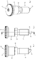
- eine Seitenansicht der in 1 veranschaulichten ersten Ausführungsform;
- Figur 3:
eine gegenüber 2 gedrehte Seitenansicht;- Figur 4:
- eine Perspektivansicht der ersten Ausführungsform;
- Figur 5:
- ein Schnitt der Führungshülse;
- Figur 6:
- eine Perspektivansicht der Führungshülse;
Figur 7;- ein Schnitt des Betätigungsknopfs;
- Figur 8:
- eine Unteransicht auf den Betätigungsknopf;
- Figur 9:
- eine Seitenansicht des Stellzapfens;
- Figur 10:
- ein Schnitt des in 9 gezeigten Stellzapfens;
- Figur 11:
- eine Explosionsansicht einer zweiten Ausführungsform eines Rastbolzens gemäß der vorliegenden Erfindung;
- Figur 12:
- ein Schnitt der zweiten Ausführungsform eines Rastbolzens gemäß der vorliegenden Erfindung;
- Figur 13:
- eine Seitenansicht der in 12 veranschaulichten zweiten Ausführungsform des Rastbolzens im gezogenen Zustand;
- Figur 14:
- eine Seitenansicht der in 12
und 13 veranschaulichten zweiten Ausführungsform eines Rastbolzens; - Figur 15:
- eine perspektivische Ansicht eines Rastbolzens mit teilweise geschnittenen Betätigungskopf nach einer dritten Ausführungsform;
- Figur 16:
- eine perspektivische Ansicht eines Rastbolzens mit teilweise geschnittenen Betätigungskopf nach einer vierten Ausführungsform;
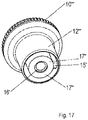
- Figur 17:
- eine perspektivische Ansicht eines Betätigungskopfs nach einer fünften Ausführungsform;
- Figur 18:
- eine perspektivische Ansicht eines Rastbolzens mit teilweise geschnittenen Betätigungskopf nach einer sechsten Ausführungsform;
- Figur 19:
- eine perspektivische Ansicht eines Rastbolzens mit te Betätigungskopf nach einer siebten Ausführungsform;
- Figure 1:
- a section of a first embodiment of a locking pin according to the present invention. Section II according to
figure 3 ; - Figure 2:
- 12 is a side view of the first embodiment illustrated in FIG. 1;
- Figure 3:
- a rotated side view compared to FIG. 2;
- Figure 4:
- a perspective view of the first embodiment;
- Figure 5:
- a cut of the guide sleeve;
- Figure 6:
- a perspective view of the guide sleeve;
- figure 7;
- a cut of the operating button;
- Figure 8:
- a bottom view of the operating knob;
- Figure 9:
- a side view of the adjusting pin;
- Figure 10:
- a section of the adjusting pin shown in FIG. 9;
- Figure 11:
- an exploded view of a second embodiment of a locking bolt according to the present invention;
- Figure 12:
- a section of the second embodiment of a locking pin according to the present invention;
- Figure 13:
- a side view of the illustrated in 12 second embodiment of the locking bolt in the pulled state;
- Figure 14:
- 12 and 13 is a side view of the second embodiment of a detent bolt illustrated in FIGS.
- Figure 15:
- a perspective view of a locking bolt with a partially cut actuating head according to a third embodiment;
- Figure 16:
- a perspective view of a locking bolt with a partially cut actuating head according to a fourth embodiment;
- Figure 17:
- a perspective view of an actuating head according to a fifth embodiment;
- Figure 18:
- a perspective view of a locking bolt with a partially sectioned actuating head according to a sixth embodiment;
- Figure 19:
- a perspective view of a locking bolt with te actuating head according to a seventh embodiment;
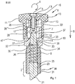
Oberhalb des Außengewindes 31 schließt sich, etwa im mittleren Bereich der Führungshülse 30, ein Außensechskant 32 an, über welchen die Führungshülse 30 in das Maschinenbauteil oder dergleichen eingeschraubt werden kann. Dieser Außensechskant ist beispielsweise in den
Nach oben hin schließt sich an diesen Außensechskant 32 ein Hülsenabschnitt 33 an, welcher einen Hohlzylinder bildet. Etwa im axialen Bereich des Außensechskantes 32 sowie des Außengewindes 31 weist die Führungshülse 30 eine abgestufte Führungsbohrung 34 auf, welche etwa im Bereich des Außensechskantes 32 einen radial nach innen abgesetzten Anschlagsteg 35 bildet.At the top, a
An diesen Anschlag 35 schließt sich zum Hülsenabschnitt 33 hin ein radial verjüngter Bohrungsabschnitt 36 an, welcher in einen radial erweiterten Innenraum 37 des Hülsenabschnittes 33 mündet.A radially tapered
Durch den Innenraum 37, dem Bohrungsabschnitt 36 und der Führungsbohrung 34 ist ein Stellzapfen 20 eingesetzt, welcher in seinem unteren Betätigungsende 22 einen radial erweiterten Sperrzapfen 23 bildet, wie dies aus
An diesen Sperrzapfen 23 schließt sich nach oben hin ein Führungsabschnitt 26 an, der im Durchmesser verringert durch den gegenüber der Führungsbohrung 34 radial verjüngten Bohrungsabschnitt 36 durchragt und sich bis in den sich wieder radial erweiterten Innenraum 37 erstreckt. Am Ende des Führungsabschnittes 26, d.h. an den dem Sperrzapfen 23 gegenüberliegendem Abschnitt, bildet der Stellzapfen 20 einen Betätigungsende 22, auf dem der Betätigungsknopf 10 montierbar ist.This locking
Wie aus
Hierzu weist der Betätigungsknopf 10 eine innere Montagehülse 17 auf, welche zur Aufnahme des Betätigungsendes 22 ein entsprechend im Durchmesser angepasstes Innenprofil 19 bildet, von welchem in
Das Betätigungsende 22 des Stellzapfens 20, welches in die sich radial verjüngt ausgebildete Montagehülse 17 eingesetzt ist, ist durch die Schraube 9, welche in das Gewinde 29 des Betätigungsende 22 eingeschraubt ist, axial feststehend fixiert ist.The actuating
Die Schraube 9 ist mittig der Oberseite des Betätigungsknopfes 10 in eine Durchführung 16 passend eingesetzt und hier durch einen kreisförmigen Auflagesteg gegenüber einer axialen Bewegung in Pfeilrichtung 8 lagegesichert.The
Eine Axialdruckfeder 6 ist auf den Führungsabschnitt 26 des Stellzapfens 20 aufsetzbar und befindet sich zusammen mit dem unteren Sperrzapfen 23 innerhalb des radial erweiterten Bereiches der Führungsbohrung 34. Mittels dieser Axialdruckfeder 6 wird der Stellzapfen 20 in seiner Sperrposition gehalten, in welcher der Sperrzapfen 23 axial nach unten aus der Führungshülse 30 vorsteht und eine Anlaufschräge 21 aufweist. Die Stellfeder 6 ist unter axialer Vorspannung angeordnet und zwischen Ringschulter 25 und Anschlagsteg 35 eingespannt.An
Aufgrund der Sperrwirkung der Rastnase 15 mit der Rastnut 41 ist diese axiale Position des Stellzapfens 20 innerhalb er Führungshülse 33 fixiert.Due to the blocking effect of the
Des Weiteren ist aus den
Gemäß den
Gleichzeitig stützt sich die Stirnfläche 14 der Hülse des Betätigungsknopfs 10 am Anschlagsteg 47 oberhalb des Außensechskants 32 axial ab.At the same time, the
Die
Wird nun der Betätigungsknopf 10 zusammen mit dem damit verschraubten Stellzapfen 20 entgegen der Pfeilrichtung 8 gezogen, so kommt die Rastnase 15 außer Eingriff mit der Rastnut 41 und kann bei Drehung des Betätigungsknopfes 10 in Pfeilrichtung 4 entlang der Stirnseite 38 des Hülsenabschnitts 33 gleiten, bis die Rastnase in den Bereich oberhalb der Aussparung 39 gelangt. Nun ist die Rastnase 15 nicht mehr in Kontakt mit der Stirnseite 38 und der Betätigungskopf 10 kann wieder in Richtung des Anschlagstegs 47 in Pfeilrichtung 8 bewegt werden. Diese Bewegung wird unterstütz durch die Rückstellkraft der Axialdruckfeder 6.If the
Die Begrenzung des vertikalen Stellweges des Stellzapfens 20 in Richtung des Pfeiles 8 kann durch die Schraube 9 eingestellt werden. Um nun den Betätigungsknopf 10 zusammen mit dem Stellzapfen 20 wieder in die in
In
Ausgehend von der Unterseite des Kopfes 11 ragt die Montagehülse 17 in den Aufnahmeraum 13. Die Montagehülse 17 weist randseitige Schlitze 18 auf, die sich in axialer Richtung erstrecken und eine elastische Aufweitung der Montagehülse bei Einführung des Betätigungsendes 22 zu ermöglichen. Im Inneren der Montagehülse 17 weist diese ein Innenprofil auf, welches an das Profil des Betätigungsendes 22 angepasst ist.Starting from the underside of the
Der Sperrzapfen 23 weist an seinem Außenumfang eine radial nach außen hin offene Nut auf, die die Markierung 24 bildet. Bei einer, unterhalb der Führungshülse 30, sichtbaren Markierung 24 ist für das Bedienungspersonal erkennbar, dass sich der gesamte Stellzapfen 20 mit seinem Sperrzapfen 23 in einer Raststellung befindet, in welcher der Sperrzapfen 23 maximal aus der Führungshülse 30 vorsteht.The locking
Am Ende des Führungsabschnitts 26, kurz vor Beginn des Betätigungsendes 22, weist der Führungsabschnitt 26 an seinem Außenumfang eine radial nach außen hin offene Ringnut 27 auf, die zur Aufnahme des Sprengrings 7 dient. Dieser Sprengring 7 ist in
Durch die erfindungsgemäße Ausgestaltung wird somit einerseits die nach unten aus der Führungshülse 30 vorstehende relative Position des Sperrzapfens 23 gegenüber dem Betätigungsknopf 10 und andererseits gleichzeitig die zurückgezogene Neutralstellung des Betätigungsknopfs 10 und damit des Stellzapfens 20 in der Führungshülse 30 durch die Schraube 9 definiert.The configuration according to the invention thus defines, on the one hand, the relative position of the locking
Löst man die Madenschraube 3, kann man die Aufnahmehülse 54 relativ zur Steckhülse 45 verdrehen. Da die Aufnahmehülse 54, ebenso wie bei der ersten Ausführungsform, eine Aussparung 39' für die Aufnahme und Führung des Rastzahns des Betätigungsknopfs 10' aufweist, kann durch eine Drehung der Aufnahmehülse 54 auch die Drehlage geändert werden, bei der die Betätigungshülse 10' mit dem Rastzahn in die Aussparung 39' eingreift.If the
Da bei der zweiten Ausführungsform die Betätigungshülse 10' drehfest mit dem Stellzapfen 20' verbunden ist, kann somit auch die Ausrichtung der am Ende des Stellzapfens 20' vorhandenen Auflaufschräge 21' eingestellt werden.Since in the second embodiment the actuating sleeve 10' is non-rotatably connected to the adjusting pin 20', the orientation of the ramp 21' present at the end of the adjusting pin 20' can also be adjusted.
Oberhalb des Außengewindes schließt sich, etwa im mittleren Bereich der Führungshülse 40, ein Außensechskant 42 an, über welchen die Führungshülse 40 feststehend in das Maschinenbauteil oder dergleichen eingeschraubt werden kann. Dieser Außensechskant ist ebenfalls in den
Ebenfalls ist ein Sechskant oberhalb des Gewindes der Führungshülse 40 vorstellen möglich, mit dem unabhängig die Führungshülse in das Maschinenbauteil eingeschraubt werden kann.It is also possible to introduce a hexagon above the thread of the
Nach oben hin schließt sich an diesen Außensechskant 42 ein Hülsenabschnitt 43 an, welcher einen Hohlzylinder bildet. Etwa im axialen Bereich des Außensechskantes 42 sowie des Außengewindes weist die Führungshülse 40 eine abgestufte Führungsbohrung 34' auf, welche etwa im Bereich des Außensechskantes 42 einen radial nach innen abgesetzten Anschlagsteg 55 bildet.At the top, a
An diesen Anschlagsteg 55 schließt sich zum Hülsenabschnitt 43 hin ein radial verjüngter Bohrungsabschnitt 36' an, welcher in einen radial erweiterten Innenraum 37' des Hülsenabschnittes 43 mündet.A radially tapered
Durch den Innenraum 37', dem Bohrungsabschnitt 36' und der Führungsbohrung 34' ist ein Stellzapfen 20' eingesetzt, welcher in seinem einen unteren Betätigungsende einen radial erweiterten Sperrzapfen 23' bildet. Dieser Sperrzapfen 23' weist einen Außendurchmesser auf, welcher dem Innendurchmesser des Bohrungsabschnitts 36' entspricht.An adjusting pin 20' is inserted through the inner space 37', the bore section 36' and the guide bore 34' and forms a radially expanded locking pin 23' in its one lower actuating end. This locking pin 23' has an outer diameter which corresponds to the inner diameter of the bore section 36'.
An diesen Sperrzapfen 23' schließt sich nach oben hin ein Führungsabschnitt 26' an, der im Durchmesser verringert durch den gegenüber der Führungsbohrung 34' radial verjüngten Bohrungsabschnitt 36' durchragt und sich bis in den sich wieder radial erweiterten Innenraum 37' erstreckt. Am Ende des Führungsabschnittes 26', d.h. an den dem Sperrzapfen 23' gegenüber liegendem Abschnitt, bildet der Stellzapfen 20' ein Betätigungsende 22', auf den der Betätigungsknopf 10' montierbar ist.This locking pin 23' is followed at the top by a guide section 26' which, with a reduced diameter, protrudes through the bore section 36', which is radially tapered relative to the guide bore 34', and extends into the interior space 37', which is again radially widened. At the end of the guide section 26', i.e. at the section opposite the locking pin 23', the adjusting pin 20' forms an operating end 22' on which the operating knob 10' can be mounted.
Wie aus
Hierzu weist der Betätigungsknopf 10' eine innere Montagehülse 57 auf, welche zur Aufnahme des Betätigungsendes 22'entsprechend angepasst ist. Die Innenseite der Montaghülse 57 ist derart ausgebildet, dass das Betätigungsende 22' des Stellzapfens 20' nach dem Einsetzen in die Montagehülse 57 sowohl eine Kraftschluss- als auch eine Formschlussverbindung bildet, so dass nach dem Aufsetzen des Betätigungsknopfes 10' auf den Stellzapfen 20' eine axial feststehende Verbindung entsteht.For this purpose, the actuating knob 10' has an inner mounting
Eine Axialdruckfeder 6' ist auf den Führungsabschnitt 26' des Stellzapfens 20' aufsetzbar und befindet sich zusammen mit dem unteren Sperrzapfen 23' innerhalb des radial erweiterten Bereiches der Führungsbohrung 34'. Mittels dieser Axialdruckfeder 6' wird der Stellzapfen 20' in seiner Sperrposition gehalten, in welcher der Sperrzapfen 23' axial nach unten aus der Führungshülse 40 vorsteht und eine Anlaufschräge 21' aufweist.An axial compression spring 6' can be placed on the guide section 26' of the adjusting pin 20' and is located together with the lower locking pin 23' within the radially expanded area of the guide bore 34'. By means of this The adjusting pin 20' is held in its locking position by the axial compression spring 6', in which the locking pin 23' protrudes axially downward out of the
In
Des Weiteren ist aus
Gemäß
Gleichzeitig stützt sich die Stirnfläche der Hülse 12' am Anschlagsteg oberhalb des Außensechskants 42 axial ab.At the same time, the end face of the
Um nun den Betätigungsknopf 10' zusammen mit dem Stellzapfen 20' wieder in die in
Die vorliegende Erfindung ist nicht ausschließlich mit einem geschlossenen Knopf realisierbar, auch sind offene Varianten durchaus möglich, wie es in der
- 1.1.
- Rastbolzendetent bolt
- 2.2.
- Verriegelungsendelocking end
- 3.3.
- Madenschraubegrub screw
- 4.4.
- Pfeilrichtungarrow direction
- 5.5.
- Mittelachsecentral axis
- 6.6.
- Axialdruckfeder 6'axial compression spring 6'
- 7.7.
- Sprengringsnap ring
- 8.8th.
- Pfeilrichtungarrow direction
- 9.9.
- Schraubescrew
- 10.10
- Betätigungsknopf 10'operating button 10'
- 11.11.
- Kopf 11'head 11'
- 12.12.
- Hülse 12'Sleeve 12'
- 13.13.
- Aufnahmeraum 13'recording room 13'
- 14.14
- Stirnfläche (von 12)Face (of 12)
- 15.15
- Rastnase, 15'detent, 15'
- 16.16
- Durchführungexecution
- 17.17
- Montagehülse 17'mounting sleeve 17'
- 18.18
- Schlitzslot
- 19.19
- Innenprofilinterior profile
- 20.20
- Stellzapfen 20'adjusting pin 20'
- 21.21
- Auflaufschräge 21'ramp 21'
- 22.22
- Betätigungsende 22'actuation end 22'
- 23.23
- Sperrzapfen 23'locking pin 23'
- 24.24
- Markierungmark
- 25.25
- Ringschulterring shoulder
- 26.26
- Führungsabschnitt 26'guide section 26'
- 27.27
- Ringnutring groove
- 28.28
- Kragencollar
- 29.29
- Gewindethread
- 30.30
- Führungshülseguide sleeve
- 31.31
- Außengewindeexternal thread
- 32.32
- Außensechskantexternal hexagon
- 33.33
- Hülsenabschnittsleeve section
- 34.34
- Führungsbohrung 34'pilot hole 34'
- 35.35
- Anschlagstegstop bar
- 36.36
- Bohrungsabschnitt 36'bore section 36'
- 37.37
- Innenraum 37'interior 37'
- 38.38
- Stirnseiteface
- 39.39
- Aussparung 39'recess 39'
- 40.40
- Führungshülseguide sleeve
- 41.41
- Rastnutlocking groove
- 42.42
- Außensechskantexternal hexagon
- 43.43
- Hülsenabschnittsleeve section
- 44.44
- Gewindebohrungthreaded hole
- 45.45
- Steckhülsereceptacle
- 46.46
- Montagebereichassembly area
- 47.47
- Anschlagstegstop bar
- 48.48
- Stirnseite 49.AussparungFace 49.Recess
- 50.50
- Rändelungknurling
- 51.51.
- Verzahnunggearing
- 52.52
- Ringnutring groove
- 53.53
- Anschlagstegstop bar
- 54.54
- Aufnahmehülsereceiving sleeve
- 55.55
- Anschlagattack
- 57.57
- MontagehülseAssembly sleeve
- 58.58
- Rastnasedetent
- 59.59
- Aussparungrecess
- 60.60
- Betätigungsknopfoperating button
- 61.61
- Rastnasedetent
- 62.62
- Hülsesleeve
- 63.63
- Hülsenabschnittsleeve section
- 64.64
- Kulissenführunglink guide
- 65.65
- Kulissebackdrop
- 66.66
- Kulissebackdrop
- 67.67
- Endbereichend area
- 68.68
- Betätigungsknopfoperating button
- 69.69
- Hülsesleeve
- 70.70
- Rastnasedetent
- 71.71
- Hülsenabschnittsleeve section
- 72.72
- Aussparungrecess
- 73.73
- Stirnseiteface
Claims (15)
Applications Claiming Priority (1)
| Application Number | Priority Date | Filing Date | Title |
|---|---|---|---|
| DE102020132928.8A DE102020132928A1 (en) | 2020-12-10 | 2020-12-10 | Spring-loaded indexing bolt |
Publications (2)
| Publication Number | Publication Date |
|---|---|
| EP4012200A1 true EP4012200A1 (en) | 2022-06-15 |
| EP4012200B1 EP4012200B1 (en) | 2023-12-27 |
Family
ID=78212035
Family Applications (1)
| Application Number | Title | Priority Date | Filing Date |
|---|---|---|---|
| EP21202818.7A Active EP4012200B1 (en) | 2020-12-10 | 2021-10-15 | Spring-loaded detent bolt |
Country Status (4)
| Country | Link |
|---|---|
| US (1) | US20220186766A1 (en) |
| EP (1) | EP4012200B1 (en) |
| CN (1) | CN114623136B (en) |
| DE (1) | DE102020132928A1 (en) |
Citations (8)
| Publication number | Priority date | Publication date | Assignee | Title |
|---|---|---|---|---|
| DE29519311U1 (en) | 1995-12-06 | 1996-03-28 | Helmut Kassner Fa | Locking bolt for fixing device parts |
| EP1236910A2 (en) * | 2001-03-02 | 2002-09-04 | Otto Ganter GmbH & Co. KG Normteilefabrik | Spring-loaded press pin |
| DE10338621A1 (en) * | 2003-08-22 | 2005-03-24 | Otto Ganter Gmbh & Co. Kg Normteilefabrik | Spring-loaded bolt, for use in machine and furniture assembly, is mounted in polygonal sleeve which interlocks with polygonal recess in outer housing attached to head |
| EP2163772A1 (en) * | 2008-09-13 | 2010-03-17 | Otto Ganter GmbH & Co. KG Normteilefabrik | Locking pin with rest lock and release button |
| US20120055302A1 (en) * | 2009-04-21 | 2012-03-08 | Makita Corporation | Structure for preventing removal of fixing tool for splitter in cutting machine |
| DE102012112610A1 (en) | 2012-12-19 | 2014-06-26 | Weber Maschinentechnik Gmbh | Notched pin used in e.g. fixture construction, has indexing mechanism with detent or magnet elements, that is magnetically attached corresponding to bolt in first axial limit position and second axial end position |
| EP3499055A1 (en) * | 2017-12-14 | 2019-06-19 | Kipp Verpachtungen e.K. | Asymmetrical locking bolt with different rotating positions |
| EP3605268A1 (en) * | 2018-08-01 | 2020-02-05 | Otto Ganter GmbH & Co. KG Normteilefabrik | Locking pin with protected latching mechanism |
Family Cites Families (24)
| Publication number | Priority date | Publication date | Assignee | Title |
|---|---|---|---|---|
| US1376122A (en) * | 1920-05-19 | 1921-04-26 | Songey Elmo | Window-fastener |
| FR1372185A (en) * | 1962-10-22 | 1964-09-11 | Aerpat Ag | Quick release assembly member |
| US4165854A (en) * | 1978-03-29 | 1979-08-28 | Cramer Industries, Inc. | Eccentric pawl for chair locking device |
| CH659293A5 (en) * | 1983-05-24 | 1987-01-15 | Meyer Fa Rudolf | Bayonet connection between two structural parts |
| US5586852A (en) * | 1993-12-28 | 1996-12-24 | Otto Ganter & Co. Kg | Spring-loaded press pin |
| DE10060412A1 (en) * | 2000-12-05 | 2002-06-06 | Bayer Ag | DELTA 1 Pyrrolines |
| US20030156923A1 (en) * | 2002-02-16 | 2003-08-21 | Winkler John M. | Indexing plunger |
| US6666636B2 (en) * | 2002-04-23 | 2003-12-23 | Illinois Tool Works, Inc. | Removable deep set drop-in anchor |
| US20070003365A1 (en) * | 2005-06-30 | 2007-01-04 | Lms-Walt Inc. | Guard for protecting a pinch point |
| US20070003361A1 (en) * | 2005-07-01 | 2007-01-04 | Shu-Mei Wang | Locking device for a telescopic tube |
| DE102007037242B4 (en) * | 2006-08-14 | 2019-05-29 | Böllhoff Verbindungstechnik GmbH | Fastening device with tolerance compensation |
| DE102008010465A1 (en) * | 2008-02-21 | 2009-09-17 | Otto Ganter Gmbh & Co. Kg Normteilefabrik | Locking bolt for keys for attachment of safety device, has key-guide rail provided in key shaft, and accommodating and guiding transversal pin for providing form-fit coupling between keys and locking pins |
| DE202008016076U1 (en) * | 2008-12-04 | 2009-02-26 | Zl Microdent-Attachment Gmbh & Co. Kg | Screw and screwing tool |
| DE202009004833U1 (en) * | 2009-05-19 | 2009-09-24 | Ebner, Johann | locking element |
| US8702046B2 (en) * | 2010-07-26 | 2014-04-22 | L&P Property Management Company | Mounting device |
| TW201248027A (en) * | 2011-05-24 | 2012-12-01 | Hanwit Prec Ind Ltd | Fixing bolt |
| DE102011118538B4 (en) * | 2011-11-15 | 2014-03-20 | Otto Ganter Gmbh & Co. Kg Normteilefabrik | Fixation of the plunger of a quick release device |
| US9452516B2 (en) * | 2014-02-10 | 2016-09-27 | Pouria Alavi | Socket for socket wrench |
| US9091293B1 (en) * | 2014-04-18 | 2015-07-28 | Hanwit Precision Industries Ltd. | Rotary fastener |
| DE202015003789U1 (en) | 2015-05-23 | 2015-07-20 | Otto Ganter Gmbh & Co. Kg Normteilefabrik | Indexing plungers |
| DE202015005678U1 (en) * | 2015-08-10 | 2016-11-11 | Dieter Ramsauer | Indexing plungers |
| CN107299931B (en) * | 2017-07-06 | 2023-07-25 | 海盐县通顺标准件厂 | Improved split assembly screw |
| CN209586902U (en) * | 2019-01-14 | 2019-11-05 | 镇江成功汽车零部件有限公司 | A kind of separation type buckle structure fixed for automobile interior exterior decorations |
| CN109915454B (en) * | 2019-04-11 | 2023-11-28 | 北京首航科学技术开发有限公司 | Quick-release lock |
-
2020
- 2020-12-10 DE DE102020132928.8A patent/DE102020132928A1/en active Pending
-
2021
- 2021-10-15 EP EP21202818.7A patent/EP4012200B1/en active Active
- 2021-10-27 CN CN202111256485.7A patent/CN114623136B/en active Active
- 2021-12-10 US US17/547,524 patent/US20220186766A1/en active Pending
Patent Citations (8)
| Publication number | Priority date | Publication date | Assignee | Title |
|---|---|---|---|---|
| DE29519311U1 (en) | 1995-12-06 | 1996-03-28 | Helmut Kassner Fa | Locking bolt for fixing device parts |
| EP1236910A2 (en) * | 2001-03-02 | 2002-09-04 | Otto Ganter GmbH & Co. KG Normteilefabrik | Spring-loaded press pin |
| DE10338621A1 (en) * | 2003-08-22 | 2005-03-24 | Otto Ganter Gmbh & Co. Kg Normteilefabrik | Spring-loaded bolt, for use in machine and furniture assembly, is mounted in polygonal sleeve which interlocks with polygonal recess in outer housing attached to head |
| EP2163772A1 (en) * | 2008-09-13 | 2010-03-17 | Otto Ganter GmbH & Co. KG Normteilefabrik | Locking pin with rest lock and release button |
| US20120055302A1 (en) * | 2009-04-21 | 2012-03-08 | Makita Corporation | Structure for preventing removal of fixing tool for splitter in cutting machine |
| DE102012112610A1 (en) | 2012-12-19 | 2014-06-26 | Weber Maschinentechnik Gmbh | Notched pin used in e.g. fixture construction, has indexing mechanism with detent or magnet elements, that is magnetically attached corresponding to bolt in first axial limit position and second axial end position |
| EP3499055A1 (en) * | 2017-12-14 | 2019-06-19 | Kipp Verpachtungen e.K. | Asymmetrical locking bolt with different rotating positions |
| EP3605268A1 (en) * | 2018-08-01 | 2020-02-05 | Otto Ganter GmbH & Co. KG Normteilefabrik | Locking pin with protected latching mechanism |
Also Published As
| Publication number | Publication date |
|---|---|
| CN114623136A (en) | 2022-06-14 |
| CN114623136B (en) | 2024-04-19 |
| DE102020132928A1 (en) | 2022-06-15 |
| EP4012200B1 (en) | 2023-12-27 |
| US20220186766A1 (en) | 2022-06-16 |
Similar Documents
| Publication | Publication Date | Title |
|---|---|---|
| EP0918655B1 (en) | Coupling device for a vehicle | |
| DE60036005T2 (en) | BARS | |
| DE10338621B4 (en) | Spring loaded locking pin | |
| DE102013202157B4 (en) | Combination padlock with disc shape | |
| EP3256089B1 (en) | Clamping claw for attaching to a slide rail of an operating table | |
| DE2830249A1 (en) | RELEASE DEVICE FOR A CLUTCH | |
| DE10008277A1 (en) | Closure device for securing panel on air-conditioning unit; has fastening element with head piece, closure shaft fitting in bearing sleeve in head piece and handle connected to front of closure shaft | |
| EP1491295A1 (en) | Locking pin for fixing a tool member to a hydraulic pressing tool | |
| EP0555633B1 (en) | Door handle fitting | |
| DE3521155C2 (en) | ||
| DE60038654T2 (en) | Clamping bracket for support and connection elements | |
| EP0754827A2 (en) | Device for releasable and non-sliding of a handle on a bearing element, especially for door handles or window handles | |
| EP2034109B1 (en) | Rosette with a safety device | |
| EP4012200B1 (en) | Spring-loaded detent bolt | |
| DE102016215806B4 (en) | Backrest arrangement for a motor vehicle and motor vehicle | |
| EP2034110B1 (en) | Rosette with a securing device | |
| EP0663498A1 (en) | Cylinder lock | |
| EP3282058B1 (en) | Device for fixing a sanitary component, in particular a fixing frame for a toilet or urinal actuating plate | |
| EP0215295A1 (en) | Coupling for a detachable connection between a head and a handle of a dental handpiece | |
| DE102004028585B4 (en) | Fastener for attaching a container to a vehicle | |
| AT509140B1 (en) | FIXING DEVICE FOR A DRILL HEAD | |
| EP0640735A1 (en) | Door lock, especially for locking of refrigerators | |
| EP1111164B1 (en) | Fixing device for a square spindle | |
| EP3276107B1 (en) | Window handle fitting | |
| EP2155998B1 (en) | Driving rod assembly, and method for mounting a driving rod assembly |
Legal Events
| Date | Code | Title | Description |
|---|---|---|---|
| PUAI | Public reference made under article 153(3) epc to a published international application that has entered the european phase |
Free format text: ORIGINAL CODE: 0009012 |
|
| STAA | Information on the status of an ep patent application or granted ep patent |
Free format text: STATUS: THE APPLICATION HAS BEEN PUBLISHED |
|
| AK | Designated contracting states |
Kind code of ref document: A1 Designated state(s): AL AT BE BG CH CY CZ DE DK EE ES FI FR GB GR HR HU IE IS IT LI LT LU LV MC MK MT NL NO PL PT RO RS SE SI SK SM TR |
|
| STAA | Information on the status of an ep patent application or granted ep patent |
Free format text: STATUS: REQUEST FOR EXAMINATION WAS MADE |
|
| 17P | Request for examination filed |
Effective date: 20220826 |
|
| RBV | Designated contracting states (corrected) |
Designated state(s): AL AT BE BG CH CY CZ DE DK EE ES FI FR GB GR HR HU IE IS IT LI LT LU LV MC MK MT NL NO PL PT RO RS SE SI SK SM TR |
|
| GRAP | Despatch of communication of intention to grant a patent |
Free format text: ORIGINAL CODE: EPIDOSNIGR1 |
|
| STAA | Information on the status of an ep patent application or granted ep patent |
Free format text: STATUS: GRANT OF PATENT IS INTENDED |
|
| RIC1 | Information provided on ipc code assigned before grant |
Ipc: F16B 39/10 20060101ALN20230913BHEP Ipc: F16B 21/18 20060101ALN20230913BHEP Ipc: F16B 19/02 20060101ALN20230913BHEP Ipc: F16B 19/10 20060101AFI20230913BHEP |
|
| INTG | Intention to grant announced |
Effective date: 20230926 |
|
| GRAS | Grant fee paid |
Free format text: ORIGINAL CODE: EPIDOSNIGR3 |
|
| GRAA | (expected) grant |
Free format text: ORIGINAL CODE: 0009210 |
|
| STAA | Information on the status of an ep patent application or granted ep patent |
Free format text: STATUS: THE PATENT HAS BEEN GRANTED |
|
| AK | Designated contracting states |
Kind code of ref document: B1 Designated state(s): AL AT BE BG CH CY CZ DE DK EE ES FI FR GB GR HR HU IE IS IT LI LT LU LV MC MK MT NL NO PL PT RO RS SE SI SK SM TR |
|
| REG | Reference to a national code |
Ref country code: GB Ref legal event code: FG4D Free format text: NOT ENGLISH |
|
| REG | Reference to a national code |
Ref country code: CH Ref legal event code: EP |
|
| REG | Reference to a national code |
Ref country code: DE Ref legal event code: R096 Ref document number: 502021002276 Country of ref document: DE |
|
| REG | Reference to a national code |
Ref country code: IE Ref legal event code: FG4D Free format text: LANGUAGE OF EP DOCUMENT: GERMAN |
|
| PG25 | Lapsed in a contracting state [announced via postgrant information from national office to epo] |
Ref country code: GR Free format text: LAPSE BECAUSE OF FAILURE TO SUBMIT A TRANSLATION OF THE DESCRIPTION OR TO PAY THE FEE WITHIN THE PRESCRIBED TIME-LIMIT Effective date: 20240328 |
|
| REG | Reference to a national code |
Ref country code: LT Ref legal event code: MG9D |
|
| PG25 | Lapsed in a contracting state [announced via postgrant information from national office to epo] |
Ref country code: LT Free format text: LAPSE BECAUSE OF FAILURE TO SUBMIT A TRANSLATION OF THE DESCRIPTION OR TO PAY THE FEE WITHIN THE PRESCRIBED TIME-LIMIT Effective date: 20231227 |
|
| PG25 | Lapsed in a contracting state [announced via postgrant information from national office to epo] |
Ref country code: LT Free format text: LAPSE BECAUSE OF FAILURE TO SUBMIT A TRANSLATION OF THE DESCRIPTION OR TO PAY THE FEE WITHIN THE PRESCRIBED TIME-LIMIT Effective date: 20231227 Ref country code: GR Free format text: LAPSE BECAUSE OF FAILURE TO SUBMIT A TRANSLATION OF THE DESCRIPTION OR TO PAY THE FEE WITHIN THE PRESCRIBED TIME-LIMIT Effective date: 20240328 Ref country code: FI Free format text: LAPSE BECAUSE OF FAILURE TO SUBMIT A TRANSLATION OF THE DESCRIPTION OR TO PAY THE FEE WITHIN THE PRESCRIBED TIME-LIMIT Effective date: 20231227 Ref country code: BG Free format text: LAPSE BECAUSE OF FAILURE TO SUBMIT A TRANSLATION OF THE DESCRIPTION OR TO PAY THE FEE WITHIN THE PRESCRIBED TIME-LIMIT Effective date: 20240327 |
|
| REG | Reference to a national code |
Ref country code: NL Ref legal event code: MP Effective date: 20231227 |