EP4012185A2 - Kompressor mit variabler frequenz mit adaptiver heizleistungssteuerung und betriebsverfahren dafür - Google Patents
Kompressor mit variabler frequenz mit adaptiver heizleistungssteuerung und betriebsverfahren dafür Download PDFInfo
- Publication number
- EP4012185A2 EP4012185A2 EP21214347.3A EP21214347A EP4012185A2 EP 4012185 A2 EP4012185 A2 EP 4012185A2 EP 21214347 A EP21214347 A EP 21214347A EP 4012185 A2 EP4012185 A2 EP 4012185A2
- Authority
- EP
- European Patent Office
- Prior art keywords
- winding
- stator
- heating power
- rotor
- current
- Prior art date
- Legal status (The legal status is an assumption and is not a legal conclusion. Google has not performed a legal analysis and makes no representation as to the accuracy of the status listed.)
- Pending
Links
Images

Classifications
-
- H—ELECTRICITY
- H02—GENERATION; CONVERSION OR DISTRIBUTION OF ELECTRIC POWER
- H02P—CONTROL OR REGULATION OF ELECTRIC MOTORS, ELECTRIC GENERATORS OR DYNAMO-ELECTRIC CONVERTERS; CONTROLLING TRANSFORMERS, REACTORS OR CHOKE COILS
- H02P29/00—Arrangements for regulating or controlling electric motors, appropriate for both AC and DC motors
- H02P29/60—Controlling or determining the temperature of the motor or of the drive
- H02P29/64—Controlling or determining the temperature of the winding
-
- F—MECHANICAL ENGINEERING; LIGHTING; HEATING; WEAPONS; BLASTING
- F04—POSITIVE - DISPLACEMENT MACHINES FOR LIQUIDS; PUMPS FOR LIQUIDS OR ELASTIC FLUIDS
- F04C—ROTARY-PISTON, OR OSCILLATING-PISTON, POSITIVE-DISPLACEMENT MACHINES FOR LIQUIDS; ROTARY-PISTON, OR OSCILLATING-PISTON, POSITIVE-DISPLACEMENT PUMPS
- F04C23/00—Combinations of two or more pumps, each being of rotary-piston or oscillating-piston type, specially adapted for elastic fluids; Pumping installations specially adapted for elastic fluids; Multi-stage pumps specially adapted for elastic fluids
- F04C23/02—Pumps characterised by combination with, or adaptation to, specific driving engines or motors
-
- F—MECHANICAL ENGINEERING; LIGHTING; HEATING; WEAPONS; BLASTING
- F04—POSITIVE - DISPLACEMENT MACHINES FOR LIQUIDS; PUMPS FOR LIQUIDS OR ELASTIC FLUIDS
- F04C—ROTARY-PISTON, OR OSCILLATING-PISTON, POSITIVE-DISPLACEMENT MACHINES FOR LIQUIDS; ROTARY-PISTON, OR OSCILLATING-PISTON, POSITIVE-DISPLACEMENT PUMPS
- F04C29/00—Component parts, details or accessories of pumps or pumping installations, not provided for in groups F04C18/00 - F04C28/00
- F04C29/0042—Driving elements, brakes, couplings, transmissions specially adapted for pumps
- F04C29/0085—Prime movers
-
- F—MECHANICAL ENGINEERING; LIGHTING; HEATING; WEAPONS; BLASTING
- F04—POSITIVE - DISPLACEMENT MACHINES FOR LIQUIDS; PUMPS FOR LIQUIDS OR ELASTIC FLUIDS
- F04B—POSITIVE-DISPLACEMENT MACHINES FOR LIQUIDS; PUMPS
- F04B35/00—Piston pumps specially adapted for elastic fluids and characterised by the driving means to their working members, or by combination with, or adaptation to, specific driving engines or motors, not otherwise provided for
- F04B35/04—Piston pumps specially adapted for elastic fluids and characterised by the driving means to their working members, or by combination with, or adaptation to, specific driving engines or motors, not otherwise provided for the means being electric
-
- F—MECHANICAL ENGINEERING; LIGHTING; HEATING; WEAPONS; BLASTING
- F04—POSITIVE - DISPLACEMENT MACHINES FOR LIQUIDS; PUMPS FOR LIQUIDS OR ELASTIC FLUIDS
- F04B—POSITIVE-DISPLACEMENT MACHINES FOR LIQUIDS; PUMPS
- F04B39/00—Component parts, details, or accessories, of pumps or pumping systems specially adapted for elastic fluids, not otherwise provided for in, or of interest apart from, groups F04B25/00 - F04B37/00
- F04B39/06—Cooling; Heating; Prevention of freezing
-
- F—MECHANICAL ENGINEERING; LIGHTING; HEATING; WEAPONS; BLASTING
- F04—POSITIVE - DISPLACEMENT MACHINES FOR LIQUIDS; PUMPS FOR LIQUIDS OR ELASTIC FLUIDS
- F04B—POSITIVE-DISPLACEMENT MACHINES FOR LIQUIDS; PUMPS
- F04B49/00—Control, e.g. of pump delivery, or pump pressure of, or safety measures for, machines, pumps, or pumping installations, not otherwise provided for, or of interest apart from, groups F04B1/00 - F04B47/00
- F04B49/06—Control using electricity
-
- F—MECHANICAL ENGINEERING; LIGHTING; HEATING; WEAPONS; BLASTING
- F04—POSITIVE - DISPLACEMENT MACHINES FOR LIQUIDS; PUMPS FOR LIQUIDS OR ELASTIC FLUIDS
- F04C—ROTARY-PISTON, OR OSCILLATING-PISTON, POSITIVE-DISPLACEMENT MACHINES FOR LIQUIDS; ROTARY-PISTON, OR OSCILLATING-PISTON, POSITIVE-DISPLACEMENT PUMPS
- F04C28/00—Control of, monitoring of, or safety arrangements for, pumps or pumping installations specially adapted for elastic fluids
- F04C28/08—Control of, monitoring of, or safety arrangements for, pumps or pumping installations specially adapted for elastic fluids characterised by varying the rotational speed
-
- F—MECHANICAL ENGINEERING; LIGHTING; HEATING; WEAPONS; BLASTING
- F04—POSITIVE - DISPLACEMENT MACHINES FOR LIQUIDS; PUMPS FOR LIQUIDS OR ELASTIC FLUIDS
- F04C—ROTARY-PISTON, OR OSCILLATING-PISTON, POSITIVE-DISPLACEMENT MACHINES FOR LIQUIDS; ROTARY-PISTON, OR OSCILLATING-PISTON, POSITIVE-DISPLACEMENT PUMPS
- F04C28/00—Control of, monitoring of, or safety arrangements for, pumps or pumping installations specially adapted for elastic fluids
- F04C28/24—Control of, monitoring of, or safety arrangements for, pumps or pumping installations specially adapted for elastic fluids characterised by using valves controlling pressure or flow rate, e.g. discharge valves or unloading valves
-
- F—MECHANICAL ENGINEERING; LIGHTING; HEATING; WEAPONS; BLASTING
- F04—POSITIVE - DISPLACEMENT MACHINES FOR LIQUIDS; PUMPS FOR LIQUIDS OR ELASTIC FLUIDS
- F04C—ROTARY-PISTON, OR OSCILLATING-PISTON, POSITIVE-DISPLACEMENT MACHINES FOR LIQUIDS; ROTARY-PISTON, OR OSCILLATING-PISTON, POSITIVE-DISPLACEMENT PUMPS
- F04C29/00—Component parts, details or accessories of pumps or pumping installations, not provided for in groups F04C18/00 - F04C28/00
- F04C29/02—Lubrication; Lubricant separation
-
- F—MECHANICAL ENGINEERING; LIGHTING; HEATING; WEAPONS; BLASTING
- F04—POSITIVE - DISPLACEMENT MACHINES FOR LIQUIDS; PUMPS FOR LIQUIDS OR ELASTIC FLUIDS
- F04C—ROTARY-PISTON, OR OSCILLATING-PISTON, POSITIVE-DISPLACEMENT MACHINES FOR LIQUIDS; ROTARY-PISTON, OR OSCILLATING-PISTON, POSITIVE-DISPLACEMENT PUMPS
- F04C29/00—Component parts, details or accessories of pumps or pumping installations, not provided for in groups F04C18/00 - F04C28/00
- F04C29/04—Heating; Cooling; Heat insulation
-
- H—ELECTRICITY
- H02—GENERATION; CONVERSION OR DISTRIBUTION OF ELECTRIC POWER
- H02P—CONTROL OR REGULATION OF ELECTRIC MOTORS, ELECTRIC GENERATORS OR DYNAMO-ELECTRIC CONVERTERS; CONTROLLING TRANSFORMERS, REACTORS OR CHOKE COILS
- H02P29/00—Arrangements for regulating or controlling electric motors, appropriate for both AC and DC motors
- H02P29/60—Controlling or determining the temperature of the motor or of the drive
-
- F—MECHANICAL ENGINEERING; LIGHTING; HEATING; WEAPONS; BLASTING
- F04—POSITIVE - DISPLACEMENT MACHINES FOR LIQUIDS; PUMPS FOR LIQUIDS OR ELASTIC FLUIDS
- F04B—POSITIVE-DISPLACEMENT MACHINES FOR LIQUIDS; PUMPS
- F04B2203/00—Motor parameters
- F04B2203/02—Motor parameters of rotating electric motors
- F04B2203/0202—Voltage
-
- F—MECHANICAL ENGINEERING; LIGHTING; HEATING; WEAPONS; BLASTING
- F04—POSITIVE - DISPLACEMENT MACHINES FOR LIQUIDS; PUMPS FOR LIQUIDS OR ELASTIC FLUIDS
- F04B—POSITIVE-DISPLACEMENT MACHINES FOR LIQUIDS; PUMPS
- F04B2203/00—Motor parameters
- F04B2203/02—Motor parameters of rotating electric motors
- F04B2203/0205—Temperature
-
- F—MECHANICAL ENGINEERING; LIGHTING; HEATING; WEAPONS; BLASTING
- F04—POSITIVE - DISPLACEMENT MACHINES FOR LIQUIDS; PUMPS FOR LIQUIDS OR ELASTIC FLUIDS
- F04C—ROTARY-PISTON, OR OSCILLATING-PISTON, POSITIVE-DISPLACEMENT MACHINES FOR LIQUIDS; ROTARY-PISTON, OR OSCILLATING-PISTON, POSITIVE-DISPLACEMENT PUMPS
- F04C18/00—Rotary-piston pumps specially adapted for elastic fluids
- F04C18/02—Rotary-piston pumps specially adapted for elastic fluids of arcuate-engagement type, i.e. with circular translatory movement of co-operating members, each member having the same number of teeth or tooth-equivalents
- F04C18/0207—Rotary-piston pumps specially adapted for elastic fluids of arcuate-engagement type, i.e. with circular translatory movement of co-operating members, each member having the same number of teeth or tooth-equivalents both members having co-operating elements in spiral form
-
- F—MECHANICAL ENGINEERING; LIGHTING; HEATING; WEAPONS; BLASTING
- F04—POSITIVE - DISPLACEMENT MACHINES FOR LIQUIDS; PUMPS FOR LIQUIDS OR ELASTIC FLUIDS
- F04C—ROTARY-PISTON, OR OSCILLATING-PISTON, POSITIVE-DISPLACEMENT MACHINES FOR LIQUIDS; ROTARY-PISTON, OR OSCILLATING-PISTON, POSITIVE-DISPLACEMENT PUMPS
- F04C18/00—Rotary-piston pumps specially adapted for elastic fluids
- F04C18/30—Rotary-piston pumps specially adapted for elastic fluids having the characteristics covered by two or more of groups F04C18/02, F04C18/08, F04C18/22, F04C18/24, F04C18/48, or having the characteristics covered by one of these groups together with some other type of movement between co-operating members
- F04C18/34—Rotary-piston pumps specially adapted for elastic fluids having the characteristics covered by two or more of groups F04C18/02, F04C18/08, F04C18/22, F04C18/24, F04C18/48, or having the characteristics covered by one of these groups together with some other type of movement between co-operating members having the movement defined in group F04C18/08 or F04C18/22 and relative reciprocation between the co-operating members
- F04C18/356—Rotary-piston pumps specially adapted for elastic fluids having the characteristics covered by two or more of groups F04C18/02, F04C18/08, F04C18/22, F04C18/24, F04C18/48, or having the characteristics covered by one of these groups together with some other type of movement between co-operating members having the movement defined in group F04C18/08 or F04C18/22 and relative reciprocation between the co-operating members with vanes reciprocating with respect to the outer member
Definitions
- the present disclosure relates generally to the field of compressors, in particular, to a variable-frequency compressor with adaptive heating power control and a method for operating the same.
- a frequency converter of a variable-frequency compressor In order to control the temperature difference between an oil sump temperature of a compressor and an ambient temperature of the compressor, and to ensure effective oil dilution, a frequency converter of a variable-frequency compressor will provide a function of crankcase heating.
- the frequency converter injects a current into a stator coil to generate heat, for the purpose of evaporating liquid refrigerant and preventing excessive dilution of oil.
- a crankcase heating current parameter is built into the frequency converter of the compressor, and by adjusting this parameter, the current injected into the stator of the compressor can be adjusted, and the heating power of the crankcase can thereby be adjusted.
- the injection of a controllable current into the stator of the compressor cannot produce a controllable heating power.
- the frequency converter will inject a current into each phase according to present rotor position information, and different rotor positions will have different phase current combinations even if the amplitude of the phase current is always a same setting value. Thus, an uncertain heating amount will be generated by this function.
- the present disclosure is at least partly to provide a variable-frequency compressor with adaptive heating power control and a method for operating same.
- a variable-frequency compressor including: a compression unit, for compressing a medium entering the variable-frequency compressor; a motor, including a stator and a rotor, for driving the compression unit; and a controller, configured to adaptively control a heating power of a winding of the stator according to information of the variable-frequency compressor.
- the controller may be configured to: control the heating power of the winding of the stator according to a position of the rotor.
- the controller may be configured to: control the heating power of the winding of the stator according to a phase resistance of the winding of the stator.
- the controller may be configured to: control the heating power of the winding of the stator according to a phase resistance of the winding of the stator and a position of the rotor.
- the controller may be configured to detect the position of the rotor and adjust amplitude of a current injected into the winding of the stator according to the position of the rotor, such that the heating power of the winding is a desired heating power.
- the controller may be configured to forcibly position the rotor if the rotor position is adjustable, such that amplitude of a current injected into the winding of the stator causes the heating power of the winding to be a desired heating power.
- the controller may be configured to forcibly position the rotor in a predetermined position and inject a current into the winding of the stator according to a heating current parameter corresponding to the predetermined position, such that the heating power of the winding is a desired heating power.
- the controller may be configured to forcibly position the rotor in a position that causes a current flowing through a winding at one phase in the stator to be substantially zero.
- the controller may be configured to: detect a current flowing through windings of two phases to which a DC voltage has been applied; calculate the phase resistance of the winding of the stator of the compressor according to the DC voltage and the current; determine a temperature of the winding of the stator according to the phase resistance; inject a current into the winding of the stator according to the difference between the determined temperature and a predetermined temperature, such that the heating power of the winding of the stator is a desired heating power.
- the controller may be configured to: determine the temperature of the winding of the stator according to the phase resistance, with reference to a table of correspondence between phase resistances and temperatures that is pre-stored in a frequency converter of the variable-frequency compressor.
- the controller may be configured to: detect a position of the rotor before injecting the current into the winding of the stator and inject the current into the winding of the stator according to the position of the rotor and the difference between the determined temperature and the predetermined temperature.
- the controller may be configured to: forcibly position the rotor in a predetermined position before injecting the current into the winding of the stator, and inject the current into the winding of the stator according to the predetermined position and the difference between the determined temperature and the predetermined temperature.
- variable-frequency compressor includes: a compression unit, for compressing a medium entering the variable-frequency compressor; an electric motor, comprising a stator and a rotor, for driving the compression unit; and a controller.
- the controller adaptively controls a heating power of a winding of the stator according to the information of the variable-frequency compressor.
- the information of the variable-frequency compressor may include position information of the rotor, and the controller may control the heating power of the winding of the stator according to the position information of the rotor.
- the information of the variable-frequency compressor may include a phase resistance of the winding of the stator, and the controller may control the heating power of the winding of the stator according to the phase resistance of the winding of the stator.
- the controller may control the heating power of the winding of the stator according to a phase resistance of the winding of the stator and a position of the rotor.
- the step of controlling the heating power of the winding of the stator according to a position of the rotor may include: detecting the position of the rotor, and adjusting the amplitude of a current injected into the winding of the stator according to the position of the rotor, such that the heating power of the winding is a desired heating power.
- the step of controlling the heating power of the winding of the stator according to a position of the rotor may include: forcibly positioning the rotor if the rotor position is adjustable, such that the amplitude of a current injected into the winding of the stator causes the heating power of the winding to be a desired heating power.
- the step of forcibly positioning the rotor may include: forcibly positioning the rotor in a predetermined position, and injecting a current into the winding of the stator according to a heating current parameter corresponding to the predetermined position, such that the heating power of the winding is a desired heating power.
- the step of forcibly positioning the rotor in a predetermined position may include: forcibly positioning the rotor in a position that causes a current flowing through the winding of one phase in the stator to be substantially zero.
- the step of controlling the heating power of the winding of the stator according to a phase resistance of the winding of the stator may include: detecting a current flowing through the windings of two phases to which a DC voltage has been applied; calculating the phase resistance of the winding of the stator of the compressor according to the DC voltage and the current; determining a temperature of the winding of the stator according to the phase resistance; and injecting a current into the winding of the stator according to the difference between the determined temperature and a predetermined temperature, such that the heating power of the winding of the stator is a desired heating power.
- the step of determining a temperature of the winding of the stator according to the phase resistance may include: determining the temperature of the winding of the stator according to the phase resistance, with reference to a table of correspondence between phase resistance and temperature that is pre-stored in a frequency converter of the variable-frequency compressor.
- the method may further include: detecting a position of the rotor before injecting the current into the winding of the stator, and injecting the current into the winding of the stator according to the position of the rotor and the difference between said temperature and the predetermined temperature.
- the method may further include: forcibly positioning the rotor in a predetermined position before injecting the current into the winding of the stator, and injecting the current into the winding of the stator according to the predetermined position and the difference between said temperature and the predetermined temperature.
- Embodiments of the present invention does not rely on a crankcase heating parameter alone to inject a current into the stator winding, but also takes into account information relating to the variable-frequency compressor such as rotor position and/or stator winding phase resistance in order to inject the current, thereby achieving adaptive control of crankcase heating and satisfying heating power requirements in different situations and different time periods.
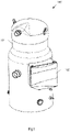
- Fig. 1 is a schematic diagram showing a compressor according to an embodiment of the present disclosure.
- the compressor 100 may include a shell 101.
- the shell 101 may be made of a hard material such as steel, etc., and has a space formed in the interior thereof for the purpose of accommodating components of the compressor 100 (not visible in Fig. 1 due to being accommodated in the shell 101), and may include a channel for a working medium flow through the compressor 100.
- the compressor componenets may comprise various components, for example a compression mechanism for compressing the working medium that enters it (e.g. the static scroll and orbiting scroll of a scroll compressor, etc.), an actuation mechanism for driving the motion of the compression mechanism to compress the working medium (e.g. an electric motor assembly, etc.), various sensors for monitoring the operating state of the compressor, and so on.
- the electric motor may include a stator and a rotor.
- the stator may include a stator winding. When the electric motor is operating, an alternating current
- AC can flow into the stator winding, thereby generating a rotating magnetic field to enable the rotor to rotate.
- the rotor may include a rotor winding.
- the rotor can cut the magnetic field of the stator, which generates an induced EMF and current, and the rotor can further driven to rotate by a force caused by the rotating magnetic field.
- the electric motor may for example be a three-phase AC electric motor.
- the compressor 100 may further include an electrical box 102.
- the electrical box 102 may be mounted on a surface of the shell 101, and used to accommodate at least a portion of electrical components of the compressor 100, for example a control component of the compressor 100 such as a controller or microcontroller, a storage component, a power supply, etc.
- Program code may be stored in the storage component, for execution by the control component in order to control the operation of the compressor 100.
- Mechanical parts of the compressor 100 such as bearings and a piston require lubrication by lubricating oil. These lubricating oils can accumulate in an oil sump at the bottom of the compressor.
- the rotation of the compressor drives a shaft to rotate; the lowermost end of the shaft is immersed in the oil sump, and a hollow inclined hole may be provided in the shaft. Oil is sucked up by centrifugal suction of rotation, delivered to each area that requires lubrication, such as the piston. Inside the piston, the oil is discharged from the compressor together with refrigerant, finally returning together with the refrigerant back into the oil sump.
- the compressor 100 may provide a crankcase heating function, in order to control the temperature difference between the oil sump temperature and the ambient temperature, as well as to evaporate liquid refrigerant and thereby prevent excessive dilution of the oil.
- the compressor 100 may be a variable-frequency compressor, and may therefore include a frequency converter (disposed in the electrical box 102 for example).
- the frequency converter can inject current into the winding of the stator, in order to realize this crankcase heating function.
- the frequency converter can control a heating power by controlling the current injected into the stator winding according to a crankcase heating parameter.
- the injection of a controllable current does not mean the ouput of controllable heating power because the frequency converter will inject current into the winding of each phase (e.g. phases U, V and W in a three-phase scenario) according to the rotor position information at that moment.
- a three-phase scenario is described as an example for introduction convenience. However, the present disclosure is not limited to this.
- the normal to the rotor is substantially in line with the direction of the winding of one phase in the stator (phase V in this example).
- the current flowing through this phase can be substantially zero.
- Substantially all of the current Iu ( 20 A) injected from phase U flows through phase W.
- the scenario (a) in Fig. 2 shows the scenario with the minimum heating power
- the scenario (b) in Fig. 2 shows the scenario with the maximum heating power.
- the heating function may be started when the compressor stops rotating, i.e., when the rotor stops running, but the position at which the rotor stops can be random.
- the actual heating power may still be different at different heating occasions.
- the heating power can be controlled according to the rotor position. For example, current is not injected into a stator winding solely according to the heating current parameter; the amplitude of the current injected into the stator winding can be adjusted according to rotor position in order to have a desired power (e.g., to make the heating power constant on every occasion).
- the rotor position is adjustable (even if the compressor has stopped rotating)
- the rotor can be forcibly positioned (parked) in order to adjust the rotor position, such that the rotor position is the same on every occasion when the heating function is performed.
- the heating power can thus be a desired power obtained according to the injected current (e.g., the injected current can be constant on every occasion).
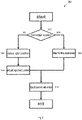
- Fig. 3 is a flow chart showing a method for adaptive control of heating power according to an embodiment of the present disclosure.
- the method 300 may include, in operation 302, determining whether the rotor can rotate when the compressor has stopped rotating.
- the amplitude of the injected current can be adjusted according to the present position of the rotor.
- the position of the rotor can be detected.
- the position of the rotor can be detected according to a built-in sensor in the compressor or by other method such as by using the salient pole effect in the motor.
- the distribution of current in the windings of different phases can be determined according to the detected rotor position, and the current that needs to be injected in order to achieve the desired power can thereby be determined.
- current can be injected into the stator windings based on the injected current determined, in order to achieve the desired power. For example, based on the injected current determined, the heating current parameter may be adjusted so as to inject a suitable current into the stator windings.
- the desired heating power is lower. For example, only 25 degrees Celsius is needed, and a heating power of 60 W may be required considering the temperature before heating.
- the current that need be injected can be determined as 20 A.
- the heating current parameter is adjusted so that the injected current is 20 A.
- the detected rotor position is between Fig. 2(a) and Fig. 2(b) , and the injected current required is then less than 20 A if a heating power of 60 W is needed.
- the heating current parameter is adjusted so that the heating power achieved by the injected current is 60 W. In this way, the injection of current according to the rotor position is realized, in order to achieve the desired heating power.
- the rotor can be forcibly positioned in operation 308 in order to adjust the rotor position.
- the rotor can be adjusted to a fixed position (relative to the stator), which can be predetermined, and this predetermined position corresponds to a predetermined heating current parameter.
- the above information and an algorithm for forcible positioning may be all stored in the frequency converter, and executed by the frequency converter.
- the rotor can be adjusted to the position shown in Fig. 2 (b) , i.e., such that the current in the winding of one phase can be substantially zero (as stated above, in this situation, the same injected current can achieve a larger heating power).
- current may be injected into the stator windings, for example, a current of a preset value may be injected.
- the desired heating power is higher. Accordingly, 45 degrees Celsius may be needed, and a heating power of 80 W may be required considering the temperature before heating.
- the rotor can be forcibly positioned in the position shown in Fig. 2(b) , in which the power added is the maximum.
- the heating current parameter is adjusted so that the injected current is 20 A.
- a current of 20 A is then injected into the stator.
- the desired heating power can likewise be achieved.
- the above is merely an example.
- the rotor may be positioned in any position, as long as the heating current parameter is determined in that position and the injected current can then be adjusted to achieve the desired heating power.
- expected heating powers may be different. For example, in the hot summer, the desired heating power may be relatively low; and in the cold winter, the desired heating power may be relatively high.
- the heating power is controllable; or by forcible positioning of the rotor, heating power can still be controllable when current is injected at a fixed position.
- the heating power is controllable and the heating function of the crankcase can be used more effectively, and the uncontrollable change of the heating power between high and low can be avoided, thus avoiding a situation where the heating power cannot be increased when a high power is required for heating and where the heating pwoer is too high when a low power is needed for heating.
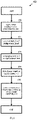
- Fig. 4 is a flow chart showing a method for adaptive control of heating power according to another embodiment of the present disclosure.
- the method 400 may include operations 402 - 410.
- a DC voltage (e.g., 5% - 20% of the rated voltage of the motor) is applied to the windings of any two phases in the compressor stator.
- phase resistance of the windings in the compressor stator is calculated.
- the value of the phase resistance of the stator windings is directly related to the present ambient temperature in the vicinity of the compressor, and the correspondence relation therebetween may be stored in the frequency converter in advance.
- the present ambient temperature is looked up in a resistance-temperature correspondence table that is pre-stored in the frequency converter.
- the current injected into the stator windings is adaptively controlled, to ensure that the heating power would be the desired heating power.
- the preset heating current parameter corresponds to a preset (or desired) temperature of the crankcase; the current injected into the stator windings can thus be controlled according to the temperature difference between the present ambient temperature and the preset temperature corresponding to the preset heating current parameter.
- the injected current is controlled to maximize the heating power; if the temperature difference is less than 3°, the injected current is controlled to minimize the heating power.
- the heating power required when three phases of currents are injected into the compressor and two of the three phases have equal currents, the heating power required is at its minimum; when two phases of currents are injected into the compressor, the heating power required is at its maximum.
- the heating power produced by any other mode of current injection lies between the minimum and the maximum, wherein the maximum power and minimum power differ by 25%.
- Operations 402 - 410 in Fig. 4 can be performed iteratively, to achieve the desired heating power by multiple times of adjustment.
- operations 402 - 410 may be performed once, so as to achieve the desired heating power directly from the present heating power.
- the rotor can be positioned in the position of Fig. 2(b) ; in this case, the injection of current into the stator according to the heating current parameter can achieve a greater heating power.
- the rotor can be gradually positioned in the position of Fig. 2(a) , at which the minimum heating power can be achieved by injecting the same current.
- the heating current parameter is adjusted according to the rotor position and the temperature difference so as to adjust the injected current, and a lower heating power can be used for heating.
Landscapes
- Engineering & Computer Science (AREA)
- Mechanical Engineering (AREA)
- General Engineering & Computer Science (AREA)
- Power Engineering (AREA)
- Physics & Mathematics (AREA)
- Fluid Mechanics (AREA)
- Control Of Positive-Displacement Pumps (AREA)
- Compressor (AREA)
- Control Of Ac Motors In General (AREA)
Applications Claiming Priority (1)
| Application Number | Priority Date | Filing Date | Title |
|---|---|---|---|
| CN202011469533.6A CN114623081B (zh) | 2020-12-14 | 2020-12-14 | 自适应控制加热功率的变频压缩机及其操作方法 |
Publications (2)
| Publication Number | Publication Date |
|---|---|
| EP4012185A2 true EP4012185A2 (de) | 2022-06-15 |
| EP4012185A3 EP4012185A3 (de) | 2022-07-13 |
Family
ID=78851187
Family Applications (1)
| Application Number | Title | Priority Date | Filing Date |
|---|---|---|---|
| EP21214347.3A Pending EP4012185A3 (de) | 2020-12-14 | 2021-12-14 | Kompressor mit variabler frequenz mit adaptiver heizleistungssteuerung und betriebsverfahren dafür |
Country Status (3)
| Country | Link |
|---|---|
| US (1) | US11955915B2 (de) |
| EP (1) | EP4012185A3 (de) |
| CN (1) | CN114623081B (de) |
Families Citing this family (2)
| Publication number | Priority date | Publication date | Assignee | Title |
|---|---|---|---|---|
| CN117606130B (zh) * | 2023-11-02 | 2025-10-28 | Tcl空调器(中山)有限公司 | 压缩机的控制方法、电路、空调器和存储介质 |
| CN118889943A (zh) * | 2024-09-30 | 2024-11-01 | 珠海格力电器股份有限公司 | 压缩机三相绕组的加热方法及装置 |
Family Cites Families (18)
| Publication number | Priority date | Publication date | Assignee | Title |
|---|---|---|---|---|
| US5362222A (en) | 1993-08-31 | 1994-11-08 | Cincinnati Milacron Inc. | Injection molding machine having a vector controlled AC drive system |
| US7242166B2 (en) | 2002-07-31 | 2007-07-10 | Sydkraft Ab | Electric machine |
| JP4428017B2 (ja) | 2002-12-09 | 2010-03-10 | パナソニック株式会社 | インバータ装置 |
| US6874329B2 (en) * | 2003-05-30 | 2005-04-05 | Carrier Corporation | Refrigerant cooled variable frequency drive and method for using same |
| US7202626B2 (en) * | 2005-05-06 | 2007-04-10 | York International Corporation | Variable speed drive for a chiller system with a switched reluctance motor |
| AU2007282582B2 (en) | 2006-08-11 | 2010-10-28 | Daikin Industries, Ltd. | Refrigeration apparatus |
| US20100064703A1 (en) | 2006-12-29 | 2010-03-18 | Carrier Corporation | Standby variable frequency compressor drive |
| US8601828B2 (en) * | 2009-04-29 | 2013-12-10 | Bristol Compressors International, Inc. | Capacity control systems and methods for a compressor |
| US8734125B2 (en) | 2009-09-24 | 2014-05-27 | Emerson Climate Technologies, Inc. | Crankcase heater systems and methods for variable speed compressors |
| US8800521B2 (en) | 2011-12-20 | 2014-08-12 | GM Global Technology Operations LLC | Electric vehicle fluid preheater |
| CN102761300B (zh) * | 2012-02-20 | 2013-03-13 | 珠海格力电器股份有限公司 | 永磁同步电机的绕组预热及其启动方法 |
| US9181939B2 (en) | 2012-11-16 | 2015-11-10 | Emerson Climate Technologies, Inc. | Compressor crankcase heating control systems and methods |
| US9353738B2 (en) | 2013-09-19 | 2016-05-31 | Emerson Climate Technologies, Inc. | Compressor crankcase heating control systems and methods |
| CN106160615A (zh) * | 2016-08-03 | 2016-11-23 | 珠海格力节能环保制冷技术研究中心有限公司 | 电机控制系统、压缩机及电机加热启动方法 |
| US11277086B2 (en) | 2017-09-22 | 2022-03-15 | Janislav SEGA | Radially symmetric three-phase optimized power control PCB layout |
| CN108768225B (zh) | 2018-05-29 | 2020-12-29 | 广东威灵电机制造有限公司 | 转子的预定位拖动方法、系统以及同步电机控制系统 |
| CN111376795A (zh) * | 2018-12-29 | 2020-07-07 | 比亚迪汽车工业有限公司 | 用于加热电动汽车的电池的控制方法、系统及电动汽车 |
| CN110557075A (zh) * | 2019-10-08 | 2019-12-10 | 珠海格力电器股份有限公司 | 电机转矩的确定方法及装置、电机控制系统 |
-
2020
- 2020-12-14 CN CN202011469533.6A patent/CN114623081B/zh active Active
-
2021
- 2021-12-14 EP EP21214347.3A patent/EP4012185A3/de active Pending
- 2021-12-14 US US17/550,249 patent/US11955915B2/en active Active
Also Published As
| Publication number | Publication date |
|---|---|
| US11955915B2 (en) | 2024-04-09 |
| CN114623081B (zh) | 2024-12-20 |
| US20220186730A1 (en) | 2022-06-16 |
| EP4012185A3 (de) | 2022-07-13 |
| CN114623081A (zh) | 2022-06-14 |
Similar Documents
| Publication | Publication Date | Title |
|---|---|---|
| JP6858199B2 (ja) | 電動ポンプ装置 | |
| CN101932833B (zh) | 集成压缩机马达和制冷剂/油加热器的装置和方法 | |
| CA2805787C (en) | Method and apparatus for control of a synchronous permanent magnet motor, particularly over a long cable in a well | |
| EP4012185A2 (de) | Kompressor mit variabler frequenz mit adaptiver heizleistungssteuerung und betriebsverfahren dafür | |
| CA2680529A1 (en) | Open-loop method for controlling power | |
| CN102498643A (zh) | 电驱动系统 | |
| JP6010071B2 (ja) | モータ制御装置及び冷凍・空調装置 | |
| KR100301499B1 (ko) | 인버터냉장고압축기의윤활모드설정방법 | |
| KR101770425B1 (ko) | 냉장고 및 냉장고의 제어방법 | |
| JP7115360B2 (ja) | 電動圧縮機 | |
| KR20180101369A (ko) | 스타델타 전환을 하는 진공 펌프 구동장치 | |
| KR102171448B1 (ko) | 냉장고의 인버터 압축기 및 냉장고 인버터 압축기의 제어 방법 | |
| JP2018174602A (ja) | 圧縮機および圧縮機を搭載した機器 | |
| CN111980951B (zh) | 驱动控制装置和马达装置 | |
| JP2007535283A (ja) | 誘導モータ制御システム | |
| JP2009153355A (ja) | 同期モータの制御方法および制御装置 | |
| JP2006223014A (ja) | モータ駆動装置 | |
| JP2007330012A (ja) | 冷蔵庫 | |
| JP2006042429A (ja) | ブラシレスdcモータの駆動方法及びその装置 | |
| JP2007143240A (ja) | モータの駆動装置 | |
| HK1152364B (en) | Integral compressor motor and refrigerant/oil heater apparatus and method | |
| KR20100075065A (ko) | Bldc 모터의 속도 제어방법 |
Legal Events
| Date | Code | Title | Description |
|---|---|---|---|
| PUAI | Public reference made under article 153(3) epc to a published international application that has entered the european phase |
Free format text: ORIGINAL CODE: 0009012 |
|
| STAA | Information on the status of an ep patent application or granted ep patent |
Free format text: STATUS: THE APPLICATION HAS BEEN PUBLISHED |
|
| PUAL | Search report despatched |
Free format text: ORIGINAL CODE: 0009013 |
|
| AK | Designated contracting states |
Kind code of ref document: A2 Designated state(s): AL AT BE BG CH CY CZ DE DK EE ES FI FR GB GR HR HU IE IS IT LI LT LU LV MC MK MT NL NO PL PT RO RS SE SI SK SM TR |
|
| AK | Designated contracting states |
Kind code of ref document: A3 Designated state(s): AL AT BE BG CH CY CZ DE DK EE ES FI FR GB GR HR HU IE IS IT LI LT LU LV MC MK MT NL NO PL PT RO RS SE SI SK SM TR |
|
| RIC1 | Information provided on ipc code assigned before grant |
Ipc: F04C 18/02 20060101ALN20220603BHEP Ipc: F04C 29/04 20060101AFI20220603BHEP |
|
| STAA | Information on the status of an ep patent application or granted ep patent |
Free format text: STATUS: REQUEST FOR EXAMINATION WAS MADE |
|
| 17P | Request for examination filed |
Effective date: 20230102 |
|
| RBV | Designated contracting states (corrected) |
Designated state(s): AL AT BE BG CH CY CZ DE DK EE ES FI FR GB GR HR HU IE IS IT LI LT LU LV MC MK MT NL NO PL PT RO RS SE SI SK SM TR |
|
| P01 | Opt-out of the competence of the unified patent court (upc) registered |
Effective date: 20230713 |
|
| STAA | Information on the status of an ep patent application or granted ep patent |
Free format text: STATUS: EXAMINATION IS IN PROGRESS |
|
| 17Q | First examination report despatched |
Effective date: 20231214 |
|
| GRAP | Despatch of communication of intention to grant a patent |
Free format text: ORIGINAL CODE: EPIDOSNIGR1 |
|
| STAA | Information on the status of an ep patent application or granted ep patent |
Free format text: STATUS: GRANT OF PATENT IS INTENDED |
|
| RIC1 | Information provided on ipc code assigned before grant |
Ipc: F04C 29/04 20060101AFI20250813BHEP Ipc: F04C 18/02 20060101ALN20250813BHEP |
|
| INTG | Intention to grant announced |
Effective date: 20250912 |
|
| STAA | Information on the status of an ep patent application or granted ep patent |
Free format text: STATUS: THE APPLICATION IS DEEMED TO BE WITHDRAWN |