EP4012145A1 - Schiebetürvorrichtung - Google Patents
Schiebetürvorrichtung Download PDFInfo
- Publication number
- EP4012145A1 EP4012145A1 EP20852514.7A EP20852514A EP4012145A1 EP 4012145 A1 EP4012145 A1 EP 4012145A1 EP 20852514 A EP20852514 A EP 20852514A EP 4012145 A1 EP4012145 A1 EP 4012145A1
- Authority
- EP
- European Patent Office
- Prior art keywords
- sliding door
- pull
- rail
- support shaft
- straight portion
- Prior art date
- Legal status (The legal status is an assumption and is not a legal conclusion. Google has not performed a legal analysis and makes no representation as to the accuracy of the status listed.)
- Granted
Links
Images


Classifications
-
- E—FIXED CONSTRUCTIONS
- E05—LOCKS; KEYS; WINDOW OR DOOR FITTINGS; SAFES
- E05D—HINGES OR SUSPENSION DEVICES FOR DOORS, WINDOWS OR WINGS
- E05D15/00—Suspension arrangements for wings
- E05D15/06—Suspension arrangements for wings for wings sliding horizontally more or less in their own plane
- E05D15/10—Suspension arrangements for wings for wings sliding horizontally more or less in their own plane movable out of one plane into a second parallel plane
- E05D15/1042—Suspension arrangements for wings for wings sliding horizontally more or less in their own plane movable out of one plane into a second parallel plane with transversely moving carriage
-
- E—FIXED CONSTRUCTIONS
- E05—LOCKS; KEYS; WINDOW OR DOOR FITTINGS; SAFES
- E05D—HINGES OR SUSPENSION DEVICES FOR DOORS, WINDOWS OR WINGS
- E05D15/00—Suspension arrangements for wings
- E05D15/06—Suspension arrangements for wings for wings sliding horizontally more or less in their own plane
- E05D15/10—Suspension arrangements for wings for wings sliding horizontally more or less in their own plane movable out of one plane into a second parallel plane
-
- E—FIXED CONSTRUCTIONS
- E05—LOCKS; KEYS; WINDOW OR DOOR FITTINGS; SAFES
- E05F—DEVICES FOR MOVING WINGS INTO OPEN OR CLOSED POSITION; CHECKS FOR WINGS; WING FITTINGS NOT OTHERWISE PROVIDED FOR, CONCERNED WITH THE FUNCTIONING OF THE WING
- E05F1/00—Closers or openers for wings, not otherwise provided for in this subclass
- E05F1/08—Closers or openers for wings, not otherwise provided for in this subclass spring-actuated, e.g. for horizontally sliding wings
- E05F1/16—Closers or openers for wings, not otherwise provided for in this subclass spring-actuated, e.g. for horizontally sliding wings for sliding wings
-
- E—FIXED CONSTRUCTIONS
- E05—LOCKS; KEYS; WINDOW OR DOOR FITTINGS; SAFES
- E05F—DEVICES FOR MOVING WINGS INTO OPEN OR CLOSED POSITION; CHECKS FOR WINGS; WING FITTINGS NOT OTHERWISE PROVIDED FOR, CONCERNED WITH THE FUNCTIONING OF THE WING
- E05F5/00—Braking devices, e.g. checks; Stops; Buffers
- E05F5/003—Braking devices, e.g. checks; Stops; Buffers for sliding wings
-
- E—FIXED CONSTRUCTIONS
- E05—LOCKS; KEYS; WINDOW OR DOOR FITTINGS; SAFES
- E05D—HINGES OR SUSPENSION DEVICES FOR DOORS, WINDOWS OR WINGS
- E05D15/00—Suspension arrangements for wings
- E05D15/06—Suspension arrangements for wings for wings sliding horizontally more or less in their own plane
- E05D15/10—Suspension arrangements for wings for wings sliding horizontally more or less in their own plane movable out of one plane into a second parallel plane
- E05D15/1042—Suspension arrangements for wings for wings sliding horizontally more or less in their own plane movable out of one plane into a second parallel plane with transversely moving carriage
- E05D2015/1055—Suspension arrangements for wings for wings sliding horizontally more or less in their own plane movable out of one plane into a second parallel plane with transversely moving carriage with slanted or curved track sections or cams
-
- E—FIXED CONSTRUCTIONS
- E05—LOCKS; KEYS; WINDOW OR DOOR FITTINGS; SAFES
- E05Y—INDEXING SCHEME ASSOCIATED WITH SUBCLASSES E05D AND E05F, RELATING TO CONSTRUCTION ELEMENTS, ELECTRIC CONTROL, POWER SUPPLY, POWER SIGNAL OR TRANSMISSION, USER INTERFACES, MOUNTING OR COUPLING, DETAILS, ACCESSORIES, AUXILIARY OPERATIONS NOT OTHERWISE PROVIDED FOR, APPLICATION THEREOF
- E05Y2201/00—Constructional elements; Accessories therefor
- E05Y2201/60—Suspension or transmission members; Accessories therefor
- E05Y2201/622—Suspension or transmission members elements
- E05Y2201/624—Arms
-
- E—FIXED CONSTRUCTIONS
- E05—LOCKS; KEYS; WINDOW OR DOOR FITTINGS; SAFES
- E05Y—INDEXING SCHEME ASSOCIATED WITH SUBCLASSES E05D AND E05F, RELATING TO CONSTRUCTION ELEMENTS, ELECTRIC CONTROL, POWER SUPPLY, POWER SIGNAL OR TRANSMISSION, USER INTERFACES, MOUNTING OR COUPLING, DETAILS, ACCESSORIES, AUXILIARY OPERATIONS NOT OTHERWISE PROVIDED FOR, APPLICATION THEREOF
- E05Y2201/00—Constructional elements; Accessories therefor
- E05Y2201/60—Suspension or transmission members; Accessories therefor
- E05Y2201/622—Suspension or transmission members elements
- E05Y2201/64—Carriers
-
- E—FIXED CONSTRUCTIONS
- E05—LOCKS; KEYS; WINDOW OR DOOR FITTINGS; SAFES
- E05Y—INDEXING SCHEME ASSOCIATED WITH SUBCLASSES E05D AND E05F, RELATING TO CONSTRUCTION ELEMENTS, ELECTRIC CONTROL, POWER SUPPLY, POWER SIGNAL OR TRANSMISSION, USER INTERFACES, MOUNTING OR COUPLING, DETAILS, ACCESSORIES, AUXILIARY OPERATIONS NOT OTHERWISE PROVIDED FOR, APPLICATION THEREOF
- E05Y2201/00—Constructional elements; Accessories therefor
- E05Y2201/60—Suspension or transmission members; Accessories therefor
- E05Y2201/622—Suspension or transmission members elements
- E05Y2201/684—Rails; Tracks
-
- E—FIXED CONSTRUCTIONS
- E05—LOCKS; KEYS; WINDOW OR DOOR FITTINGS; SAFES
- E05Y—INDEXING SCHEME ASSOCIATED WITH SUBCLASSES E05D AND E05F, RELATING TO CONSTRUCTION ELEMENTS, ELECTRIC CONTROL, POWER SUPPLY, POWER SIGNAL OR TRANSMISSION, USER INTERFACES, MOUNTING OR COUPLING, DETAILS, ACCESSORIES, AUXILIARY OPERATIONS NOT OTHERWISE PROVIDED FOR, APPLICATION THEREOF
- E05Y2201/00—Constructional elements; Accessories therefor
- E05Y2201/60—Suspension or transmission members; Accessories therefor
- E05Y2201/622—Suspension or transmission members elements
- E05Y2201/686—Rods, links
-
- E—FIXED CONSTRUCTIONS
- E05—LOCKS; KEYS; WINDOW OR DOOR FITTINGS; SAFES
- E05Y—INDEXING SCHEME ASSOCIATED WITH SUBCLASSES E05D AND E05F, RELATING TO CONSTRUCTION ELEMENTS, ELECTRIC CONTROL, POWER SUPPLY, POWER SIGNAL OR TRANSMISSION, USER INTERFACES, MOUNTING OR COUPLING, DETAILS, ACCESSORIES, AUXILIARY OPERATIONS NOT OTHERWISE PROVIDED FOR, APPLICATION THEREOF
- E05Y2600/00—Mounting or coupling arrangements for elements provided for in this subclass
- E05Y2600/10—Adjustable
- E05Y2600/12—Adjustable by manual operation
-
- E—FIXED CONSTRUCTIONS
- E05—LOCKS; KEYS; WINDOW OR DOOR FITTINGS; SAFES
- E05Y—INDEXING SCHEME ASSOCIATED WITH SUBCLASSES E05D AND E05F, RELATING TO CONSTRUCTION ELEMENTS, ELECTRIC CONTROL, POWER SUPPLY, POWER SIGNAL OR TRANSMISSION, USER INTERFACES, MOUNTING OR COUPLING, DETAILS, ACCESSORIES, AUXILIARY OPERATIONS NOT OTHERWISE PROVIDED FOR, APPLICATION THEREOF
- E05Y2800/00—Details, accessories and auxiliary operations not otherwise provided for
- E05Y2800/20—Combinations of elements
- E05Y2800/205—Combinations of elements forming a unit
-
- E—FIXED CONSTRUCTIONS
- E05—LOCKS; KEYS; WINDOW OR DOOR FITTINGS; SAFES
- E05Y—INDEXING SCHEME ASSOCIATED WITH SUBCLASSES E05D AND E05F, RELATING TO CONSTRUCTION ELEMENTS, ELECTRIC CONTROL, POWER SUPPLY, POWER SIGNAL OR TRANSMISSION, USER INTERFACES, MOUNTING OR COUPLING, DETAILS, ACCESSORIES, AUXILIARY OPERATIONS NOT OTHERWISE PROVIDED FOR, APPLICATION THEREOF
- E05Y2800/00—Details, accessories and auxiliary operations not otherwise provided for
- E05Y2800/20—Combinations of elements
- E05Y2800/23—Combinations of elements of elements of different categories
- E05Y2800/24—Combinations of elements of elements of different categories of springs and brakes
-
- E—FIXED CONSTRUCTIONS
- E05—LOCKS; KEYS; WINDOW OR DOOR FITTINGS; SAFES
- E05Y—INDEXING SCHEME ASSOCIATED WITH SUBCLASSES E05D AND E05F, RELATING TO CONSTRUCTION ELEMENTS, ELECTRIC CONTROL, POWER SUPPLY, POWER SIGNAL OR TRANSMISSION, USER INTERFACES, MOUNTING OR COUPLING, DETAILS, ACCESSORIES, AUXILIARY OPERATIONS NOT OTHERWISE PROVIDED FOR, APPLICATION THEREOF
- E05Y2800/00—Details, accessories and auxiliary operations not otherwise provided for
- E05Y2800/20—Combinations of elements
- E05Y2800/244—Combinations of elements arranged in serial relationship
-
- E—FIXED CONSTRUCTIONS
- E05—LOCKS; KEYS; WINDOW OR DOOR FITTINGS; SAFES
- E05Y—INDEXING SCHEME ASSOCIATED WITH SUBCLASSES E05D AND E05F, RELATING TO CONSTRUCTION ELEMENTS, ELECTRIC CONTROL, POWER SUPPLY, POWER SIGNAL OR TRANSMISSION, USER INTERFACES, MOUNTING OR COUPLING, DETAILS, ACCESSORIES, AUXILIARY OPERATIONS NOT OTHERWISE PROVIDED FOR, APPLICATION THEREOF
- E05Y2900/00—Application of doors, windows, wings or fittings thereof
- E05Y2900/10—Application of doors, windows, wings or fittings thereof for buildings or parts thereof
- E05Y2900/13—Type of wing
- E05Y2900/132—Doors
Definitions
- the present invention relates to a sliding door device for moving a sliding door between a closed position for closing an opening and an opened position for allowing the sliding door to face a wall or the like adjacent to the opening.
- This sliding door device includes a rail for guiding a support shaft attached to the sliding door.
- the rail includes a straight portion for linearly guiding the support shaft and an inclined portion which is inclined with respect to the straight portion and obliquely guides the support shaft.
- the sliding door moves between the closed position for closing the opening and the opened position for allowing the sliding door to face the wall adjacent to the opening.
- this sliding door device since the sliding door and a wall surface become flat when the sliding door is closed, it is possible to produce a clear and smart space. Further, when the sliding door is opened, it is possible to form a large opening.
- the sliding door device is provided with a pull-in device for pulling the sliding door to the closed position.
- the pull-in device is disposed on a rail side, that is, on the inclined portion of the rail to capture a roller traveling body which has moved from the straight portion to the inclined portion and pull the support shaft attached to the roller traveling body to the closed position.
- Patent Document 1 JP 2008-285942A
- a sliding door device which can move a support shaft attached to a sliding door along an inclined portion of a rail by using a pull-in device which can linearly move along a straight portion of the rail or a trigger which can linearly move along the straight portion of the rail.
- one aspect of the present invention relates to a sliding door device comprising a rail having a straight portion for linearly guiding a support shaft attached to a sliding door and an inclined portion which is inclined with respect to the straight portion and obliquely guides the support shaft; a pull-in device which can capture a trigger provided on the rail and linearly move along the straight portion of the rail when the sliding door is closed; and a pull-in force transmission part which is coupled to the pull-in device and moves the support shaft along the inclined portion according to linear movement of the pull-in device.
- a sliding door device comprising a rail having a straight portion for linearly guiding a support shaft attached to a sliding door and an inclined portion which is inclined with respect to the straight portion and obliquely guides the support shaft; a trigger which can be captured by a pull-in device and linearly move along the straight portion of the rail when the sliding door is closed; and a pull-in force transmission part which is coupled to the trigger and moves the support shaft along the inclined portion according to linear movement of the trigger.
- the support shaft attached to the sliding door along the inclined portion of the rail by using the pull-in device which can linearly move along the straight portion of the rail.
- sliding door devices according to embodiments of the present invention will be described based on the accompanying drawings.
- the sliding door device of the present invention may be embodied in various forms and is not limited to the embodiments described in the specification.
- the embodiments are provided with intention of sufficiently providing the disclosure of the specification for allowing a person having ordinary skill in the art to sufficiently understand the scope of the invention.
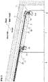
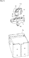
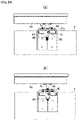
- Fig. 1 and Fig. 2 show a sliding door device 1 according to a first embodiment of the present invention (an upper surface side perspective view of the sliding door 2).
- Fig. 1 shows a state that the sliding door 2 is in a closed position.
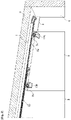
- Fig. 2 shows a state that the sliding door 2 is opened from the closed position to a predetermined position in an opening direction.
- the following description uses a direction when the sliding door is viewed from the front side, that is a door head and door tail direction and a depth direction shown in Fig. 1 for explaining a configuration of the sliding door 1.
- the reference number "3" refers to a frame
- the reference number "4" refers to an opening
- the reference number "5" refers to a wall
- the reference numbers "6a”, “6b” respectively refer to rails
- the reference numbers "7a”, “7b” respectively refer to support shafts.
- the sliding door 2 can move between the closed position for closing the opening 4 (see Fig. 1 ) and an opened position for allowing the sliding door 2 to face the wall 5 adjacent to the opening 4.
- the sliding door 2 can move from a predetermined position shown in Fig. 2 to the opened position located in the door tail direction in Fig. 2 .
- a blind plate 8 for hiding the rails is provided on an upper portion of the opening 4 of the frame 4.
- the rails 6a, 6b include the door head side rail 6a disposed on the door head side of the frame 3 and the door tail side rail 6b disposed on the door tail side of the frame 3.
- the rail 6a includes a straight portion 11 and an inclined portion 12 connected to an end portion of the straight portion 11 and inclined with respect to the straight portion 11.
- the rail 6b also includes a straight portion 11 and an inclined portion connected to an end portion of the straight portion 11 and inclined with respect to the straight portion 11.
- the rail 6a is disposed more to the back side and the door head side than the rail 6b.
- the straight portion 11 of the rail 6a and the straight portion 11 of the rail 6b are parallel to each other.
- the support shafts 7a, 7b include the door head side support shaft 7a which can move on the rail 6a and the door tail side support shaft 7b which can move on the rail 6b.
- the support shaft 7a is supported by a roller traveling body 21a which can travel on the rail 6a (see Fig. 9 ).
- the support shaft 7b is supported by a roller traveling body 21b which can travel on the rail 6b (see Fig. 9 ).
- the support shaft 7a is attached to the door head side of the sliding door 2 through a bracket 13a.
- the support shaft 7b is attached to the door tail side of the sliding door 2 through a bracket 13b.
- a length of the bracket 13a in the depth direction is longer than a length of the bracket 13b in the depth direction.
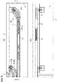
- Fig. 3 shows a detailed view of the rail 6a.
- the straight portion 11 of the rail 6a is formed in a cylindrical shape having a substantially C-shaped cross-section.
- a groove 11a extending in the lengthwise direction is formed in a lower portion of the straight portion 11.
- Rollers 16 of a pull-in device 15 travel on both sides of the groove 11a and rollers 22 of a roller traveling body 21a (see Fig. 5 ) also travel.
- an anti-vibration roller 17 of the pull-in device 15 travels inside the groove 11a and an anti-vibration roller 23 of the roller traveling body 21a (see Fig. 5 ) also travels.
- the inclined portion 12 is connected to the straight portion 11 of the rail 6a.
- the inclined portion 12 is also formed so as to have a substantially C-shaped cross-section.
- a flange 12a is formed on an upper portion of the inclined portion 12.
- a curved groove 12b is formed on a lower portion of the inclined portion 12.
- This groove 12b includes an arcuate groove 12b1 leading to the groove 11a of the straight portion 11 and a straight groove 12b2 inclined with respect to the groove 11a.
- an entire portion of the groove 12b may be formed in an arcuate groove.
- the rollers 22 of the roller traveling body 21a travel on both sides of the groove 12b.
- the anti-vibration roller 23 of the roller traveling body 21a travels inside the groove 12b.
- the rail 6b (see Fig. 1 ) has the substantially same configuration as the rail 6a, the same reference numbers are attached to components of the rail 6b and the description for the rail 6b will be omitted.
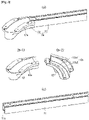
- Fig. 4 shows the rail 6a and the pull-in device 15 and Fig. 5 shows the pull-in device 15.
- the pull-in device 15 is disposed only on the rail 6a and not disposed on the rail 6b (see Fig. 9(a) ). Note that the pull-in device 15 may be disposed only on the rail 6b or the pull-in device 15 may be disposed on both of the rail 6a and the rail 6b.
- the reference number "18" refers to a trigger provided on the rail 6a.
- the trigger 18 is fastened to the rail 6a or the frame 3 by a screw or the like not shown in the drawings.
- the pull-in device 15 captures the trigger 18 and linearly moves along the straight portion 11 of the rail 6a.
- a moving direction of the pull-in device 15 and a transmission direction of pull-in force of the pull-in device 15 are indicated by an arrow A.
- the pull-in device 15 moves to the closed position shown in Fig. 4 .
- the pull-in force transmission part 20 includes the roller traveling body 21a and an arm 19 rotatably coupled to the roller traveling body 21a and the pull-in device 15.
- the arm 19 is constituted of one link.
- one end portion of the arm 19 is coupled to an end portion of the pull-in device 15 so as to be capable of rotating around a vertical shaft 26.
- another end portion of the arm 19 is coupled to the roller traveling body 21a so as to be capable of rotating around a vertical shaft 25.
- Fig. 7 to Fig. 9 show operation diagrams of the sliding door device 1 when the sliding door 2 is closed.
- the pull-in device 15 moves along the straight portion 11 of the rail 6a together with the sliding door 2.
- Fig. 7 shows a state before the pull-in device 15 captures the trigger 18.
- the pull-in device 15 when the pull-in device 15 captures a shaft portion 18a of the trigger 18, the pull-in device 15 generates the pull-in force in the direction of the arrow A and thus linearly moves in the direction of the arrow A.
- the pull-in force of the pull-in device 15 is transmitted to the roller traveling body 21a through the arm 19.
- the roller traveling body 21a moves in a direction of an arrow B along the inclined portion 12 of the rail 6a.
- the roller traveling body 21b According to the movement of the roller traveling body 21a in the direction of the arrow B, the roller traveling body 21b also moves. Since the support shafts 7a, 7b (see Fig. 1 ) are respectively attached to the roller traveling bodies 21a, 21b, the support shafts 7a, 7b move along the inclined portions 12. Therefore, it becomes possible to obliquely pull the sliding door 2 in the direction of the arrow B.
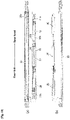
- Fig. 10 is an exploded view of the pull-in device 15.
- the pull-in device 15 has a base configuration including a base 30, a catcher 31a which can relatively slide with respect to the base 30 and a spring 32a disposed between the base 30 and the catcher 31a.
- the catcher 31a captures the trigger 18, the catcher 31a rotates to release engagement between the catcher 31a and the curved groove 30a of the base 30 and thus the base 30 moves to the door head direction in the drawing due to spring force of the spring 32a. Movement of the base 30 is braked by a first linear damper 33 and a second linear damper 34.
- two pairs of catchers 31a, 31b and springs 32a, 32b are provided so as to generate the pull-in force not only when the sliding door 2 is closed but also when the sliding door 2 is opened.
- one pair of the catcher 31a and the spring 32a may be provided so as to generate the pull-in force only when the sliding door 2 is closed.
- a first slider assembly 35 and a second slider assembly 36 are slidably provided on the base 30.
- a damper assembly 37 is slidably provided between the first slider assembly 35 and the second slider assembly 36.
- a cover 39 (see Fig. 5 ) is attached to the base 30.
- a groove 39a for receiving the shaft portion 18a of the trigger 18 is formed on the cover 39.
- Fig. 11 shows exploded views of the first slider assembly 35, the second slider assembly 36 and the damper assembly 37.
- the first slider assembly 35 includes a slider body 41, the catcher 31a, a pusher 43 and a malfunction prevention cam 44.
- the catcher 31a engages with the curved groove 30a of the base 30, and thereby a standby position of the catcher 31a is maintained.
- the pusher 43 pushes the catcher 31a so as to hold the catcher 31a in the standby position.
- the slider body 41 is provided to stabilize relative sliding of the catcher 31a with respect to the base 30.
- the malfunction prevention cam 44 is provided to return the catcher 31a to the standby position when the catcher 31a is left from the standby position due to malfunction.
- the second slider assembly 36 includes a slider body 41, the catcher 31b, a pusher 43 and a malfunction prevention cam 44. Since configurations of these components are substantially the same as those of the first slider assembly 35, the same reference numbers are attached to them and description for them will be omitted.
- the damper assembly 37 includes a first linear damper 33, a second linear damper 34 and a damper base 38 on which the first linear damper 33 and the second linear damper 34 are disposed. Damper locks 38a, 38b are provided on the damper base 38.
- Fig. 12 shows the roller traveling body 21a and the bracket 13a.
- Fig. 13 shows an exploded view of the roller traveling body 21a.
- the roller traveling body 21a includes a main body 40, the pair of left and right rollers 22 rotatably disposed on side surfaces of the main body 40 respectively and the anti-vibration roller 23 rotatably disposed on a lower surface of the main body 40.
- the above-described arm 19 is coupled to the main body 40.
- the support shaft 7a is supported by the main body 40.
- the support shaft 7a can rotate with respect to the main body 40 around a center line c.
- a bushing 42 for smoothing the rotation of the support shaft 7a is incorporated in the main body 40.
- the bracket 13a (see Fig. 12 ) is attached to the support shaft 7a so that a position of the bracket 13a can be adjusted in three-dimensional directions (vertical, left and right, and front and rear directions in Fig. 13 ).
- the reference number "57” refers to a front-back adjustment screw and the reference numbers “44a", “44b” respectively refer to left-right adjustment screws.
- the reference number “45” refers to a vertical adjustment screw formed on the support shaft 7a.
- the reference number "46” refers to a plate and the reference number “47” refers to a bracket support body.
- the bracket 13a is sandwiched between the plate 46 and the bracket support body 47 (see Fig. 14(a) ).
- the vertical adjustment of the bracket 13a is performed as follows. As shown in Fig. 14(b) , by fitting the vertical adjustment screw 45 of the support shaft 7a into a screwed hole of the plate 46 and rotating the support shaft 7a, the plate 46 moves in the vertical direction. As shown in Fig. 14(a) , by tightening a nut 48 to sandwich the bracket 13a between the plate 46 and the bracket support body 47, the bracket 13a is fixed to the plate 46.
- the front-back adjustment of the bracket 13a is performed as follows. As shown in Fig. 16(a) , the front-back adjustment screw 57 is formed in a drum shape having a recessed central portion. The support shaft 7a engages with the recessed portion of the front-back adjustment screw 57. By tightening or loosening the front-back adjustment screw 57 fitted into the bracket support body 47, the bracket support body 47 and the bracket 13a move in the front direction or the back direction with respect to the support shaft 7a.
- a fixing screw 49 is tightened to the plate 46 to fix the bracket 13a to the plate 46 as shown in Fig. 14(a) .
- the bracket 13a may be directly fixed to the support shaft 7a without providing the above-described three-dimensional adjustment structure.
- the configuration of the sliding door device 1 of the present embodiment has been described. According to the sliding door device 1 of the present embodiment, the following effects can be obtained.
- pull-in force transmission part 20 is coupled to the pull-in device 15, it is possible to move the support shaft 7a attached to the sliding door 2 along the inclined portion 12 of the rail 6a by using the pull-in device 15 which can linearly move along the straight portion 11 of the rail 6a.
- the pull-in force transmission part 20 includes the arm 19 rotatably coupled to the roller traveling body 21a and the pull-in device 15, it is possible to move the roller traveling body 21a to the vicinity of the tip end portion of the inclined portion 12 of the rail 6a.
- the arm 19 is constituted of the one link, it is possible to simplify the configuration of the arm 19.
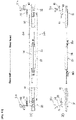
- Fig. 17 shows a pull-in device 15 and a pull-in force transmission part 50 according to a second embodiment of the present invention.
- the support shaft 7a is supported by the roller traveling body 21a, whereas in the second embodiment, the support shaft 7a is supported by the arm 19.
- the other configurations are substantially the same as those of the first embodiment, and thus the same reference numbers are attached them and description for them will be omitted.
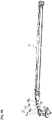
- Fig. 18 shows a pull-in device 15 and a pull-in force transmission part 51 according to a third embodiment of the present invention.
- the arm 19 is constituted of the one link
- an arm 52 is constituted of a plurality of links 53a, 53b, 53c.
- the plurality of links 53a, 53b, 53c are coupled so as to be capable of rotating around a vertical shaft 55.
- the arm 52 is constituted of the plurality of links 53a, 53b, 53c, it is possible to move the support shaft 7a along the inclined portion 12 even if the inclination of the inclined portion 12 of the rail 6a is steep.
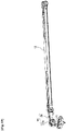
- Fig. 19 shows a pull-in device 15 and a pull-in force transmission part 56 according to a fourth embodiment of the present invention.
- the pull-in force transmission part 20 is constituted of the roller traveling body 21a and the arm 19, whereas in the fourth embodiment, the pull-in force transmission part 56 is constituted of the roller traveling body 21a.
- the roller traveling body 21a is coupled to the pull-in device 15 so as to be capable of rotating around the vertical shaft 54 without through any arms.
- the configuration of the roller traveling body 21a is substantially the same as that of the roller traveling body 21a of the first embodiment, and thus the same reference number is attached to it and description for it will be omitted.
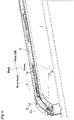
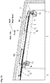
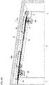
- Fig. 20 and Fig. 21 show a sliding door device 61 according to a fifth embodiment of the present invention.
- Fig. 20 shows a state that the sliding door 2 is in the closed position and
- Fig. 21 shows a state that the sliding door 2 is opened from the closed position to the predetermined position in the opening direction.
- the reference number "3" refers to a frame
- the reference number "4" refers to an opening
- the reference number "5" refers to a wall
- the reference number “8” refers to a blind plate
- the reference numbers "6a”, “6b” respectively refer to rails
- the reference numbers "7a”, “7b” respectively refer to support shafts.
- the rails 6a, 6b include the door head side rail 6a disposed on the door head side of the frame 3 and the door tail side rail 6b disposed on the door tail side of the frame 3.
- the rail 6a includes a straight portion 11 and an inclined portion 12 which is connected to an end portion of the straight portion 11 and inclined with respect to the straight portion 11.
- the rail 6b also includes a straight portion 11 and an inclined portion 12 which is connected to an end portion of the straight portion 11 and inclined with respect to the straight portion 11.
- the support shafts 7a, 7b includes the door head side support shaft 7a which can move on the rail 6a and the door tail side support shaft 7b which can move on the rail 6b.
- the support shaft 7a is supported by a roller traveling body 21a (see Fig. 22 ) which can travel on the rail 6a.
- the support shaft 7b is supported by a roller traveling body which can travel on the rail 6b.
- the support shaft 7a is attached to the door head side of the sliding door 2 through a bracket 13a.
- the support shaft 7b is attached to the door head side of the sliding door 2 through a bracket 13b. Since these configurations are the same as those of the sliding door device 1 of the first embodiment, the same reference numbers are attached to them and detailed description for them will be omitted.
- the pull-in device 15 which can linearly move along the straight portion 11 of the rail 6a is used for moving the support shaft 7a attached to the sliding door 2 along the inclined portion 12 of the rail 6a
- a trigger 62 which can linearly move along the straight portion 11 of the rail 6a is used for moving the support shaft 7a attached to the sliding door 2 along the inclined portion 12 of the rail 6a.
- a pull-in device 63a for capturing the trigger 62 to pull the trigger 62 is attached to the rail 6a.
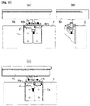
- Fig. 23(a) shows a horizontal cross-sectional view of the sliding door device 61 and Fig. 23(b) shows a side view of the sliding door device 61.
- the pull-in device 63a is attached to the straight portion 11 of the rail 6a.
- the pull-in device 63a includes a base 69 extending along the straight portion 11, a catcher 70 provided on the base 69 so as to be capable of sliding in the lengthwise direction of the base 69 and a spring (not shown in the drawings) disposed between the base 69 and the catcher 70.
- the pull-in device 63a is configured so that the catcher 70 rotates when the catcher 70 captures the trigger 62 to release engagement between the catcher 70 and the base 69 and thus the catcher 70 moves in the door head direction due to spring force of the spring. It is also possible to provide a linear damper for braking the movement of the catcher 70 in the door head direction. Since the configuration of the pull-in device 63a itself has been known in the art, further detailed description for it will be omitted.
- the trigger 62 when the sliding door 2 is closed, the trigger 62 is captured by the pull-in device 63a and linearly moves along the straight portion 11 of the rail 6a.
- the pull-in force transmission part 20 is coupled to the trigger 62.
- the pull-in force transmission part 20 moves the support shaft 7a along the inclined portion 12 according to linear movement of the trigger 62.
- the reference number "63b" in Fig. 20 refers to a pull-in device for capturing the trigger 62 to pull the trigger 62 to the door tail side.
- the pull-in device 63b is symmetrical with the pull-in device 63a and has substantially the same configuration as the pull-in device 63a.
- the pull-in device 63b generates pull-in force when the sliding door 2 is opened.
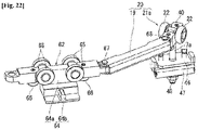
- the trigger 62 includes a trigger body 64, for example, four rollers 65 and, for example, two anti-vibration rollers 66.
- the trigger body 64 has an elongated rectangular parallelepiped body portion 64a contained in the straight portion 11 of the rail 6a and an engagement portion 64b which protrudes from the body portion 64a to the outside of the straight portion 11 of the rail 6a and can engage with the catcher 70 (see Fig. 23(b) ) of the pull-in device 63a.
- the rollers 65 are rotatably attached to side surfaces of the trigger body 64 and travel on both sides of a groove 11a (see Fig. 23(a) ) of the straight portion 11 of the rail 6a.
- the anti-vibration rollers 66 are rotatably attached to a bottom surface of the trigger body 64 and travel in the groove 11a of the straight portion 11.
- the pull-in force transmission part 20 includes the roller traveling body 21a and an arm 19 rotatably coupled to the roller traveling body 21a and the trigger 62.
- One end portion of the arm 19 is coupled to the trigger 62 so as to be capable of rotating around a vertical shaft 67.
- Another end portion of the arm 19 is coupled to the roller traveling body 21a so as to be capable of rotating around a vertical shaft 68. Since the configuration of the roller traveling body 21a is the same as the roller traveling body 21a of the first embodiment (see Fig. 12 ), the same reference number is attached to it and description for it will be omitted.
- Fig. 23 to Fig. 25 show operation diagrams of the sliding door device 61 when the sliding door 2 is closed.
- Fig. 23 shows a state before the pull-in device 63a captures the trigger 62.
- the trigger 62 moves along the straight portion 11 of the rail 6a together with the sliding door 2.
- the pull-in device 63a when the pull-in device 63a captures the trigger 62, the pull-in device 63a generates pull-in force in a direction of an arrow A and thus the trigger 62 linearly moves in the direction of the arrow A.
- the pull-in force acting on the trigger 62 is transmitted to the roller traveling body 21a through the arm 19.
- the roller traveling body 21a moves along the inclined portion 12 of the rail 6a in a direction of an arrow B. Since the support shaft 7a is attached to the roller traveling body 21a, the support shaft 7a moves along the inclined portion 12. Therefore, it is possible to obliquely pull the sliding door 2 in the direction of the arrow B.
- the configuration of the sliding door device 61 of the present embodiment has been described. According to the sliding door device 61 of the present embodiment, the following effects can be obtained.
- the pull-in force transmission part 20 is coupled to the trigger 62, it is possible to move the support shaft 7a attached to the sliding door 2 along the inclined portion 12 of the rail 6a by using the trigger 62 which can linearly move along the straight portion 11 of the rail 6a.
- the pull-in force transmission part 20 includes the arm 19 which is rotatably coupled to the roller traveling body 21a and the pull-in device 63a, it is possible to move the roller traveling body 21a to the vicinity of the tip end portion of the inclined portion 12 of the rail 6a.
- the arm 19 is constituted of the one link, it is possible to simplify the configuration of the arm 19.
- the sliding door is moved to the front side when the sliding door is closed in the above-described embodiments, the sliding door may be moved to the back side.
- the sliding door and the wall surface adjacent to the opening become flat in the closed position of the sliding door in the above-described embodiments, the sliding door and another slide door adjacent to the sliding door may become flat.
- the sliding door and the wall surface become flat in the closed position of the sliding door in the above-described embodiments
- the sliding door and the wall surface may not become flat.
- the sliding door may be in close contact with packing of the frame of the opening.
Landscapes
- Engineering & Computer Science (AREA)
- Mechanical Engineering (AREA)
- Support Devices For Sliding Doors (AREA)
- Wing Frames And Configurations (AREA)
Applications Claiming Priority (2)
| Application Number | Priority Date | Filing Date | Title |
|---|---|---|---|
| JP2019147829 | 2019-08-09 | ||
| PCT/JP2020/020896 WO2021029120A1 (ja) | 2019-08-09 | 2020-05-27 | 引戸装置 |
Publications (3)
| Publication Number | Publication Date |
|---|---|
| EP4012145A1 true EP4012145A1 (de) | 2022-06-15 |
| EP4012145A4 EP4012145A4 (de) | 2023-08-16 |
| EP4012145B1 EP4012145B1 (de) | 2024-09-11 |
Family
ID=74569409
Family Applications (1)
| Application Number | Title | Priority Date | Filing Date |
|---|---|---|---|
| EP20852514.7A Active EP4012145B1 (de) | 2019-08-09 | 2020-05-27 | Schiebetürvorrichtung |
Country Status (5)
| Country | Link |
|---|---|
| US (1) | US12006747B2 (de) |
| EP (1) | EP4012145B1 (de) |
| JP (1) | JP6990783B2 (de) |
| CN (1) | CN114144564B (de) |
| WO (1) | WO2021029120A1 (de) |
Families Citing this family (2)
| Publication number | Priority date | Publication date | Assignee | Title |
|---|---|---|---|---|
| EP4012145B1 (de) * | 2019-08-09 | 2024-09-11 | Sugatsune Kogyo Co., Ltd. | Schiebetürvorrichtung |
| CN219076970U (zh) * | 2023-01-16 | 2023-05-26 | 爱信(苏州)汽车技术中心有限公司 | 导向块 |
Family Cites Families (44)
| Publication number | Priority date | Publication date | Assignee | Title |
|---|---|---|---|---|
| JPS5952970B2 (ja) * | 1979-07-28 | 1984-12-22 | 富士通株式会社 | 光検出回路 |
| IT1184201B (it) * | 1985-03-25 | 1987-10-22 | Caimi Export Spa | Struttura di ante scorrevoli per mobili e simili |
| DE3831963A1 (de) | 1988-09-21 | 1990-03-29 | Hettich Paul Gmbh & Co | Falttuer mit mehreren fluegelpaaren |
| JPH06280439A (ja) * | 1991-04-25 | 1994-10-04 | Tostem Corp | 片引戸 |
| ES2097271T3 (es) * | 1992-09-24 | 1997-04-01 | Oclap Srl | Equipo de accionamiento de puertas de eyeccion para vehiculos de ferrocarril y tranvia. |
| US5483769A (en) * | 1993-12-07 | 1996-01-16 | Mark Iv Transportation Products Corporation | Door drive equipment for mass transit vehicle |
| NL1003674C2 (nl) * | 1996-07-24 | 1998-01-28 | Sab Wabco B V | Zwenkschuifdeurstelsel voor een voertuig. |
| IT1312027B1 (it) * | 1999-03-26 | 2002-04-04 | Antonio Giovannetti | Meccanismo e complesso per apertura-chiusura di ante complanari,adatto a consentire un movimento dell'anta parallelamente a se |
| JP3814520B2 (ja) * | 2001-11-15 | 2006-08-30 | アイシン精機株式会社 | 車両用スライドドア装置 |
| AT500017B8 (de) * | 2003-01-21 | 2007-02-15 | Knorr Bremse Gmbh | Schwenkschiebetür für fahrzeuge |
| US7028370B2 (en) * | 2003-03-31 | 2006-04-18 | Thk Co., Ltd. | Retracting apparatus, drawer apparatus and sliding door apparatus |
| DE502004005128D1 (de) * | 2004-04-10 | 2007-11-15 | Fahrzeugtechnik Dessau Ag Rail | Schwenkschiebetür für Schienenfahrzeuge |
| US7437852B2 (en) * | 2005-02-04 | 2008-10-21 | Dura Global Technologies, Inc. | Sliding window apparatus |
| DE202005015529U1 (de) * | 2005-10-04 | 2007-02-15 | Paul Hettich Gmbh & Co. Kg | Einzugsvorrichtung |
| US8096629B2 (en) * | 2005-11-29 | 2012-01-17 | Hardoor Mechanism Productions Ltd. | System for positioning sliding doors |
| JP5290538B2 (ja) * | 2007-05-18 | 2013-09-18 | 株式会社ニイテック | 引戸の引込み装置及び引戸装置 |
| US7654608B2 (en) * | 2008-03-11 | 2010-02-02 | Gm Global Technology Operations, Inc. | Extended-travel sliding door with articulating roller bracket |
| CA2803593C (en) * | 2010-07-16 | 2017-07-04 | Lester L. Mortier | Overhead door with spring-loaded roller hinges |
| JP5285679B2 (ja) * | 2010-11-16 | 2013-09-11 | 株式会社中尾製作所 | 引込装置 |
| DE102011010778B4 (de) * | 2011-02-09 | 2017-03-23 | Günther Zimmer | Beschleunigungs- und Verzögerungsvorrichtung mit Mitnahmeelement-Schwenkgelenk sowie ein System mit zwei ein Zug- und Abbremsvorrichtungspaar bildende Beschleunigungs- und Verzögerungsvorrichtungen |
| ITTV20110070A1 (it) * | 2011-05-23 | 2012-11-24 | Bortoluzzi Lab S R L | Dispositivo per ante scorrevoli a chiusura complanare, particolarmente per mobili e simili |
| US8402606B1 (en) * | 2011-10-18 | 2013-03-26 | Patrick Tsai | Door closer with buffer mechanism for a sliding door |
| DE102012103780A1 (de) * | 2012-04-30 | 2013-10-31 | Hettich-Heinze Gmbh & Co. Kg | Beschlag |
| US8745821B2 (en) * | 2012-10-24 | 2014-06-10 | Door & Window Hardware Co. | Auto-closing device for a sliding door |
| KR101249976B1 (ko) * | 2012-11-23 | 2013-04-03 | (주)지씨아이 | 미닫이식 도어의 개폐장치 |
| CN103573088B (zh) * | 2013-11-06 | 2016-04-20 | 宁波欧德意自动门有限公司 | 一种平移式医用门的自适应平衡吊架装置 |
| PL223707B1 (pl) * | 2014-01-30 | 2016-10-31 | Komandor Spółka Akcyjna | Domykacz do drzwi przesuwnych |
| US10920475B2 (en) | 2014-02-28 | 2021-02-16 | Sugatsune Kogyo Co., Ltd. | Sliding-door closer set |
| GB2566622B (en) | 2014-05-08 | 2019-07-10 | Tosoh F Tech Inc | 5-(Trifluoromethyl)pyrimidine derivatives and method for producing same |
| JP6356555B2 (ja) * | 2014-09-19 | 2018-07-11 | ナブテスコ株式会社 | プラグドア開閉装置およびプラグドア装置 |
| BR112017006971B1 (pt) * | 2014-10-12 | 2022-08-16 | Bortoluzzi Sistemi S.P.A | Item de mobília com mecanismo em aba |
| US9388622B1 (en) * | 2015-02-05 | 2016-07-12 | K.N. Crowder Mfg. Inc. | Apparatus for controlling the motion of a sliding door |
| DE102015003414B3 (de) * | 2015-03-17 | 2016-06-16 | Günther Zimmer | Kombinierte Beschleunigungs- und Verzögerungsvorrichtung mit Überlastschutz |
| DE102015003415B3 (de) * | 2015-03-17 | 2016-02-25 | Günther Zimmer | Beschleunigungs- und Verzögerungsvorrichtung mit geräuscharmer Bewegung |
| KR101718659B1 (ko) * | 2016-01-11 | 2017-03-21 | 신정철 | 슬라이딩도어의 자동닫힘장치 |
| KR101661081B1 (ko) | 2016-01-11 | 2016-09-28 | 신정철 | 다방향 회동가능한 슬라이딩도어 자동닫힘장치 |
| JP6804344B2 (ja) * | 2017-03-08 | 2020-12-23 | ナブテスコ株式会社 | ドア装置及びドア装置を備える車両 |
| DE102017107461A1 (de) * | 2017-04-06 | 2018-10-11 | Karl Simon Gmbh & Co. Kg | Bewegungsanordnung |
| US11585140B2 (en) * | 2018-09-06 | 2023-02-21 | Terno Scorrevoli S.P.A. Unipersonale | Shock-absorbing braking device for sliding panels and doors |
| JP6762998B2 (ja) * | 2018-09-07 | 2020-09-30 | スガツネ工業株式会社 | 引戸装置 |
| DE102018008201B4 (de) * | 2018-10-14 | 2022-12-22 | Günther Zimmer | Einzugsvorrichtung für zwei Endlagen, Schiebetür und Schiebetüranordnung |
| US11002054B2 (en) * | 2018-11-09 | 2021-05-11 | GM Global Technology Operations LLC | Sliding door mechanism |
| JP2020105832A (ja) * | 2018-12-27 | 2020-07-09 | パナソニックIpマネジメント株式会社 | 引戸装置 |
| EP4012145B1 (de) * | 2019-08-09 | 2024-09-11 | Sugatsune Kogyo Co., Ltd. | Schiebetürvorrichtung |
-
2020
- 2020-05-27 EP EP20852514.7A patent/EP4012145B1/de active Active
- 2020-05-27 JP JP2020549720A patent/JP6990783B2/ja active Active
- 2020-05-27 WO PCT/JP2020/020896 patent/WO2021029120A1/ja not_active Ceased
- 2020-05-27 US US17/632,177 patent/US12006747B2/en active Active
- 2020-05-27 CN CN202080051967.6A patent/CN114144564B/zh active Active
Also Published As
| Publication number | Publication date |
|---|---|
| CN114144564B (zh) | 2023-02-03 |
| WO2021029120A1 (ja) | 2021-02-18 |
| JP6990783B2 (ja) | 2022-01-12 |
| CN114144564A (zh) | 2022-03-04 |
| US12006747B2 (en) | 2024-06-11 |
| US20220228411A1 (en) | 2022-07-21 |
| EP4012145A4 (de) | 2023-08-16 |
| JPWO2021029120A1 (ja) | 2021-09-13 |
| EP4012145B1 (de) | 2024-09-11 |
Similar Documents
| Publication | Publication Date | Title |
|---|---|---|
| CN102187042B (zh) | 塞拉门装置 | |
| US8959709B2 (en) | Door opening and closing device | |
| EP4012145B1 (de) | Schiebetürvorrichtung | |
| EP3387950B1 (de) | Gleitschienenanordnung | |
| JP6815018B2 (ja) | 摺動ドアのためのガイドデバイス | |
| KR101946647B1 (ko) | 3중 연동 도어의 연동장치 | |
| US11408218B2 (en) | Sliding door device | |
| US20150183304A1 (en) | Front door device in vehicle | |
| JP2014167232A (ja) | 移動体駆動装置 | |
| US9145718B1 (en) | Latch assembly with an anti-picking function | |
| US11414905B2 (en) | Locking structure for a rectilinear center rail for opposite sliding doors | |
| JP2017031793A (ja) | 引戸装置 | |
| JPH0823245B2 (ja) | 引戸装置 | |
| KR102846951B1 (ko) | 슬라이딩 도어의 유동 방지 구조 | |
| RU2596945C2 (ru) | Отпирающее устройство эвакуационного выхода со скользящей защелкой | |
| JP5013610B2 (ja) | 吊戸ランナの隙間閉鎖機構付き軸受けストッパー | |
| JP5307769B2 (ja) | 自走往動させる機構 | |
| KR20040013285A (ko) | 글로브박스의 잠금장치 | |
| KR100748970B1 (ko) | 냉장고의 도어 개폐 장치 | |
| JP5691941B2 (ja) | 引戸用ブレーキ装置 | |
| KR101092781B1 (ko) | 래치장치 | |
| JP2008163587A (ja) | 切欠閉鎖部材及び切欠閉鎖部材を備えた建具 | |
| JP7186611B2 (ja) | 避難扉 | |
| JP2012132313A (ja) | 制動装置 | |
| WO2019066746A2 (en) | LOCKING MECHANISM FOR A SLIDING DOOR |
Legal Events
| Date | Code | Title | Description |
|---|---|---|---|
| STAA | Information on the status of an ep patent application or granted ep patent |
Free format text: STATUS: THE INTERNATIONAL PUBLICATION HAS BEEN MADE |
|
| PUAI | Public reference made under article 153(3) epc to a published international application that has entered the european phase |
Free format text: ORIGINAL CODE: 0009012 |
|
| STAA | Information on the status of an ep patent application or granted ep patent |
Free format text: STATUS: REQUEST FOR EXAMINATION WAS MADE |
|
| 17P | Request for examination filed |
Effective date: 20220301 |
|
| AK | Designated contracting states |
Kind code of ref document: A1 Designated state(s): AL AT BE BG CH CY CZ DE DK EE ES FI FR GB GR HR HU IE IS IT LI LT LU LV MC MK MT NL NO PL PT RO RS SE SI SK SM TR |
|
| DAV | Request for validation of the european patent (deleted) | ||
| DAX | Request for extension of the european patent (deleted) | ||
| A4 | Supplementary search report drawn up and despatched |
Effective date: 20230714 |
|
| RIC1 | Information provided on ipc code assigned before grant |
Ipc: E05F 1/16 20060101ALI20230710BHEP Ipc: E05D 15/06 20060101ALI20230710BHEP Ipc: E05D 15/10 20060101AFI20230710BHEP |
|
| GRAP | Despatch of communication of intention to grant a patent |
Free format text: ORIGINAL CODE: EPIDOSNIGR1 |
|
| STAA | Information on the status of an ep patent application or granted ep patent |
Free format text: STATUS: GRANT OF PATENT IS INTENDED |
|
| INTG | Intention to grant announced |
Effective date: 20240423 |
|
| GRAS | Grant fee paid |
Free format text: ORIGINAL CODE: EPIDOSNIGR3 |
|
| GRAA | (expected) grant |
Free format text: ORIGINAL CODE: 0009210 |
|
| STAA | Information on the status of an ep patent application or granted ep patent |
Free format text: STATUS: THE PATENT HAS BEEN GRANTED |
|
| AK | Designated contracting states |
Kind code of ref document: B1 Designated state(s): AL AT BE BG CH CY CZ DE DK EE ES FI FR GB GR HR HU IE IS IT LI LT LU LV MC MK MT NL NO PL PT RO RS SE SI SK SM TR |
|
| REG | Reference to a national code |
Ref country code: GB Ref legal event code: FG4D |
|
| REG | Reference to a national code |
Ref country code: CH Ref legal event code: EP |
|
| REG | Reference to a national code |
Ref country code: DE Ref legal event code: R096 Ref document number: 602020037709 Country of ref document: DE |
|
| REG | Reference to a national code |
Ref country code: IE Ref legal event code: FG4D |
|
| REG | Reference to a national code |
Ref country code: LT Ref legal event code: MG9D |
|
| PG25 | Lapsed in a contracting state [announced via postgrant information from national office to epo] |
Ref country code: NO Free format text: LAPSE BECAUSE OF FAILURE TO SUBMIT A TRANSLATION OF THE DESCRIPTION OR TO PAY THE FEE WITHIN THE PRESCRIBED TIME-LIMIT Effective date: 20241211 |
|
| REG | Reference to a national code |
Ref country code: NL Ref legal event code: MP Effective date: 20240911 |
|
| PG25 | Lapsed in a contracting state [announced via postgrant information from national office to epo] |
Ref country code: GR Free format text: LAPSE BECAUSE OF FAILURE TO SUBMIT A TRANSLATION OF THE DESCRIPTION OR TO PAY THE FEE WITHIN THE PRESCRIBED TIME-LIMIT Effective date: 20241212 Ref country code: FI Free format text: LAPSE BECAUSE OF FAILURE TO SUBMIT A TRANSLATION OF THE DESCRIPTION OR TO PAY THE FEE WITHIN THE PRESCRIBED TIME-LIMIT Effective date: 20240911 |
|
| PG25 | Lapsed in a contracting state [announced via postgrant information from national office to epo] |
Ref country code: BG Free format text: LAPSE BECAUSE OF FAILURE TO SUBMIT A TRANSLATION OF THE DESCRIPTION OR TO PAY THE FEE WITHIN THE PRESCRIBED TIME-LIMIT Effective date: 20240911 |
|
| PG25 | Lapsed in a contracting state [announced via postgrant information from national office to epo] |
Ref country code: LV Free format text: LAPSE BECAUSE OF FAILURE TO SUBMIT A TRANSLATION OF THE DESCRIPTION OR TO PAY THE FEE WITHIN THE PRESCRIBED TIME-LIMIT Effective date: 20240911 |
|
| PG25 | Lapsed in a contracting state [announced via postgrant information from national office to epo] |
Ref country code: HR Free format text: LAPSE BECAUSE OF FAILURE TO SUBMIT A TRANSLATION OF THE DESCRIPTION OR TO PAY THE FEE WITHIN THE PRESCRIBED TIME-LIMIT Effective date: 20240911 |
|
| PG25 | Lapsed in a contracting state [announced via postgrant information from national office to epo] |
Ref country code: RS Free format text: LAPSE BECAUSE OF FAILURE TO SUBMIT A TRANSLATION OF THE DESCRIPTION OR TO PAY THE FEE WITHIN THE PRESCRIBED TIME-LIMIT Effective date: 20241211 Ref country code: ES Free format text: LAPSE BECAUSE OF FAILURE TO SUBMIT A TRANSLATION OF THE DESCRIPTION OR TO PAY THE FEE WITHIN THE PRESCRIBED TIME-LIMIT Effective date: 20240911 |
|
| PG25 | Lapsed in a contracting state [announced via postgrant information from national office to epo] |
Ref country code: RS Free format text: LAPSE BECAUSE OF FAILURE TO SUBMIT A TRANSLATION OF THE DESCRIPTION OR TO PAY THE FEE WITHIN THE PRESCRIBED TIME-LIMIT Effective date: 20241211 Ref country code: NO Free format text: LAPSE BECAUSE OF FAILURE TO SUBMIT A TRANSLATION OF THE DESCRIPTION OR TO PAY THE FEE WITHIN THE PRESCRIBED TIME-LIMIT Effective date: 20241211 Ref country code: LV Free format text: LAPSE BECAUSE OF FAILURE TO SUBMIT A TRANSLATION OF THE DESCRIPTION OR TO PAY THE FEE WITHIN THE PRESCRIBED TIME-LIMIT Effective date: 20240911 Ref country code: HR Free format text: LAPSE BECAUSE OF FAILURE TO SUBMIT A TRANSLATION OF THE DESCRIPTION OR TO PAY THE FEE WITHIN THE PRESCRIBED TIME-LIMIT Effective date: 20240911 Ref country code: GR Free format text: LAPSE BECAUSE OF FAILURE TO SUBMIT A TRANSLATION OF THE DESCRIPTION OR TO PAY THE FEE WITHIN THE PRESCRIBED TIME-LIMIT Effective date: 20241212 Ref country code: FI Free format text: LAPSE BECAUSE OF FAILURE TO SUBMIT A TRANSLATION OF THE DESCRIPTION OR TO PAY THE FEE WITHIN THE PRESCRIBED TIME-LIMIT Effective date: 20240911 Ref country code: ES Free format text: LAPSE BECAUSE OF FAILURE TO SUBMIT A TRANSLATION OF THE DESCRIPTION OR TO PAY THE FEE WITHIN THE PRESCRIBED TIME-LIMIT Effective date: 20240911 Ref country code: BG Free format text: LAPSE BECAUSE OF FAILURE TO SUBMIT A TRANSLATION OF THE DESCRIPTION OR TO PAY THE FEE WITHIN THE PRESCRIBED TIME-LIMIT Effective date: 20240911 |
|
| REG | Reference to a national code |
Ref country code: AT Ref legal event code: MK05 Ref document number: 1722810 Country of ref document: AT Kind code of ref document: T Effective date: 20240911 |
|
| PG25 | Lapsed in a contracting state [announced via postgrant information from national office to epo] |
Ref country code: NL Free format text: LAPSE BECAUSE OF FAILURE TO SUBMIT A TRANSLATION OF THE DESCRIPTION OR TO PAY THE FEE WITHIN THE PRESCRIBED TIME-LIMIT Effective date: 20240911 |
|
| PG25 | Lapsed in a contracting state [announced via postgrant information from national office to epo] |
Ref country code: PT Free format text: LAPSE BECAUSE OF FAILURE TO SUBMIT A TRANSLATION OF THE DESCRIPTION OR TO PAY THE FEE WITHIN THE PRESCRIBED TIME-LIMIT Effective date: 20250113 Ref country code: IS Free format text: LAPSE BECAUSE OF FAILURE TO SUBMIT A TRANSLATION OF THE DESCRIPTION OR TO PAY THE FEE WITHIN THE PRESCRIBED TIME-LIMIT Effective date: 20250111 |
|
| PG25 | Lapsed in a contracting state [announced via postgrant information from national office to epo] |
Ref country code: RO Free format text: LAPSE BECAUSE OF FAILURE TO SUBMIT A TRANSLATION OF THE DESCRIPTION OR TO PAY THE FEE WITHIN THE PRESCRIBED TIME-LIMIT Effective date: 20240911 Ref country code: SM Free format text: LAPSE BECAUSE OF FAILURE TO SUBMIT A TRANSLATION OF THE DESCRIPTION OR TO PAY THE FEE WITHIN THE PRESCRIBED TIME-LIMIT Effective date: 20240911 |
|
| PG25 | Lapsed in a contracting state [announced via postgrant information from national office to epo] |
Ref country code: EE Free format text: LAPSE BECAUSE OF FAILURE TO SUBMIT A TRANSLATION OF THE DESCRIPTION OR TO PAY THE FEE WITHIN THE PRESCRIBED TIME-LIMIT Effective date: 20240911 Ref country code: AT Free format text: LAPSE BECAUSE OF FAILURE TO SUBMIT A TRANSLATION OF THE DESCRIPTION OR TO PAY THE FEE WITHIN THE PRESCRIBED TIME-LIMIT Effective date: 20240911 |
|
| PG25 | Lapsed in a contracting state [announced via postgrant information from national office to epo] |
Ref country code: CZ Free format text: LAPSE BECAUSE OF FAILURE TO SUBMIT A TRANSLATION OF THE DESCRIPTION OR TO PAY THE FEE WITHIN THE PRESCRIBED TIME-LIMIT Effective date: 20240911 Ref country code: PL Free format text: LAPSE BECAUSE OF FAILURE TO SUBMIT A TRANSLATION OF THE DESCRIPTION OR TO PAY THE FEE WITHIN THE PRESCRIBED TIME-LIMIT Effective date: 20240911 |
|
| PG25 | Lapsed in a contracting state [announced via postgrant information from national office to epo] |
Ref country code: SK Free format text: LAPSE BECAUSE OF FAILURE TO SUBMIT A TRANSLATION OF THE DESCRIPTION OR TO PAY THE FEE WITHIN THE PRESCRIBED TIME-LIMIT Effective date: 20240911 |
|
| REG | Reference to a national code |
Ref country code: DE Ref legal event code: R097 Ref document number: 602020037709 Country of ref document: DE |
|
| PGFP | Annual fee paid to national office [announced via postgrant information from national office to epo] |
Ref country code: DE Payment date: 20250402 Year of fee payment: 6 |
|
| PG25 | Lapsed in a contracting state [announced via postgrant information from national office to epo] |
Ref country code: DK Free format text: LAPSE BECAUSE OF FAILURE TO SUBMIT A TRANSLATION OF THE DESCRIPTION OR TO PAY THE FEE WITHIN THE PRESCRIBED TIME-LIMIT Effective date: 20240911 |
|
| PGFP | Annual fee paid to national office [announced via postgrant information from national office to epo] |
Ref country code: BE Payment date: 20250410 Year of fee payment: 6 Ref country code: IT Payment date: 20250422 Year of fee payment: 6 |
|
| PLBE | No opposition filed within time limit |
Free format text: ORIGINAL CODE: 0009261 |
|
| STAA | Information on the status of an ep patent application or granted ep patent |
Free format text: STATUS: NO OPPOSITION FILED WITHIN TIME LIMIT |
|
| 26N | No opposition filed |
Effective date: 20250612 |
|
| PG25 | Lapsed in a contracting state [announced via postgrant information from national office to epo] |
Ref country code: SE Free format text: LAPSE BECAUSE OF FAILURE TO SUBMIT A TRANSLATION OF THE DESCRIPTION OR TO PAY THE FEE WITHIN THE PRESCRIBED TIME-LIMIT Effective date: 20240911 |
|
| REG | Reference to a national code |
Ref country code: CH Ref legal event code: H13 Free format text: ST27 STATUS EVENT CODE: U-0-0-H10-H13 (AS PROVIDED BY THE NATIONAL OFFICE) Effective date: 20251223 |
|
| PG25 | Lapsed in a contracting state [announced via postgrant information from national office to epo] |
Ref country code: LU Free format text: LAPSE BECAUSE OF NON-PAYMENT OF DUE FEES Effective date: 20250527 |
|
| PG25 | Lapsed in a contracting state [announced via postgrant information from national office to epo] |
Ref country code: CH Free format text: LAPSE BECAUSE OF NON-PAYMENT OF DUE FEES Effective date: 20250531 |
|
| GBPC | Gb: european patent ceased through non-payment of renewal fee |
Effective date: 20250527 |
|
| PG25 | Lapsed in a contracting state [announced via postgrant information from national office to epo] |
Ref country code: MC Free format text: LAPSE BECAUSE OF FAILURE TO SUBMIT A TRANSLATION OF THE DESCRIPTION OR TO PAY THE FEE WITHIN THE PRESCRIBED TIME-LIMIT Effective date: 20240911 |