EP4012136A1 - Verbindung für bodenplattenabdeckung und abdeckanordnung mit dieser verbindung - Google Patents
Verbindung für bodenplattenabdeckung und abdeckanordnung mit dieser verbindung Download PDFInfo
- Publication number
- EP4012136A1 EP4012136A1 EP19941184.4A EP19941184A EP4012136A1 EP 4012136 A1 EP4012136 A1 EP 4012136A1 EP 19941184 A EP19941184 A EP 19941184A EP 4012136 A1 EP4012136 A1 EP 4012136A1
- Authority
- EP
- European Patent Office
- Prior art keywords
- face
- joint
- coupling portions
- covering
- attachable element
- Prior art date
- Legal status (The legal status is an assumption and is not a legal conclusion. Google has not performed a legal analysis and makes no representation as to the accuracy of the status listed.)
- Granted
Links
Images


Classifications
-
- E—FIXED CONSTRUCTIONS
- E04—BUILDING
- E04F—FINISHING WORK ON BUILDINGS, e.g. STAIRS, FLOORS
- E04F19/00—Other details of constructional parts for finishing work on buildings
- E04F19/02—Borders; Finishing strips, e.g. beadings; Light coves
- E04F19/06—Borders; Finishing strips, e.g. beadings; Light coves specially designed for securing panels or masking the edges of wall- or floor-covering elements
- E04F19/061—Borders; Finishing strips, e.g. beadings; Light coves specially designed for securing panels or masking the edges of wall- or floor-covering elements used to finish off an edge or corner of a wall or floor covering area
-
- E—FIXED CONSTRUCTIONS
- E04—BUILDING
- E04F—FINISHING WORK ON BUILDINGS, e.g. STAIRS, FLOORS
- E04F19/00—Other details of constructional parts for finishing work on buildings
- E04F19/02—Borders; Finishing strips, e.g. beadings; Light coves
- E04F19/06—Borders; Finishing strips, e.g. beadings; Light coves specially designed for securing panels or masking the edges of wall- or floor-covering elements
- E04F19/062—Borders; Finishing strips, e.g. beadings; Light coves specially designed for securing panels or masking the edges of wall- or floor-covering elements used between similar elements
-
- E—FIXED CONSTRUCTIONS
- E04—BUILDING
- E04F—FINISHING WORK ON BUILDINGS, e.g. STAIRS, FLOORS
- E04F19/00—Other details of constructional parts for finishing work on buildings
- E04F19/02—Borders; Finishing strips, e.g. beadings; Light coves
- E04F19/06—Borders; Finishing strips, e.g. beadings; Light coves specially designed for securing panels or masking the edges of wall- or floor-covering elements
- E04F19/062—Borders; Finishing strips, e.g. beadings; Light coves specially designed for securing panels or masking the edges of wall- or floor-covering elements used between similar elements
- E04F19/063—Borders; Finishing strips, e.g. beadings; Light coves specially designed for securing panels or masking the edges of wall- or floor-covering elements used between similar elements for simultaneously securing panels having different thicknesses
-
- E—FIXED CONSTRUCTIONS
- E04—BUILDING
- E04F—FINISHING WORK ON BUILDINGS, e.g. STAIRS, FLOORS
- E04F19/00—Other details of constructional parts for finishing work on buildings
- E04F19/02—Borders; Finishing strips, e.g. beadings; Light coves
- E04F19/06—Borders; Finishing strips, e.g. beadings; Light coves specially designed for securing panels or masking the edges of wall- or floor-covering elements
- E04F19/065—Finishing profiles with a T-shaped cross-section or the like
- E04F19/066—Finishing profiles with a T-shaped cross-section or the like fixed onto a base profile by means of a separate connector
-
- E—FIXED CONSTRUCTIONS
- E04—BUILDING
- E04F—FINISHING WORK ON BUILDINGS, e.g. STAIRS, FLOORS
- E04F19/00—Other details of constructional parts for finishing work on buildings
- E04F19/02—Borders; Finishing strips, e.g. beadings; Light coves
- E04F19/06—Borders; Finishing strips, e.g. beadings; Light coves specially designed for securing panels or masking the edges of wall- or floor-covering elements
- E04F19/065—Finishing profiles with a T-shaped cross-section or the like
- E04F19/068—Finishing profiles with a T-shaped cross-section or the like with means allowing a tipping movement
Definitions
- the present invention relates to the industry dedicated to covering floors by means of panels in the form of laminate flooring, parquet or floating floors, and more specifically to the industry dedicated to joints for said panels.
- panels to be arranged covering floors in the form of laminate flooring, parquet or floating platforms are widely known.
- the panels can be arranged in any shape, such as square or rectangular.
- said panels can be arranged such that they have a haptic and optical appearance corresponding to wood, concrete, etc.
- These panels are made of one or more materials. Regardless of the material, said panels inevitably undergo contractions and expansions due to changes in temperature. These phenomena entail a variation in the dimension of each of the panels, as well as of the complete assembly thereof. In this way, there are hollow slots between panels, according to the contractions, as well as lifting of at least some of the panels, according to the expansions.
- expansion joints configured to allow for dimensional variations are conventionally arranged. Specifically, these joints are configured to enable movement of the edges of the adjoining panels separated by said joints, the expansion joints being additionally on the panels such that the edges are hidden from view. These expansion joints also prevent the arrangement of hollow slots between the panels, which is undesirable from both a hygienic and aesthetic point of view.
- edges of the panels must be arranged. These edges may correspond to a location of inaccessible elements, such as a partition or wall.
- the described expansion joints or even other expansion joints adapted to this arrangement, are conventionally arranged, such that they enable movement of the panels with respect to said inaccessible elements.
- delimiting elements of the edges of the panels must be arranged when said edges correspond to an ending of the panels.
- This ending corresponds to a sharp downward unevenness to a height of the floor itself.
- transition joints are conventionally arranged to provide an element that covers the edge of the panels, while doing so progressively. In this way, by placing the transition joints, said edges are prevented from being exposed to the view, in addition to preventing tripping and the like with said edges as a consequence of the corresponding sudden unevenness.
- the present invention provides a joint for floor covering panels, the joint comprising a covering profile that has at least one extension with a hidden face to be arranged facing the floor and an exposed face, opposite to the hidden face and to be arranged so that it is visible.
- This joint additionally comprises a base profile with a resting face to be arranged making contact with the floor and a supporting face to be arranged facing the hidden face; and coupling elements to establish a coupled arrangement between the covering profile and the base profile.
- the coupling elements comprise two coupling portions on the base profile, each of the two coupling portions being defined according to a different angle with respect to the resting face; and an attachable element for being coupled in any one of the two coupling portions, the attachable element projecting from the hidden face.
- the coupled arrangement can be established such that the exposed face has a different inclination with respect to the resting face according to each of the two coupled portions.
- the at least one extension is curved such that the hidden face has a concave shape and the exposed face has a convex shape. Additionally or alternatively, the at least one extension is preferably elastically deformable.
- the coupling elements are configured to establish the aforementioned coupled arrangement by snap fitting the attachable element in correspondence with one of the two coupling portions.
- the coupling elements preferably comprise contact surfaces configured to establish a retention between the base profile and the covering profile according to the coupled arrangement.
- the contact surfaces are preferably defined by irregularities, the irregularities being complementary to each other according to the coupled arrangement.
- the attachable element is configured as a female element and each of the two coupling portions is determined by a male element, such that the coupled arrangement is established by inserting any one of the two coupling portions into the attachable element.
- the attachable element comprises at least one flange and the two coupling portions comprise two ribs, the at least one flange being arranged to receive any one of the two ribs between each other.
- the attachable element is configured as a male element and each of the two coupling portions is determined by a female element, such that the coupled arrangement is established by inserting the attachable element into any one of the two coupling portions.
- the attachable element comprises a protrusion and the two coupling portions comprise projections, the protrusion being arranged for insertion between the projections. Accordingly, there are preferably three projections, such that one of the projections simultaneously forms part of the two coupling portions.
- the present invention provides a covering assembly for covering floors, which comprises the present joint and at least one of the aforementioned panels.
- said cover assembly additionally comprises a cladding configured to be arranged between the at least one panel and the floor.
- the cladding has a thickness that is substantially the same as a minimum separation measurement between a resting face and a supporting face of a base profile comprised in the joint.
- the present invention relates to a joint comprising a covering profile (1) and a base profile (2), this joint being for making contact with panels (3) for covering floors (4).
- the panels (3) can correspond to laminate flooring, parquet or floating floors.
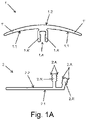
- the covering profile (1) has an elongated configuration. Likewise, said profile (1) has at least one extension (1'), and preferably two, with a hidden face (1.1) to be arranged facing the floor (4) and an exposed face (1.2), opposite to the hidden face (1.1) and to be arranged so that it is visible.
- the extensions (1') extend longitudinally along the covering profile (1).
- Each of the extensions (1') is elastically deformable. In this way, the extensions (1') are deformable or moveable to adapt to different thicknesses of the panels (3) providing contact therewith, either due to the thickness of each of the panels (3) or due to a change in the thickness of the panels (3) because of the expansion thereof. Likewise, since there are two extensions (1'), these extensions (1') are joined or formed from an intermediate zone.
- the extensions (1') are arranged to determine the contact with the panels (3) or the corresponding floor (4) by means of an end point thereof, in addition to contacting according to the hidden face (1.1).
- the hidden face (1.A) has a concave shape.
- the hidden face (1.A) has preferably a continuous surface, i.e., devoid of surface irregularities, although it can be arranged separated into two portions when the covering profile (1) has two of the described extensions (1').
- the exposed face (1.B) has a convex shape.
- the exposed face (1.B) has a preferably continuous surface, i.e., without surface irregularities.
- the base profile (2) has an elongated configuration. Likewise, said profile (2) has a resting face (2.1) to be arranged making contact with the floor (4), or at least facing the same, and a supporting face (2.2) to be arranged facing the hidden face (1.1) of the covering profile (1).
- the resting face (2.1) and the supporting face (2.2) are configured such that they form part of a portion in the shape of a laminar body, preferably being parallel to each other.
- these faces (2.1, 2.2) extend laterally and longitudinally such that the corresponding panels (3) are arranged on the supporting face (2.2).
- said laminar body or a minimum separation distance between the resting face (2.1) and the supporting face (2.2) is selected according to a thickness of a cladding (5).
- this cladding (5) has acoustic insulation and/or soundproofing properties.
- said cladding (5) is configured to be arranged between the panels (3) and the floor (4).
- the cladding (5) is configured to provide cushioning when stepped on by users, both directly and through the corresponding panels (3).
- the present invention also relates to a covering assembly for covering the corresponding floor (4), said assembly comprising the covering profile (1), the base profile (2) and at least one of the panels (3), and preferably a plurality thereof (3).
- the covering assembly additionally comprises the cladding (5).
- the thickness of the aforementioned cladding (5) and the minimum separation distance between the resting face (2.1) and the supporting face (2.2) are preferably at least substantially the same, and more preferably the same.
- the joint comprises coupling elements to establish a coupled arrangement between the covering profile (1) and the base profile (2).
- the coupling elements are configured such that the coupled arrangement between the covering profile (1) and the base profile (2) can be established according to two positions different from each other, so that the exposed face (1.2) can be arranged according to different positions and has a different inclination with respect to the resting face (2.1) according to each of the two positions.
- the coupling elements are configured to establish the coupled arrangement by snap fitting.
- said coupling elements comprise contact surfaces configured to establish a retention between the base profile (2) and the covering profile (1) according to the coupled arrangement.
- the contact surfaces are preferably defined with irregularities, the irregularities being complementary to each other according to the coupled arrangement.
- the contact surfaces have teeth and grooves. These irregularities can be selected such that the teeth are more or less pointed, as can be seen in Figures 1B and 1D , respectively.
- the coupling elements comprise an attachable element (1.A; 1.B) in the covering profile (1) and two coupling portions (2.A; 2.B) in the base profile (2).
- Each of the two coupling portions (2.A; 2.B) is defined according to a different angle, this angle being definable as a function of a lateral or transverse inclination according to the elongated configuration of the base profile (2) and with respect to a perpendicularity of the resting face (2.1). See the cross sections shown, for example, in Figures 1A , 1B, 1C and 1D of said base profile (2).
- the attachable element (1.A; 1.B) for its part, is arranged to be coupled in any one of the two coupling portions (2.A; 2.B), this element (1.A; 1.B) projecting from the hidden face (1.1).
- the coupling portions (2.A; 2.B) and the attachable element (1.A; 1.B) are arranged according to a continuous distribution along the base profile (2) and the covering profile (1), respectively.
- the coupling portions (2.A; 2.B) and/or the attachable element (1.A; 1.B) are arranged according to a punctual distribution along the corresponding profile (2, 1).
- the coupling elements are preferably configured such that, by means of pressing, the attachable element (1.A; 1.B) is arranged retained in correspondence with one of the two coupling portions (2.A; 2.B).
- the attachable element (1.A) is configured as a female element and each of the two coupling portions (2.A) is determined by a male element. Accordingly, the coupled arrangement is established by inserting any one of the two coupling portions (2.A) into the attachable member (1.A). See Figures 1A , 2A , 3A and 4A .
- the attachable element (1.A) comprises at least one flange (1.A') and each of the two coupling portions (2.A) comprises a rib (2.A'), the at least one flange (1.A') being arranged to receive any one of the two ribs (2.A') between each other.
- the coupling portions (2.A) and the attachable element (1.A) are arranged according to the punctual distribution, or when only the attachable element (1.A) is arranged according to the punctual distribution, there are preferably two flanges (1 .A'), these flanges being arranged such that together they laterally surround the corresponding rib (2.A').
- the coupling portions (2.A) and the attachable element (1.A) are arranged according to the continuous distribution along the base profile (2) and the covering profile (1), respectively, there are preferably two flanges (1.A'), these flanges being arranged such that together they laterally surround the corresponding rib (2.A'). This enables both the covering profile (1) and the base profile (2) to be obtained by extrusion.
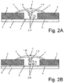
- the attachable element (1.B) is configured as a male element and each of the two coupling portions (2.B) is determined by a female element. Accordingly, the coupled arrangement is established by inserting the attachable element (1.B) into any one of the two coupling portions (2.B). See Figures 1B , 2B , 3B and 4B .
- the attachable element (1.B) comprises a protrusion (1.B') and the two coupling portions (2.B) comprise projections (2.B'), the protrusion (1.B') being arranged for insertion between the projections (2.B'). More specifically, there are three projections (2.B'), such that one of the projections (2.B') simultaneously forms part of the two coupling portions (2.A). Likewise, the protrusion (1.B') is arranged for insertion between two of the three projections (2.B').
- the coupling portions (2.B) can be arranged according to the punctual distribution.
- the protrusion (1.B') can be arranged according to the punctual distribution. Accordingly, both the coupling portions (2.B) and the protrusion (1.B') being arranged according to the punctual distribution, the attachable element (1.B) and the two coupling portions (2. B) are arranged such that they are the same and establish the coupled arrangement with each other.
- the covering profile (1) and the base profile (2) can be arranged coupled to each other, for example, longitudinally between two of the panels (3), each of these panels being contacted by one of the extensions (1') through the hidden face (1.1).
- the joint can be arranged as an expansion joint between said panels (3), while covering a variable distance between the panels as a result of the expansions. See Figures 2A and 2B .
- the covering profile (1) and the base profile (2) can be arranged coupled to each other, for example, as an ending on the floor (4) for arranging the panels (3).
- the joint can be arranged as a transition joint between the corresponding panels (3) and the floor (4), in addition to performing the function of an expansion joint for said panels (3), such that a change in level between the panels (3) and the floor (4) is provided in a less abrupt and continuous manner. See Figures 3A and 3B .
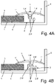
- the covering profile (1) and the base profile (2) can be arranged coupled to each other, for example, as a finish for one or more of the panels (3) in correspondence or in proximity to an obstacle or inaccessible element such as a wall (6).
- the joint can be arranged as an expansion joint between said panels (3) and the wall, while covering a variable separation between the panels (3) and said wall (6) as a result of the expansions. See Figures 4A and 4B .
Landscapes
- Engineering & Computer Science (AREA)
- Architecture (AREA)
- Civil Engineering (AREA)
- Structural Engineering (AREA)
- Floor Finish (AREA)
- Road Paving Structures (AREA)
Applications Claiming Priority (1)
| Application Number | Priority Date | Filing Date | Title |
|---|---|---|---|
| PCT/ES2019/070561 WO2021028603A1 (es) | 2019-08-09 | 2019-08-09 | Junta para paneles de cubrimiento de pavimento y conjunto de cubrimiento que comprende dicha junta |
Publications (3)
| Publication Number | Publication Date |
|---|---|
| EP4012136A1 true EP4012136A1 (de) | 2022-06-15 |
| EP4012136A4 EP4012136A4 (de) | 2023-06-21 |
| EP4012136B1 EP4012136B1 (de) | 2024-05-01 |
Family
ID=74570925
Family Applications (1)
| Application Number | Title | Priority Date | Filing Date |
|---|---|---|---|
| EP19941184.4A Active EP4012136B1 (de) | 2019-08-09 | 2019-08-09 | Verbindung für bodenplattenabdeckung und abdeckanordnung mit dieser verbindung |
Country Status (5)
| Country | Link |
|---|---|
| US (1) | US11939780B2 (de) |
| EP (1) | EP4012136B1 (de) |
| ES (1) | ES2986697T3 (de) |
| PT (1) | PT4012136T (de) |
| WO (1) | WO2021028603A1 (de) |
Families Citing this family (1)
| Publication number | Priority date | Publication date | Assignee | Title |
|---|---|---|---|---|
| USD919124S1 (en) * | 2018-06-26 | 2021-05-11 | Ram Manufacturing Ltd | Sunroom wall assembly kit |
Family Cites Families (7)
| Publication number | Priority date | Publication date | Assignee | Title |
|---|---|---|---|---|
| US4858405A (en) * | 1987-07-10 | 1989-08-22 | Christie Dawson A | Building system for windows, enclosures, buildings and the like |
| DE20300716U1 (de) * | 2003-01-17 | 2003-07-10 | Carl Prinz GmbH & Co. Metallwarenfabrik, 47574 Goch | Profilsystem für Böden |
| EP1680563B1 (de) | 2003-10-21 | 2013-04-03 | Profiline | Anordnung zur Verbindung von Bodenbelägen |
| DE10349932A1 (de) * | 2003-10-24 | 2005-05-25 | Herm. Friedr. Künne Gmbh & Co. | Fußbodenprofilanordnung |
| US8747596B2 (en) * | 2005-01-12 | 2014-06-10 | Flooring Industries Limited, Sarl | Finishing set for floor covering and holder, as well as finishing profile, for a finishing set, and method for manufacturing a finishing profile and a skirting board |
| DE102007009364B4 (de) * | 2007-02-02 | 2010-10-21 | Proverum Ag | Profilleistensystem, insbesondere zum Randabschluß und/oder zur Fugenabdeckung, für einen Belag |
| US10138639B2 (en) * | 2016-07-11 | 2018-11-27 | Unilin North America Llc | Molding assembly and floor installation |
-
2019
- 2019-08-09 EP EP19941184.4A patent/EP4012136B1/de active Active
- 2019-08-09 US US17/633,892 patent/US11939780B2/en active Active
- 2019-08-09 PT PT199411844T patent/PT4012136T/pt unknown
- 2019-08-09 ES ES19941184T patent/ES2986697T3/es active Active
- 2019-08-09 WO PCT/ES2019/070561 patent/WO2021028603A1/es not_active Ceased
Also Published As
| Publication number | Publication date |
|---|---|
| ES2986697T3 (es) | 2024-11-12 |
| EP4012136B1 (de) | 2024-05-01 |
| EP4012136A4 (de) | 2023-06-21 |
| US11939780B2 (en) | 2024-03-26 |
| WO2021028603A1 (es) | 2021-02-18 |
| PT4012136T (pt) | 2024-07-29 |
| US20220325534A1 (en) | 2022-10-13 |
Similar Documents
| Publication | Publication Date | Title |
|---|---|---|
| CA2443022C (en) | Panel assembly for joining flat, thin members that adjoin each other | |
| KR100413372B1 (ko) | 건축용 마루 패널을 깔아서 결합시키는 방법, 건축물 마루 시공 방법, 및 건축물 마루 패널의 분해 방법 | |
| CA2809984C (en) | Covering panel and method for assembling a plurality of same | |
| KR100528708B1 (ko) | 패널부재 | |
| US7958689B2 (en) | Floor panel with coupling devices | |
| US12037787B2 (en) | Ceiling system | |
| JP5237769B2 (ja) | 異形材レールシステム | |
| US20100186332A1 (en) | Molding profile and molding profile assembly | |
| JP2004520502A (ja) | フロアボード及び係止システム | |
| US20210332595A1 (en) | Cladding element | |
| US11939780B2 (en) | Joint for floor covering panels and covering assembly comprising said joint | |
| JPH0656310U (ja) | 床 板 | |
| GB2248864A (en) | Union of siding material with tiles | |
| US20220220745A1 (en) | Quad spacer for installation of flooring systems | |
| JP5385477B1 (ja) | 上がり框及び床見切材 | |
| JP4118778B2 (ja) | 隅部用長尺気密シート | |
| KR200400647Y1 (ko) | 코너 이음 부재 | |
| JPH0721715Y2 (ja) | 鎧型横張内外装材用目地部材 | |
| JPH0229149Y2 (de) | ||
| CN115341732A (zh) | 组合式墙地砖的铺装方法 | |
| JP2551833Y2 (ja) | 天井下地ジョイナ | |
| JPH0720272Y2 (ja) | 鎧型横張内外装材用出隅部材 | |
| KR101459209B1 (ko) | 조립식 바닥재 | |
| KR20160004542A (ko) | 곡선 조립이 가능한 조립식 벽돌 | |
| JPH05272224A (ja) | 屋外用床板のつなぎ構造 |
Legal Events
| Date | Code | Title | Description |
|---|---|---|---|
| STAA | Information on the status of an ep patent application or granted ep patent |
Free format text: STATUS: THE INTERNATIONAL PUBLICATION HAS BEEN MADE |
|
| PUAI | Public reference made under article 153(3) epc to a published international application that has entered the european phase |
Free format text: ORIGINAL CODE: 0009012 |
|
| STAA | Information on the status of an ep patent application or granted ep patent |
Free format text: STATUS: REQUEST FOR EXAMINATION WAS MADE |
|
| 17P | Request for examination filed |
Effective date: 20220303 |
|
| AK | Designated contracting states |
Kind code of ref document: A1 Designated state(s): AL AT BE BG CH CY CZ DE DK EE ES FI FR GB GR HR HU IE IS IT LI LT LU LV MC MK MT NL NO PL PT RO RS SE SI SK SM TR |
|
| DAV | Request for validation of the european patent (deleted) | ||
| DAX | Request for extension of the european patent (deleted) | ||
| A4 | Supplementary search report drawn up and despatched |
Effective date: 20230524 |
|
| P01 | Opt-out of the competence of the unified patent court (upc) registered |
Effective date: 20230517 |
|
| RIC1 | Information provided on ipc code assigned before grant |
Ipc: E04F 19/06 20060101AFI20230517BHEP |
|
| GRAP | Despatch of communication of intention to grant a patent |
Free format text: ORIGINAL CODE: EPIDOSNIGR1 |
|
| STAA | Information on the status of an ep patent application or granted ep patent |
Free format text: STATUS: GRANT OF PATENT IS INTENDED |
|
| INTG | Intention to grant announced |
Effective date: 20240124 |
|
| GRAS | Grant fee paid |
Free format text: ORIGINAL CODE: EPIDOSNIGR3 |
|
| GRAA | (expected) grant |
Free format text: ORIGINAL CODE: 0009210 |
|
| STAA | Information on the status of an ep patent application or granted ep patent |
Free format text: STATUS: THE PATENT HAS BEEN GRANTED |
|
| AK | Designated contracting states |
Kind code of ref document: B1 Designated state(s): AL AT BE BG CH CY CZ DE DK EE ES FI FR GB GR HR HU IE IS IT LI LT LU LV MC MK MT NL NO PL PT RO RS SE SI SK SM TR |
|
| REG | Reference to a national code |
Ref country code: GB Ref legal event code: FG4D |
|
| REG | Reference to a national code |
Ref country code: CH Ref legal event code: EP |
|
| REG | Reference to a national code |
Ref country code: IE Ref legal event code: FG4D |
|
| REG | Reference to a national code |
Ref country code: DE Ref legal event code: R096 Ref document number: 602019051769 Country of ref document: DE |
|
| REG | Reference to a national code |
Ref country code: PT Ref legal event code: SC4A Ref document number: 4012136 Country of ref document: PT Date of ref document: 20240729 Kind code of ref document: T Free format text: AVAILABILITY OF NATIONAL TRANSLATION Effective date: 20240722 |
|
| REG | Reference to a national code |
Ref country code: LT Ref legal event code: MG9D |
|
| REG | Reference to a national code |
Ref country code: NL Ref legal event code: MP Effective date: 20240501 |
|
| PG25 | Lapsed in a contracting state [announced via postgrant information from national office to epo] |
Ref country code: IS Free format text: LAPSE BECAUSE OF FAILURE TO SUBMIT A TRANSLATION OF THE DESCRIPTION OR TO PAY THE FEE WITHIN THE PRESCRIBED TIME-LIMIT Effective date: 20240901 |
|
| PG25 | Lapsed in a contracting state [announced via postgrant information from national office to epo] |
Ref country code: BG Free format text: LAPSE BECAUSE OF FAILURE TO SUBMIT A TRANSLATION OF THE DESCRIPTION OR TO PAY THE FEE WITHIN THE PRESCRIBED TIME-LIMIT Effective date: 20240501 |
|
| PG25 | Lapsed in a contracting state [announced via postgrant information from national office to epo] |
Ref country code: HR Free format text: LAPSE BECAUSE OF FAILURE TO SUBMIT A TRANSLATION OF THE DESCRIPTION OR TO PAY THE FEE WITHIN THE PRESCRIBED TIME-LIMIT Effective date: 20240501 Ref country code: FI Free format text: LAPSE BECAUSE OF FAILURE TO SUBMIT A TRANSLATION OF THE DESCRIPTION OR TO PAY THE FEE WITHIN THE PRESCRIBED TIME-LIMIT Effective date: 20240501 |
|
| PG25 | Lapsed in a contracting state [announced via postgrant information from national office to epo] |
Ref country code: GR Free format text: LAPSE BECAUSE OF FAILURE TO SUBMIT A TRANSLATION OF THE DESCRIPTION OR TO PAY THE FEE WITHIN THE PRESCRIBED TIME-LIMIT Effective date: 20240802 |
|
| REG | Reference to a national code |
Ref country code: AT Ref legal event code: MK05 Ref document number: 1682541 Country of ref document: AT Kind code of ref document: T Effective date: 20240501 |
|
| PG25 | Lapsed in a contracting state [announced via postgrant information from national office to epo] |
Ref country code: NL Free format text: LAPSE BECAUSE OF FAILURE TO SUBMIT A TRANSLATION OF THE DESCRIPTION OR TO PAY THE FEE WITHIN THE PRESCRIBED TIME-LIMIT Effective date: 20240501 |
|
| PG25 | Lapsed in a contracting state [announced via postgrant information from national office to epo] |
Ref country code: AT Free format text: LAPSE BECAUSE OF FAILURE TO SUBMIT A TRANSLATION OF THE DESCRIPTION OR TO PAY THE FEE WITHIN THE PRESCRIBED TIME-LIMIT Effective date: 20240501 |
|
| PG25 | Lapsed in a contracting state [announced via postgrant information from national office to epo] |
Ref country code: PL Free format text: LAPSE BECAUSE OF FAILURE TO SUBMIT A TRANSLATION OF THE DESCRIPTION OR TO PAY THE FEE WITHIN THE PRESCRIBED TIME-LIMIT Effective date: 20240501 |
|
| PG25 | Lapsed in a contracting state [announced via postgrant information from national office to epo] |
Ref country code: LV Free format text: LAPSE BECAUSE OF FAILURE TO SUBMIT A TRANSLATION OF THE DESCRIPTION OR TO PAY THE FEE WITHIN THE PRESCRIBED TIME-LIMIT Effective date: 20240501 |
|
| PG25 | Lapsed in a contracting state [announced via postgrant information from national office to epo] |
Ref country code: PL Free format text: LAPSE BECAUSE OF FAILURE TO SUBMIT A TRANSLATION OF THE DESCRIPTION OR TO PAY THE FEE WITHIN THE PRESCRIBED TIME-LIMIT Effective date: 20240501 Ref country code: NO Free format text: LAPSE BECAUSE OF FAILURE TO SUBMIT A TRANSLATION OF THE DESCRIPTION OR TO PAY THE FEE WITHIN THE PRESCRIBED TIME-LIMIT Effective date: 20240801 Ref country code: NL Free format text: LAPSE BECAUSE OF FAILURE TO SUBMIT A TRANSLATION OF THE DESCRIPTION OR TO PAY THE FEE WITHIN THE PRESCRIBED TIME-LIMIT Effective date: 20240501 Ref country code: LV Free format text: LAPSE BECAUSE OF FAILURE TO SUBMIT A TRANSLATION OF THE DESCRIPTION OR TO PAY THE FEE WITHIN THE PRESCRIBED TIME-LIMIT Effective date: 20240501 Ref country code: IS Free format text: LAPSE BECAUSE OF FAILURE TO SUBMIT A TRANSLATION OF THE DESCRIPTION OR TO PAY THE FEE WITHIN THE PRESCRIBED TIME-LIMIT Effective date: 20240901 Ref country code: HR Free format text: LAPSE BECAUSE OF FAILURE TO SUBMIT A TRANSLATION OF THE DESCRIPTION OR TO PAY THE FEE WITHIN THE PRESCRIBED TIME-LIMIT Effective date: 20240501 Ref country code: GR Free format text: LAPSE BECAUSE OF FAILURE TO SUBMIT A TRANSLATION OF THE DESCRIPTION OR TO PAY THE FEE WITHIN THE PRESCRIBED TIME-LIMIT Effective date: 20240802 Ref country code: FI Free format text: LAPSE BECAUSE OF FAILURE TO SUBMIT A TRANSLATION OF THE DESCRIPTION OR TO PAY THE FEE WITHIN THE PRESCRIBED TIME-LIMIT Effective date: 20240501 Ref country code: BG Free format text: LAPSE BECAUSE OF FAILURE TO SUBMIT A TRANSLATION OF THE DESCRIPTION OR TO PAY THE FEE WITHIN THE PRESCRIBED TIME-LIMIT Effective date: 20240501 Ref country code: AT Free format text: LAPSE BECAUSE OF FAILURE TO SUBMIT A TRANSLATION OF THE DESCRIPTION OR TO PAY THE FEE WITHIN THE PRESCRIBED TIME-LIMIT Effective date: 20240501 Ref country code: RS Free format text: LAPSE BECAUSE OF FAILURE TO SUBMIT A TRANSLATION OF THE DESCRIPTION OR TO PAY THE FEE WITHIN THE PRESCRIBED TIME-LIMIT Effective date: 20240801 |
|
| REG | Reference to a national code |
Ref country code: ES Ref legal event code: FG2A Ref document number: 2986697 Country of ref document: ES Kind code of ref document: T3 Effective date: 20241112 |
|
| PG25 | Lapsed in a contracting state [announced via postgrant information from national office to epo] |
Ref country code: DK Free format text: LAPSE BECAUSE OF FAILURE TO SUBMIT A TRANSLATION OF THE DESCRIPTION OR TO PAY THE FEE WITHIN THE PRESCRIBED TIME-LIMIT Effective date: 20240501 |
|
| PG25 | Lapsed in a contracting state [announced via postgrant information from national office to epo] |
Ref country code: EE Free format text: LAPSE BECAUSE OF FAILURE TO SUBMIT A TRANSLATION OF THE DESCRIPTION OR TO PAY THE FEE WITHIN THE PRESCRIBED TIME-LIMIT Effective date: 20240501 |
|
| PG25 | Lapsed in a contracting state [announced via postgrant information from national office to epo] |
Ref country code: CZ Free format text: LAPSE BECAUSE OF FAILURE TO SUBMIT A TRANSLATION OF THE DESCRIPTION OR TO PAY THE FEE WITHIN THE PRESCRIBED TIME-LIMIT Effective date: 20240501 |
|
| PG25 | Lapsed in a contracting state [announced via postgrant information from national office to epo] |
Ref country code: SK Free format text: LAPSE BECAUSE OF FAILURE TO SUBMIT A TRANSLATION OF THE DESCRIPTION OR TO PAY THE FEE WITHIN THE PRESCRIBED TIME-LIMIT Effective date: 20240501 Ref country code: RO Free format text: LAPSE BECAUSE OF FAILURE TO SUBMIT A TRANSLATION OF THE DESCRIPTION OR TO PAY THE FEE WITHIN THE PRESCRIBED TIME-LIMIT Effective date: 20240501 |
|
| PG25 | Lapsed in a contracting state [announced via postgrant information from national office to epo] |
Ref country code: SM Free format text: LAPSE BECAUSE OF FAILURE TO SUBMIT A TRANSLATION OF THE DESCRIPTION OR TO PAY THE FEE WITHIN THE PRESCRIBED TIME-LIMIT Effective date: 20240501 |
|
| PG25 | Lapsed in a contracting state [announced via postgrant information from national office to epo] |
Ref country code: SM Free format text: LAPSE BECAUSE OF FAILURE TO SUBMIT A TRANSLATION OF THE DESCRIPTION OR TO PAY THE FEE WITHIN THE PRESCRIBED TIME-LIMIT Effective date: 20240501 Ref country code: SK Free format text: LAPSE BECAUSE OF FAILURE TO SUBMIT A TRANSLATION OF THE DESCRIPTION OR TO PAY THE FEE WITHIN THE PRESCRIBED TIME-LIMIT Effective date: 20240501 Ref country code: RO Free format text: LAPSE BECAUSE OF FAILURE TO SUBMIT A TRANSLATION OF THE DESCRIPTION OR TO PAY THE FEE WITHIN THE PRESCRIBED TIME-LIMIT Effective date: 20240501 Ref country code: EE Free format text: LAPSE BECAUSE OF FAILURE TO SUBMIT A TRANSLATION OF THE DESCRIPTION OR TO PAY THE FEE WITHIN THE PRESCRIBED TIME-LIMIT Effective date: 20240501 Ref country code: DK Free format text: LAPSE BECAUSE OF FAILURE TO SUBMIT A TRANSLATION OF THE DESCRIPTION OR TO PAY THE FEE WITHIN THE PRESCRIBED TIME-LIMIT Effective date: 20240501 Ref country code: CZ Free format text: LAPSE BECAUSE OF FAILURE TO SUBMIT A TRANSLATION OF THE DESCRIPTION OR TO PAY THE FEE WITHIN THE PRESCRIBED TIME-LIMIT Effective date: 20240501 |
|
| REG | Reference to a national code |
Ref country code: DE Ref legal event code: R097 Ref document number: 602019051769 Country of ref document: DE |
|
| PG25 | Lapsed in a contracting state [announced via postgrant information from national office to epo] |
Ref country code: IT Free format text: LAPSE BECAUSE OF FAILURE TO SUBMIT A TRANSLATION OF THE DESCRIPTION OR TO PAY THE FEE WITHIN THE PRESCRIBED TIME-LIMIT Effective date: 20240501 |
|
| REG | Reference to a national code |
Ref country code: DE Ref legal event code: R119 Ref document number: 602019051769 Country of ref document: DE |
|
| PLBE | No opposition filed within time limit |
Free format text: ORIGINAL CODE: 0009261 |
|
| STAA | Information on the status of an ep patent application or granted ep patent |
Free format text: STATUS: NO OPPOSITION FILED WITHIN TIME LIMIT |
|
| REG | Reference to a national code |
Ref country code: CH Ref legal event code: PL |
|
| 26N | No opposition filed |
Effective date: 20250204 |
|
| PG25 | Lapsed in a contracting state [announced via postgrant information from national office to epo] |
Ref country code: LU Free format text: LAPSE BECAUSE OF NON-PAYMENT OF DUE FEES Effective date: 20240809 |
|
| GBPC | Gb: european patent ceased through non-payment of renewal fee |
Effective date: 20240809 |
|
| PG25 | Lapsed in a contracting state [announced via postgrant information from national office to epo] |
Ref country code: CH Free format text: LAPSE BECAUSE OF NON-PAYMENT OF DUE FEES Effective date: 20240831 Ref country code: SI Free format text: LAPSE BECAUSE OF FAILURE TO SUBMIT A TRANSLATION OF THE DESCRIPTION OR TO PAY THE FEE WITHIN THE PRESCRIBED TIME-LIMIT Effective date: 20240501 Ref country code: MC Free format text: LAPSE BECAUSE OF FAILURE TO SUBMIT A TRANSLATION OF THE DESCRIPTION OR TO PAY THE FEE WITHIN THE PRESCRIBED TIME-LIMIT Effective date: 20240501 |
|
| REG | Reference to a national code |
Ref country code: BE Ref legal event code: MM Effective date: 20240831 |
|
| PG25 | Lapsed in a contracting state [announced via postgrant information from national office to epo] |
Ref country code: DE Free format text: LAPSE BECAUSE OF NON-PAYMENT OF DUE FEES Effective date: 20250301 |
|
| PG25 | Lapsed in a contracting state [announced via postgrant information from national office to epo] |
Ref country code: GB Free format text: LAPSE BECAUSE OF NON-PAYMENT OF DUE FEES Effective date: 20240809 |
|
| PG25 | Lapsed in a contracting state [announced via postgrant information from national office to epo] |
Ref country code: BE Free format text: LAPSE BECAUSE OF NON-PAYMENT OF DUE FEES Effective date: 20240831 |
|
| PG25 | Lapsed in a contracting state [announced via postgrant information from national office to epo] |
Ref country code: IE Free format text: LAPSE BECAUSE OF NON-PAYMENT OF DUE FEES Effective date: 20240809 |
|
| PG25 | Lapsed in a contracting state [announced via postgrant information from national office to epo] |
Ref country code: SE Free format text: LAPSE BECAUSE OF FAILURE TO SUBMIT A TRANSLATION OF THE DESCRIPTION OR TO PAY THE FEE WITHIN THE PRESCRIBED TIME-LIMIT Effective date: 20240501 |
|
| PGFP | Annual fee paid to national office [announced via postgrant information from national office to epo] |
Ref country code: ES Payment date: 20250901 Year of fee payment: 7 Ref country code: PT Payment date: 20250709 Year of fee payment: 7 |
|
| PGFP | Annual fee paid to national office [announced via postgrant information from national office to epo] |
Ref country code: FR Payment date: 20250716 Year of fee payment: 7 |
|
| PG25 | Lapsed in a contracting state [announced via postgrant information from national office to epo] |
Ref country code: CY Free format text: LAPSE BECAUSE OF FAILURE TO SUBMIT A TRANSLATION OF THE DESCRIPTION OR TO PAY THE FEE WITHIN THE PRESCRIBED TIME-LIMIT; INVALID AB INITIO Effective date: 20190809 |
|
| PG25 | Lapsed in a contracting state [announced via postgrant information from national office to epo] |
Ref country code: HU Free format text: LAPSE BECAUSE OF FAILURE TO SUBMIT A TRANSLATION OF THE DESCRIPTION OR TO PAY THE FEE WITHIN THE PRESCRIBED TIME-LIMIT; INVALID AB INITIO Effective date: 20190809 |