EP4011817B1 - Beleuchtungseinrichtung - Google Patents
Beleuchtungseinrichtung Download PDFInfo
- Publication number
- EP4011817B1 EP4011817B1 EP21212489.5A EP21212489A EP4011817B1 EP 4011817 B1 EP4011817 B1 EP 4011817B1 EP 21212489 A EP21212489 A EP 21212489A EP 4011817 B1 EP4011817 B1 EP 4011817B1
- Authority
- EP
- European Patent Office
- Prior art keywords
- ring
- lifting support
- shaped
- support
- lifting
- Prior art date
- Legal status (The legal status is an assumption and is not a legal conclusion. Google has not performed a legal analysis and makes no representation as to the accuracy of the status listed.)
- Active
Links
Images


Classifications
-
- B—PERFORMING OPERATIONS; TRANSPORTING
- B60—VEHICLES IN GENERAL
- B60S—SERVICING, CLEANING, REPAIRING, SUPPORTING, LIFTING, OR MANOEUVRING OF VEHICLES, NOT OTHERWISE PROVIDED FOR
- B60S9/00—Ground-engaging vehicle fittings for supporting, lifting, or manoeuvring the vehicle, wholly or in part, e.g. built-in jacks
- B60S9/02—Ground-engaging vehicle fittings for supporting, lifting, or manoeuvring the vehicle, wholly or in part, e.g. built-in jacks for only lifting or supporting
- B60S9/10—Ground-engaging vehicle fittings for supporting, lifting, or manoeuvring the vehicle, wholly or in part, e.g. built-in jacks for only lifting or supporting by fluid pressure
- B60S9/12—Ground-engaging vehicle fittings for supporting, lifting, or manoeuvring the vehicle, wholly or in part, e.g. built-in jacks for only lifting or supporting by fluid pressure of telescopic type
-
- B—PERFORMING OPERATIONS; TRANSPORTING
- B60—VEHICLES IN GENERAL
- B60Q—ARRANGEMENT OF SIGNALLING OR LIGHTING DEVICES, THE MOUNTING OR SUPPORTING THEREOF OR CIRCUITS THEREFOR, FOR VEHICLES IN GENERAL
- B60Q1/00—Arrangement of optical signalling or lighting devices, the mounting or supporting thereof or circuits therefor
- B60Q1/02—Arrangement of optical signalling or lighting devices, the mounting or supporting thereof or circuits therefor the devices being primarily intended to illuminate the way ahead or to illuminate other areas of way or environments
- B60Q1/24—Arrangement of optical signalling or lighting devices, the mounting or supporting thereof or circuits therefor the devices being primarily intended to illuminate the way ahead or to illuminate other areas of way or environments for lighting other areas than only the way ahead
- B60Q1/247—Arrangement of optical signalling or lighting devices, the mounting or supporting thereof or circuits therefor the devices being primarily intended to illuminate the way ahead or to illuminate other areas of way or environments for lighting other areas than only the way ahead for illuminating the close surroundings of the vehicle, e.g. to facilitate entry or exit
-
- B—PERFORMING OPERATIONS; TRANSPORTING
- B60—VEHICLES IN GENERAL
- B60Q—ARRANGEMENT OF SIGNALLING OR LIGHTING DEVICES, THE MOUNTING OR SUPPORTING THEREOF OR CIRCUITS THEREFOR, FOR VEHICLES IN GENERAL
- B60Q1/00—Arrangement of optical signalling or lighting devices, the mounting or supporting thereof or circuits therefor
- B60Q1/26—Arrangement of optical signalling or lighting devices, the mounting or supporting thereof or circuits therefor the devices being primarily intended to indicate the vehicle, or parts thereof, or to give signals, to other traffic
- B60Q1/2657—Arrangement of optical signalling or lighting devices, the mounting or supporting thereof or circuits therefor the devices being primarily intended to indicate the vehicle, or parts thereof, or to give signals, to other traffic mounted on a shaft, e.g. telescopic
-
- B—PERFORMING OPERATIONS; TRANSPORTING
- B60—VEHICLES IN GENERAL
- B60Q—ARRANGEMENT OF SIGNALLING OR LIGHTING DEVICES, THE MOUNTING OR SUPPORTING THEREOF OR CIRCUITS THEREFOR, FOR VEHICLES IN GENERAL
- B60Q1/00—Arrangement of optical signalling or lighting devices, the mounting or supporting thereof or circuits therefor
- B60Q1/26—Arrangement of optical signalling or lighting devices, the mounting or supporting thereof or circuits therefor the devices being primarily intended to indicate the vehicle, or parts thereof, or to give signals, to other traffic
- B60Q1/2661—Arrangement of optical signalling or lighting devices, the mounting or supporting thereof or circuits therefor the devices being primarily intended to indicate the vehicle, or parts thereof, or to give signals, to other traffic mounted on parts having other functions
Definitions
- the invention relates to a fluidic, in particular hydraulic, jack with a lighting device having the features in the preamble of claim 1.
- Such a hydraulic jack with a lighting device is from the US 2007/0013537 A1
- the lighting device is attached as an integral component to the base of a support leg.
- the lighting device is intended to assist with tire changing and is arranged on the support leg in a ground-level lighting function.
- Another hydraulic jack of a road vehicle with a lighting device is known, which comprises lighting means arranged on both sides of the upper cylinder end and set back from this on a mounting bracket which serves to attach the jack to a longitudinal member of the vehicle chassis.
- the US 2020/0039477 A1 discloses a telescopic electric cylinder with individual lights mounted individually and directly on the upper cylinder casing. The lights are distributed along only one circumferential side of the cylinder. They illuminate a limited area to facilitate tire changing.
- a telescopic support leg of a construction machine which comprises a rectangular lamp with a vertical orientation, which is is arranged slidingly on the outside of the cylinder housing and is firmly connected to the extendable piston rod.
- the lighting device comprises an annular light source, which is designed and configured for mounting on a cylinder housing of the fluidic, in particular hydraulic, jack of a road vehicle.
- the design is particularly advantageous for mounting at the lower end of the cylinder housing.
- a design for circumferential, preferably coaxial, mounting on the cylindrical housing shell is provided.
- the mounted annular illuminant encloses the cylindrical housing circumferentially.
- the fluidic, in particular hydraulic, lifting support and the cylinder housing can have an upright, in particular vertical, position and orientation at the mounting or fastening point on the road vehicle.
- the ring-shaped design of the light source has several advantages. It offers better lighting and better mounting options than the current state of the art.
- the ring-shaped light source can radiate in several different directions. It can form a particularly good and large light cone.
- the light cone can radiate downwards in particular.
- Ring-shaped light sources can additionally or alternatively shine upwards.
- top/bottom refer to the mounting or installation position on the road vehicle, or to the bottom and top of the lifting cylinder.
- a cylinder component, particularly the piston rod, extends at the bottom when the jack is actuated.
- the light source can shine beneath a mounting point on the chassis of the road vehicle, particularly beneath a longitudinal member, down to the ground below the vehicle's centerline. This allows the lighting system to serve multiple purposes. It can not only illuminate the area beneath the jack support, but can also facilitate handling of a spare wheel, tank, or similar equipment located within the chassis in the dark. Large-area illumination of the area beneath the chassis also has safety aspects.
- Designing the lamp for installation at the lower end of the cylinder housing is particularly advantageous for this purpose.
- This area is located below the vehicle chassis and is particularly advantageous for the wide beam cone.
- the ring-shaped lamp can be positively guided and held on the cylinder housing, particularly around the circumference. It can be attached particularly securely and precisely.
- a support foot at the lower end of the retracted cylinder can protect the lamp from environmental influences, such as stone chips. Installation at the lower end of the cylinder is also particularly advantageous for this purpose.
- ring-shaped, particularly circular, illuminant to the cylindrical housing, which preferably also has a circular cross-section, and coaxial mounting on the circumference of the cylindrical housing are particularly advantageous for simple and secure installation. This allows for force-fitting and/or positive fastening, particularly clamp fastening, to the cylindrical housing.
- Other ring and cross-sectional shapes, such as oval or prismatic, are also possible.
- the illuminant can comprise an annular support with a preferably annular light arrangement and a fastening means.
- This can, for example, comprise a preferably axially slotted clamping ring on the annular support and a tensioning means for a force-fitting attachment.
- a different design of the fastening means is possible.
- the annular support may have an annular and preferably recessed lamp holder on its axial front side for accommodating a lighting arrangement, which may, for example, be formed by one or more lighting elements.
- the lighting element(s) may advantageously be designed as single-color or multi-color LEDs.
- the axial front side and the lamp holder can face downward toward the support leg of the jack.
- the annular support can have an outlet for a cable or similar device. This cable can be routed upwards to the vehicle chassis, protected behind the cylinder, in the installed position.
- the luminaire assembly can emit light in the axial direction, particularly when mounted relative to the substrate.
- the luminaire assembly can also emit light transversely to the axial direction, particularly in the radial direction.
- the support can, for example, have one or more wall openings with a corresponding lighting element. This allows light to be emitted laterally, for example, beneath the chassis and parallel to its main plane. This can occur at one or more points on the luminaire assembly and the support.
- the lighting arrangement can serve various purposes. On the one hand, it can emit light in the axial direction of the cylinder and the ring-shaped light source to illuminate the support plate as the cylinder extends and retracts, as well as the ground below. Furthermore, the light can be varied. It can be single-colored or multi-colored and can also offer color changes. It can serve as ambient light that shines continuously or intermittently when switched on, illuminating the ground below the road vehicle around the extended jack. On the other hand, the light can be used as a signal light, signaling, for example, malfunctions of the jack, inadequate ground quality, or similar events through modulated light, e.g., pulsating red light.
- the light source may contain one or more additional components. These could be, for example, an electronic camera, a motion detector, a data storage device, a daylight/darkness sensor, or similar.
- the light source may include a communication device. This can be wireless or wired, e.g., as a cable leading out of the outlet.
- the communication device can be used to transmit energy and/or signals to and from the outside as needed.
- the lighting device can have its own power supply for the light source. This can be located, for example, in or on the light source.
- the lighting device can also be connected to an external power supply, e.g., an on-board battery of the road vehicle, via the communication device.
- the lighting device may have its own control unit for the light source. This can be located in or on the light source. External control and signal transmission via the communication medium are also possible.
- the control unit for the lighting device can be implemented as hardware or software, e.g., as a software module. It can also be integrated into another control unit, e.g., the control unit for a jack support or jack support assembly.
- the energy and/or signals can be used to supply and control the lighting arrangement and, if necessary, one or more other components.
- Optical function messages, warning signals, or similar can be emitted from the lighting arrangement upon command from a control system for the jacking support arrangement or the jacking support.
- a signal from the motion detector can, for example, switch on the lighting arrangement and, if necessary, a camera.
- a camera can be used to inspect the ground when a jacking support is extended and can, if necessary, be used together with the lighting arrangement upon an extension command for the jacking support arrangement or the The support leg can be switched on.
- a light sensor can automatically switch the lighting arrangement on at dusk and off again when it gets lighter. There are also other functions.
- the lighting device can have its own control device, preferably mobile and communicating wirelessly.
- an existing control device of the jack assembly can be used. This can be a special and adapted control device. It is also possible to provide an app for an existing generic control device, e.g., a smartphone. Control commands, status messages, acknowledgement signals, or similar data and/or signals can be exchanged with the control device.
- the jack support can have an extendable piston rod with a preferably plate-shaped support foot at one end.
- the jack support can have its own decentralized fluid supply. Alternatively, it can be connected to a central fluid supply of several jack supports, e.g., even a complete jack support arrangement with, for example, four jack supports.
- the invention also relates to a jack assembly for a road vehicle comprising a plurality of such fluid jacks, all or some of which have a lighting device of the claimed type.
- the jack assembly may have a leveling device that allows the vehicle chassis to be leveled to a desired spatial position, e.g., a lowered horizontal position, via the jacks.
- the lighting device and the ring-shaped light source can be designed as accessories and can be installed on existing jacks and jack arrangements can be retrofitted as needed.
- the lighting device can also be permanently installed on a jack stand and delivered together with it. Furthermore, it is possible to install the lighting device as original equipment on a road vehicle together with one or more jack stands and, if necessary, a jack stand assembly.
- the claimed jack and jack assembly with the lighting device, as well as the claimed road vehicle, may have the following design features. These may be used individually or in any combination.
- the annular illuminant of the lighting device may have an annular support which is or can be fastened circumferentially to the casing of the cylinder housing in the manner described above.
- the annular support may have an annular, preferably recessed, lamp holder on one axial front side for receiving a preferably annular lamp arrangement.
- the annular support may have an outlet for a cable or the like on its other axial front side.
- the preferably ring-shaped lighting arrangement can comprise one or more lighting elements, in particular single- or multi-coloured LED(s).
- the lighting device in particular the illuminant, can comprise one or more further components, in particular an electronic camera, a motion detectors or similar.
- the lighting device may include a power supply for the lamp and, if applicable, other components.
- the power supply may be located in or on the lamp or externally.
- the claimed jack support may comprise the lighting device with a light source having a cable arranged on the rear side of the jack support facing the road vehicle.
- the lifting support can have an extendable piston rod with a support foot at the end, in particular a support plate.
- the jack support may have its own decentralized fluid supply.
- the jack support may also be connected to a central fluid supply of a jack support arrangement, with the central fluid supply supplying two or more jack supports with hydraulic fluid.
- the claimed jack assembly equipped with the lighting device may comprise a leveling device for leveling the chassis of the road vehicle.
- the claimed road vehicle may comprise a chassis, a preferably motorized vehicle head, a rear axle assembly, possibly a body, and a jacking support assembly with multiple jacking supports, as well as the individual or multiple lighting devices.
- the jacking supports may be arranged at the vehicle head, in particular at the entrance to a driver's cab, as well as at the rear of the chassis, in particular at the rear of the vehicle and/or at the rear axle assembly.
- the road vehicle can be designed as a camper van or a panel van. It can have a living area and/or a panel van.
- the invention relates to a fluidic, in particular hydraulic, jack (5) equipped with a lighting device (1).
- the invention further relates to a jack assembly (3) comprising a plurality of fluidic jacks (5) and at least one lighting device (1).
- the invention also relates to a road vehicle (2) comprising at least one fluidic jack (5) and a lighting device (1).
- Figure 1 shows a side view of a road vehicle (2) with a fluidic jack assembly (2) comprising a plurality of fluidic jacks (5).
- a lighting device (1) is assigned to at least one jack (5), preferably all jacks (5).
- the road vehicle (1) is designed, for example, as a motor vehicle. It comprises a chassis (6) with a rear axle arrangement (7) and a motorized front-end vehicle head (8) with a front axle, as well as a body (9) on the chassis (6).
- the body (9) can be designed in any desired manner, e.g., box-like. In the illustrated embodiment, it is a residential body, with the road vehicle (2) being designed as a mobile home.
- the chassis (6) can be designed, for example, as a ladder frame and have longitudinal members (10) and, if necessary, cross members. It can be permanently connected to the vehicle head (8).
- the vehicle head (8) can be designed as a motorized and preferably front-wheel drive tractor head, with the chassis (6) being designed as a possibly lowered add-on chassis for subsequent installation on the tractor head. Any height differences between the tractor head chassis and the add-on chassis can be compensated for using an adapter.
- the vehicle head (8) can comprise an engine with a transmission, a front axle, a steering system, and a driver's cab, with the rear axle assembly (7) being driven.
- the rear axle assembly (7) can comprise one or more axles, e.g., a tandem axle or a triple axle.
- the road vehicle (2) can be designed as a trailer, e.g., a caravan or campervan.
- the chassis (6) is then equipped with an axle assembly (7) and a rigid or movable drawbar.
- the jacks (5) can be mounted on both longitudinal sides of the road vehicle (2).
- the jack assembly (3) comprises four distributed jacks (5), with two jacks (5) located in the rear area of the chassis (6) and two jacks (5) located in the front area.
- the front jacks (5) can be arranged and mounted, for example, below the entry point at the vehicle head (8).
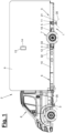
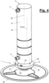
- FIG. 4 and 5 illustrate, by way of example, the structure of a fluidic, in particular hydraulic, lifting support (5).
- the lifting cylinder (15) has an extendable piston rod (19), at the free end of which a support foot (20) is arranged in a suitable manner, in particular in an articulated manner.
- the support foot (20) can, for example, have a prismatic or round plate shape.
- the lifting cylinder (15) has one or more fluid connections (17), which are arranged at a distance above one another, for example, on the jacket of the cylinder housing (16).
- the fluid connections (17) are connected in a suitable manner to a fluid supply (18), in particular a hydraulic supply.
- a fluid supply (18) in particular a hydraulic supply.
- Figures 1 to 3 As illustrated, this can be a decentralized fluid supply (18), with each lifting cylinder (15) preferably having its own fluid supply (18). This is, for example, mounted independently on the chassis (6) close to the lifting support (5).
- the jack support assembly (3) can have a controller (12) that controls the decentralized fluid supplies (18) and the fluid jack supports (5).
- the jack support assembly (3) can have a central and centrally controlled fluid supply to which all fluid jack supports (5) are connected.
- the controller (12) can have an electronic control and processing unit, data and program memory, and I/O interfaces. It can also include a leveling device (4) with a leveling sensor system and a leveling control, which controls the fluidic jacks (5) and enables leveling and alignment of the chassis (6) in a desired spatial angular position, e.g., horizontal.
- the leveling control can be integrated into the controller (12) of the jack assembly (3) as a hardware and/or software control module.
- the controller (12) can further comprise a communication means (33) for wired or preferably wireless communication to the outside, in particular to a preferably mobile operating means (13) with a display (14).
- the operating means (13) can be designed, for example, as a smartphone and can also comprise a corresponding communication means.
- Wireless communication can be effected in any manner, e.g., via Bluetooth, radio, infrared, or the like.
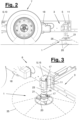
- the lighting device (1) is in Figures 2 to 9 shown in more detail. It has an annular illuminant (21) which is provided and designed for mounting on the cylinder housing (16). This particularly concerns mounting at the lower end of the cylinder housing (16). As Figures 2 and 3 To illustrate, the lower end of the cylinder housing (16) is located in the assembly position below the chassis (6) and its longitudinal members (10).
- the annular illuminant (21) is adapted to the cylindrical housing (16). It is designed and constructed for circumferential, in particular coaxial, mounting on the casing of the cylindrical housing (16).
- the illuminant (21) has a circular ring shape
- the cylindrical housing (16) has a cylindrical shape with a circular cross-section.
- other cross-sectional and ring shapes are possible.
- the annular illuminant (21) comprises an annular support (22) with a preferably annular light arrangement (30) and a fastening means (24).
- the fastening means (24) is provided and designed for a force-fitting and/or form-fitting fastening of the support (22) to the cylinder housing (16).
- the fastening means (24) is designed as a clamping device. with which the carrier (22) can be clamped circumferentially at the lower end of the cylinder housing (16).
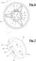
- Figures 7 to 9 illustrate an exemplary embodiment of the clamping fastening means (24). It has a slotted clamping ring (25) which is arranged in a suitable manner on the annular carrier (22).
- the slot or gap (26) can be Figure 7 extend in the axial direction (23).
- the clamping ring (25) is formed, for example, in a collar-like manner, on a front end of the, for example, cylindrical clamping ring (22), in particular by being integrally formed.
- the remaining part of the carrier (22) can be unslotted and designed with a closed circumference.
- the carrier (22) can be made of plastic, metal, or another suitable material.
- the fastening means (24) further comprises a clamping means (27) with which the slotted clamping ring (25) can be clamped and contracted in the circumferential direction.
- the clamping means (27) is, for example, according to Figure 7 designed as a tangential bore in the clamping ring (25), which extends across the gap (26) and accommodates a clamping screw or the like.
- the support (22) can be clamp-like and divided into several parts. These can be, for example, half rings that are connected to one another via a joint on one side and have a closure on the other side for mutual fixation. Furthermore, other types of multi-part and composable support designs are possible. A support design that can be clamped circumferentially and optionally axially slid onto the cylinder housing (16) is advantageous.
- the annular support (22) has a smooth wall on its inner side without radial projections for preferably full-surface contact with the jacket of the cylinder housing (16).
- the inner side of the support and the outer jacket of the cylinder housing (16) can have positively engaging projections and recesses that provide a positive connection in the direction of the common axis (23) and/or in the circumferential direction.
- the fastening means (24) are designed for a detachable fixation of the illuminant (21) to the lifting cylinder (15).
- a fixed and permanent connection and fixation can also be provided.
- the annular support (22) suitably accommodates at least one lighting arrangement (30). This can be formed from one or more individual or connected lighting elements (31), e.g., LEDs. These can be single-colored or multi-colored.
- a communication means (33) and, if appropriate, one or more additional components (36) can also be arranged on the support (22).
- the support (22) can also have a power supply (32), e.g., in the form of a replaceable and/or rechargeable battery.
- the annular support (22) has an annular lamp holder (28) on one of its axial front sides for receiving the lamp assembly (30).
- the lamp holder (28) is designed, for example, as an annular recess or groove on said front side. It can alternatively be designed and arranged in a different manner.
- the lamp assembly (30) can be designed as a closed ring or in a segmented form. Figure 5 clarified the arrangement in section.
- the annular support (22) may have an outlet (29) for a cable (34) or the like on its other axial front side.
- Figure 4 , 6 , 8 and 9 illustrate this design.
- the cable (34) can itself be a communication device (33) and establish a communication connection to the outside via which energy and/or electrical signals can be transmitted.
- the outlet (29) is e.g. according to Figure 6 arranged on the circumference offset by 90° to the fastening means (24).
- the outlet (29) can be located on the rear of the lifting cylinder (15) and on the side facing the chassis (6) or longitudinal member (10) in the assembled position of the ring-shaped lighting means (21).
- the cable (34) can thus be routed hidden on the rear of the lifting cylinder (15) to the chassis (6) and from there to the control unit (12) and/or an on-board power supply (32) of the road vehicle (2) or jack assembly (3).
- This can be, for example, the system battery of the road vehicle (2).
- the lighting arrangement (30) can also emit light transversely to the axial direction (23), e.g., in the radial direction.
- the annular support (22) can have one or more wall openings from which the lighting arrangement (30) or one or more lighting elements (31) can emit light in said transverse direction. This allows, for example, the interior of the vehicle below the chassis (6) to be specifically illuminated by horizontally or obliquely emitted light.
- the lighting arrangement (30) can produce different lighting effects. For example, it can maintain a constant light color or change it. It can emit continuous light or intermittent, particularly pulsed, light. This can be, for example, a pulsating red warning light or a continuous green light, which provides a warning signal or a positive status message.
- the lighting arrangement (30) can also emit contoured light and project it onto the surface. This can be, for example, an image or lettering, particularly a logo.
- the communication means (33) is arranged on the support (22), in particular in or on the lamp holder (28).
- the illustrated communication means (33) is wired and comprises the aforementioned cable (34).
- the communication means (33) can be wireless and can, for example, comprise a transmitting and receiving module for radio signals or the like.
- Figure 9 also illustrates the possibility of arranging one or more additional components (36) on the annular illuminant (21), in particular on the support (22).
- This can be, for example, an electronic camera or a camera eye.
- Another component (36) can be a motion detector, a light sensor, or the like.
- the lighting device (1) has a power supply (32) for the illuminant (21), which can also supply the communication means (33) and one or more possible additional components (36).
- the power supply (32) can be arranged on the illuminant (32). Alternatively, it can be arranged in the aforementioned manner on the road vehicle (2) or on the jack assembly (3) or at another location, and can supply the power via the cable (34) or in another suitable manner.
- the lighting device has a control (12) for the light source (21). This can be a separate control, which is optionally arranged on the light source (21), in particular on the support (22).
- the control (12) of the jack support arrangement (3) is used. Communication and an exchange of control and status signals as well as other data can take place via the cable (34) or wirelessly.
- the control (12) can be used to control the light arrangement (30) and possibly one or more other components (36). This control can take place as a function of signals, in particular status or control signals, from the jack support (5) or the jack support arrangement (3).
- the lighting arrangement (30) can be switched on automatically, depending on the ambient light.
- a further component (36) designed as a camera can also be switched on automatically.
- the camera images for example, captured of the ground beneath the jack (5), can be evaluated in the control system (12) to check and assess the suitability and support capacity of the ground. If the suitability is inadequate, the extension process can be stopped and a warning signal issued.
- a further component (36) designed as a motion detector can detect movements of animals or the like beneath the chassis (6) of a parked road vehicle (2) and report them to the controller (12), which then switches on the lighting means (21), in particular the lighting arrangement (30) and, if appropriate, a further component (36), e.g., a camera.
- the lighting arrangement (30) can be switched off in any suitable manner, e.g., via a preprogrammed time sequence, a detected external event, or the like.
- the lighting device (1) can have a preferably mobile and wirelessly communicating operating means (13). This can be a dedicated operating means (13). Alternatively, an existing operating means (13) of the jack assembly (3) and/or the road vehicle (2) can be used. Furthermore, it is possible to use an existing generic operating means, e.g., in the form of a smartphone. In these cases, the lighting device (1) can include a software component, e.g., an app.
- the operating means (13) can have a display (14) on which messages from the lighting device (1) and, if applicable, the jack assembly (3) as well as from the road vehicle (2) are shown.
- An operating mask can be shown on the display (14), via which inputs to the controller (12) and to the lighting device (1) are possible.
- the operating element (13) can be used, for example, to switch on the lighting means (21), in particular the lighting assembly (30), and to control it as required, e.g., to emit modulated light.
Landscapes
- Engineering & Computer Science (AREA)
- Mechanical Engineering (AREA)
- Physics & Mathematics (AREA)
- Fluid Mechanics (AREA)
- Road Signs Or Road Markings (AREA)
- Non-Portable Lighting Devices Or Systems Thereof (AREA)
- Lighting Device Outwards From Vehicle And Optical Signal (AREA)
Description
- Die Erfindung betrifft eine fluidische, insbesondere hydraulische, Hubstütze mit einer Beleuchtungseinrichtung mit den Merkmalen im Oberbegriff des Anspruchs 1.
- Ein solche hydraulische Hubstütze mit einer Beleuchtungseinrichtung ist aus der
US 2007/0013537 A1 bekannt. Die Beleuchtungseinrichtung ist als integraler Bestandteil an einem Basisteil eines Stützfußes befestigt. Die Beleuchtungseinrichtung soll beim Reifenwechseln helfen und ist in bodennaher Beleuchtungsfunktion am Stützfuß angeordnet. - Aus der
DE 10 2017 130 139 A1 ist eine andere hydraulische Hubstütze eines Straßenfahrzeugs mit einer Beleuchtungseinrichtung bekannt, welche Leuchtmittel umfasst, die beidseits des oberen Zylinderendes und von diesem rückversetzt an einem Montagebeschlag angeordnet sind, der zur Hubstützenbefestigung an einem Längsträger des Fahrzeugchassis dient. - Die
US 2020/0039477 A1 offenbart einen teleskopierbaren Elektrozylinder mit einzelnen Lichtern am oberen Zylinder, die einzeln und direkt am oberen Zylindermantel montiert sind. Die Lichter sind verteilt nur an einer Umfangsseite des Zylinders angeordnet. Sie leuchten in einem beschränkten Bereich, um einen Reifenwechsel zu erleichtern. - Aus der
GB 2 527 308 A - Es ist Aufgabe der vorliegenden Erfindung, eine fluidische, insbesondere hydraulische, Hubstütze mit einer verbesserten Beleuchtungseinrichtung aufzuzeigen.
- Die Erfindung löst diese Aufgabe mit den Merkmalen in den unabhängigen Ansprüchen.
- Die Beleuchtungseinrichtung weist ein ringförmiges Leuchtmittel auf, welches zur Montage an einem Zylindergehäuse der fluidischen, insbesondere hydraulischen Hubstütze eines Straßenfahrzeugs vorgesehen und ausgebildet ist. Besonders günstig ist hierbei die Ausbildung für eine Montage am unteren Ende des Zylindergehäuses.
- Eine Ausbildung für eine umfangseitige, bevorzugt koaxiale, Montage am Mantel des Zylindergehäuses ist vorgesehen . Das montierte ringförmige Leuchtmittel umschliesst das Zylindergehäuse umfangseitig.
- Die fluidische, insbesondere hydraulische, Hubstütze und das Zylindergehäuse können eine aufrechte, insbesondere senkrechte Lage und Ausrichtung an der Montage- oder Befestigungsstelle am Straßenfahrzeug haben.
- Die ringförmige Ausbildung des Leuchtmittels hat verschiedene Vorteile. Sie bietet eine bessere Beleuchtungswirkung und bessere Montagemöglichkeiten als beim Stand der Technik.
- Das ringförmige Leuchtmittel kann nach mehreren verschiedenen Richtungen abstrahlen. Es kann einen besonders guten und großen Leuchtkegel bilden. Der Leuchtkegel kann insbesondere nach unten strahlen. Das ringförmige Leuchtmittel kann zusätzlich oder alternativ auch nach oben strahlen.
- Die Richtungsangaben unten/oben beziehen sich auf die Anbau- oder Montagestellung am Straßenfahrzeug bzw. auf die Unterseite und Oberseite des Hubzylinders. An der Unterseite fährt bei der Hubstützenbetätigung ein Zylinderteil, insbesondere die Kolbenstange, aus.
- Das Leuchtmittel kann unter einer Befestigungsstelle am Chassis des Straßenfahrzeugs, insbesondere unter einem Längsträger, hindurch bis in den unterhalb der Fahrzeugmitte liegenden Untergrundbereich strahlen. Hierdurch kann die Beleuchtungseinrichtung einen Mehrfachnutzen erhalten. Sie kann nicht nur den Standbereich am Untergrund der Hubstütze beleuchten. Sie kann bei Dunkelheit auch das Hantieren mit einem im inneren Chassisbereich angeordneten Ersatzrad, einem Tank oder dgl. erleichtern. Eine großflächige Ausleuchtmöglichkeit des Bereichs unter dem Chassis hat zudem Sicherheitsaspekte.
- Eine Ausbildung des Leuchtmittels zur Montage am unteren Ende des Zylindergehäuses ist hierfür besonders vorteilhaft. Dieser Bereich befindet sich unterhalb des Fahrzeugchassis und ist für den weiten Strahlkegel besonders vorteilhaft. Andererseits kann das ringförmige Leuchtmittel am Zylindergehäuse, insbesondere am Umfang, formschlüssig geführt und gehalten werden. Es kann besonders sicher und positionsgenau angebracht werden. Bei der Fahrt kann ein Stützfuß am unteren Ende des eingefahrenen Zylinders das Leuchtmittel vor Umwelteinflüssen, z.B. Steinschlag, schützen. Eine Montage am unteren Ende des Zylinders ist auch hierfür von besonderem Vorteil.
- Eine Adaption des ringförmigen, insbesondere kreisringförmigen, Leuchtmittels an das bevorzugt im Querschnitt ebenfalls kreisringförmige Zylindergehäuse und eine umfangseitige koaxiale Montage am Mantel des Zylindergehäuses sind für eine einfache und sichere Montage besonders günstig. Hierbei ist eine kraftschlüssige und/oder formschlüssige Befestigung, insbesondere Klemmbefestigung, am Zylindergehäuse möglich. Ferner sind andere, z.B. ovale oder prismatische, Ring- und Querschnittsformen möglich.
- Das Leuchtmittel kann einen ringförmigen Träger mit einer bevorzugt ringförmigen Leuchtenanordnung und einem Befestigungsmittel aufweisen. Dieses kann z.B. für eine kraftschlüssige Befestigung einen bevorzugt axial geschlitzten Klemmring am ringförmigen Träger und ein Spannmittel aufweisen. Alternativ ist eine andere Ausbildung des Befestigungsmittels möglich.
- Der ringförmige Träger kann an seiner axialen Frontseite einen ringförmigen und bevorzugt vertieften Leuchtenhalter für die Aufnahme einer Leuchtenanordnung aufweisen, die z.B. von ein oder mehreren Leuchtelementen gebildet werden kann. Das oder die Leuchtelemente können vorteilhafterweise als einfarbige oder mehrfarbige LEDs ausgebildet sein.
- Die axiale Frontseite und der Leuchtenhalter können in der Montagestellung nach unten zum Stützfuß der Hubstütze gerichtet sein. An seiner anderen axialen Frontseite kann der ringförmige Träger einen Auslass für ein Kabel oder dergleichen aufweisen. Dieses kann in der Montagestellung geschützt hinter dem Zylinder nach oben zum Fahrzeugchassis geführt werden.
- Die Leuchtenanordnung kann Licht in Axialrichtung, insbesondere in Montagestellung zum Untergrund, emittieren. Die Leuchtenanordnung kann auch Licht quer zur Axialrichtung, insbesondere in Radialrichtung, emittieren. Der Träger kann hierfür z.B. ein oder mehrere Wandöffnungen mit einem entsprechenden Leuchtelement aufweisen. Hierdurch kann z.B. unter dem Chassis und parallel zu dessen Hauptebene Licht seitlich abgestrahlt werden. Dies kann an einer oder mehreren Stellen der Leuchtenanordnung und des Trägers geschehen.
- Die vor- und nachgenannte Axialausrichtungen beziehen sich auf die Längsachse des Zylinders des Leuchtmittels.
- Die Leuchtenanordnung kann verschiedenen Zwecken dienen. Sie kann einerseits in Axialrichtung des Zylinders und des ringförmigen Leuchtmittels Licht zur Beleuchtung des Stütztellers beim Ein- und Ausfahren des Zylinders und auch des Untergrunds abstrahlen. Ferner kann das Licht variiert werden. Es kann einfarbig oder mehrfarbig sein und kann auch Farbwechsel bieten. Es kann als ambientes Licht dienen, das beim Einschalten dauerhaft oder intermittierend strahlt und den Untergrund des Straßenfahrzeugs rund um die ausgefahrene Hubstütze beleuchtet. Das Licht kann andererseits als Signallicht eingesetzt werden, wobei z.B. Funktionsstörungen der Hubstütze, eine unzureichende Untergrundqualität oder dgl. durch moduliertes Licht, z.B. pulsierendes Licht in roter Farbe, signalisiert werden.
- Das Leuchtmittel kann ein oder mehrere weitere Komponenten beinhalten. Dies kann z.B. eine elektronische Kamera, ein Bewegungsmelder, ein Datenspeicher, eine Tageslicht/Dunkelheit detektierender Lichtsensor oder dgl. sein.
- Das Leuchtmittel kann ein Kommunikationsmittel aufweisen. Dieses kann drahtlos oder leitungsgebunden, z.B. als am Auslass herausgeführtes Kabel, ausgebildet sein. Über das Kommunikationsmittel können bedarfsweise Energie und/oder Signale von und nach außen übermittelt werden.
- Die Beleuchtungseinrichtung kann eine eigene Energieversorgung für das Leuchtmittel aufweisen. Diese kann z.B. im oder am Leuchtmittel angeordnet sein. Die Beleuchtungseinrichtung kann auch mit einer externen Energieversorgung, z.B. einer Boardbatterie des Straßenfahrzeugs, über das Kommunikationsmittel verbunden sein.
- Die Beleuchtungseinrichtung kann eine ggf. eigene Steuerung für das Leuchtmittel aufweisen. Diese kann im oder am Leuchtmittel angeordnet sein. Auch eine externe Anordnung der Steuerung und eine Signalverbindung über das Kommunikationsmittel sind möglich. Die Steuerung für die Beleuchtungseinrichtung kann hardwaremäßig oder softwaremäßig, z.B. als Softwaremodul, ausgebildet sein. Sie kann auch in eine andere Steuerung, z.B. die Steuerung einer Hubstütze oder einer Hubstützenanordnung, integriert sein.
- Die Energie und/oder Signale können für die Versorgung und Ansteuerung der Leuchtenanordnung und ggf. auch von einer oder mehreren weiteren Komponenten dienen. Von der Leuchtenanordnung können auf Befehl einer Steuerung der Hubstützenanordnung oder der Hubstütze optische Funktionsmeldungen, Warnsignale oder dgl. emittiert werden. Auf ein Signal des Bewegungsmelders hin kann z.B. die Leuchtenanordnung und ggf. eine Kamera eingeschaltet werden. Eine Kamera kann zur Prüfung des Untergrunds beim Ausfahren einer Hubstütze eingesetzt werden und kann ggf. zusammen mit der Leuchtenanordnung bei Vorliegen eine Ausfahrbefehls für die Hubstützenanordnung oder die Hubstütze eingeschaltet werden. Über einen Lichtsensor kann bei Einbruch der Dunkelheit automatisch die Leuchtenanordnung eingeschaltet und bei einem Aufhellen wieder ausgeschaltet werden. Darüber hinaus gibt es weitere Funktionen.
- Die Beleuchtungseinrichtung kann ein eigenes bevorzugt mobiles und drahtlos kommunizierendes Bedienmittel aufweisen. Alternativ kann ein bereits vorhandenes Bedienmittel der Hubstützenanordnung genutzt werden. Dies kann ein spezielles und adaptiertes Bedienmittel sein. Es ist außerdem möglich, eine App für ein bereits vorhandenes generisches Bedienmittel, z.B. ein Smartphone, vorzusehen. Mit dem Bedienmittel können Steuerbefehle, Zustandsmeldungen, Quittungssignale oder dgl. Daten und/oder Signale ausgetauscht werden.
- Die Hubstütze kann eine ausfahrbare Kolbenstange mit einem endseitigen und bevorzugt plattenförmigen Stützfuß aufweisen. Die Hubstütze kann eine eigene dezentrale Fluidversorgung haben. Sie kann alternativ an eine zentrale Fluidversorgung von mehreren Hubstützen, z.B. auch einer kompletten Hubstützenanordnung mit z.B. vier Hubstützen, angeschlossen sein.
- Die Erfindung betrifft auch eine Hubstützenanordnung für ein Straßenfahrzeug mit mehreren solcher fluidischen Hubstützen, die allesamt oder teilweise eine Beleuchtungseinrichtung der beanspruchten Art aufweisen. Die Hubstützenanordnung kann eine Nivelliereinrichtung aufweisen, mit der über die Hubstützen eine Nivellierung des Fahrzeugchassis auf eine gewünschte Raumlage, z.B. eine abgesenkte Horizontallage, möglich ist.
- Die Beleuchtungseinrichtung und das ringförmige Leuchtmittel können als Zubehör ausgebildet und an bestehenden Hubstützen und Hubstützenanordnungen bedarfsweise nachgerüstet werden. Die Beleuchtungseinrichtung kann auch bereits an einer Hubstütze fest verbaut sein und mit dieser zusammen ausgeliefert werden. Ferner ist es möglich, die Beleuchtungseinrichtung im Wege der Erstausrüstung an einem Straßenfahrzeug zusammen mit einer oder mehreren Hubstützen und ggf. einer Hubstützenanordnung zu montieren.
- In den Unteransprüchen sind weitere vorteilhafte Ausgestaltungen der Erfindung angegeben.
- Die beanspruchte Hubstütze und Hubstützenanordnung mit der Beleuchtungseinrichtung sowie das beanspruchte Straßenfahrzeug können folgende Ausgestaltungsmerkmale aufweisen. Diese können einzeln oder in beliebiger Kombination miteinander eingesetzt werden.
- Das ringförmige Leuchtmittel der Beleuchtungseinrichtung kann einen ringförmigen Träger aufweisen, der in der vorgenannten Weise umfangseitig am Mantel des Zylindergehäuse befestigbar oder befestigt ist.
- Der ringförmige Träger kann an seiner einen axialen Frontseite einen ringförmigen, bevorzugt vertieften, Leuchtenhalter für die Aufnahme einer bevorzugt ringförmigen Leuchtenanordnung aufweisen. Der ringförmige Träger kann an seiner anderen axialen Frontseite einen Auslass für ein Kabel oder dgl. aufweisen.
- Die bevorzugt ringförmige Leuchtenanordnung kann ein oder mehrere Leuchtelemente, insbesondere ein- oder mehrfarbige LED(s), umfassen.
- Die Beleuchtungseinrichtung, insbesondere das Leuchtmittel, kann eine oder mehrere weitere Komponenten, insbesondere eine elektronische Kamera, einen Bewegungsmelder oder dgl., umfassen.
- Die Beleuchtungseinrichtung kann eine Energieversorgung für das Leuchtmittel und ggf. weitere Komponenten aufweisen. Die Energieversorgung kann im oder am Leuchtmittel angeordnet oder extern angeordnet sein.
- Die beanspruchte Hubstütze kann die Beleuchtungseinrichtung mit einem Leuchtmittel umfassen, welches ein Kabel aufweist, das an der zum Straßenfahrzeug weisenden Rückseite der Hubstütze angeordnet ist.
- Die Hubstütze kann eine ausfahrbare Kolbenstange mit einem dortigen endseitigen Stützfuss, insbesondere einem Stützteller, aufweisen.
- Die Hubstütze kann eine eigene dezentrale Fluidversorgung aufweisen. Die Hubstütze kann auch an eine zentrale Fluidversorgung einer Hubstützenanordnung angeschlossen sein, wobei die zentrale Fluidversorgung zwei oder mehr Hubstützen mit Hydraulikfluid versorgt.
- Die beanspruchte und mit der Beleuchtungseinrichtung ausgerüstete Hubstützenanordnung kann eine Nivelliereinrichtung zum Nivellieren des Chassis des Straßenfahrzeugs umfassen.
- Das beanspruchte Straßenfahrzeug kann ein Fahrgestell oder Chassis, einen bevorzugt motorisierten Fahrzeugkopf, eine hintere Achsanordnung, ggf. einen Aufbau und eine Hubstützenanordnung mit mehrere Hubstützen und die einzeln oder mehrfach vorhandene Beleuchtungseinrichtung umfassen. Die Hubstützen können am Fahrzeugkopf, insbesondere am dortigen Einstieg einer Fahrerkabine, sowie am hinteren Bereich des Fahrgestells, insbesondere am Fahrzeugheck und/oder an deiner hinteren Achsanordnung, angeordnet sein.
- Das Straßenfahrzeug kann als Wohnmobil oder als Kastenwagen ausgebildet sein. Es kann einen Wohnaufbau und/oder Kastenaufbau haben.
- Die Erfindung ist in den Zeichnungen beispielhaft und schematisch dargestellt. Im Einzelnen zeigen:
- Figur 1:
- ein Straßenfahrzeug mit fluidischen Hubstützen und einer Beleuchtungseinrichtung in einer Seitenansicht,
- Figur 2:
- eine vergrößerte Darstellung einer am Heckbereich des Fahrzeugs angeordneten Hubstütze und Beleuchtungseinrichtung gemäß
Figur 1 , - Figur 3:
- eine perspektivische Darstellung der Anordnung von
Figur 2 , - Figur 4:
- eine perspektivische Darstellung einer fluidischen Hubstütze und einer daran montierten Beleuchtungseinrichtung,
- Figur 5:
- eine geschnitte Ansicht der Anordnung von
Figur 4 , - Figur 6:
- eine Draufsicht auf die Anordnung von
Figur 4 und5 , - Figur 7:
- eine perspektivische Ansicht eines ringförmigen Leuchtmittels mit einem Träger und einem Befestigungsmittel,
- Figur 8:
- eine andere perspektivische Ansicht des Trägers von
Figur 7 und - Figur 9:
- eine Unteransicht des ringförmigen Leuchtmittels mit dem Träger und einer darin aufgenommenen Leuchtanordnung.
- Die Erfindung betrifft eine fluidische, insbesondere hydraulische, Hubstütze (5), die mit einer Beleuchtungseinrichtung (1) ausgerüstet ist. Die Erfindung betrifft ferner eine Hubstützenanordnung (3) mit mehreren fluidischen Hubstützen (5) und mindestens einer Beleuchtungseinrichtung (1). Die Erfindung bezieht sich auch auf ein Straßenfahrzeug (2) mit mindestens einer fluidischen Hubstütze (5) und einer Beleuchtungseinrichtung (1).
-
Figur 1 zeigt in einer Seitenansicht ein Straßenfahrzeug (2) mit einer fluidischen Hubstützenanordnung (2), welche mehrere fluidische Hubstützen (5) aufweist. Mindestens einer Hubstütze (5), vorzugsweise allen Hubstützen (5), ist eine Beleuchtungseinrichtung (1) zugeordnet. - Das Straßenfahrzeug (1) ist z.B. als Kraftfahrzeug ausgebildet. Es weist ein Fahrgestell (6) mit einer hinteren Achsanordnung (7) und einem motorisierten frontseitigen Fahrzeugkopf (8) mit einer Vorderachse sowie einem Aufbau (9) auf dem Fahrgestell (6) auf. Der Aufbau (9) kann in beliebiger Weise, z.B. kastenartig ausgebildet sein. Im gezeigten Ausführungsbeispiel handelt es sich um einen Wohnaufbau, wobei das Straßenfahrzeug (2) als Wohnmobil ausgebildet ist.
- Das Fahrgestell (6) kann z.B. als Leiterrahmen ausgebildet sein und Längsträger (10) sowie ggf. Querträger aufweisen. Es kann mit dem Fahrzeugkopf (8) fest verbunden sein. Der Fahrzeugkopf (8) kann als motorisierter und bevorzugt frontgetriebener Zugkopf ausgebildet sein, wobei das Fahrgestell (6) als ggf. tiefer gelegtes Anbauchassis für die nachträgliche Montage, am Zugkopf gestaltet ist. Evtl. Höhenunterschiede zwischen Zugkopfchassis und Anbauchassis können durch einen Adapter ausgeglichen werden.
- In einer anderen Ausführung kann der Fahrzeugkopf (8) einen Motor mit Getriebe, eine Vorderachse und eine Lenkeinrichtung sowie eine Fahrerkabine aufweisen, wobei die hintere Achsanordnung (7) angetrieben ist. Die hintere Achsanordnung (7) kann eine oder mehrere Achsen, z.B. eine Tandemachse oder eine Tripleachse, aufweisen.
- In einer anderen und nicht dargestellten Ausführung kann das Straßenfahrzeug (2) als Fahrzeuganhänger, z.B. als Wohnwagen oder Caravan, ausgebildet sein. Das Fahrgestell (6) ist dann mit einer Achsanordnung (7) und einer starren oder beweglichen Deichsel ausgestattet.
- Die einen oder mehreren Hubstützen (5) sind vorzugsweise als hydraulische Hubstützen ausgebildet. Die fluidischen Hubstützen (5) weisen jeweils einen fluidischen Hubzylinder (15) mit einer zentralen Achse (23) und einem Zylindergehäuse (16) auf. Die Hubstützen sind in geeigneter Weise über einen Montagebeschlag (11) am Fahrgestell (6), z.B. seitlich an einem Längsträger (10) oder einem Heckträger des Fahrgestells oder an einer Achsanordnung (7), montiert und befestigt.
- Die Hubstützen (5) können an beiden Längsseiten des Straßenfahrzeugs (2) montiert sein. In der gezeigten Ausführungsform umfasst die Hubstützenanordnung (3) vier verteilte Hubstützen (5), wobei zwei Hubstützen (5) im Heckbereich des Fahrgestells (6) und zwei Hubstützen (5) im Frontbereich angeordnet sind. Die vorderen Hubstützen (5) können z.B. unter der Einstiegstelle am Fahrzeugkopf (8) angeordnet und montiert sein.
-
Figur 4 und5 verdeutlichen beispielhaft den Aufbau einer fluidischen, insbesondere hydraulischen, Hubstütze (5). Der Hubzylinder (15) weist eine ausfahrbare Kolbenstange (19) auf, an deren freiem Ende ein Stützfuß (20) in geeigneter Weise, insbesondere gelenkig, angeordnet ist. - Der Stützfuß (20) kann z.B. eine prismatische oder runde Plattenform haben.
- Der Hubzylinder (15) weist ein oder mehrere Fluidanschlüsse (17) auf, die z.B. am Mantel des Zylindergehäuses (16) mit Abstand übereinander angeordnet sind. Die Fluidanschlüsse (17) sind in geeigneter Weise mit einer Fluidversorgung (18), insbesondere Hydraulikversorgung, verbunden. Wie
Figur 1 bis 3 verdeutlichen, kann dies eine dezentrale Fluidversorgung (18) sein, wobei bevorzugt jeder Hubzylinder (15) eine eigene Fluidversorgung (18) aufweist. Diese ist z.B. eigenständig am Fahrgestell (6) nahe an der Hubstütze (5) montiert. - Die Hubstützenanordnung (3) kann eine Steuerung (12) aufweisen, welche die dezentralen Fluidversorgungen (18) und die fluidischen Hubstützen (5) ansteuert. In einer anderen Ausführung kann die Hubstützenanordnung (3) eine zentrale und zentral gesteuerte Fluidversorgung aufweisen, an die alle fluidischen Hubstützen (5) angeschlossen sind.
- Die Steuerung (12) kann eine elektronische Steuer- und Recheneinheit, Daten- und Programmspeicher sowie I/O-Schnittstellen aufweisen. Sie kann auch eine Nivelliereinrichtung (4) mit einer Nivelliersensorik und einer Nivelliersteuerung umfassen, welche die fluidischen Hubstützen (5) ansteuert und eine Nivellierung und Ausrichtung des Fahrgestells (6) in einer gewünschten räumlichen Winkellage, z.B. in der horizontalen, ermöglicht. Die Nivelliersteuerung kann als hardwaremäßiges und/oder softwaremäßiges Steuermodul in die Steuerung (12) der Hubstützenanordnung (3) integriert sein.
- Die Steuerung (12) kann ferner ein Kommunikationsmittel (33) für eine leitungsgebundene oder bevorzugt drahtlose Kommunikation nach außen, insbesondere zu einem vorzugsweise mobilen Bedienmittel (13) mit einem Display (14) aufweisen. Das Bedienmittel (13) kann z.B. als Smartphone ausgebildet sein und kann ebenfalls ein entsprechendes Kommunikationsmittel aufweisen. Eine drahtlose Kommunikation kann in beliebiger Weise, z.B. über Bluetooth, Funk, Infrarot oder dgl., erfolgen.
- Die Beleuchtungseinrichtung (1) ist in
Figur 2 bis 9 näher dargestellt. Sie weist ein ringförmiges Leuchtmittel (21) auf, das zur Montage am Zylindergehäuse (16) vorgesehen und ausgebildet ist. Dies betrifft insbesondere eine Montage am unteren Ende des Zylindergehäuses (16). WieFigur 2 und 3 verdeutlichen, befindet sich das untere Ende des Zylindergehäuses (16) in Montagestellung unterhalb des Fahrgestells (6) und dessen Längsträgern (10). - Das ringförmige Leuchtmittel (21) ist an das Zylindergehäuse (16) adaptiert. Es ist zur umfangsseitigen, insbesondere koaxialen, Montage am Mantel des Zylindergehäuses (16) vorgesehen und ausgebildet. In der gezeigten Ausführungsform haben das Leuchtmittel (21) eine Kreisringform und das Zylindergehäuse (16) eine zylindrische Form mit kreisförmigem Querschnitt. Alternativ sind andere Querschnitt- und Ringformen möglich.
- Das ringförmige Leuchtmittel (21) weist einen ringförmigen Träger (22) mit einer bevorzugt ringförmigen Leuchtenanordnung (30) und einem Befestigungsmittel (24) auf. Das Befestigungsmittel (24) ist für eine kraftschlüssige und/oder formschlüssige Verfestigung des Trägers (22) am Zylindergehäuse (16) vorgesehen und ausgebildet. In der gezeigten Ausführungsform ist das Befestigungsmittel (24) als Klemmeinrichtung ausgebildet, mit der der Träger (22) am unteren Ende des Zylindergehäuses (16) umfangsseitig festgeklemmt werden kann.
-
Figur 7 bis 9 verdeutlichen eine beispielhafte Ausführung des klemmenden Befestigungsmittels (24). Es weist einen geschlitzten Klemmring (25) auf, der am ringförmigen Träger (22) in geeigneter Weise angeordnet ist. Der Schlitz oder Spalt (26) kann sich gemäßFigur 7 in Axialrichtung (23) erstrecken. Der Klemmring (25) ist z.B. kragenartig an einem stirnseitigen Ende des z.B. zylindrischen Klemmrings (22) ausgebildet, insbesondere angeformt. Der restliche Teil des Trägers (22) kann ungeschlitzt und mit geschlossenem Umfang ausgebildet sein. Der Träger (22) kann aus Kunststoff, Metall oder einem anderen geeigneten Material bestehen. - Das Befestigungsmittel (24) weist ferner ein Spannmittel (27) auf, mit dem der geschlitzte Klemmring (25) in Umfangsrichtung gespannt und kontrahiert werden kann. Das Spannmittel (27) ist z.B. gemäß
Figur 7 als tangentiale Bohrung im Klemmring (25) ausgebildet, die sich über den Spalt (26) hinweg erstreckt und eine durchgesteckte Spannschraube oder dgl. aufnimmt. - In einer anderen Ausgestaltung kann der Träger (22) schellenartig ausgebildet und in mehrere Teile untergliedert sein. Dies können z.B. Halbringe sein, die an einer Seite über ein Gelenk miteinander verbunden sind und an einer anderen Seite einen Verschluss für die gegenseitige Fixierung aufweisen. Ferner sind andere Arten von mehrteiligen und zusammensetzbaren Trägerausbildungen möglich. Günstig ist eine auf dem Zylindergehäuse (16) umfangseitig spannbare und ggf. axial aufschiebbare Trägerausbildung.
- In der gezeigten Ausführungsform hat der ringförmige Träger (22) an seiner Innenseite eine glatte Wandung ohne radiale Vorsprünge zur bevorzugt vollflächigen Anlage am Mantel des Zylindergehäuse (16). In einer anderen Ausgestaltung mit einem formschlüssigen Befestigungsmittel können die Trägerinnenseite und der Außenmantel des Zylindergehäuses (16) formschlüssig ineinander greifende Vorsprünge und Vertiefungen aufweisen, die einen Formschluss in Richtung der gemeinsamen Achse (23) und/oder in Umfangsrichtung bieten.
- In den genannten Ausführungsvarianten sind die Befestigungsmittel (24) für eine lösbare Fixierung des Leuchtmittels (21) am Hubzylinder (15) ausgebildet. Alternativ kann auch eine feste und dauerhafte Verbindung und Fixierung vorgesehen sein.
- Der ringförmige Träger (22) nimmt in geeigneter Weise zumindest eine Leuchtenanordnung (30) auf. Diese kann aus ein oder mehreren einzelnen oder verbundenen Leuchtelementen (31), z.B. LEDs, gebildet sein. Diese können einfarbig oder mehrfarbig sein. Am Träger (22) können ferner ein Kommunikationsmittel (33) und ggf. ein oder mehrere weitere Komponenten (36) angeordnet sein. Der Träger (22) kann auch eine Energieversorgung (32), z.B. in Form einer wechselbaren und/oder wiederaufladbaren Batterie, aufweisen.
- In der gezeigten Ausführungsform weist der ringförmige Träger (22) an seiner einen axialen Frontseite einen ringförmigen Leuchtenhalter (28) für die Aufnahme der Leuchtenanordnung (30) auf. Der Leuchtenhalter (28) ist z.B. als ringförmige Vertiefung bzw. als Nut an der besagten Frontseite ausgebildet. Er kann alternativ in anderer Weise ausgebildet und angeordnet sein. Die Leuchtenanordnung (30) kann als geschlossener Ring oder in segmentierter Form ausgebildet sein.
Figur 5 verdeutlicht die Anordnung im Schnitt. - Der ringförmige Träger (22) kann an seiner anderen axialen Frontseite einen Auslass (29) für ein Kabel (34) oder dgl. aufweisen.
Figur 4 ,6 ,8 und 9 verdeutlichen diese Ausbildung. Das Kabel (34) kann selbst ein Kommunikationsmittel (33) sein und eine Kommunikationsverbindung nach Außen herstellen, über die Energie und/oder elektrische Signale übertragen werden können. - Der Auslass (29) ist z.B. gemäß
Figur 6 am Umfang um 90° versetzt zum Befestigungsmittel (24) angeordnet. Der Auslass (29) kann sich in Montagestellung des ringförmigen Leuchtmittels (21) an der Rückseite des Hubzylinders (15) und an der zum Fahrgestell (6) bzw. Längsträger (10) weisenden Seite befinden. Das Kabel (34) kann dadurch verborgen an der Rückseite des Hubzylinders (15) bis zum Fahrgestell (6) und dort weiter bis zur Steuerung (12) und/oder einer bordeigenen Energieversorgung (32) des Straßenfahrzeugs (2) oder Hubstützenanordnung (3) geführt werden. Dies kann z.B. die Systembatterie des Straßenfahrzeugs (2) sein. - Die Öffnung des nutenartigen Leuchtenhalters (28) und die Leuchtenanordnung (30) weisen in Längsrichtung der Achse (23) und sind in Montagestellung nach unten zum Stützfuß (20) gerichtet. Die Leuchtenanordnung (30) und die ein oder mehreren Leuchtenelemente (31) emittieren Licht mit einer Richtungskomponente in dieser Axialrichtung und schräg dazu. Hierbei kann ein Lichtkegel (35) gebildet werden, der in
Figur 1 bis 3 verdeutlicht ist. Dank der Position der Leuchtenanordnung (30) unterhalb des Fahrgestells (6) kann sich der Lichtkegel (35) unter dem Fahrgestell (6) bis in den inneren Chassisbereich erstrecken. - Die Leuchtenanordnung (30) kann außerdem Licht quer zur Axialrichtung (23), z.B. in Radialrichtung, emittieren. Hierfür kann der ringförmige Träger (22) eine oder mehrere Wandöffnungen aufweisen, aus denen die Leuchtenanordnung (30) bzw. ein oder mehrere Leuchtelemente (31) Licht in der besagten Querrichtung emittieren können. Hierdurch kann z.B. gezielt durch horizontal oder schräg emittiertes Licht der innenseitige Fahrzeugbereich unterhalb des Fahrgestells (6) ausgeleuchtet werden.
- Die Leuchtenanordnung (30) kann unterschiedliche Leuchteffekte bewirken. Sie kann z.B. die Lichtfarbe konstant halten oder wechseln. Sie kann Dauerlicht oder intermittierendes, insbesondere gepulstes, Licht emittieren. Dies kann z.B. ein pulsierendes rotes Warnlicht sein oder ein grünes Dauerlicht, mit dem ein Warnsignal oder eine positive Zustandsmeldung gegeben werden. Die Leuchtenanordnung (30) kann auch konturiertes Licht emittieren und auf den Untergrund projizieren. Dies kann z.B. ein Bild oder ein Schriftzug, insbesondere ein Logo, sein.
- In der gezeigten Ausführungsform ist das Kommunikationsmittel (33) am Träger (22), insbesondere im oder am Leuchtenhalter (28), angeordnet. Das gezeigte Kommunikationsmittel (33) ist leitungsgebunden und weist das besagte Kabel (34) auf. In einer anderen Ausführungsform kann das Kommunikationsmittel (33) drahtlos ausgebildet sein und kann z.B. eine Sende- und Empfangsmodul für Funksignale oder dgl. umfassen.
-
Figur 9 verdeutlicht außerdem die Möglichkeit, am ringförmigen Leuchtmittel (21), insbesondere am Träger (22), einen oder mehrere weitere Komponenten (36) anzuordnen. Dies kann z.B. eine elektronische Kamera oder ein Kameraauge sein. Eine andere Komponente (36) kann ein Bewegungsmelder, ein Lichtsensor oder dgl. sein. - Die Beleuchtungseinrichtung (1) weist eine Energieversorgung (32) für das Leuchtmittel (21) auf, welche auch das Kommunikationsmittel (33) und eine oder mehrere evtl. weitere Komponenten (36) versorgen kann. Die Energieversorgung (32) kann am Leuchtmittel (32) angeordnet sein. Sie kann alternativ in der vorgenannten Weise am Straßenfahrzeug (2) oder an der Hubstützenanordnung (3) oder an anderer Stelle angeordnet sein und kann die Energie über das Kabel (34) oder in anderer geeigneter Weise zuführen.
- Die Beleuchtungseinrichtung weist eine Steuerung (12) für das Leuchtmittel (21) auf. Dies kann eine eigene Steuerung sein, die ggf. am Leuchtmittel (21), insbesondere am Träger (22), angeordnet ist. In der gezeigten Ausführungsform wird die Steuerung (12) der Hubstützenanordnung (3) benutzt. Eine Kommunikation und ein Austausch von Steuerungs- und Zustandssignalen sowie anderen Daten kann leitungsgebunden über das Kabel (34) oder drahtlos erfolgen. Mit der Steuerung (12) können die Leuchtenanordnung (30) und evtl. ein oder mehrere weitere Komponenten (36) angesteuert werden. Diese Ansteuerung kann in Abhängigkeit von Signale, insbesondere Zustands- oder Steuersignalen, der Hubstütze (5) oder der Hubstützenanordnung (3) erfolgen.
- Bei einem Ausfahren der Hubstütze (5) kann z.B. automatisch und ggf. außenlichtabhängig die Leuchtenanordnung (30) eingeschaltet werden. Auch eine als Kamera ausgebildete weitere Komponente (36) kann automatisch eingeschaltet werden. Die z.B. vom Untergrund unter der Hubstütze (5) aufgenommenen Kamerabilder können in der Steuerung (12) ausgewertet werden, um die Eignung und Abstützfähigkeit des Untergrunds zu prüfen und zu bewerten. Bei ungenügender Eignung kann der Ausfahrvorgang gestoppt und ein Warnsignal abgegeben werden.
- Andererseits kann eine als Bewegungsmelder ausgebildete weitere Komponente (36) bei einem abgestellten Straßenfahrzeug (2) Bewegungen von Tieren oder dgl. unter dem Fahrgestell (6) detektieren und an die Steuerung (12) melden, die daraufhin das Leuchtmittel (21), insbesondere die Leuchtenanordnung (30) und ggf. eine weitere Komponente (36), z.B. eine Kamera, einschaltet. Ein Ausschalten der Leuchtenanordnung (30) kann in beliebig geeigneter Weise, z.B. über einen vorprogrammierten Zeitablauf, ein detektiertes äußeres Ereignis oder dgl. erfolgen.
- Die Beleuchtungseinrichtung (1) kann ein bevorzugt mobiles und drahtlos kommunizierendes Bedienmittel (13) aufweisen. Dies kann ein eigenes dediziertes Bedienmittel (13) sein. Alternativ kann ein bereits vorhandenes Bedienmittel (13) der Hubstützenanordnung (3) und/oder des Straßenfahrzeugs (2) genutzt werden. Ferner ist es möglich, ein bereits vorhandenes generisches Bedienmittel, z.B. in Form eines Smartphones, zu nutzen. Zum Umfang der Beleuchtungseinrichtung (1) kann in diesen Fällen eine Softwarekomponente, z.B. eine App, gehören.
- Das Bedienmittel (13) kann ein Display (14) aufweisen, auf dem Meldungen der Beleuchtungseinrichtung (1) und ggf. der Hubstützenanordnung (3) sowie auch des Straßenfahrzeugs (2) angezeigt werden. Auf dem Display (14) kann eine Bedienmaske angezeigt werden, über die Eingaben an die Steuerung (12) und an die Beleuchtungseinrichtung (1) möglich sind. Über das Bedienelement (13) kann z.B. das Leuchtmittel (21), insbesondere die Leuchtenanordnung (30), eingeschaltet und bedarfsweise gesteuert werden, z.B. zur Abgabe von moduliertem Licht.
- Abwandlungen der gezeigten und beschriebenen Ausführungsformen sind im Rahmen der Ansprüche in beliebiger Weise möglich. Die Merkmale der verschiedenen Ausführungsformen können miteinander kombiniert oder ausgetauscht werden.
-
- 1
- Beleuchtungseinrichtung
- 2
- Straßenfahrzeug
- 3
- Hubstützenanordnung
- 4
- Nivelliereinrichtung
- 5
- Hubstütze fluidisch
- 6
- Fahrgestell
- 7
- Achsanordnung
- 8
- Fahrzeugkopf, Zugkopf
- 9
- Aufbau
- 10
- Längsträger
- 11
- Montagebeschlag
- 12
- Steuerung
- 13
- Bedienmittel
- 14
- Display
- 15
- Hubzylinder
- 16
- Zylindergehäuse
- 17
- Fluidanschluss
- 18
- Fluidversorgung
- 19
- Kolbenstange
- 20
- Stützfuß
- 21
- Leuchtmittel, Leuchtring
- 22
- Träger, Tragring
- 23
- Achse
- 24
- Befestigungsmittel
- 25
- Klemmring
- 26
- Schlitz
- 27
- Spannmittel
- 28
- Leuchtenhalter
- 29
- Auslass
- 30
- Leuchtenanordnung
- 31
- Leuchtelement, LED
- 32
- Energieversorgung
- 33
- Kommunikationsmittel
- 34
- Kabel
- 35
- Lichtkegel
- 36
- weitere Komponente
Claims (15)
- Fluidische, insbesondere hydraulische, Hubstütze (5) für ein Straßenfahrzeug (2), wobei die Hubstütze (5) einen Hubzylinder (15) mit einer zentralen Achse (23) und einem Zylindergehäuse (16) sowie eine Beleuchtungseinrichtung (1) aufweist, dadurch
gekennzeichnet, dass die Beleuchtungseinrichtung (1) ein ringförmiges Leuchtmittel (21) aufweist, das am Zylindergehäuse (16), insbesondere am unteren Ende des Zylindergehäuses (16), und umfangseitig, insbesondere koaxial, am Mantel des Zylindergehäuses (16) angeordnet sowie bevorzugt kraftschlüssig und/oder formschlüssig befestigt ist, wobei das montierte ringförmige Leuchtmittel (21) das Zylindergehäuse (16) umfangseitig umschliesst. - Hubstütze nach Anspruch 1, dadurch
gekennzeichnet, dass das ringförmige Leuchtmittel (21) an das Zylindergehäuse (16) adaptiert ist und zur umfangseitigen, bevorzugt koaxialen, Montage am Mantel des Zylindergehäuses (16) vorgesehen und ausgebildet ist. - Hubstütze nach Anspruch 1 oder 2, dadurch
gekennzeichnet, dass das ringförmige Leuchtmittel (21) einen ringförmigen Träger (22) mit einer bevorzugt ringförmigen Leuchtenanordnung (30) und einem Befestigungsmittel (24) aufweist, welches bevorzugt für eine kraftschlüssige und/oder formschlüssige Befestigung des Trägers (22) am Zylindergehäuses (16) vorgesehen und ausgebildet ist. - Hubstütze nach Anspruch 3, dadurch
gekennzeichnet, dass der ringförmige Träger (22) an seiner einen axialen Frontseite einen ringförmigen, bevorzugt vertieften, Leuchtenhalter (28) für die Aufnahme einer bevorzugt ringförmigen Leuchtenanordnung (30) aufweist. - Hubstütze nach Anspruch 3 oder 4, dadurch
gekennzeichnet, dass das
Befestigungsmittel (24) einen geschlitzten Klemmring (25) am ringförmigen Träger (22) und ein Spannmittel (27) aufweist. - Hubstütze nach einem der vorhergehenden Ansprüche, dadurch gekennzeichnet, dass das Leuchtmittel (21) ein Kommunikationsmittel (33), insbesondere ein Kabel (34), aufweist.
- Hubstütze nach einem der vorhergehenden Ansprüche, dadurch gekennzeichnet, dass die Beleuchtungseinrichtung (1) eine Steuerung (12) für das Leuchtmittel (21) aufweist, wobei die Steuerung (12) im oder am Leuchtmittel (21) angeordnet oder extern angeordnet ist.
- Hubstütze nach einem der vorhergehenden Ansprüche, dadurch gekennzeichnet, dass die Beleuchtungseinrichtung (1) ein bevorzugt mobiles und drahtlos kommunizierendes Bedienmittel (13) oder eine App für ein Bedienmittel, insbesondere ein Smartphone, umfasst.
- Hubstütze nach einem der vorhergehenden Ansprüche, dadurch gekennzeichnet, dass das ringförmige Leuchtmittel (21) Licht in Axialrichtung (23), insbesondere in Ausfahrrichtung des Hubzylinders (15), und ggf. quer dazu, insbesondere in Radialrichtung, emittiert.
- Hubstütze nach einem der vorhergehenden Ansprüche, dadurch gekennzeichnet, dass die Hubstütze (5) eine ausfahrbare Kolbenstange (19) mit einem endseitigen und bevorzugt plattenförmigen Stützfuß (20) aufweist.
- Hubstütze nach einem der vorhergehenden Ansprüche, dadurch gekennzeichnet, dass die Hubstütze (5) einen Montagebeschlag (11) zur Montage an einem Straßenfahrzeug (2), bevorzugt an dessen Fahrgestell (6), insbesondere seitlich an einem Längsträger (10) oder an einem Heckträger des Fahrgestells oder an einer Achsanordnung (7), aufweist.
- Hubstützenanordnung für ein Straßenfahrzeug (2) mit mehreren fluidischen, insbesondere hydraulischen, Hubstützen (5), dadurch gekennzeichnet, dass die Hubstützen (5) eine Beleuchtungseinrichtung (1) mit einem ringförmigen Leuchtmittel (21) aufweisen und nach einem der Ansprüche 1 bis 11 ausgebildet sind.
- Hubstützenanordnung nach Anspruch 12, dadurch
gekennzeichnet, dass die Hubstützenanordnung (3) eine Steuerung (12) und/oder eine Energieversorgung (32) und/oder ein Bedienmittel (13) aufweist, an welche das ringförmige Leuchtmittel (21) angebunden ist. - Straßenfahrzeug, insbesondere Kraftfahrzeug, mit einer Hubstützenanordnung (3), die mehrere fluidische, insbesondere hydraulische, Hubstützen (5) umfasst, dadurch gekennzeichnet, dass die Hubstützenanordnung (3) eine oder mehrere Hubstützen (5) mit einer Beleuchtungseinrichtung (1) aufweist und nach einem der Ansprüche 12 oder 13 ausgebildet ist.
- Straßenfahrzeug nach Anspruch 14, dadurch
gekennzeichnet, dass das
Straßenfahrzeug (2) ein Fahrgestell (6), einen bevorzugt motorisierten Fahrzeugkopf (8), eine hintere Achsanordnung (7) und einen Aufbau (9) aufweist, wobei bevorzugt der Fahrzeugkopf (8) als motorisierter und frontgetriebener Zugkopf und das Fahrgestell (6) als ggf. tiefer gelegtes Anbauchassis ausgebildet sind.
Applications Claiming Priority (1)
| Application Number | Priority Date | Filing Date | Title |
|---|---|---|---|
| DE202020107117.3U DE202020107117U1 (de) | 2020-12-10 | 2020-12-10 | Beleuchtungseinrichtung |
Publications (2)
| Publication Number | Publication Date |
|---|---|
| EP4011817A1 EP4011817A1 (de) | 2022-06-15 |
| EP4011817B1 true EP4011817B1 (de) | 2025-04-09 |
Family
ID=78822051
Family Applications (1)
| Application Number | Title | Priority Date | Filing Date |
|---|---|---|---|
| EP21212489.5A Active EP4011817B1 (de) | 2020-12-10 | 2021-12-06 | Beleuchtungseinrichtung |
Country Status (2)
| Country | Link |
|---|---|
| EP (1) | EP4011817B1 (de) |
| DE (1) | DE202020107117U1 (de) |
Families Citing this family (1)
| Publication number | Priority date | Publication date | Assignee | Title |
|---|---|---|---|---|
| CN115891932A (zh) * | 2022-12-10 | 2023-04-04 | 嘉兴爱华机械股份有限公司 | 一种汽车千斤顶举顶胎器越野救援脱困装置 |
Citations (1)
| Publication number | Priority date | Publication date | Assignee | Title |
|---|---|---|---|---|
| DE202014004539U1 (de) * | 2014-05-28 | 2014-07-04 | Larry SZEIDENLEDER | LED Ringleuchte |
Family Cites Families (13)
| Publication number | Priority date | Publication date | Assignee | Title |
|---|---|---|---|---|
| JPH04138088U (ja) * | 1991-06-14 | 1992-12-24 | 株式会社タダノ | アウトリガ |
| JP2528677Y2 (ja) * | 1992-05-22 | 1997-03-12 | 新明和工業株式会社 | アウトリガ装置を備えた作業車 |
| US5723939A (en) | 1994-12-28 | 1998-03-03 | Matsushita Electronics Corporation | Circular fluorescent lamp |
| US20070013537A1 (en) * | 2005-07-15 | 2007-01-18 | Jones Robert S | Vehicle mounted jack system and methods of use |
| US7588341B2 (en) * | 2006-12-12 | 2009-09-15 | Kai Hsiang Enterprise Co Ltd. | Illuminative jack |
| DE102007024936B4 (de) * | 2007-05-29 | 2010-12-09 | Hiever Co., Ltd. | Beleuchtungskörper für einen Heber |
| KR101402881B1 (ko) * | 2012-09-27 | 2014-06-27 | 구우식 | 특수차량용 아웃트리거의 위치선정장치 |
| US20140231732A1 (en) * | 2013-02-19 | 2014-08-21 | Mindrut Peter Piuian | Hydraulic jack for vehicle |
| ES2566606T3 (es) * | 2013-05-07 | 2016-04-14 | Iveco Magirus Ag | Vehículo de servicio con un sistema de asistencia para posicionar apoyos a tierra laterales |
| GB2527308B (en) * | 2014-06-17 | 2017-03-01 | Caterpillar Inc | Light system for machine |
| US9855929B2 (en) * | 2015-12-22 | 2018-01-02 | Ortagus Bennett | Wheel changing assembly |
| EP3335948B1 (de) | 2016-12-15 | 2019-09-25 | Alois Kober GmbH | Hubstützenanordnung mit einer sicherungseinrichtung |
| US11472378B2 (en) * | 2018-08-06 | 2022-10-18 | Jonathan Hernandez | Vehicle built-in electric jack system |
-
2020
- 2020-12-10 DE DE202020107117.3U patent/DE202020107117U1/de active Active
-
2021
- 2021-12-06 EP EP21212489.5A patent/EP4011817B1/de active Active
Patent Citations (1)
| Publication number | Priority date | Publication date | Assignee | Title |
|---|---|---|---|---|
| DE202014004539U1 (de) * | 2014-05-28 | 2014-07-04 | Larry SZEIDENLEDER | LED Ringleuchte |
Also Published As
| Publication number | Publication date |
|---|---|
| DE202020107117U1 (de) | 2022-03-14 |
| EP4011817A1 (de) | 2022-06-15 |
Similar Documents
| Publication | Publication Date | Title |
|---|---|---|
| DE102020117353A1 (de) | Lastenträger | |
| EP3335949B1 (de) | Dezentrale hubstützenanordnung, betriebsverfahren, fahrgestell und strassenfahrzeug | |
| EP3498548A1 (de) | Hubstützenanordnung mit einer sicherungseinrichtung | |
| US20140246637A1 (en) | Dual wind jack | |
| DE102011080578A1 (de) | Dachgepäckträgeranordnung mit integrierter Beleuchtung | |
| EP2580151B1 (de) | Hebevorrichtung zum heben und senken von lasten, insbesondere von fahrzeugen | |
| DE202009019179U1 (de) | Hilfsantrieb | |
| EP2407414B1 (de) | Hubgerüst für ein Flurförderzeug | |
| DE202011105552U1 (de) | Anhängekupplung mit einer Sensorvorrichtung und Sensorvorrichtung dafür | |
| EP4011817B1 (de) | Beleuchtungseinrichtung | |
| EP2671757B1 (de) | Lastenträger mit einem angetriebenen lastentragteil | |
| EP1533451B1 (de) | Baueinheit bestehend aus einer Handhabe und wenigstens einer Funktionseinheit | |
| DE29712954U1 (de) | Kennzeichenschild für ein Kraftfahrzeug | |
| EP3216749A1 (de) | Flurförderzeug, insbesondere gegengewichtsgabelstapler, mit einer heckraumüberwachungseinrichtung | |
| DE202019103944U1 (de) | Lastenträger | |
| EP3569564B1 (de) | Flurförderzeug mit rundumleuchte | |
| EP3210932B1 (de) | Flurförderzeug mit beleuchtung | |
| DE202004010944U1 (de) | Flurförderzeug mit mindestens einer Arbeitsbeleuchtungsvorrichtung | |
| DE19534567A1 (de) | Hebe- und Rangiergerät für Kraftfahrzeuge und mit einer solchen Vorrichtung ausgerüstetes Kraftfahrzeug | |
| EP3512798B1 (de) | Kettenfahrzeug mit universellem kran | |
| DE102021002958A1 (de) | Digital integrierter Wagenheber mit Sicherheitsüberwachender Elektronik und zusätzlicher Beleuchtungseinrichtung für Fahrzeuge, elektronisch und/oder in Hybrid Ausführung | |
| DE3808415A1 (de) | Parkvorrichtungen fuer kraftfahrzeuge | |
| EP3186138B1 (de) | Fahrradanhänger mit integrierter beleuchtung | |
| DE102014100673A1 (de) | Fahrerkabine eines Fahrzeugs mit einer Anzeigeeinheit | |
| DE202016008626U1 (de) | Anordnung mit einem Kran |
Legal Events
| Date | Code | Title | Description |
|---|---|---|---|
| PUAI | Public reference made under article 153(3) epc to a published international application that has entered the european phase |
Free format text: ORIGINAL CODE: 0009012 |
|
| STAA | Information on the status of an ep patent application or granted ep patent |
Free format text: STATUS: THE APPLICATION HAS BEEN PUBLISHED |
|
| AK | Designated contracting states |
Kind code of ref document: A1 Designated state(s): AL AT BE BG CH CY CZ DE DK EE ES FI FR GB GR HR HU IE IS IT LI LT LU LV MC MK MT NL NO PL PT RO RS SE SI SK SM TR |
|
| STAA | Information on the status of an ep patent application or granted ep patent |
Free format text: STATUS: REQUEST FOR EXAMINATION WAS MADE |
|
| 17P | Request for examination filed |
Effective date: 20221215 |
|
| RBV | Designated contracting states (corrected) |
Designated state(s): AL AT BE BG CH CY CZ DE DK EE ES FI FR GB GR HR HU IE IS IT LI LT LU LV MC MK MT NL NO PL PT RO RS SE SI SK SM TR |
|
| STAA | Information on the status of an ep patent application or granted ep patent |
Free format text: STATUS: EXAMINATION IS IN PROGRESS |
|
| 17Q | First examination report despatched |
Effective date: 20230911 |
|
| REG | Reference to a national code |
Ref country code: DE Free format text: PREVIOUS MAIN CLASS: B66F0003280000 Ref country code: DE Ref legal event code: R079 Ref document number: 502021007156 Country of ref document: DE Free format text: PREVIOUS MAIN CLASS: B66F0003280000 Ipc: B60S0009120000 |
|
| RIC1 | Information provided on ipc code assigned before grant |
Ipc: B60Q 1/26 20060101ALI20240603BHEP Ipc: B60Q 1/24 20060101ALI20240603BHEP Ipc: B60S 9/12 20060101AFI20240603BHEP |
|
| GRAP | Despatch of communication of intention to grant a patent |
Free format text: ORIGINAL CODE: EPIDOSNIGR1 |
|
| STAA | Information on the status of an ep patent application or granted ep patent |
Free format text: STATUS: GRANT OF PATENT IS INTENDED |
|
| INTG | Intention to grant announced |
Effective date: 20241108 |
|
| GRAS | Grant fee paid |
Free format text: ORIGINAL CODE: EPIDOSNIGR3 |
|
| GRAA | (expected) grant |
Free format text: ORIGINAL CODE: 0009210 |
|
| STAA | Information on the status of an ep patent application or granted ep patent |
Free format text: STATUS: THE PATENT HAS BEEN GRANTED |
|
| AK | Designated contracting states |
Kind code of ref document: B1 Designated state(s): AL AT BE BG CH CY CZ DE DK EE ES FI FR GB GR HR HU IE IS IT LI LT LU LV MC MK MT NL NO PL PT RO RS SE SI SK SM TR |
|
| REG | Reference to a national code |
Ref country code: GB Ref legal event code: FG4D Free format text: NOT ENGLISH |
|
| REG | Reference to a national code |
Ref country code: CH Ref legal event code: EP |
|
| REG | Reference to a national code |
Ref country code: DE Ref legal event code: R096 Ref document number: 502021007156 Country of ref document: DE |
|
| REG | Reference to a national code |
Ref country code: IE Ref legal event code: FG4D Free format text: LANGUAGE OF EP DOCUMENT: GERMAN |
|
| REG | Reference to a national code |
Ref country code: NL Ref legal event code: FP |
|
| PG25 | Lapsed in a contracting state [announced via postgrant information from national office to epo] |
Ref country code: ES Free format text: LAPSE BECAUSE OF FAILURE TO SUBMIT A TRANSLATION OF THE DESCRIPTION OR TO PAY THE FEE WITHIN THE PRESCRIBED TIME-LIMIT Effective date: 20250409 Ref country code: FI Free format text: LAPSE BECAUSE OF FAILURE TO SUBMIT A TRANSLATION OF THE DESCRIPTION OR TO PAY THE FEE WITHIN THE PRESCRIBED TIME-LIMIT Effective date: 20250409 Ref country code: PT Free format text: LAPSE BECAUSE OF FAILURE TO SUBMIT A TRANSLATION OF THE DESCRIPTION OR TO PAY THE FEE WITHIN THE PRESCRIBED TIME-LIMIT Effective date: 20250811 |
|
| REG | Reference to a national code |
Ref country code: LT Ref legal event code: MG9D |
|
| PG25 | Lapsed in a contracting state [announced via postgrant information from national office to epo] |
Ref country code: GR Free format text: LAPSE BECAUSE OF FAILURE TO SUBMIT A TRANSLATION OF THE DESCRIPTION OR TO PAY THE FEE WITHIN THE PRESCRIBED TIME-LIMIT Effective date: 20250710 Ref country code: NO Free format text: LAPSE BECAUSE OF FAILURE TO SUBMIT A TRANSLATION OF THE DESCRIPTION OR TO PAY THE FEE WITHIN THE PRESCRIBED TIME-LIMIT Effective date: 20250709 |
|
| PG25 | Lapsed in a contracting state [announced via postgrant information from national office to epo] |
Ref country code: PL Free format text: LAPSE BECAUSE OF FAILURE TO SUBMIT A TRANSLATION OF THE DESCRIPTION OR TO PAY THE FEE WITHIN THE PRESCRIBED TIME-LIMIT Effective date: 20250409 |
|
| PG25 | Lapsed in a contracting state [announced via postgrant information from national office to epo] |
Ref country code: BG Free format text: LAPSE BECAUSE OF FAILURE TO SUBMIT A TRANSLATION OF THE DESCRIPTION OR TO PAY THE FEE WITHIN THE PRESCRIBED TIME-LIMIT Effective date: 20250409 |
|
| PG25 | Lapsed in a contracting state [announced via postgrant information from national office to epo] |
Ref country code: HR Free format text: LAPSE BECAUSE OF FAILURE TO SUBMIT A TRANSLATION OF THE DESCRIPTION OR TO PAY THE FEE WITHIN THE PRESCRIBED TIME-LIMIT Effective date: 20250409 |
|
| PG25 | Lapsed in a contracting state [announced via postgrant information from national office to epo] |
Ref country code: RS Free format text: LAPSE BECAUSE OF FAILURE TO SUBMIT A TRANSLATION OF THE DESCRIPTION OR TO PAY THE FEE WITHIN THE PRESCRIBED TIME-LIMIT Effective date: 20250709 |
|
| PG25 | Lapsed in a contracting state [announced via postgrant information from national office to epo] |
Ref country code: IS Free format text: LAPSE BECAUSE OF FAILURE TO SUBMIT A TRANSLATION OF THE DESCRIPTION OR TO PAY THE FEE WITHIN THE PRESCRIBED TIME-LIMIT Effective date: 20250809 |
|
| PG25 | Lapsed in a contracting state [announced via postgrant information from national office to epo] |
Ref country code: LV Free format text: LAPSE BECAUSE OF FAILURE TO SUBMIT A TRANSLATION OF THE DESCRIPTION OR TO PAY THE FEE WITHIN THE PRESCRIBED TIME-LIMIT Effective date: 20250409 |
|
| PG25 | Lapsed in a contracting state [announced via postgrant information from national office to epo] |
Ref country code: DK Free format text: LAPSE BECAUSE OF FAILURE TO SUBMIT A TRANSLATION OF THE DESCRIPTION OR TO PAY THE FEE WITHIN THE PRESCRIBED TIME-LIMIT Effective date: 20250409 Ref country code: SM Free format text: LAPSE BECAUSE OF FAILURE TO SUBMIT A TRANSLATION OF THE DESCRIPTION OR TO PAY THE FEE WITHIN THE PRESCRIBED TIME-LIMIT Effective date: 20250409 |
|
| PGFP | Annual fee paid to national office [announced via postgrant information from national office to epo] |
Ref country code: AT Payment date: 20260113 Year of fee payment: 5 |
|
| PGFP | Annual fee paid to national office [announced via postgrant information from national office to epo] |
Ref country code: NL Payment date: 20251217 Year of fee payment: 5 |
|
| PG25 | Lapsed in a contracting state [announced via postgrant information from national office to epo] |
Ref country code: CZ Free format text: LAPSE BECAUSE OF FAILURE TO SUBMIT A TRANSLATION OF THE DESCRIPTION OR TO PAY THE FEE WITHIN THE PRESCRIBED TIME-LIMIT Effective date: 20250409 |
|
| PG25 | Lapsed in a contracting state [announced via postgrant information from national office to epo] |
Ref country code: EE Free format text: LAPSE BECAUSE OF FAILURE TO SUBMIT A TRANSLATION OF THE DESCRIPTION OR TO PAY THE FEE WITHIN THE PRESCRIBED TIME-LIMIT Effective date: 20250409 |
|
| PG25 | Lapsed in a contracting state [announced via postgrant information from national office to epo] |
Ref country code: SK Free format text: LAPSE BECAUSE OF FAILURE TO SUBMIT A TRANSLATION OF THE DESCRIPTION OR TO PAY THE FEE WITHIN THE PRESCRIBED TIME-LIMIT Effective date: 20250409 Ref country code: RO Free format text: LAPSE BECAUSE OF FAILURE TO SUBMIT A TRANSLATION OF THE DESCRIPTION OR TO PAY THE FEE WITHIN THE PRESCRIBED TIME-LIMIT Effective date: 20250409 |
|
| PG25 | Lapsed in a contracting state [announced via postgrant information from national office to epo] |
Ref country code: IT Free format text: LAPSE BECAUSE OF FAILURE TO SUBMIT A TRANSLATION OF THE DESCRIPTION OR TO PAY THE FEE WITHIN THE PRESCRIBED TIME-LIMIT Effective date: 20250409 |
|
| PLBE | No opposition filed within time limit |
Free format text: ORIGINAL CODE: 0009261 |
|
| STAA | Information on the status of an ep patent application or granted ep patent |
Free format text: STATUS: NO OPPOSITION FILED WITHIN TIME LIMIT |