EP4011581B1 - 3d-druckverfahren zur herstellung eines gegenstands aus beton oder mörtel mit einer durchführung - Google Patents
3d-druckverfahren zur herstellung eines gegenstands aus beton oder mörtel mit einer durchführung Download PDFInfo
- Publication number
- EP4011581B1 EP4011581B1 EP20213675.0A EP20213675A EP4011581B1 EP 4011581 B1 EP4011581 B1 EP 4011581B1 EP 20213675 A EP20213675 A EP 20213675A EP 4011581 B1 EP4011581 B1 EP 4011581B1
- Authority
- EP
- European Patent Office
- Prior art keywords
- support structure
- concrete
- mortar
- feedthrough
- mortar compound
- Prior art date
- Legal status (The legal status is an assumption and is not a legal conclusion. Google has not performed a legal analysis and makes no representation as to the accuracy of the status listed.)
- Active
Links
Images



Classifications
-
- B—PERFORMING OPERATIONS; TRANSPORTING
- B28—WORKING CEMENT, CLAY, OR STONE
- B28B—SHAPING CLAY OR OTHER CERAMIC COMPOSITIONS; SHAPING SLAG; SHAPING MIXTURES CONTAINING CEMENTITIOUS MATERIAL, e.g. PLASTER
- B28B1/00—Producing shaped prefabricated articles from the material
- B28B1/001—Rapid manufacturing of 3D objects by additive depositing, agglomerating or laminating of material
-
- B—PERFORMING OPERATIONS; TRANSPORTING
- B28—WORKING CEMENT, CLAY, OR STONE
- B28B—SHAPING CLAY OR OTHER CERAMIC COMPOSITIONS; SHAPING SLAG; SHAPING MIXTURES CONTAINING CEMENTITIOUS MATERIAL, e.g. PLASTER
- B28B7/00—Moulds; Cores; Mandrels
- B28B7/28—Cores; Mandrels
- B28B7/30—Cores; Mandrels adjustable, collapsible, or expanding
- B28B7/32—Cores; Mandrels adjustable, collapsible, or expanding inflatable
-
- B—PERFORMING OPERATIONS; TRANSPORTING
- B28—WORKING CEMENT, CLAY, OR STONE
- B28B—SHAPING CLAY OR OTHER CERAMIC COMPOSITIONS; SHAPING SLAG; SHAPING MIXTURES CONTAINING CEMENTITIOUS MATERIAL, e.g. PLASTER
- B28B7/00—Moulds; Cores; Mandrels
- B28B7/34—Moulds, cores, or mandrels of special material, e.g. destructible materials
- B28B7/342—Moulds, cores, or mandrels of special material, e.g. destructible materials which are at least partially destroyed, e.g. broken, molten, before demoulding; Moulding surfaces or spaces shaped by, or in, the ground, or sand or soil, whether bound or not; Cores consisting at least mainly of sand or soil, whether bound or not
-
- B—PERFORMING OPERATIONS; TRANSPORTING
- B33—ADDITIVE MANUFACTURING TECHNOLOGY
- B33Y—ADDITIVE MANUFACTURING, i.e. MANUFACTURING OF THREE-DIMENSIONAL [3D] OBJECTS BY ADDITIVE DEPOSITION, ADDITIVE AGGLOMERATION OR ADDITIVE LAYERING, e.g. BY 3D PRINTING, STEREOLITHOGRAPHY OR SELECTIVE LASER SINTERING
- B33Y10/00—Processes of additive manufacturing
-
- B—PERFORMING OPERATIONS; TRANSPORTING
- B33—ADDITIVE MANUFACTURING TECHNOLOGY
- B33Y—ADDITIVE MANUFACTURING, i.e. MANUFACTURING OF THREE-DIMENSIONAL [3D] OBJECTS BY ADDITIVE DEPOSITION, ADDITIVE AGGLOMERATION OR ADDITIVE LAYERING, e.g. BY 3D PRINTING, STEREOLITHOGRAPHY OR SELECTIVE LASER SINTERING
- B33Y40/00—Auxiliary operations or equipment, e.g. for material handling
-
- B—PERFORMING OPERATIONS; TRANSPORTING
- B33—ADDITIVE MANUFACTURING TECHNOLOGY
- B33Y—ADDITIVE MANUFACTURING, i.e. MANUFACTURING OF THREE-DIMENSIONAL [3D] OBJECTS BY ADDITIVE DEPOSITION, ADDITIVE AGGLOMERATION OR ADDITIVE LAYERING, e.g. BY 3D PRINTING, STEREOLITHOGRAPHY OR SELECTIVE LASER SINTERING
- B33Y80/00—Products made by additive manufacturing
-
- E—FIXED CONSTRUCTIONS
- E04—BUILDING
- E04G—SCAFFOLDING; FORMS; SHUTTERING; BUILDING IMPLEMENTS OR AIDS, OR THEIR USE; HANDLING BUILDING MATERIALS ON THE SITE; REPAIRING, BREAKING-UP OR OTHER WORK ON EXISTING BUILDINGS
- E04G15/00—Forms or shutterings for making openings, cavities, slits, or channels
- E04G15/02—Forms or shutterings for making openings, cavities, slits, or channels for windows, doors, or the like
-
- E—FIXED CONSTRUCTIONS
- E04—BUILDING
- E04G—SCAFFOLDING; FORMS; SHUTTERING; BUILDING IMPLEMENTS OR AIDS, OR THEIR USE; HANDLING BUILDING MATERIALS ON THE SITE; REPAIRING, BREAKING-UP OR OTHER WORK ON EXISTING BUILDINGS
- E04G15/00—Forms or shutterings for making openings, cavities, slits, or channels
- E04G15/06—Forms or shutterings for making openings, cavities, slits, or channels for cavities or channels in walls of floors, e.g. for making chimneys
- E04G15/061—Non-reusable forms
-
- E—FIXED CONSTRUCTIONS
- E04—BUILDING
- E04G—SCAFFOLDING; FORMS; SHUTTERING; BUILDING IMPLEMENTS OR AIDS, OR THEIR USE; HANDLING BUILDING MATERIALS ON THE SITE; REPAIRING, BREAKING-UP OR OTHER WORK ON EXISTING BUILDINGS
- E04G15/00—Forms or shutterings for making openings, cavities, slits, or channels
- E04G15/06—Forms or shutterings for making openings, cavities, slits, or channels for cavities or channels in walls of floors, e.g. for making chimneys
- E04G15/063—Re-usable forms
- E04G15/066—Re-usable forms with fluid means to modify the section
-
- E—FIXED CONSTRUCTIONS
- E04—BUILDING
- E04B—GENERAL BUILDING CONSTRUCTIONS; WALLS, e.g. PARTITIONS; ROOFS; FLOORS; CEILINGS; INSULATION OR OTHER PROTECTION OF BUILDINGS
- E04B1/00—Constructions in general; Structures which are not restricted either to walls, e.g. partitions, or floors or ceilings or roofs
- E04B1/35—Extraordinary methods of construction, e.g. lift-slab, jack-block
- E04B1/3505—Extraordinary methods of construction, e.g. lift-slab, jack-block characterised by the in situ moulding of large parts of a structure
-
- E—FIXED CONSTRUCTIONS
- E04—BUILDING
- E04G—SCAFFOLDING; FORMS; SHUTTERING; BUILDING IMPLEMENTS OR AIDS, OR THEIR USE; HANDLING BUILDING MATERIALS ON THE SITE; REPAIRING, BREAKING-UP OR OTHER WORK ON EXISTING BUILDINGS
- E04G21/00—Preparing, conveying, or working-up building materials or building elements in situ; Other devices or measures for constructional work
- E04G21/02—Conveying or working-up concrete or similar masses able to be heaped or cast
- E04G21/04—Devices for both conveying and distributing
- E04G21/0418—Devices for both conveying and distributing with distribution hose
- E04G21/0445—Devices for both conveying and distributing with distribution hose with booms
- E04G21/0463—Devices for both conveying and distributing with distribution hose with booms with boom control mechanisms, e.g. to automate concrete distribution
Definitions
- the invention relates to a method for producing an object made of concrete or mortar using 3D printing.
- 3D printing of objects made of concrete or mortar is known per se.
- a concrete or mortar mass is applied to one another in layers in the form of sheets according to the shape of the object to be produced.
- the object is created from the raw object with the desired shape by hardening the concrete or mortar mass.
- EP1587995A2 US2015072068A1 , EP3260258A1 and EP3284879A1 referred.
- objects made of concrete or mortar can be produced with a high degree of design flexibility.
- the 3D printing process reaches its limits when objects with bushings are to be created, such as those found in concrete walls with window or door openings or bushings for cable ducts, drain pipes, water pipes or similar.
- No strips of concrete or mortar mass can be deposited above such an implementation because they require stabilization in the not yet hardened state. The stabilization is guaranteed by the underlying tracks, which are not present in the implementation.
- 3D printing plastic objects it is common to print a pillar or mesh-like support structure, but this is not possible when 3D printing objects made of concrete or mortar, as such comparatively delicate structures cannot be realized.
- a method for producing a concrete wall with a window opening using 3D printing is known.
- a support structure is used around which the concrete is printed.
- the support structure is equipped with a magnet so that it can be removed with a magnetic tool after 3D printing.
- CN106088610A a method for producing a concrete wall with a window or door opening using 3D printing is known. To create the opening, a temporary support structure made of polystyrene foam is used, around which the concrete is printed and which is then removed.
- the present invention is based on the object of providing such a method.
- the invention is based on attaching a support structure to create a feedthrough during 3D printing, which is suitable for supporting the parts of the object located above the support structure while the concrete or mortar mass is hardening.
- the support structure can be a temporary support structure, which is removed again when the concrete or mortar mass has hardened to such an extent that the area above the bushing no longer requires mechanical support.
- the support structure can also be intended to remain in the object and in turn have a lead-through which then forms the lead-through of the object.
- Elements such as cable ducts, pipes or window inserts can be integrated directly into the object during 3D printing. The method can therefore be used very flexibly, depending on the requirements of the application.
- a lower section of the object is printed.
- at least one strip of concrete or mortar mass is applied, preferably several strips are applied one on top of the other in layers, whereby said lower section is created.
- This lower section of the object is referred to as the base section in the sense of the invention.
- the upward-facing surface of the base section can be mentally divided into a lead-through area and a wall area.
- the implementation area is the area above which the object is intended to pass through.
- the wall area is the area above which concrete or mortar mass adjacent to the bushing is to be applied.
- a support structure is arranged on the implementation area.
- the support structure covers the entire implementation area.
- the feedthrough area and the support structure extend from a side surface of the object (or the base section as a part of the object that has been produced up to that point) to a further side surface, preferably to the opposite side surface of the object, so that a continuous feedthrough is created through the object.
- the support structure can also be referred to as a support element.
- the wall area adjoins the feedthrough area on one side if the feedthrough connects directly to a side surface of the object. Otherwise, the wall area is divided into two sub-areas, which are separated from each other by the lead-through area, and the wall area adjoins the lead-through area on both sides.
- at least one further strip of the concrete or mortar mass is applied to the wall area, preferably several further strips of the concrete or mortar mass are applied to one another in layers, whereby a wall section adjoining the support structure on one side or two adjoining the support structure on both sides is created Wall sections of the object are created.
- the wall sections are those sections of the object which are arranged laterally adjacent to the passage and which laterally limit it.
- the height of the wall section or sections essentially corresponds to the height of the support structure, so that the support structure and wall section(s) are essentially flush at the top.
- a fourth method step at least one further strip of the concrete or mortar mass is then applied to the wall section or sections on the one hand and the support structure on the other hand; preferably several further strips of the concrete or mortar mass are applied to one another in layers.
- the concrete or mortar mass is typically applied using a print head that includes a nozzle.
- the concrete or mortar mass is fed to this nozzle via a supply line using a pump.
- the concrete or mortar mass contains at least one aggregate, a binder and added water.
- the aggregate can be of natural or synthetic origin.
- Cement or lime is preferably used as a binding agent.
- the concrete or mortar mass can contain concrete additives and/or concrete admixtures.
- the concrete or mortar mass is flowable and can therefore be deposited by the print head. After deposition, the concrete or mortar mass begins to harden, losing its flowability as a result of chemical processes (in particular the storage of the added water as crystal water: hydration) and evaporation of added water.
- the cement paste is converted into cement stone. Curing includes in particular first the stiffening, then the solidification and then again the hardening of the concrete or mortar mass. Stiffening represents the first phase of hydration, during which the concrete or mortar mass can still be processed. During the subsequent solidification phase (setting), a significant increase in viscosity occurs. During the final phase of hardening, hydration is completed.
- Hardening in the sense of the invention therefore includes in particular the phases of stiffening and solidification, so that the raw object has lost its flowability and has sufficient stability, with no undesirable plastic deformation of the concrete or mortar mass, for example under the influence of gravity, anymore occurring .
- Concrete additives are powder or liquid additives that influence certain properties of the concrete or mortar mass.
- Mineral fine materials e.g. rock powder, fly ash, tuff, trass and/or silica dust
- organic substances e.g. synthetic resin dispersions, in particular to improve workability and adhesion
- color pigments and/or fibers in particular steel, glass or plastic fibers
- Concrete admixtures are agents dissolved or suspended in water that are added to the concrete or mortar mass in order to change its properties, for example workability, setting behavior, hardening or durability, through physical and/or chemical effects.
- concrete plasticizers for example, concrete plasticizers, flow agents, stabilizers, air entraining agents, solidification accelerators, hardening accelerators, solidification retarders, hardening retarders and/or sealants can be used as concrete additives.
- the proportion of concrete additives is preferably less than 4% by weight of the concrete or mortar mass, particularly preferably at most 4% by weight, for example from 0.2% by weight to 2% by weight.
- the nozzle can be designed as a simple tube with a constant cross-section in the direction of flow of the concrete or mortar mass, or can also have a tapering or widening cross-section.
- the outlet opening of the nozzle can be shaped in any way in order to achieve an outlet cross section that is suitable for the specific application.
- the shape of the nozzle in particular its outlet opening, is preferably adapted to the width and thickness of the web of concrete or mortar mass to be produced.
- the concrete or mortar mass is fed to the nozzle via a feed line, which in particular includes pipes and/or hose lines.
- a path is a coherent layer of concrete or mortar mass, which is created by moving the push button along the direction of movement.
- the path can be straight or have any other shape.
- the web can also form a closed shape by bringing its end back to the beginning.
- the dimension of a web in the deposition direction is referred to as the length of the web.
- the perpendicular dimension in the plane of the web is called the width of the web.
- the direction in which the webs are deposited in layers on top of each other is referred to as the growth direction in the context of the invention.
- the object is thus built up in layers using 3D printing in the growth direction “from bottom to top”.
- the dimension of a web in the growth direction (perpendicular to length and width) is referred to as the thickness of the web.
- the summed thickness of the tracks gives the height of the object.
- the width and thickness of the sheets can be adjusted in particular by the design of the nozzle, the consistency of the concrete or mortar mass and the delivery rate of the concrete or mortar mass.
- the thickness and width of all webs are preferably the same and constant. This is advantageous in terms of quick and technically simple deposition because the webs can then be created by a uniform movement of the print head without having to make adjustments to the conveying speed or nozzle shape.
- the length of all the tracks of the base section and the cover section can be constant, so that all tracks are arranged flush at their beginning and end. The same applies to the sum of the length of the tracks on the same level of the wall section or sections as well as the length of the support structure. This creates an object with a constant dimension.
- a web it is also easily possible for a web to have a shorter length than the underlying web, so that the underlying web is not completely covered by the web. So An object can be created that tapers overall or in sections from bottom to top.
- the length, width and thickness of the sheets can be freely chosen by the person skilled in the art according to the requirements of the application.
- the width is, for example, from 10 mm to 500 mm, in particular from 20 mm to 100 mm, the thickness, for example, from 5 mm to 100 mm, in particular from 10 mm to 50 mm, which can be easily produced with typical nozzles.
- the maximum achievable height of the object depends on the design of the robot and the printing bed (printing base). The maximum achievable height can be increased, for example, by mounting the print bed in a vertically movable manner and moving it downwards during printing.
- the webs are applied with an alternating deposition direction, so that successive webs are deposited with the opposite direction of movement of the print head.
- the beginning of a track therefore coincides with the end of the track below it.
- the exit of the concrete or mortar mass from the nozzle can be interrupted so that the webs are separated from one another.
- the exit of the concrete or mortar mass can also be continued, so that adjacent tracks are not separated from one another, but are connected to one another in the manner of a sweeping loop by concrete or mortar mass.
- the deposition of the webs of concrete or mortar mass is preferably carried out by means of a robot, in particular an industrial robot, which moves the print head.
- 3D printing is advantageously carried out automatically using CAD processing, with the CAD data of the object being provided to a processing machine and the processing machine using the CAD data to deposit the paths for producing the object.
- the print head is particularly preferably mounted on a robot arm.
- industrial robots can also be used that are less Have more degrees of freedom of movement than a robot arm.
- the movement of the push button is preferably computer-aided using the CAD data ( computer-aided design ).
- the paths can thus be deposited with high precision and speed and low labor intensity to create the object.
- the article (and each panel and section of the article) has an upwardly facing upper surface and a downwardly facing lower surface, and four side surfaces.
- the four side surfaces are two end surfaces and two transverse side surfaces extending between them.
- the end faces extend along the width dimension and are formed by the beginning and end of the tracks.
- the transverse side surfaces extend along the length dimension and are formed by the lateral boundaries of the tracks. Typically, the transverse side surfaces are the longer side surfaces and the end surfaces are the shorter side surfaces of the object. If the panels form a closed shape, the end faces are omitted because the end of the panels is returned to the beginning and connected to it. Since the sheets typically have rounded side edges for manufacturing reasons, the side surfaces are not flat surfaces, but rather have curvatures with incisions in between.
- the feedthrough area and the support structure arranged thereon extend from a first side surface of the object to a second side surface, so that a continuous feedthrough is created through the object.
- the feedthrough area and the support structure arranged thereon extends from one side surface to the opposite side surface, so that a straight feedthrough is created, as will be required in most applications.
- These two mutually opposite side surfaces can be the end faces of the object, so that the feedthrough area and the support structure extend longitudinally to the direction of extension of the webs, i.e. in the length dimension of the webs.
- the implementation area and the Support structures are then arranged over the entire length of the base section.
- the two opposite side surfaces can also be the transverse side surfaces of the object, so that the feedthrough area and the support structure extend transversely, in particular perpendicular to the direction of extension of the webs, i.e. in the width dimension of the webs.
- the feedthrough area and the support structure are then arranged on the base section over the entire width of the base section.
- the direction of extension of the webs corresponds to the directions of movement of the print head.
- the two said side surfaces can also be adjacent side surfaces, so that the feedthrough runs at an angle, so to speak, and the feedthrough area and the support structure extend partly longitudinally and partly transversely to the direction of extension of the webs.
- strips of concrete or mortar mass are arranged on top of one another in layers on the wall area, thereby producing the wall section or sections.
- the additional sheets of concrete or mortar mass are applied to the wall area and the support structure.
- the concrete or mortar mass is then deposited through the nozzle as well as in the base section and in the cover section and each strip covers the wall area and the support structure. It is not necessary to temporarily interrupt the supply of concrete or mortar.
- the concrete or mortar mass applied to the support structure is then removed again, so that the concrete or mortar mass remains solely on the wall area.
- the removal of the concrete or mortar mass can be done in sections, so that the concrete or mortar in one course is removed before the next course is applied. However, several or all of the tracks can also be deposited first and then removed together.
- the (still flowable) concrete or mortar mass can be removed, for example, by blowing off, filling, wiping or rinsing. It is also conceivable to provide the support structure with an inclined upper surface so that the concrete or mortar mass deposited on it slides down.
- the wall section or the wall sections are printed with a nozzle which has a reduced width compared to the nozzle for the base section and the cover section, so that paths with the width of the (respective) wall section are created.
- the shape of the support element depends on the requirements in the individual case, in particular on the purpose of the implementation created.
- the support element can, for example, have a rectangular, triangular, circular or oval cross section (perpendicular to the direction of extension of the bushing to be created).
- the support element has a flat base surface, which is arranged on the base area facing the base area, and a width that remains constant or becomes smaller as it progresses from bottom to top. This makes particularly stable wall sections possible because there are no “shaded” areas for 3D printing.
- the support structure has a rectangular cross section. Support elements with a rectangular cross section are required for most applications and can be integrated particularly well into the object with approximately cuboid tracks.
- a temporary support structure is provided, which is removed again after the cover section has been printed and the concrete or mortar mass has completely or partially hardened.
- the support structure is, so to speak, a placeholder for the desired implementation, which is created by removing the support structure.
- This embodiment is particularly suitable for producing feedthroughs transverse to the direction of extension of the tracks, because the support structures can then be removed more easily due to their smaller extent. But it can also be used to produce bushings along the direction of extension of the tracks. Before the support structure is removed, the flowability of the concrete or mortar mass must have decreased to such an extent and its dimensional stability must have increased to such an extent that the bushing remains in place without the area of the cover section arranged directly above sagging into the bushing under the influence of gravity.
- This area is sufficiently stabilized by the hardening of the concrete or mortar mass so that it no longer requires support from the support structure, which can then be removed. It is not necessary that the solidification (or even hardening) phase be completely completed. It is also sufficient if the base section, the wall section and a part of the cover section located directly above are sufficiently stabilized. Since the 3D printing of the object can take several hours depending on its size, it is possible to remove the support structure before the top panels of the cover section have hardened (if they are still flowable).
- the temporary support structure can be designed in various ways.
- the support structure is provided as a prefabricated component and placed on the feedthrough area of the base section.
- the support structure is preferably made of wood, metal (in particular foamed metals or metal alloys), ceramic or plastic (in particular foamed plastics, such as expanded polystyrene (“Styrofoam”)).
- foamed metals and foamed plastics are their low weight, which makes them...
- the base area is only lightly loaded.
- the support structure can be solid or frame-like. In the case of a frame-like support structure, a passage extends through the support structure parallel to the web planes.
- the support structure can simply be pushed out or first dismantled, for example sawed or cut, and then removed piece by piece. Removal of the support structure using cutting processes such as milling, drilling, planing or chiseling is also conceivable.
- the support structure is designed to be inflatable. It is then easy to store and can, for example, be inflated with compressed air to be used as a support structure.
- the support structure is inflated during the 3D printing of the wall sections, in particular in such a way that it is essentially flush with the last printed web at the top, so that the height of the support structure always corresponds to the current height of the wall section under construction .
- the overlying web can then be printed as a flat web and the concrete or mortar mass on the support structure can then be removed again or can slide down as the support structure is further inflated.
- the temporary support structure is created using 3D printing on the feedthrough area of the base section.
- the production of the support structure may be completed before printing of the at least one wall section begins.
- the 3D printed support structure can be made from plastic, for example.
- the support structure is particularly preferably printed from construction foam because it only forms a slight bond to the concrete or mortar mass and can be easily removed.
- the 3D printed support structure can be removed, for example, by chemical dissolution or by machining manufacturing processes such as milling, drilling, planing or chiseling.
- the separating layer prevents the formation of a bond between the concrete or mortar mass and the support structure, so that the support structure can be removed more easily.
- the separating layer can be designed, for example, as a plastic film, as a metal film, as a paper or cardboard layer or as a layer of a soap solution.
- the temporary support structure is equipped with at least one support leg.
- the at least one support leg is suitable and intended to stabilize the support structure in such a way that it can stand independently at the required height and position that it occupies on the implementation area.
- the at least one supporting leg can advantageously prevent the base section from being affected by the pressure that the support structure and the sheets of concrete or mortar mass deposited above it exert on the base section underneath as a result of gravity before it has hardened.
- the at least one supporting leg extends from the support structure to the ground or subsoil. It does not run through the base section, but is arranged laterally thereto (runs laterally past the base area), in particular in front of one of the side surfaces between which the feedthrough area with the support structure runs.
- the support leg is particularly advantageous for support structures that are provided as prefabricated components, since these typically have a comparatively high weight.
- the support structure can already be equipped with the at least one support leg when it is arranged on the implementation area.
- the support leg can also be attached later.
- inflatable support elements can also be supported with separate legs. It is also possible to provide a 3D printed support element with legs. The legs can either be attached subsequently or provided beforehand so that the subsequently printed support structure is connected to them.
- the support structure is equipped with exactly one supporting leg, which runs past the base area on one side, or with several supporting legs, which run past the base area on one side (all supporting legs are therefore arranged in front of the same side surface of the base area).
- the advantage of this variant is that the support structure including the support leg(s) can be easily removed after the concrete or mortar has hardened, without having to dismantle at least one support leg.
- the at least one support leg can be formed in one piece with the support structure, or can be connected to the support structure via a detachable connection, for example a screw connection.
- the support structure is equipped with at least two legs, which run past the base area on both sides. At least one support leg is therefore arranged in front of each of the side surfaces, between which the feedthrough area with the support structure runs. It is sufficient if there is exactly one support leg on each side. These legs should then be equipped with a base that is sufficiently wide and heavy or weighted with a separate weight so that the support structure with the two legs can stand freely.
- the support structure is equipped with at least three legs. The three legs ensure sufficient stability without the need for special feet. At least one support leg is then arranged in front of one side surface of the base area and at least two in front of the other side surface.
- the support structure is equipped with at least four legs, with at least two legs being arranged in front of one side surface of the base area and at least two in front of the other side surface. At least the support leg or legs in front of one of the two side surfaces of the base area should be attached to the support structure with a releasable connection, for example a screw connection, so that they can be easily dismantled after the concrete or mortar mass has hardened in order to remove the support structure . Alternatively, it is also conceivable to pivotally attach the legs to the support structure so that they can be folded up to remove the support structure.
- a permanent support structure which remains permanently in the object.
- the support structure has a feedthrough which forms the feedthrough of the object.
- the permanent support structure can, for example, be made of wood, metal, plastic, ceramic or also concrete or mortar.
- the component for which the implementation is intended is preferred as a permanent support structure directly during 3D printing Object integrated.
- the permanent support structure can be, for example, a cable duct, a pipeline, a door frame or a window frame, in particular a window frame.
- the support structure can be made in one piece or in several parts.
- the support structure is formed in several parts from several sections, which are arranged one after the other on the feedthrough area. Each section is arranged on an area of the implementation area so that the adjacent sections have direct contact with one another.
- This design is particularly suitable in the event that the implementation area runs along the direction of extension of the concrete or mortar sheets, especially if prefabricated components are used as a temporary or permanent support structure. Since comparatively long support structures are typically required in this case, it may be easier to assemble them from several sections instead of using a one-piece support element.
- the sections are each arranged directly adjacent to one another, starting from one side edge of the object (or the base section), until the other side edge is reached.
- the design can also be used to produce bushings along the direction of extension of the tracks.
- the arranging of the sections of the support structure is preferably carried out automatically, in particular by means of a (further) robot which can grab and place the sections.
- the movement is preferably computer-aided using CAD data (CNC, Computerized Numerical Control ). Alternatively, you can also store the sections manually.
- the support structure is suitable for accelerating the hardening of the surrounding concrete or mortar mass. This is particularly advantageous for temporary support structures because they can then be removed more quickly because the required stability of the surrounding areas is achieved more quickly.
- the support structure is a prefabricated component equipped with a heating device in order to heat the concrete or mortar mass and thereby accelerate hardening.
- a support structure as a prefabricated component or as a 3D printed structure secretes chemicals that accelerate curing.
- a permanent support structure is equipped with a heating device arranged in the bushing during curing.
- the concrete or mortar object produced according to the invention can be used as part of the masonry of a building.
- the feedthrough is preferably a window or door opening or intended for a (in the case of temporary support elements) or as a (in the case of permanent support elements) cable duct or a pipeline.
- the invention is explained in more detail below using a drawing and exemplary embodiments.
- the drawing is a schematic representation and not to scale. The drawing does not limit the invention in any way.
- Figure 1 shows a side view of the 3D printing of an object made of concrete or mortar, the already created sections of which can be seen in cross section.
- a concrete or mortar mass 1 in the form of sheets 2 is stacked on top of one another in layers.
- the concrete or mortar mass 1 is applied by means of a print head 3, which is attached to a robot arm 7 and is moved with the associated robot.
- the print head 3 contains a nozzle 4, which is, for example, a steel tube with a suitably shaped Exit opening is formed.
- a supply line 6 is connected to the nozzle 4, via which the concrete or mortar mass 1 is supplied to the nozzle 4 by means of a pump (not shown).
- the print head 3 is moved along the pre-calculated shape of the webs 2 with the aid of a computer based on CAD data, with concrete or mortar mass 1 emerging from the nozzle 4 and forming the webs 2.
- the direction of movement R of the print head 3 is indicated by a gray block arrow.
- the thickness of the sheets 2 is, for example, 2 cm.
- Figure 1a shows the process during the deposition of the first (lowest) web 2.
- a further web 2 is then deposited onto this ( Figure 1b ).
- the direction of movement R of the print head 3 is opposite to that of the first web 2 during the deposition of the second web 2.
- the procedure continues ( Figure 1c ), whereby the webs 2 are stacked on top of each other with alternating directions of movement R in the growth direction A (also indicated by a gray block arrow) until the object has reached the desired height.
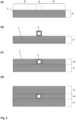
- Figure 2 shows a cross section of an object at different times of its manufacture in one embodiment of a method.
- a lower base section S is created ( Figure 2a ).
- the upper surface of the top strip 2 of the base section 2 can be mentally divided into a lead-through area B and a wall area B' arranged on both sides of it.
- the final object should have a lead-through directly above the lead-through area B and two wall sections delimiting this lead-through should be printed directly above the wall area B'.
- a support structure 5 is arranged on the implementation area B ( Figure 2b ). Two wall sections W are then printed adjacent to the support structure 5 ( Figure 2c ).
- a complete web 2 is then printed, which covers the wall area B 'and the support structure 5, and the area of this web 2 arranged on the support structure 5 is removed again, so that the concrete or mortar mass 1 remains exclusively on the wall area B' .
- the wall sections W are completed when they have reached the height of the support structure 5.
- a cover section D is then printed above the wall sections W and the support structure 5 ( Figure 2d ).
- Figure 3 shows an object G using the method Figure 2 was produced.
- the support structure 5 was intended to remain in the object G. It has a continuous passage, which then forms the passage O through the object G.
- the support structure 5 can be, for example, a cable duct or a window frame that is integrated directly into the object G during 3D printing.
- Figure 4 shows another object G, which uses the method Figure 2 was produced.
- the support structure 5 was only provided temporarily in order to stabilize the parts of the deck section D located above. After the concrete or mortar mass 1 had hardened, the support structure 5 was removed again.
- the support structure 5 can, for example, be made of wood or metal in a frame-like manner and can be pushed out of the object G after it has hardened, whereby a passage O is created through the object G.
- a cable duct or a window frame for example, can later be inserted into this bushing O.
- Figure 5 shows three views of a base area S with a support structure 5 arranged thereon in an embodiment of a manufacturing method. Show it Figure 5a a side view with a view of the transverse side surface, Figure 5b a side view with a view of the front surface and Figure 5c a top view (“view from above”).
- the implementation area B and the support structure 5 arranged thereon extend from one transverse side surface to the opposite transverse side surface. This creates a feedthrough O along the width dimension of the webs 2 or the object G, as also shown in Figure 2 is shown.
- Figure 6 shows three views of a base area S with a support structure 5 arranged thereon in a further embodiment of the method. Show it Figure 6a a side view with a view of the transverse side surface, Figure 6b a side view with a view of the front surface and Figure 6c a top view (“view from above”).
- the implementation area B and the support structure 5 arranged thereon extend from one end face to the opposite end face. This creates a feedthrough O along the length dimension of the tracks 2 or the object G.
- the support structure 5 is formed in several parts from several sections 5 '. The sections 5' were arranged one after the other on the implementation area B, with each section 5' being placed directly adjacent to the previous section 5' by means of a robot, starting from one end face.
- the support structure 5 on the implementation area B borders directly on a transverse side surface, so that the wall area B 'adjoins the lead-through area B on only one side.
- the bushing O created by means of the support structure 5 can, for example, be provided as or for a cable duct, which is then accessible via the transverse side surface to which the bushing area B adjoins. It is therefore possible to either use a temporary support structure 5 to create the bushing O, into which the cable duct is later inserted, or to integrate the cable duct as a permanent support structure 5 directly during 3D printing.
- Figure 7 shows cross sections of an object G during the printing of the wall sections W.
- the support structure 5 is inflatable and is inflated during the printing of the wall sections W by introducing compressed air.
- the support structure 5 is flush with the last printed web 2 at the top, so that a substantially flat basis for printing the next web 2 is provided.
- Figure 8 shows a cross section of a base area S with a support structure 5 arranged thereon in a further embodiment of the method.
- the support structure is made of construction foam, which was created on the implementation area B using 3D printing after the base area was completed.
- the support structure 5 can be easily removed after completion of the wall areas W and the deck area D and after the concrete or mortar mass 1 has hardened, for example mechanically or chemically.
- Figure 9 shows an exemplary embodiment of the method using a flowchart.
- Figure 10 shows two views of a base area S with a support structure 5 arranged thereon in a further embodiment of the method. Show it Figure 5a a side view with a view of the transverse side surface and Figure 5b a side view with a view of the front surface. It is a further development of the execution Figure 5 .
- the implementation area B and the support structure 5 arranged thereon extend from one transverse side surface to the opposite transverse side surface.
- the support structure 5 is equipped with a single support leg 8, which extends from the support structure 5 to the ground and runs laterally past the base area.
- the support structure 5 with the support leg 8 can stand freely, so that the support structure in the required height.
- the gravity of the support structure 5 and the tracks of the cover area D later deposited above it is absorbed by the support leg 8, so that no pressure is exerted on the base area S underneath. This prevents the base area S from being deformed before the concrete or mortar mass 1 has hardened.
- the support leg 8 attached on one side, the support structure 5 can be easily removed after the concrete or mortar mass 1 has hardened.
- the supporting leg 8 is designed to be wide and is provided with a base which is weighted down with an additional weight 9.
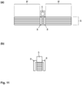
- Figure 11 shows two views of a base area S with a support structure 5 arranged thereon in a further embodiment of the method. Show it Figure 5a a side view with a view of the transverse side surface and Figure 5b a side view with a view of the front surface. It is a further development of the execution Figure 5 .
- the implementation area B and the support structure 5 arranged thereon extend from one transverse side surface to the opposite transverse side surface.
- the support structure 5 is equipped with four legs 8, which extend from the support structure 5 to the ground.
- Two legs 8 are arranged on each side of the base area S (in front of each of the two transverse side surfaces).
- the four legs 8 ensure sufficient stability without the need for weighted feet.
- At least the two supporting legs 8 on one of the two sides of the base area S are, for example, screwed to the support structure, so that they can be easily dismantled after the concrete or mortar mass 1 has hardened in order to remove the support structure 5.
Landscapes
- Engineering & Computer Science (AREA)
- Chemical & Material Sciences (AREA)
- Manufacturing & Machinery (AREA)
- Mechanical Engineering (AREA)
- Architecture (AREA)
- Materials Engineering (AREA)
- Ceramic Engineering (AREA)
- Civil Engineering (AREA)
- Structural Engineering (AREA)
- Devices For Post-Treatments, Processing, Supply, Discharge, And Other Processes (AREA)
- Producing Shaped Articles From Materials (AREA)
Description
- Die Erfindung betrifft ein Verfahren zur Herstellung eines Gegenstands aus Beton oder Mörtel mittels 3D-Druck.
- Der 3D-Druck von Gegenständen aus Beton oder Mörtel ist an sich bekannt. Dabei wird eine Beton- oder Mörtelmasse entsprechend der Form des zu erzeugenden Gegenstands in Form von Bahnen schichtweise aufeinander aufgebracht. Aus dem zu erzeugten Rohgegenstand mit der gewünschten Form entsteht der Gegenstand durch Aushärten der Beton- oder Mörtelmasse. Lediglich beispielhaft sei auf
EP1587995A2 ,US2015072068A1 ,EP3260258A1 undEP3284879A1 verwiesen. - Mittels 3D-Druck sind Gegenstände aus Beton oder Mörtel mit hoher gestalterischer Flexibilität herstellbar. Das 3D-Druckverfahren gelangt jedoch dann an seine Grenzen, wenn Gegenstände mit Durchführungen erzeugt werden sollen, wie sie beispielsweise bei Betonwänden mit Fenster- oder Türöffnungen oder Durchführungen für Kabelkanäle, Abflussrohre, Wasserleitungen oder ähnliches auftreten. Oberhalb einer solchen Durchführung können keine Bahnen der Beton- oder Mörtelmasse abgeschieden werden, weil diese im noch nicht ausgehärteten Zustand einer Stabilisierung bedürfen. Die Stabilisierung wird durch die darunterliegenden Bahnen gewährleistet, welche im Falle der Durchführung nicht vorhanden sind. Beim 3D-Druck von Kunststoffgegenständen ist es in solchen Fällen üblich, eine pfeiler- oder geflechtartige Stützstruktur zu drucken, was beim 3D-Druck von Gegenständen aus Beton oder Mörtel jedoch nicht möglich ist, da solche vergleichsweise filigranen Strukturen nicht realisierbar sind.
- Aus
CN209011362U undFR 3073170A1 - Aus
CN209211695U ist ein Verfahren zur Herstellung einer Betonwand mit einer Fensteröffnung mittels 3D-Druck bekannt. Zur Erzeugung der Fensteröffnung wird eine Stützstruktur eingesetzt, um welche der Beton herum gedruckt wird. Die Stützstruktur ist mit einem Magneten ausgestattet, um sie im Anschluss an den 3D-Druck mit einem magnetischen Werkzeug entnehmen zu können. - Aus
CN106088610A ist ein Verfahren zur Herstellung einer Betonwand mit einer Fenster- oder Türöffnung mittels 3D-Druck bekannt. Zur Erzeugung der Öffnung wird eine temporäre Stützstruktur aus Polystyrol-Schaum eingesetzt, um welche der Beton herum gedruckt wird und welche anschließend abgetragen wird. - Es besteht Bedarf an verbesserten Verfahren zum 3D-Druck von Gegenständen aus Beton oder Mörtel, welche die Herstellung eines Gegenstands mit einer Durchführung ermöglichen. Der vorliegenden Erfindung liegt die Aufgabe zugrunde, ein solches Verfahren bereitzustellen.
- Die Aufgabe der Erfindung wird erfindungsgemäß gelöst durch ein Verfahren gemäß dem unabhängigen Anspruch 1. Bevorzugte Ausführungen gehen aus den abhängigen Ansprüchen hervor.
- Beim 3D-Druck von Gegenständen aus Beton oder Mörtel werden Bahnen einer Beton- oder Mörtelmasse schichtweise aufeinander aufgebracht. Die Erfindung beruht darauf, zur Erzeugung einer Durchführung während des 3D-Drucks eine Stützstruktur anzubringen, die geeignet ist, die oberhalb der Stützstruktur befindlichen Teile des Gegenstands während des Aushärtens der Beton- oder Mörtelmasse abzustützen. Die Stützstruktur kann eine temporäre Stützstruktur sein, welche wieder entfernt wird, wenn die Beton- oder Mörtelmasse soweit ausgehärtet ist, dass der Bereich oberhalb der Durchführung keiner mechanischen Abstützung mehr bedarf. Die Stützstruktur kann aber auch dafür vorgesehen sein, im Gegenstand zu verbleiben, und ihrerseits eine Durchführung aufweisen, welche dann die Durchführung des Gegenstands bildet. So können Elemente wie Kabelkanäle, Rohrleitungen oder Fenstereinsätze direkt während des 3D-Drucks im Gegenstand integriert werden. Das Verfahren ist also, den Erfordernissen im Anwendungsfall entsprechend, sehr flexibel anwendbar. Das sind große Vorteile der vorliegenden Erfindung.
- In einem ersten Verfahrensschritt des erfindungsgemäßen Verfahrens zur Herstellung eines Gegenstands aus Beton oder Mörtel mittels 3D-Druck wird ein unterer Abschnitt des Gegenstands gedruckt. Dazu wird zumindest eine Bahn einer Beton- oder Mörtelmasse aufgebracht, bevorzugt werden mehrere Bahnen schichtweise aufeinander aufgebracht, wodurch der besagte untere Abschnitt erzeugt wird. Dieser untere Abschnitt des Gegenstands wird im Sinne der Erfindung als Sockelabschnitt bezeichnet.
- Die nach oben weisende Oberfläche des Sockelabschnitts (beziehungsweise der obersten Bahn des Sockelabschnitts) kann gedanklich in einen Durchführungsbereich und einen Wandbereich aufgeteilt werden. Der Durchführungsbereich ist derjenige Bereich, oberhalb dessen eine Durchführung durch den Gegenstand vorgesehen ist. Der Wandbereich ist derjenige Bereich, oberhalb dessen an die Durchführung grenzende Beton- oder Mörtelmasse aufgebracht werden soll. Auf dem Durchführungsbereich wird in einem zweiten Verfahrensschritt eine Stützstruktur angeordnet. Die Stützstruktur deckt den gesamten Durchführungsbereich ab. Der Durchführungsbereich und die Stützstruktur erstrecken sich von einer Seitenfläche des Gegenstands (beziehungsweise des Sockelabschnitts als bis dahin erzeugter Teil des Gegenstands) bis zu einer weiteren Seitenfläche, bevorzugt bis zur gegenüberliegenden Seitenfläche des Gegenstands, damit eine durchgehende Durchführung durch den Gegenstand erzeugt wird. Die Stützstruktur kann auch als Stützelement bezeichnet werden.
- Der Wandbereich grenzt einseitig an den Durchführungsbereich an, wenn die Durchführung direkt an eine Seitenfläche des Gegenstands anschließt. Andernfalls ist der Wandbereich in zwei Unterbereiche aufgeteilt, die durch den Durchführungsbereich voneinander getrennt sind, und der Wandbereich grenzt beidseitig an den Durchführungsbereich an. Auf den Wandbereich wird in einem dritten Verfahrensschritt mindestens eine weitere Bahn der Beton- oder Mörtelmasse aufgebracht, bevorzugt werden mehrere weitere Bahnen der Beton- oder Mörtelmasse schichtweise aufeinander aufgebracht, wodurch ein einseitig an die Stützstruktur angrenzender Wandabschnitt erzeugt wird oder zwei beidseitig an die Stützstruktur angrenzende Wandabschnitte des Gegenstands erzeugt werden. Die Wandabschnitte sind im Sinne der Erfindung diejenigen Abschnitte des Gegenstands, die seitlich benachbart zur Durchführung angeordnet sind und diese seitlich begrenzen. Die Höhe des Wandabschnitts oder der Wandabschnitte entspricht im Wesentlichen der Höhe der Stützstruktur, so dass Stützstruktur und Wandabschnitt(e) oben im Wesentlichen bündig sind.
- In einem vierten Verfahrensschritt wird anschließend mindestens eine weitere Bahn der Beton- oder Mörtelmasse auf den Wandabschnitt beziehungsweise die Wandabschnitte einerseits und die Stützstruktur andererseits aufgebracht, bevorzugt werden mehrere weitere Bahnen der Beton- oder Mörtelmasse schichtweise aufeinander aufgebracht. Dadurch wird ein oberhalb der Wandabschnitte und der Durchführung befindlicher Abschnitt des Gegenstands erzeugt, der im Sinne der Erfindung als Deckabschnitt bezeichnet wird.
- Die Beton- oder Mörtelmasse wird typischerweise mittels eines Druckkopfs aufgebracht, der eine Düse umfasst. Dieser Düse wird die Beton- oder Mörtelmasse mittels einer Pumpe über eine Zuleitung zugeführt.
- Die Beton- oder Mörtelmasse enthält zumindest eine Gesteinskörnung, ein Bindemittel und Zugabewasser. Die Gesteinskörnung kann natürlichen oder synthetischen Ursprungs sein. Als Bindemittel wird bevorzugt Zement oder Kalk eingesetzt. Optional kann die Beton- oder Mörtelmasse Betonzusatzstoffe und/oder Betonzusatzmittel enthalten. Die Beton- oder Mörtelmasse ist fließfähig und kann somit durch den Druckkopf abgeschieden werden. Nach der Abscheidung beginnt die Beton- oder Mörtelmasse auszuhärten, wobei sie ihre Fließfähigkeit infolge chemischer Prozesse (insbesondere der Einlagerung des Zugabewassers als Kristallwasser: Hydratation) und Verdunstung von Zugabewasser verliert. Dabei wird der Zementleim zu Zementstein umgewandelt. Das Aushärten umfasst insbesondere zunächst das Ansteifen, anschließend das Erstarren und wiederum anschließend das Erhärten der Beton- oder Mörtelmasse. Das Ansteifen stellt die erste Phase der Hydratation dar, wobei die Beton- oder Mörtelmasse noch verarbeitet werden kann. Während der daran anschließenden Phase des Erstarrens (Abbindens) tritt eine signifikante Viskositätszunahme auf. Während der letzten Phase des Erhärtens wird die Hydratation vervollständigt.
- Das vollständige Erhärten kann mehrere Monate in Anspruch nehmen. Es ist nicht notwendig, die gesamte Phase des Erhärtens abzuwarten, bevor die Stützstruktur entfernt werden kann, falls eine solche Entfernung vorgesehen ist. Das Aushärten im Sinne der Erfindung umfasst daher insbesondere die Phasen des Ansteifens und Erstarrens, so dass der Rohgegenstand seine Fließfähigkeit verloren hat und eine hinreichende Stabilität aufweist, wobei keine unerwünschte plastische Verformung der Beton- oder Mörtelmasse, beispielsweise unter dem Einfluss der Schwerkraft, mehr auftritt.
- Betonzusatzstoffe sind pulverförmige oder flüssige Zusätze, die bestimmte Eigenschaften der Beton- oder Mörtelmasse beeinflussen. Als Betonzusatzstoffe können mineralische Feinstoffe (beispielsweise Gesteinsmehl, Flugasche, Tuff, Trass und/oder Silicastaub), organische Stoffe (beispielsweise Kunstharzdispersionen, insbesondere zur Verbesserung von Verarbeitbarkeit und Haftung), Farbpigmente und/oder Fasers (insbesondere Stahl-, Glas- oder Kunststofffasern) eingesetzt werden. Betonzusatzmittel sind in Wasser gelöste oder aufgeschlämmte Mittel, die der Beton- oder Mörtelmasse beigemischt werden, um ihre Eigenschaften, beispielsweise Verarbeitbarkeit, Abbindeverhalten, Erhärten oder Dauerhaftigkeit, durch physikalische und/oder chemische Wirkungen zu verändern. Als Betonzusatzmittel können beispielsweise Betonverflüssiger, Fließmittel, Stabilisierer, Luftporenbildner, Erstarrungsbeschleuniger, Erhärtungsbeschleuniger, Erstarrungsverzögerer, Erhärtungsverzögerer und/oder Dichtungsmittel eingesetzt werden. Der Anteil an Betonzusatzmitteln beträgt bevorzugt weniger als 4 Gew.-% der Beton- oder Mörtelmasse, besonders bevorzugt höchstens 4 Gew.-%, beispielsweise von 0,2 Gew.-% bis 2 Gew.-%.
- Die Düse kann als einfaches Rohr mit in Fließrichtung der Beton- oder Mörtelmasse konstantem Querschnitt ausgebildet sein, oder auch einen sich verjüngenden oder erweiternden Querschnitt aufweisen. Die Austrittsöffnung der Düse kann beliebig geformt sein, um einen im konkreten Anwendungsfall geeigneten Austrittsquerschnitt zu erreichen.
- Die Form der Düse, insbesondere ihrer Austrittsöffnung, ist bevorzugt an die Breite und Dicke der zu erzeugenden Bahn an Beton- oder Mörtelmasse angepasst. Die Beton- oder Mörtelmasse wird der Düse über eine Zuleitung zugeführt, welche insbesondere Rohr- und/oder Schlauchleitungen umfasst.
- Während des Abscheidens einer Bahn der Beton- oder Mörtelmasse wird der Druckkopf in eine Richtung bewegt, welche im Sinne der Erfindung als Bewegungsrichtung des Druckkopfes oder Abscheiderichtung bezeichnet wird. Eine Bahn ist eine in sich zusammenhängende Schicht der Beton- oder Mörtelmasse, welche durch die Bewegung des Druckknopfes entlang der Bewegungsrichtung erzeugt wird. Die Bahn kann gerade sein oder auch jede beliebige andere Form aufweisen. Die Bahn kann auch eine geschlossene Form bilden, indem ihr Ende wieder zum Anfang zurückgeführt wird. Die Dimension einer Bahn in Abscheiderichtung wird im Sinne der Erfindung als Länge der Bahn bezeichnet. Die dazu senkrechte Dimension in der Ebene der Bahn wird als Breite der Bahn bezeichnet. Nachdem eine Bahn erzeugt wurde, wird die nächste Bahn als Schicht oberhalb dieser Bahn abgeschieden. Die Richtung, in der die Bahnen schichtweise übereinander abgeschieden werden, wird im Sinne der Erfindung als Aufwuchsrichtung bezeichnet. Der Gegenstand wird somit durch den 3D-Druck in Aufwuchsrichtung "von unten nach oben" schichtweise aufgebaut. Die Dimension einer Bahn in Aufwuchsrichtung (senkrecht zu Länge und Breite) wird im Sinne der Erfindung als Dicke der Bahn bezeichnet. Die summierte Dicke der Bahnen ergibt die Höhe des Gegenstands.
- Die Breite und Dicke der Bahnen kann insbesondere durch die Gestaltung der Düse, die Konsistenz der Beton- oder Mörtelmasse sowie die Förderrate der Beton- oder Mörtelmasse eingestellt werden. Die Dicke und die Breite aller Bahnen sind bevorzugt gleich und konstant. Das ist vorteilhaft hinsichtlich einer schnellen und technisch einfachen Abscheidung, weil die Bahnen dann durch eine gleichmäßige Bewegung des Druckkopfes erzeugt werden können, ohne währenddessen Einstellungen an Fördergeschwindigkeit oder Düsenform vornehmen zu müssen. Die Länge aller Bahnen des Sockelabschnitts und des Deckabschnitts kann konstant sein, so dass alle Bahnen an ihrem Anfang und ihrem Ende bündig angeordnet sind. Selbiges gilt für die Summe der Länge der Bahnen derselben Ebene des Wandabschnitts beziehungsweise der Wandabschnitte sowie der Länge der Stützstruktur. So wird ein Gegenstand mit konstanter Abmessung erzeugt. Es ist aber auch problemlos möglich, dass eine Bahn eine geringere Länge aufweist als die darunterliegende Bahn, so dass die darunterliegende Bahn nicht vollständig mit der Bahn bedeckt wird. So kann ein Gegenstand erzeugt werden, der sich insgesamt oder abschnittsweise von unten nach oben verjüngt. Die Länge, Breite und Dicke der Bahnen kann vom Fachmann den Erfordernissen des Anwendungsfalls entsprechend frei gewählt werden. Die Breite beträgt beispielsweise von 10 mm bis 500 mm, insbesondere von 20 mm bis 100 mm, die Dicke beispielsweise von 5 mm bis 100 mm, insbesondere von 10 mm bis 50 mm, was mit typischen Düsen problemlos herstellbar ist. Die maximal erreichbare Höhe des Gegenstands ist abhängig von der Konstruktion des Roboters und des Druckbettes (Druckunterlage). Die maximal erreichbare Höhe kann beispielsweise dadurch vergrößert werden, indem das Druckbett vertikal beweglich gelagert wird und während des Drucks nach unten gefahren wird.
- In einer vorteilhaften Ausführung werden die Bahnen mit alternierender Abscheiderichtung aufgebracht, so dass aufeinanderfolgende Bahnen mit entgegengesetzter Bewegungsrichtung des Druckkopfes abgeschieden werden. Der Anfang einer Bahn fällt somit mit dem Ende der darunterliegenden Bahn zusammen. Das ist vorteilhaft im Hinblick auf einen zeitsparenden Aufbau des Gegenstands, weil der Druckknopf nicht vom Ende der Bahn zum Anfang zurückbewegt werden muss, bevor die nächste Bahn abgeschieden wird. Beim Übergang von einer Bahn auf die darüber liegende Bahn kann der Austritt der Beton-oder Mörtelmasse aus der Düse unterbrochen werden, so dass die Bahnen voneinander getrennt sind. Alternativ kann der Austritt der Beton- oder Mörtelmasse aber auch fortgesetzt werden, so dass benachbarte Bahnen nicht voneinander getrennt sind, sondern nach Art einer Kehrschleife miteinander durch Beton- oder Mörtelmasse verbunden sind. Grundsätzlich ist es natürlich auch möglich die Bahnen mit gleicher Abscheiderichtung aufzubringen. Die Ausführungen gelten für solche Bahnen, die keine geschlossenen Formen bilden und deren Anfang und Ende daher voneinander beabstandet sind. Bilden die Bahnen eine geschlossene Form, so werden bevorzugt alle Bahnen mit der gleichen Abscheiderichtung aufgebracht.
- Die Abscheidung der Bahnen der Beton- oder Mörtelmasse erfolgt bevorzugt mittels eines Roboters, insbesondere Industrieroboters, der den Druckkopf bewegt. Der 3D-Druck erfolgt vorteilhafterweise automatisiert mit Hilfe von CAD-Verarbeitung, wobei einer Verarbeitungsmaschine die CAD-Daten des Gegenstands bereitgestellt werden und die Verarbeitungsmaschine mittels der CAD-Daten die Bahnen zur Erzeugung des Gegenstands abscheidet. Der Druckkopf ist besonders bevorzugt an einem Roboterarm montiert. Es können aber auch Industrieroboter eingesetzt werden, die weniger Bewegungsfreiheitsgrade aufweisen als ein Roboterarm. Die Bewegung des Druckknopfes erfolgt bevorzugt computergestützt anhand der CAD-Daten (computer-aided design, rechnerunterstützte Konstruktion). Die Bahnen können so mit hoher Präzision und Geschwindigkeit und geringer Arbeitsintensität abgeschieden werden, um den Gegenstand zu erzeugen.
- Begriffe wie "unten" und "oben", "oberhalb" und "unterhalb", "obere Oberfläche", "seitlich" und dergleichen beziehen sich im Sinne der Erfindung auf die Aufwuchsrichtung des Gegenstands, wobei eine Bahn, die später abgeschieden wurde als eine andere Bahn, sich oberhalb dieser anderen Bahn befindet.
- Der Gegenstand (und ebenso jede Bahn und jeder Abschnitt des Gegenstands) weist eine nach oben weisende obere Oberfläche und eine nach unten weisende untere Oberfläche auf, sowie vier Seitenflächen. Die vier Seitenflächen sind zwei Stirnflächen und zwei sich zwischen diesen erstreckende Querseitenflächen. Die Stirnflächen erstrecken sich entlang der Breitendimension und werden durch den Anfang und das Ende der Bahnen gebildet. Die Querseitenflächen erstrecken sich entlang der Längendimension und werden durch die seitlichen Begrenzungen der Bahnen gebildet. Typischerweise sind die Querseitenflächen die längeren Seitenflächen und die Stirnflächen die kürzeren Seitenflächen des Gegenstands. Falls die Bahnen eine geschlossene Form bilden, entfallen die Stirnflächen, da das Ende der Bahnen wieder zum Anfang zurückgeführt und mit diesem verbunden wird. Da die Bahnen herstellungsbedingt typischerweise abgerundete Seitenkanten aufweisen, sind die Seitenflächen keine ebenen Flächen, sondern weisen Wölbungen mit dazwischen liegenden Einschnitten auf.
- Der Durchführungsbereich und die darauf angeordnete Stützstruktur erstreckt sich erfindungsgemäß von einer ersten Seitenfläche des Gegenstands bis zu einer zweiten Seitenfläche, so dass eine durchgehende Durchführung durch den Gegenstand erzeugt wird. In einer vorteilhaften Ausgestaltung erstreckt sich der Durchführungsbereich und die darauf angeordnete Stützstruktur von einer Seitenfläche bis zur gegenüberliegenden Seitenfläche, so dass eine gerade Durchführung erzeugt wird, wie es bei den meisten Anwendungsfällen erforderlich sein wird. Diese beiden einander gegenüberliegenden Seitenflächen können die Stirnflächen des Gegenstands sein, so dass sich der Durchführungsbereich und die Stützstruktur längs zur Erstreckungsrichtung der Bahnen erstrecken, also in der Längendimension der Bahnen. Der Durchführungsbereich und die Stützstruktur sind dann über die gesamte Länge des Sockelabschnitts auf diesem angeordnet. Die beiden einander gegenüberliegenden Seitenflächen können aber auch die Querseitenflächen des Gegenstands sein, so dass sich der Durchführungsbereich und die Stützstruktur quer, insbesondere senkrecht zur Erstreckungsrichtung der Bahnen erstrecken, also in der Breitendimension der Bahnen. Der Durchführungsbereich und die Stützstruktur sind dann über die gesamte Breite des Sockelabschnitts auf diesem angeordnet. Die Erstreckungsrichtung der Bahnen entspricht den Bewegungsrichtungen des Druckkopfes. Grundsätzlich können die beiden besagten Seitenflächen aber auch benachbarte Seitenflächen sein, so dass die Durchführung gleichsam abgewinkelt verläuft und der Durchführungsbereich und die Stützstruktur sich teilweise längs und teilweise quer zur Erstreckungsrichtung der Bahnen erstrecken.
- Erfindungsgemäß werden auf den Wandbereich Bahnen der Beton- oder Mörtelmasse schichtweise aufeinander angeordnet und dadurch der Wandabschnitt beziehungsweise die Wandabschnitte erzeugt. In einer möglichen Ausführung werden die weiteren Bahnen der Beton- oder Mörtelmasse auf den Wandbereich und die Stützstruktur aufgebracht. Die Abscheidung der Beton- oder Mörtelmasse erfolgt durch die Düse erfolgt dann wie auch im Sockelabschnitt und im Deckabschnitt und jede Bahn bedeckt den Wandbereich und die Stützstruktur. Ein zwischenzeitliches Unterbrechen der Zufuhr an Beton- oder Mörtelmasse ist nicht erforderlich. Anschließend wird die auf die Stützstruktur aufgebrachte Beton- oder Mörtelmasse wieder entfernt, so dass die Beton- oder Mörtelmasse allein auf dem Wandbereich verbleibt. Das Entfernen der Beton- oder Mörtelmasse kann bahnweise erfolgen, so dass die Beton- oder Mörtelmasse einer Bahn entfernt wird, bevor die nächste Bahn aufgebracht wird. Es können aber auch zunächst mehrere oder sämtliche Bahnen abgeschieden und anschließend gemeinsam entfernt werden. Das Entfernen der (noch fließfähigen) Beton- oder Mörtelmasse kann beispielsweise erfolgen durch Abblasen, Spachteln, Abwischen oder Abspülen. Es ist auch denkbar, die Stützstruktur mit einer geneigten oberen Oberfläche zu versehen, so dass die darauf abgeschiedene Beton- oder Mörtelmasse herunterrutscht.
- Es ist aber auch möglich, die Beton- oder Mörtelmasse ausschließlich auf den Wandbereich aufzubringen, so dass die Stützstruktur nicht mit der Beton- oder Mörtelmasse beaufschlagt wird. Im Falle einer Durchführung zwischen den Querseitenflächen (das heißt quer zur Erstreckungsrichtung der Bahnen), welche direkt an eine Stirnfläche des Gegenstands grenzt, kann der 3D-Druck einfach fortgesetzt werden, wobei lediglich die Länge der Bahnen entsprechend der Länge des einseitig an den Durchführungsbereich angrenzenden Wandbereichs verkürzt werden muss. Im Falle einer Durchführung zwischen den Querseitenflächen, welche nicht direkt an eine Stirnfläche des Gegenstands grenzt, so dass der Wandbereich beidseitig an den Durchführungsbereich angrenzt, sind beispielsweise die folgenden Ausführungen denkbar:
- Die Bewegung des Druckkopfes über die gesamte Länge des Gegenstands wird fortgesetzt, wobei die Zufuhr an Beton- oder Mörtelmasse im Bereich der Stützstruktur unterbrochen wird, so dass auf dieser keine Beton- oder Mörtelmasse abgeschieden wird. Sollte die Stützstruktur der Bewegung des Druckkopfes entlang der Bahn im Wege stehen, so kann der Druckkopf (bei unterbrochener Zufuhr an Beton- oder Mörtelmasse) über die Stützstruktur gehoben werden oder seitlich an der Stützstruktur vorbei geführt werden.
- Die beiden Wandabschnitte werden separat voneinander gedruckt. Der Druckkopf wird weiter regelmäßig bewegt, insbesondere mit alternierender Abscheiderichtung, wobei die Länge der Bahnen entsprechend der Länge des jeweiligen Wandabschnitts verkürzt wird. Die beiden Wandabschnitte können mit dem gleichen Druckkopf nacheinander gedruckt werden, wobei die Zufuhr an Beton- oder Mörtelmasse bevorzugt unterbrochen wird, wenn der Druckkopf von dem einen zum anderen Wandabschnitt bewegt wird. Es ist alternativ auch möglich, die beiden Wandabschnitte mit zwei Druckköpfen gleichzeitig zu drucken.
- Im Falle einer Durchführung zwischen den Stirnflächen (das heißt längs zur Erstreckungsrichtung der Bahnen), ist beispielsweise die folgende Ausführung möglich: Der Wandabschnitt beziehungsweise die Wandabschnitte werden mit einer Düse gedruckt, welche eine gegenüber der Düse für den Sockelabschnitt und den Deckabschnitt verringerte Breite aufweist, so dass Bahnen mit der Breite des (jeweiligen) Wandabschnitts erzeugt werden.
- Die Form des Stützelementes hängt von den Erfordernissen im Einzelfall ab, insbesondere vom Zweck der erzeugten Durchführung. Das Stützelement kann beispielsweise einen rechteckigen, dreieckigen, kreisförmigen oder ovalen Querschnitt (senkrecht zur Erstreckungsrichtung der zu erzeugenden Durchführung) aufweisen. In einer vorteilhaften Ausgestaltung weist das Stützelement eine plane Grundfläche auf, die dem Sockelbereich zugewandt auf diesem angeordnet wird, und eine Breite, die im Verlauf von unten nach oben konstant bleibt oder geringer wird. So lassen sich besonders stabile Wandabschnitte erzeugen, weil keine für den 3D-Druck "abgeschatteten" Bereich existieren. In einer besonders vorteilhaften Ausgestaltung weist die Stützstruktur einen rechteckigen Querschnitt auf. Stützelemente mit rechteckigem Querschnitt sind für die meisten Anwendungen erforderlich und lassen sich besonders gut in den Gegenstand mit näherungsweise quaderförmigen Bahnen integrieren.
- In einer Alternative der Erfindung ist eine nur temporäre Stützstruktur vorgesehen, welche nach dem Drucken des Deckabschnitts und einem vollständigen oder teilweisen Aushärten der Beton- oder Mörtelmasse wieder entfernt wird. Die Stützstruktur ist gleichsam ein Platzhalter für die gewünschte Durchführung, welche durch das Entfernen der Stützstruktur entsteht. Diese Ausführungsform eignet sich in besonderem Maße zur Herstellung von Durchführungen quer zur Erstreckungsrichtung der Bahnen, weil sich die Stützstrukturen dann aufgrund ihrer geringeren Ausdehnung leichter entfernen lassen. Sie ist aber auch zur Herstellung von Durchführungen längs zur Erstreckungsrichtung der Bahnen anwendbar. Die Fließfähigkeit der Beton- oder Mörtelmasse muss vor dem Entfernen der Stützstruktur derart abgenommen haben und ihre Formstabilität derart zugenommen haben, dass die Durchführung bestehen bleibt, ohne dass der direkt darüber angeordnete Bereich des Deckabschnitts unter dem Einfluss der Schwerkraft in die Durchführung sacken würde. Dieser Bereich wird durch das Aushärten der Beton- oder Mörtelmasse hinreichend stabilisiert, so dass er keiner Stützung durch die Stützstruktur mehr bedarf, die daraufhin entfernt werden kann. Es ist nicht erforderlich, dass die Phase des Erstarrens (oder gar des Erhärtens) vollständig abgeschlossen ist. Ebenso ist es ausreichend, wenn der Sockelabschnitt, der Wandabschnitt und ein direkt darüber befindlicher Teil des Deckabschnitts hinreichend stabilisiert sind. Da sich der 3D-Druck des Gegenstands je nach dessen Größe aber über mehrere Stunden erstrecken kann, ist es somit möglich, die Stützstruktur bereits zu entfernen, bevor die obersten Bahnen des Deckabschnitts ausgehärtet sind (wenn sie also noch fließfähig sind).
- Die temporäre Stützstruktur kann auf verschiedene Arten ausgestaltet sein. In einer Ausgestaltung wird die Stützstruktur als vorgefertigtes Bauteil bereitgestellt und auf den Durchführungsbereich des Sockelabschnitts aufgelegt. Die Stützstruktur ist bevorzugt aus Holz, Metall (insbesondere aufgeschäumte Metalle oder Metalllegierungen), Keramik oder Kunststoff (insbesondere geschäumte Kunststoffe, wie beispielsweise expandiertes Polystyrol ("Styropor")) gefertigt. Der besondere Vorteil von aufgeschäumten Metallen und geschäumten Kunststoffen liegt in ihrem geringen Gewicht, durch welches der Sockelbereich nur wenig belastet wird. Die Stützstruktur kann massiv oder rahmenartig ausgebildet sein. Bei einer rahmenartigen Stützstruktur erstreckt sich eine Durchführung parallel zu den Bahnebenen durch die Stützstruktur. Die Stützstruktur kann nach dem Aushärten der Beton- oder Mörtelmasse einfach herausgeschoben werden oder zunächst zerlegt, beispielsweise zersägt oder zerschnitten, und dann stückweise entnommen werden. Auch eine Entfernung der Stützstruktur durch spanende Verfahren wie Fräsen, Bohren, Hobeln oder Meißeln ist denkbar.
- In einer weiteren Ausgestaltung, welche nicht beansprucht wird, ist die Stützstruktur aufblasbar ausgebildet. Sie ist dann einfach zu lagern und kann beispielsweise mit Druckluft aufgeblasen werden, um als Stützstruktur zum Einsatz zu kommen. In einer vorteilhaften Ausführung wird die Stützstruktur während des 3D-Drucks der Wandabschnitte aufgeblasen, und zwar insbesondere derart, dass sie jeweils mit der zuletzt gedruckten Bahn oben im Wesentlichen bündig abschließt, die Höhe der Stützstruktur also stets der aktuellen Höhe des im Aufbau befindlichen Wandabschnitts entspricht. Die darüberliegende Bahn kann dann als Ebene Bahn gedruckt werden und die auf der Stützstruktur befindlichen Beton-oder Mörtelmasse anschließend wieder entfernt werden oder infolge des weiteren Aufblasens der Stützstruktur herunterrutschen.
- In einer weiteren Alternative der Erfindung wird die temporäre Stützstruktur mittels 3D-Druck auf dem Durchführungsbereich des Sockelabschnitts erzeugt. Die Herstellung der Stützstruktur kann abgeschlossen sein, bevor mit dem Drucken des mindestens einen Wandabschnitts begonnen wird. Es ist aber auch möglich, die Stützstruktur und den mindestens einen Wandabschnitt gleichzeitig zu drucken. Besonders vorteilhaft ist es, wenn die regelmäßige Bewegung des Druckkopfes beim Übergang vom Sockelabschnitt in den Wandabschnitt nicht unterbrochen oder abgebremst wird, sondern die regelmäßige Bewegung des Druckkopfes während der gesamten Herstellung des Gegenstands konstant bleibt, wobei mit dem Druck der Stützstruktur begonnen wird, wenn der Durchführungsbereich der obersten Bahn des Sockelabschnitts erzeugt worden ist. Die 3D-gedruckte Stützstruktur kann beispielsweise aus Kunststoff gefertigt werden. Besonders bevorzugt die Stützstruktur aus Bauschaum gedruckt, weil dieser nur eine geringe Bindung zur Beton- oder Mörtelmasse ausbildet und sich leicht entfernen lässt. Die Entfernung der 3D-gedruckten Stützstruktur kann beispielsweise durch chemisches Auflösen oder durch spanende Fertigungsverfahren, wie Fräsen, Bohren, Hobeln oder Meißeln erfolgen.
- Es kann vorteilhaft sein, zwischen der Beton- oder Mörtelmasse und den ihr zugewandten Oberflächen der Stützstruktur eine Trennschicht anzuordnen. Die Trennschicht verhindert die Ausbildung einer Bindung zwischen Beton- oder Mörtelmasse und der Stützstruktur, so dass die Stützstruktur einfacher wieder entfernt werden kann. Die Trennschicht kann beispielsweise als Kunststofffolie, als Metallfolie, als Papier- oder Pappschicht oder als Schicht einer Seifenlösung ausgebildet sein.
- In einer vorteilhaften Ausführung ist die temporäre Stützstruktur mit mindestens einem Standbein ausgestattet. Das mindestens eine Standbein ist geeignet und dafür vorgesehen, die Stützstruktur derart zu stabilisieren, dass sie selbstständig in der erforderlichen Höhe und Position, die sie auf dem Durchführungsbereich einnimmt, stehen kann. Durch das mindestens eine Standbein kann vorteilhaft verhindert werden, dass der Sockelabschnitt durch den Druck, den die Stützstruktur und die darüber abgeschiedenen Bahnen der Beton-oder Mörtelmasse infolge der Schwerkraft auf den darunter befindlichen Sockelabschnitt ausübt, beeinträchtigt wird, bevor er ausgehärtet ist. Das mindestens eine Standbein erstreckt sich ausgehend von der Stützstruktur bis zum Erdboden beziehungsweise Untergrund. Es verläuft nicht durch den Sockelabschnitt hindurch, sondern ist seitlich dazu angeordnet (verläuft seitlich am Sockelbereich vorbei), insbesondere vor einer der Seitenflächen, zwischen denen der Durchführungsbereich mit der Stützstruktur verläuft.
- Das Standbein ist insbesondere vorteilhaft für Stützstrukturen, die als vorgefertigte Bauteile bereitgestellt werden, da diese typischerweise ein vergleichsweise hohes Gewicht aufweisen. Die Stützstruktur kann bereits mit dem mindestens einen Standbein ausgestattet sein, wenn sie auf dem Durchführungsbereich angeordnet wird. Das Standbein kann aber auch nachträglich angebracht werden. Aber auch aufblasbare Stützelemente können mit separaten Standbeinen abgestützt werden. Ebenso ist es möglich, ein 3D-gedrucktes Stützelement mit Standbeinen zu versehen. Die Standbeine können dabei entweder nachträglich angebracht werden oder vorher bereitgestellt werden, so dass die anschließend gedruckte Stützstruktur damit verbunden ist.
- In einer Ausgestaltung ist die Stützstruktur mit genau einem Standbein ausgestattet, welches einseitig am Sockelbereich vorbei verläuft, oder mit mehreren Standbeinen, welche einseitig am Sockelbereich vorbei verlaufen (sämtliche Standbeine sind also vor derselben Seitenfläche des Sockelbereichs angeordnet). Um trotz der seitlich versetzten Stützstruktur eine ausreichende Standfestigkeit zu gewährleisten, sollte das mindestens eine Standbein mit einem Standfuß ausgestattet sein, der ausreichend breit und schwer oder mit einem separaten Gewicht beschwert ist. Der Vorteil dieser Variante ist, dass die Stützstruktur samt Standbein(en) nach dem Aushärten der Beton- oder Mörtelmasse einfach entfernt werden kann, ohne dass das mindestens eine Standbein abmontiert werden müsste. Das mindestens eine Standbein kann einstückig mit der Stützstruktur ausgebildet sein, oder über eine lösbare Verbindung, beispielsweise eine Schraubverbindung, mit der Stützstruktur verbunden sein.
- In einer weiteren Ausgestaltung ist die Stützstruktur mit mindestens zwei Standbeinen ausgestattet, welche beidseitig am Sockelbereich vorbei verlaufen. Es ist also mindestens ein Standbein vor jeder der Seitenflächen angeordnet, zwischen denen der Durchführungsbereich mit der Stützstruktur verläuft. Es ist ausreichend, wenn auf jeder Seite genau ein Standbein vorhanden ist. Diese Standbeine sollten dann mit einem Standfuß ausgestattet sein, der ausreichend breit und schwer oder mit einem separaten Gewicht beschwert ist, so dass die Stützstruktur mit den beiden Standbeinen frei stehen kann. In einer bevorzugten Ausgestaltung ist die Stützstruktur mit mindestens drei Standbeinen ausgestattet. Die drei Standbeine stellen eine ausreichende Standfestigkeit sicher, ohne dass besondere Standfüße notwendig wären. Es ist dann mindestens ein Standbein vor der einen Seitenfläche des Sockelbereichs angeordnet und mindestens zwei vor der anderen Seitenfläche. Besonders bevorzugt ist die Stützstruktur mit mindestens vier Standbeinen ausgestattet, wobei mindestens zwei Standbeine vor der einen Seitenfläche des Sockelbereichs angeordnet sind und mindestens zwei vor der anderen Seitenfläche. Zumindest das Standbein oder die Standbeine vor einer der beiden Seitenflächen des Sockelbereichs sollten mit einer lösbaren Verbindung, beispielsweise eine Schraubverbindung, an der Stützstruktur befestigt sein, so dass sie nach dem Aushärten der Beton- oder Mörtelmasse einfach demontiert werden können, um die Stützstruktur zu entfernen. Alternativ ist es auch denkbar, die Standbeine schwenkbar an der Stützstruktur zu befestigen, so dass sie zur Entnahme der Stützstruktur hochgeklappt werden können.
- In einer weiteren Alternative der Erfindung ist eine permanente Stützstruktur vorgesehen, welche dauerhaft im Gegenstand verbleibt. Die Stützstruktur weist dabei eine Durchführung auf, welche die Durchführung des Gegenstands bildet. Die permanente Stützstruktur kann beispielsweise aus Holz, Metall, Kunststoff, Keramik oder ebenfalls aus Beton oder Mörtel gefertigt sein. Bevorzugt wird dasjenige Bauteil, für welches die Durchführung bestimmt ist, als permanente Stützstruktur direkt beim 3D-Druck in den Gegenstand integriert. Die permanente Stützstruktur kann beispielsweise ein Kabelkanal, eine Rohrleitung, ein Türrahmen oder ein Fensterrahmen, insbesondere ein Fenster-Blendrahmen, sein.
- Die Stützstruktur kann einteilig oder auch mehrteilig ausgebildet sein. In einer Ausführung der Erfindung ist die die Stützstruktur mehrteilig aus mehreren Abschnitten ausgebildet, welche nacheinander auf dem Durchführungsbereich angeordnet werden. Jeder Abschnitt wird dabei auf einem Bereich des Durchführungsbereichs angeordnet, so dass die benachbarten Abschnitte direkten Kontakt zueinander haben. Diese Ausführung eignet sich in besonderem Maße für den Fall, dass der Durchführungsbereich längs zur Erstreckungsrichtung der Beton- oder Mörtelbahnen verläuft, insbesondere wenn vorgefertigte Bauteile als temporäre oder permanente Stützstruktur verwendet werden. Da in diesem Fall typischerweise vergleichsweise lange Stützstrukturen erforderlich sind, kann es einfacher sein, diese aus mehreren Abschnitten zusammenzusetzen anstatt ein einstückiges Stützelement einzusetzen. Bevorzugt werden die Abschnitte ausgehend von einer Seitenkante des Gegenstands (beziehungsweise des Sockelabschnitts) jeweils direkt benachbart zueinander angeordnet, bis die andere Seitenkante erreicht ist. Die Ausführung ist aber auch zur Herstellung von Durchführungen längs zur Erstreckungsrichtung der Bahnen anwendbar. Das Anordnen der Abschnitte der Stützstruktur erfolgt bevorzugt automatisiert, insbesondere mittels eines (weiteren) Roboters, welcher die Abschnitte greifen und ablegen kann. Die Bewegung erfolgt dabei bevorzugt computergestützt anhand von CAD-Daten (CNC, Computerised Numerical Control). Alternativ ist aber auch ein manuelles Ablegen der Abschnitte möglich.
- Erfindungsgemäß ist die Stützstruktur geeignet, das Aushärten der umliegenden Beton-oder Mörtelmasse zu beschleunigen. Dies ist insbesondere für temporäre Stützstrukturen vorteilhaft, weil diese dann schneller entfernt werden kann, da die hierfür erforderliche Stabilität der umliegenden Bereiche schneller erreicht wird. In einer Alternative ist die Stützstruktur als vorgefertigtes Bauteil mit einer Heizvorrichtung ausgestattet, um die Beton- oder Mörtelmasse zu erwärmen und das Aushärten dadurch zu beschleunigen. In einer weiteren Alternative absondert eine Stützstruktur als vorgefertigtes Bauteil oder als 3D-gedruckte Struktur Chemikalien, welche das Aushärten beschleunigen. In einer weiteren Alternative ist eine permanente Stützstruktur während des Aushärtens mit einer in der Durchführung angeordneten Heizvorrichtung ausgestattet.
- Der erfindungsgemäß hergestellte Gegenstand aus Beton oder Mörtel kann verwendet werden als Bestandteil des Mauerwerks eines Gebäudes. Die Durchführung ist bevorzugt eine Fenster- oder Türöffnung oder für einen (im Falle temporärer Stützelemente) beziehungsweise als (im Falle permanenter Stützelemente) Kabelkanal oder eine Rohrleitung vorgesehen.
- Im Folgenden wird die Erfindung anhand einer Zeichnung und Ausführungsbeispielen näher erläutert. Die Zeichnung ist eine schematische Darstellung und nicht maßstabsgetreu. Die Zeichnung schränkt die Erfindung in keiner Weise ein.
- Es zeigen:
- Fig. 1
- eine Seitenansicht des 3D-Drucks eines Gegenstands aus Beton oder Mörtel während verschiedener Phasen,
- Fig. 2
- einen Querschnitt eines Gegenstands aus Beton oder Mörtel während verschiedener Phasen seiner Herstellung,
- Fig. 3
- einen Querschnitt durch eine Ausgestaltung eines Gegenstands aus Beton oder Mörtel,
- Fig. 4
- einen Querschnitt durch eine weitere Ausgestaltung eines Gegenstands aus Beton oder Mörtel,
- Fig. 5
- drei Ansichten eines Sockelbereichs mit darauf angeordneter Stützstruktur gemäß einer Ausführung eines Herstellungsverfahrens,
- Fig. 6
- drei Ansichten eines Sockelbereichs mit darauf angeordneter Stützstruktur gemäß einer weiteren Ausführung des Verfahrens,
- Fig. 7
- einen Querschnitt eines Gegenstands während verschiedener Phasen seiner Herstellung in einer weiteren Ausführung des Verfahrens,
- Fig. 8
- einen Querschnitt durch einen Sockelbereich mit darauf angeordneter Stützstruktur gemäß einer weiteren Ausführung des Verfahrens und
- Fig. 9
- ein Flussdiagramm einer Ausführungsform des Verfahrens.
- Fig. 10
- zwei Ansichten eines Sockelbereichs mit darauf angeordneter Stützstruktur gemäß einer weiteren Ausführung des Verfahrens,
- Fig. 11
- zwei Ansichten eines Sockelbereichs mit darauf angeordneter Stützstruktur gemäß einer weiteren Ausführung des Verfahrens,
- Die dargestellten Verfahren zur Herstellung eines Gegenstands (G) aus Beton oder Mörtel werden nicht als solche beansprucht. Die erfindungsgemäße Stützstruktur (5) ist dagegen geeignet, das Aushärten der umliegenden Beton- oder Mörtelmasse (1) zu beschleunigen, wobei die Stützstruktur (5)
- ein vorgefertigtes Bauteil ist, das nach dem Druck des Deckabschnitts (D) und einem vollständigen oder teilweisen Aushärten der Beton- oder Mörtelmasse (1) entfernt wird, und
- mit einer Heizvorrichtung ausgestattet ist, um die Beton- oder Mörtelmasse (1) zu erwärmen und das Aushärten dadurch zu beschleunigen, oder
- Chemikalien absondert, die das Aushärten beschleunigen,
oder
- eine Durchführung aufweist und im Gegenstand (G) verbleibt und in der Durchführung mit einer Heizvorrichtung ausgestattet ist, um die Beton- oder Mörtelmasse (1) zu erwärmen und das Aushärten dadurch zu beschleunigen,
oder - mittels 3D-Druck auf dem Durchführungsbereich (B) erzeugt und nach Verfahrensschritt (d) und einem vollständigen oder teilweisen Aushärten der Beton- oder Mörtelmasse (1) entfernt wird und Chemikalien absondert, die das Aushärten beschleunigen.
-
Figur 1 zeigt eine Seitenansicht des 3D-Drucks eines Gegenstands aus Beton oder Mörtel, dessen bereits erzeugten Abschnitte im Querschnitt zu sehen sind. Dabei wird eine Beton-oder Mörtelmasse 1 in Form von Bahnen 2 schichtweise aufeinander gestapelt. Die Beton-oder Mörtelmasse 1 wird mittels eines Druckkopfs 3 aufgebracht, welcher an einem Roboterarm 7 befestigt ist und mit dem dazugehörigen Roboter bewegt wird. Der Druckkopf 3 enthält eine Düse 4, die beispielsweise als Stahlrohr mit einer geeignet geformten Austrittsöffnung ausgebildet ist. An die Düse 4 ist eine Zuleitung 6 angeschlossen, über welche der Düse 4 mittels einer nicht dargestellten Pumpe die Beton- oder Mörtelmasse 1 zugeführt wird. Der Druckkopf 3 wird computergestützt anhand von CAD-Daten entlang der vorberechneten Form der Bahnen 2 bewegt, wobei Beton- oder Mörtelmasse 1 aus der Düse 4 austritt und die Bahnen 2 bildet. Die Bewegungsrichtung R des Druckkopfs 3 ist durch einen grauen Blockpfeil angedeutet. Die Dicke der Bahnen 2 beträgt beispielsweise 2 cm. -
Figur 1a zeigt das Verfahren während der Abscheidung der ersten (untersten) Bahn 2. Auf diese wird im Anschluss eine weitere Bahn 2 abgeschieden (Figur 1b ). Die Bewegungsrichtung R des Druckkopfs 3 ist bei der Abscheidung der zweiten Bahn 2 derjenigen der ersten Bahn 2 entgegengesetzt. Das Verfahren wird fortgesetzt (Figur 1c ), wobei die Bahnen 2 mit alternierender Bewegungsrichtung R aufeinander gestapelt werden in der Aufwuchsrichtung A (ebenfalls durch einen grauen Blockpfeil angedeutet), bis der Gegenstand die gewünschte Höhe erreicht hat. -
Figur 2 zeigt einen Querschnitt eines Gegenstands zu verschiedenen Zeitpunkten seiner Herstellung in einer Ausführungsform eines Verfahrens. Zunächst wird mittels 3D-Druck, wie inFigur 1 gezeigt, ein unterer Sockelabschnitt S erzeugt (Figur 2a ). Die obere Oberfläche der obersten Bahn 2 des Sockelabschnitts 2 kann gedanklich aufgeteilt werden in einen Durchführungsbereich B und einen beidseitig davon angeordneten Wandbereich B'. Direkt oberhalb des Durchführungsbereichs B soll der finale Gegenstand eine Durchführung aufweisen und direkt oberhalb des Wandbereichs B' zwei diese Durchführung begrenzende Wandabschnitte gedruckt werden. Dazu wird auf dem Durchführungsbereichs B eine Stützstruktur 5 angeordnet (Figur 2b ). Anschließend werden benachbart zur Stützstruktur 5 zwei Wandabschnitte W gedruckt (Figur 2c ). Dabei dann ein vollständige Bahn 2 gedruckt werden, welche den Wandbereich B' und die Stützstruktur 5 bedeckt, und der auf der Stützstruktur 5 angeordnete Bereich dieser Bahn 2 wieder entfernt werden, so dass die Beton- oder Mörtelmasse 1 ausschließlich auf dem Wandbereichs B' verbleibt. Die Wandabschnitte W sind abgeschlossen, wenn sie die Höhe der Stützstruktur 5 erreicht haben. Danach wird oberhalb der Wandabschnitte W und der Stützstruktur 5 ein Deckabschnitt D gedruckt (Figur 2d ). -
Figur 3 zeigt einen Gegenstand G, der mit dem Verfahren nachFigur 2 hergestellt wurde. Dabei war die Stützstruktur 5 dafür vorgesehen, im Gegenstands G zu verbleiben. Sie weist eine durchgehende Durchführung auf, welche dann die Durchführung O durch den Gegenstand G bildet. Die Stützstruktur 5 kann beispielsweise ein Kabelkanal sein oder ein Fensterrahmen, der direkt beim 3D-Druck in den Gegenstand G integriert wird. -
Figur 4 zeigt einen weiteren Gegenstand G, der mit dem Verfahren nachFigur 2 hergestellt wurde. Dabei war die Stützstruktur 5 nur temporär vorgesehen, um die oberhalb befindlichen Teile des Deckabschnitts D zu stabilisieren. Nach dem Aushärten der Beton- oder Mörtelmasse 1 wurde die Stützstruktur 5 wieder entfernt. Die Stützstruktur 5 kann beispielsweise rahmenartig aus Holz oder Metall gefertigt sein und nach dem Aushärten aus dem Gegenstand G herausgeschoben werden, wodurch eine Durchführung O durch den Gegenstand G erzeugt wird. In diese Durchführung O kann später beispielsweise ein Kabelkanal oder ein Fensterrahmen eingesetzt werden. -
Figur 5 zeigt drei Ansichten eines Sockelbereichs S mit darauf angeordneter Stützstruktur 5 in einer Ausführung eines Herstellungsverfahrens. Dabei zeigenFigur 5a eine Seitenansicht mit Blick auf die Querseitenfläche,Figur 5b eine Seitenansicht mit Blick auf die Stirnfläche undFigur 5c eine Draufsicht ("Blick von oben"). Der Durchführungsbereich B und die darauf angeordnete Stützstruktur 5 erstrecken sich von einer Querseitenfläche zur gegenüberliegenden Querseitenfläche. Dadurch wird eine Durchführung O entlang der Breitendimension der Bahnen 2 beziehungsweise des Gegenstands G erzeugt, wie es auch inFigur 2 gezeigt ist. -
Figur 6 zeigt drei Ansichten eines Sockelbereichs S mit darauf angeordneter Stützstruktur 5 in einer weiteren Ausführung des Verfahrens. Dabei zeigenFigur 6a eine Seitenansicht mit Blick auf die Querseitenfläche,Figur 6b eine Seitenansicht mit Blick auf die Stirnfläche undFigur 6c eine Draufsicht ("Blick von oben"). Der Durchführungsbereich B und die darauf angeordnete Stützstruktur 5 erstrecken sich von einer Stirnfläche zur gegenüberliegenden Stirnfläche. Dadurch wird eine Durchführung O entlang der Längendimension der Bahnen 2 beziehungsweise des Gegenstands G erzeugt. Die Stützstruktur 5 ist mehrteilig aus mehreren Abschnitten 5' ausgebildet. Die Abschnitte 5' wurden nacheinander auf dem Durchführungsbereich B angeordnet, wobei ausgehend von einer Stirnfläche jeder Abschnitt 5' jeweils direkt benachbart zum vorhergehenden Abschnitt 5' mittels eines Roboters abgelegt wurde. Die Stützstruktur 5 auf dem Durchführungsbereich B grenzt direkt an eine Querseitenfläche an, so dass der Wandbereich B' nur einseitig an den Durchführungsbereich B angrenzt. Die mittels der Stützstruktur 5 erzeugte Durchführung O kann beispielsweise als oder für einen Kabelkanal vorgesehen sein, welcher dann über die Querseitenfläche, an welche der Durchführungsbereich B angrenzt, zugänglich ist. So ist es möglich, entweder mit einer temporären Stützstruktur 5 die Durchführung O zu erzeugen, in welche später der Kabelkanal eingesetzt wird, oder den Kabelkanal als permanente Stützstruktur 5 direkt beim 3D-Druck zu integrieren. -
Figur 7 zeigt Querschnitte eines Gegenstands G während des Drucks der Wandabschnitte W. Die Stützstruktur 5 ist aufblasbar und wird während des Drucks der Wandabschnitte W durch Einleitung von Druckluft aufgeblasen. Die Stützstruktur 5 schließt dabei jeweils mit der zuletzt gedruckten Bahn 2 oben bündig ab, so dass eine im Wesentlichen ebene Grundlage für das Drucken der nächsten Bahn 2 bereitgestellt wird. -
Figur 8 zeigt einen Querschnitt eines Sockelbereichs S mit darauf angeordneter Stützstruktur 5 in einer weiteren Ausführung des Verfahrens. Die Stützstruktur ist aus Bauschaum ausgebildet, der nach Fertigstellung des Sockelbereichs auf dem Durchführungsbereich B mittels 3D-Druck erzeugt wurde. Die Stützstruktur 5 kann nach Fertigstellung der Wandbereiche W und des Deckbereichs D und nach dem Aushärten der Beton- oder Mörtelmasse 1 einfach entfernt werden, beispielsweise mechanisch oder chemisch. -
Figur 9 zeigt ein Ausführungsbeispiel des Verfahrens anhand eines Flussdiagramms. -
Figur 10 zeigt zwei Ansichten eines Sockelbereichs S mit darauf angeordneter Stützstruktur 5 in einer weiteren Ausführung des Verfahrens. Dabei zeigenFigur 5a eine Seitenansicht mit Blick auf die Querseitenfläche undFigur 5b eine Seitenansicht mit Blick auf die Stirnfläche. Es handelt sich um eine Weiterbildung der Ausführung ausFigur 5 . Der Durchführungsbereich B und die darauf angeordnete Stützstruktur 5 erstrecken sich von einer Querseitenfläche zur gegenüberliegenden Querseitenfläche. - Die Stützstruktur 5 ist mit einem einzelnen Standbein 8 ausgestattet, welches sich von der Stützstruktur 5 bis zum Untergrund erstreckt und seitlich am Sockelbereich vorbei verläuft. Die Stützstruktur 5 mit dem Standbein 8 kann frei stehen, so dass die Stützstruktur in der erforderlichen Höhe befindlich ist. Die Schwerkraft des Stützstruktur 5 und der später darüber abgeschiedenen Bahnen des Deckbereich D wird vom Standbein 8 aufgenommen, so dass kein Druck auf den darunter befindlichen Sockelbereich S ausgeübt wird. Dadurch wird verhindert, dass der Sockelbereich S deformiert wird, bevor die Beton- oder Mörtelmasse 1 ausgehärtet ist.
- Durch das einseitig angebrachte Standbein 8 lässt sich die Stützstruktur 5 nach dem Aushärten der Beton- oder Mörtelmasse 1 leicht entnehmen. Um trotzdem eine hinreichende Standfestigkeit zu gewährleisten, ist das Standbein 8 breit ausgebildet und mit einem Standfuß versehen, welcher mit einem zusätzlichen Gewicht 9 beschwert ist.
-
Figur 11 zeigt zwei Ansichten eines Sockelbereichs S mit darauf angeordneter Stützstruktur 5 in einer weiteren Ausführung des Verfahrens. Dabei zeigenFigur 5a eine Seitenansicht mit Blick auf die Querseitenfläche undFigur 5b eine Seitenansicht mit Blick auf die Stirnfläche. Es handelt sich um eine Weiterbildung der Ausführung ausFigur 5 . Der Durchführungsbereich B und die darauf angeordnete Stützstruktur 5 erstrecken sich von einer Querseitenfläche zur gegenüberliegenden Querseitenfläche. - Die Stützstruktur 5 ist mit vier Standbeinen 8 ausgestattet, welche sich von der Stützstruktur 5 bis zum Untergrund erstrecken. An jeder Seite des Sockelbereichs S (vor jeder der beiden Querseitenflächen) sind zwei Standbeine 8 angeordnet. Durch die vier Standbeine 8 wird eine ausreichende Standfestigkeit sichergestellt, ohne das beschwerte Standfüße nötig sind. Zumindest die beiden Standbeine 8 auf einer der beiden Seiten des Sockelbereichs S sind beispielsweise an der Stützstruktur angeschraubt, so dass sie nach dem Aushärten der Beton- oder Mörtelmasse 1 einfach demontiert werden können, um die der Stützstruktur 5 zu entfernen.
-
- (G)
- 3D-gedruckter Gegenstand aus Beton oder Mörtel
- (S)
- Sockelabschnitt des Gegenstands G
- (W)
- Wandabschnitt des Gegenstands G
- (D)
- Deckabschnitt des Gegenstands G
- (B)
- Durchführungsbereich des Sockelabschnitts S
- (B')
- Wandbereich des Sockelabschnitts S
- (O)
- Durchführung durch den Gegenstand G
- (1)
- Beton- oder Mörtelmasse
- (2)
- gedruckte Bahn der Beton- oder Mörtelmasse 1
- (3)
- Druckkopf
- (4)
- Düse
- (5)
- Stützstruktur
- (5')
- Abschnitt einer mehrteiligen Stützstruktur 5
- (6)
- Zuleitung
- (7)
- Roboterarm
- (8)
- Standbein der Stützstruktur 5
- (9)
- Gewicht zur Beschwerung des Standbeins 8
- (R)
- Bewegungsrichtung des Druckkopfes 3
- (A)
- Aufwuchsrichtung des Gegenstands G'
Claims (9)
- Verfahren zur Herstellung eines Gegenstands (G) aus Beton oder Mörtel mittels 3D-Druck, wobei(a) Bahnen (2) einer Beton- oder Mörtelmasse (1) schichtweise aufeinander aufgebracht werden, wodurch ein Sockelabschnitt (S) des Gegenstands (G) erzeugt wird,(b) auf einem Durchführungsbereich (B) des Sockelabschnitts (S) eine Stützstruktur (5) angeordnet wird, welche sich von einer Seitenfläche des Gegenstands (G) zu einer weiteren Seitenfläche erstreckt,(c) auf einen einseitig oder beidseitig an den Durchführungsbereich (B) angrenzenden Wandbereich (B') weitere Bahnen (2) der Beton- oder Mörtelmasse (1) schichtweise aufeinander aufgebracht werden, wodurch ein einseitig an die Stützstruktur (5) angrenzender Wandabschnitt (W) erzeugt wird oder zwei beidseitig an die Stützstruktur (5) angrenzende Wandabschnitte (W) des Gegenstands (G) erzeugt werden, dessen oder deren Höhe der Höhe der Stützstruktur (5) entspricht,(d) auf den Wandabschnitt (W) oder die Wandabschnitte (W) und die Stützstruktur (5) weitere Bahnen (2) der Beton- oder Mörtelmasse (1) schichtweise aufeinander aufgebracht werden, wodurch ein Deckabschnitt (D) des Gegenstands (G) erzeugt wird,wobei die Stützstruktur (5) geeignet ist, das Aushärten der umliegenden Beton- oder Mörtelmasse (1) zu beschleunigen,dadurch gekennzeichnet, dass die Stützstruktur (5)- ein vorgefertigtes Bauteil ist, das nach Verfahrensschritt (d) und einem vollständigen oder teilweisen Aushärten der Beton- oder Mörtelmasse (1) entfernt wird, und- mit einer Heizvorrichtung ausgestattet ist, um die Beton- oder Mörtelmasse (1) zu erwärmen und das Aushärten dadurch zu beschleunigen, oder- Chemikalien absondert, die das Aushärten beschleunigen,
oder- eine Durchführung aufweist und im Gegenstand (G) verbleibt und in der Durchführung mit einer Heizvorrichtung ausgestattet ist, um die Beton- oder Mörtelmasse (1) zu erwärmen und das Aushärten dadurch zu beschleunigen,
oder- mittels 3D-Druck auf dem Durchführungsbereich (B) erzeugt und nach Verfahrensschritt (d) und einem vollständigen oder teilweisen Aushärten der Beton- oder Mörtelmasse (1) entfernt wird und Chemikalien absondert, die das Aushärten beschleunigen. - Verfahren nach Anspruch 1, wobei die Beton- oder Mörtelmasse (1) mittels eines Druckkopfs (3) aufgebracht wird, der eine Düse (4) umfasst, welcher die Beton- oder Mörtelmasse (1) mittels einer Pumpe über eine Zuleitung (6) zugeführt wird.
- Verfahren nach Anspruch 2, wobei der Druckkopf (3) durch einen Industrieroboter bewegt wird, bevorzugt mittels eines Roboterarms (7).
- Verfahren nach Anspruch 1, wenn die Stützstruktur (5) nach Verfahrensschritt (d) und einem vollständigen oder teilweisen Aushärten der Beton-oder Mörtelmasse (1) entfernt wird, wobei die Stützstruktur (5) mit mindestens einem Standbein (8) ausgestattet ist oder wird, welches sich ausgehend von der Stützstruktur (5) bis zum Erdboden erstreckt und dabei seitlich zum Sockelabschnitt (S) angeordnet ist.
- Verfahren nach Anspruch 1, wenn die Stützstruktur (5) nach Verfahrensschritt (d) und einem vollständigen oder teilweisen Aushärten der Beton-oder Mörtelmasse (1) entfernt wird, oder nach Anspruch 4, wobei die Stützstruktur (5) als vorgefertigtes Bauteil auf den Durchführungsbereich (B) des Sockelabschnitts (S) aufgelegt wird und bevorzugt aus Holz, Metall oder Kunststoff gefertigt ist, besonders bevorzugt aus einem aufgeschäumten Metall, einer aufgeschäumten Metalllegierung oder expandiertem Polystyrol.
- Verfahren nach Anspruch 1, wenn die Stützstruktur (5) nach Verfahrensschritt (d) und einem vollständigen oder teilweisen Aushärten der Beton-oder Mörtelmasse (1) entfernt wird, oder nach Anspruch 4, wobei die Stützstruktur (5) mittels 3D-Druck auf den Durchführungsbereich (B) des Sockelabschnitts (S) erzeugt wird, bevorzugt aus Bauschaum.
- Verfahren nach Anspruch 1, wenn die Stützstruktur (5) eine Durchführung aufweist und im Gegenstand (G) verbleibt, wobei die Stützstruktur (5) ein Kabelkanal, eine Rohrleitung, ein Türrahmen oder ein Fensterrahmen ist.
- Verfahren nach Anspruch 1, wenn die Stützstruktur (5) eine Durchführung aufweist und im Gegenstand (G) verbleibt, oder nach Anspruch 5, wobei die Stützstruktur (5) mehrteilig aus mehreren Abschnitten (5') ausgebildet ist, welche nacheinander auf dem Durchführungsbereich (B) angeordnet werden, bevorzugt durch einen Roboter.
- Verfahren nach einem der Ansprüche 1 bis 8, wobei die Beton- oder Mörtelmasse (1) zumindest eine Gesteinskörnung, ein Bindemittel, bevorzugt Zement oder Kalk, und Zugabewasser enthält, sowie optional Betonzusatzstoffe und Betonzusatzmittel.
Priority Applications (4)
| Application Number | Priority Date | Filing Date | Title |
|---|---|---|---|
| EP20213675.0A EP4011581B1 (de) | 2020-12-14 | 2020-12-14 | 3d-druckverfahren zur herstellung eines gegenstands aus beton oder mörtel mit einer durchführung |
| PCT/EP2021/083753 WO2022128472A1 (de) | 2020-12-14 | 2021-12-01 | 3d-druckverfahren zur herstellung eines gegenstands aus beton oder mörtel mit einer durchführung |
| EP21824335.0A EP4259401A1 (de) | 2020-12-14 | 2021-12-01 | 3d-druckverfahren zur herstellung eines gegenstands aus beton oder mörtel mit einer durchführung |
| CN202180084360.2A CN116583390A (zh) | 2020-12-14 | 2021-12-01 | 用于制造由混凝土或砂浆制成并具有通孔的制品的3d打印方法 |
Applications Claiming Priority (1)
| Application Number | Priority Date | Filing Date | Title |
|---|---|---|---|
| EP20213675.0A EP4011581B1 (de) | 2020-12-14 | 2020-12-14 | 3d-druckverfahren zur herstellung eines gegenstands aus beton oder mörtel mit einer durchführung |
Publications (3)
| Publication Number | Publication Date |
|---|---|
| EP4011581A1 EP4011581A1 (de) | 2022-06-15 |
| EP4011581C0 EP4011581C0 (de) | 2024-02-14 |
| EP4011581B1 true EP4011581B1 (de) | 2024-02-14 |
Family
ID=73835362
Family Applications (2)
| Application Number | Title | Priority Date | Filing Date |
|---|---|---|---|
| EP20213675.0A Active EP4011581B1 (de) | 2020-12-14 | 2020-12-14 | 3d-druckverfahren zur herstellung eines gegenstands aus beton oder mörtel mit einer durchführung |
| EP21824335.0A Withdrawn EP4259401A1 (de) | 2020-12-14 | 2021-12-01 | 3d-druckverfahren zur herstellung eines gegenstands aus beton oder mörtel mit einer durchführung |
Family Applications After (1)
| Application Number | Title | Priority Date | Filing Date |
|---|---|---|---|
| EP21824335.0A Withdrawn EP4259401A1 (de) | 2020-12-14 | 2021-12-01 | 3d-druckverfahren zur herstellung eines gegenstands aus beton oder mörtel mit einer durchführung |
Country Status (3)
| Country | Link |
|---|---|
| EP (2) | EP4011581B1 (de) |
| CN (1) | CN116583390A (de) |
| WO (1) | WO2022128472A1 (de) |
Families Citing this family (1)
| Publication number | Priority date | Publication date | Assignee | Title |
|---|---|---|---|---|
| DE102023107846A1 (de) | 2023-03-28 | 2024-10-02 | Peri Se | Vorrichtung und Verfahren zur additiven Fertigung eines Bauteils |
Family Cites Families (12)
| Publication number | Priority date | Publication date | Assignee | Title |
|---|---|---|---|---|
| US7153454B2 (en) | 2003-01-21 | 2006-12-26 | University Of Southern California | Multi-nozzle assembly for extrusion of wall |
| US20150072068A1 (en) | 2013-09-06 | 2015-03-12 | Elwha, Llc | Systems and methods for manufacturing concrete structures |
| CN104878935B (zh) | 2015-04-17 | 2017-10-10 | 张彭成 | 一种可以控制凝结时间的混凝土施工方法及其专用设备 |
| CN106088610B (zh) * | 2016-06-15 | 2019-02-05 | 博湃建筑科技(上海)有限公司 | 3d打印建筑墙体的方法和3d打印建筑的设备 |
| EP3260258B1 (de) | 2016-06-22 | 2019-06-26 | Holcim Technology Ltd. | Online-kontrolle der rheologie von baumaterial für 3d-drucken |
| CN106363790B (zh) * | 2016-10-25 | 2019-01-15 | 河北晶通建筑科技股份有限公司 | 混凝土预制构件制作工艺 |
| FR3073170B1 (fr) * | 2017-11-06 | 2020-11-06 | Xtreee | Dispositif et procede de fabrication additive d’une structure architecturale comprenant au moins une piece encastree |
| CN209011362U (zh) * | 2018-07-31 | 2019-06-21 | 中国建筑第八工程局有限公司 | 门窗洞口一体化成型的3d打印混凝土墙体 |
| EP3856485B1 (de) * | 2018-09-28 | 2023-09-13 | General Electric Company | Verfahren zur herstellung einer teleskopischen windturbinenturmstruktur |
| CN109180112A (zh) * | 2018-11-16 | 2019-01-11 | 李娟� | 一种轻质高强度水泥空心墙体板材生产工艺及墙体板材 |
| CN209211695U (zh) * | 2018-11-23 | 2019-08-06 | 马鞍山十七冶工程科技有限责任公司 | 一种可回收窗洞模板的3d打印墙体结构 |
| EP4005760A1 (de) * | 2020-11-25 | 2022-06-01 | Saint-Gobain Weber France | 3d-druckverfahren zur herstellung von elementen auf mörtelbasis |
-
2020
- 2020-12-14 EP EP20213675.0A patent/EP4011581B1/de active Active
-
2021
- 2021-12-01 EP EP21824335.0A patent/EP4259401A1/de not_active Withdrawn
- 2021-12-01 WO PCT/EP2021/083753 patent/WO2022128472A1/de not_active Ceased
- 2021-12-01 CN CN202180084360.2A patent/CN116583390A/zh active Pending
Also Published As
| Publication number | Publication date |
|---|---|
| WO2022128472A1 (de) | 2022-06-23 |
| CN116583390A (zh) | 2023-08-11 |
| EP4259401A1 (de) | 2023-10-18 |
| EP4011581A1 (de) | 2022-06-15 |
| EP4011581C0 (de) | 2024-02-14 |
Similar Documents
| Publication | Publication Date | Title |
|---|---|---|
| CH542051A (de) | Verbundbauplatte und Verfahren zu ihrer Herstellung | |
| EP4005759B1 (de) | 3d-druckverfahren zur herstellung eines gegenstands aus beton oder mörtel mit einer durchführung | |
| DE102014011912B4 (de) | Verfahren und Vorrichtung zur Herstellung von Dämmplatten nach der Poren- oder Schaumbetontechnologie, eine Schneideinrichtung zum Schneiden von erhärteten Blöcken und Verwendung der Schneideinrichtung | |
| EP4259401A1 (de) | 3d-druckverfahren zur herstellung eines gegenstands aus beton oder mörtel mit einer durchführung | |
| EP2055457A2 (de) | Verfahren zum Herstellen eines Bausteins aus Beton und Vorrichtung zur Durchfuehrung des Verfahrens | |
| WO2023285132A1 (de) | Supportelementanordnung zum abstützen eines additiv aufzubauenden oder aufgebauten objektabschnitts auf einem untergrund | |
| DE4301118C2 (de) | Naturstein-Fertigbauteil | |
| DE102012107735B4 (de) | Vorrichtung zum Herstellen von Mauersteinen, insbesondere von mit Installationsschlitzen versehenen Mauersteinen, beispielsweise von Kalksandsteinen | |
| DE19538277C2 (de) | Eckelement und Verfahren und Vorrichtung zur Herstellung von Eckelementen und Wandelementen | |
| EP4438298A1 (de) | Vorrichtung und verfahren zur additiven fertigung eines bauteils | |
| DE202013012636U1 (de) | Anlage zur Herstellung einer mit Verkleidungselementen besetzten Betonplatte | |
| EP3899166B1 (de) | Anordnung mit schalungssystem und unterkonstruktion | |
| DE2205603A1 (de) | Automatisiertes fliessband fuer gipsabguesse | |
| EP1249560B1 (de) | Verfahren und Vorrichtung zur Herstellung von Wandbauelementen mit einer Putzbeschichtung sowie entsprechendes Wandbauelement | |
| EP0261101A2 (de) | Bauelement sowie Verfahren zu dessen Herstellung | |
| EP1860247A2 (de) | Verfahren zur Schaffung einer Wärmedämmung für Fassaden im Bereich eines Fensters | |
| DE3044227A1 (de) | Bauelement aus geschaeumtem kunststoff, insbesondere geschaeumtem polystyrol | |
| DE102024115115A1 (de) | Druckkopf für einen 3d-drucker und verfahren zum betreiben eines druckkopfes | |
| AT410646B (de) | Einrichtung zum herstellen von teilen aus beton | |
| DE3208960A1 (de) | Maschine zum herstellen von vorgefertigten bauteilen, die zum erstellen von konstruktionen auf dem gebiet des bauwesens dienen | |
| DE224096C (de) | ||
| AT396216B (de) | Verfahren zum herstellen eines trennwand-elements fuer stallungen | |
| DE19637310C2 (de) | Verfahren und Putzleistenbausatz zur Herstellung einer dekorativen Fassadenverkleidung | |
| EP0758424A1 (de) | Anordnung bei anschluss- bzw. stossfugen bei bauteilen | |
| AT402274B (de) | Verfahren und vorrichtung zum herstellen von fertigteil-deckenplatten |
Legal Events
| Date | Code | Title | Description |
|---|---|---|---|
| PUAI | Public reference made under article 153(3) epc to a published international application that has entered the european phase |
Free format text: ORIGINAL CODE: 0009012 |
|
| STAA | Information on the status of an ep patent application or granted ep patent |
Free format text: STATUS: THE APPLICATION HAS BEEN PUBLISHED |
|
| AK | Designated contracting states |
Kind code of ref document: A1 Designated state(s): AL AT BE BG CH CY CZ DE DK EE ES FI FR GB GR HR HU IE IS IT LI LT LU LV MC MK MT NL NO PL PT RO RS SE SI SK SM TR |
|
| STAA | Information on the status of an ep patent application or granted ep patent |
Free format text: STATUS: REQUEST FOR EXAMINATION WAS MADE |
|
| 17P | Request for examination filed |
Effective date: 20221208 |
|
| RBV | Designated contracting states (corrected) |
Designated state(s): AL AT BE BG CH CY CZ DE DK EE ES FI FR GB GR HR HU IE IS IT LI LT LU LV MC MK MT NL NO PL PT RO RS SE SI SK SM TR |
|
| RIC1 | Information provided on ipc code assigned before grant |
Ipc: E04B 1/35 20060101ALN20231012BHEP Ipc: E04G 21/04 20060101ALN20231012BHEP Ipc: E04G 15/06 20060101ALI20231012BHEP Ipc: E04G 15/02 20060101ALI20231012BHEP Ipc: B33Y 80/00 20150101ALI20231012BHEP Ipc: B33Y 40/00 20200101ALI20231012BHEP Ipc: B33Y 10/00 20150101ALI20231012BHEP Ipc: B28B 7/34 20060101ALI20231012BHEP Ipc: B28B 7/32 20060101ALI20231012BHEP Ipc: B28B 1/00 20060101AFI20231012BHEP |
|
| GRAP | Despatch of communication of intention to grant a patent |
Free format text: ORIGINAL CODE: EPIDOSNIGR1 |
|
| STAA | Information on the status of an ep patent application or granted ep patent |
Free format text: STATUS: GRANT OF PATENT IS INTENDED |
|
| INTG | Intention to grant announced |
Effective date: 20231120 |
|
| GRAS | Grant fee paid |
Free format text: ORIGINAL CODE: EPIDOSNIGR3 |
|
| GRAA | (expected) grant |
Free format text: ORIGINAL CODE: 0009210 |
|
| STAA | Information on the status of an ep patent application or granted ep patent |
Free format text: STATUS: THE PATENT HAS BEEN GRANTED |
|
| AK | Designated contracting states |
Kind code of ref document: B1 Designated state(s): AL AT BE BG CH CY CZ DE DK EE ES FI FR GB GR HR HU IE IS IT LI LT LU LV MC MK MT NL NO PL PT RO RS SE SI SK SM TR |
|
| REG | Reference to a national code |
Ref country code: GB Ref legal event code: FG4D Free format text: NOT ENGLISH |
|
| REG | Reference to a national code |
Ref country code: CH Ref legal event code: EP |
|
| REG | Reference to a national code |
Ref country code: DE Ref legal event code: R096 Ref document number: 502020007001 Country of ref document: DE |
|
| REG | Reference to a national code |
Ref country code: IE Ref legal event code: FG4D Free format text: LANGUAGE OF EP DOCUMENT: GERMAN |
|
| U01 | Request for unitary effect filed |
Effective date: 20240228 |
|
| U07 | Unitary effect registered |
Designated state(s): AT BE BG DE DK EE FI FR IT LT LU LV MT NL PT SE SI Effective date: 20240306 |
|
| PG25 | Lapsed in a contracting state [announced via postgrant information from national office to epo] |
Ref country code: IS Free format text: LAPSE BECAUSE OF FAILURE TO SUBMIT A TRANSLATION OF THE DESCRIPTION OR TO PAY THE FEE WITHIN THE PRESCRIBED TIME-LIMIT Effective date: 20240614 |
|
| PG25 | Lapsed in a contracting state [announced via postgrant information from national office to epo] |
Ref country code: GR Free format text: LAPSE BECAUSE OF FAILURE TO SUBMIT A TRANSLATION OF THE DESCRIPTION OR TO PAY THE FEE WITHIN THE PRESCRIBED TIME-LIMIT Effective date: 20240515 |
|
| PG25 | Lapsed in a contracting state [announced via postgrant information from national office to epo] |
Ref country code: HR Free format text: LAPSE BECAUSE OF FAILURE TO SUBMIT A TRANSLATION OF THE DESCRIPTION OR TO PAY THE FEE WITHIN THE PRESCRIBED TIME-LIMIT Effective date: 20240214 Ref country code: RS Free format text: LAPSE BECAUSE OF FAILURE TO SUBMIT A TRANSLATION OF THE DESCRIPTION OR TO PAY THE FEE WITHIN THE PRESCRIBED TIME-LIMIT Effective date: 20240514 |
|
| PG25 | Lapsed in a contracting state [announced via postgrant information from national office to epo] |
Ref country code: ES Free format text: LAPSE BECAUSE OF FAILURE TO SUBMIT A TRANSLATION OF THE DESCRIPTION OR TO PAY THE FEE WITHIN THE PRESCRIBED TIME-LIMIT Effective date: 20240214 |
|
| PG25 | Lapsed in a contracting state [announced via postgrant information from national office to epo] |
Ref country code: RS Free format text: LAPSE BECAUSE OF FAILURE TO SUBMIT A TRANSLATION OF THE DESCRIPTION OR TO PAY THE FEE WITHIN THE PRESCRIBED TIME-LIMIT Effective date: 20240514 Ref country code: NO Free format text: LAPSE BECAUSE OF FAILURE TO SUBMIT A TRANSLATION OF THE DESCRIPTION OR TO PAY THE FEE WITHIN THE PRESCRIBED TIME-LIMIT Effective date: 20240514 Ref country code: IS Free format text: LAPSE BECAUSE OF FAILURE TO SUBMIT A TRANSLATION OF THE DESCRIPTION OR TO PAY THE FEE WITHIN THE PRESCRIBED TIME-LIMIT Effective date: 20240614 Ref country code: HR Free format text: LAPSE BECAUSE OF FAILURE TO SUBMIT A TRANSLATION OF THE DESCRIPTION OR TO PAY THE FEE WITHIN THE PRESCRIBED TIME-LIMIT Effective date: 20240214 Ref country code: GR Free format text: LAPSE BECAUSE OF FAILURE TO SUBMIT A TRANSLATION OF THE DESCRIPTION OR TO PAY THE FEE WITHIN THE PRESCRIBED TIME-LIMIT Effective date: 20240515 Ref country code: ES Free format text: LAPSE BECAUSE OF FAILURE TO SUBMIT A TRANSLATION OF THE DESCRIPTION OR TO PAY THE FEE WITHIN THE PRESCRIBED TIME-LIMIT Effective date: 20240214 |
|
| PG25 | Lapsed in a contracting state [announced via postgrant information from national office to epo] |
Ref country code: PL Free format text: LAPSE BECAUSE OF FAILURE TO SUBMIT A TRANSLATION OF THE DESCRIPTION OR TO PAY THE FEE WITHIN THE PRESCRIBED TIME-LIMIT Effective date: 20240214 |
|
| PG25 | Lapsed in a contracting state [announced via postgrant information from national office to epo] |
Ref country code: PL Free format text: LAPSE BECAUSE OF FAILURE TO SUBMIT A TRANSLATION OF THE DESCRIPTION OR TO PAY THE FEE WITHIN THE PRESCRIBED TIME-LIMIT Effective date: 20240214 |
|
| PG25 | Lapsed in a contracting state [announced via postgrant information from national office to epo] |
Ref country code: SM Free format text: LAPSE BECAUSE OF FAILURE TO SUBMIT A TRANSLATION OF THE DESCRIPTION OR TO PAY THE FEE WITHIN THE PRESCRIBED TIME-LIMIT Effective date: 20240214 |
|
| PG25 | Lapsed in a contracting state [announced via postgrant information from national office to epo] |
Ref country code: CZ Free format text: LAPSE BECAUSE OF FAILURE TO SUBMIT A TRANSLATION OF THE DESCRIPTION OR TO PAY THE FEE WITHIN THE PRESCRIBED TIME-LIMIT Effective date: 20240214 |
|
| PG25 | Lapsed in a contracting state [announced via postgrant information from national office to epo] |
Ref country code: SK Free format text: LAPSE BECAUSE OF FAILURE TO SUBMIT A TRANSLATION OF THE DESCRIPTION OR TO PAY THE FEE WITHIN THE PRESCRIBED TIME-LIMIT Effective date: 20240214 |
|
| PG25 | Lapsed in a contracting state [announced via postgrant information from national office to epo] |
Ref country code: SM Free format text: LAPSE BECAUSE OF FAILURE TO SUBMIT A TRANSLATION OF THE DESCRIPTION OR TO PAY THE FEE WITHIN THE PRESCRIBED TIME-LIMIT Effective date: 20240214 Ref country code: SK Free format text: LAPSE BECAUSE OF FAILURE TO SUBMIT A TRANSLATION OF THE DESCRIPTION OR TO PAY THE FEE WITHIN THE PRESCRIBED TIME-LIMIT Effective date: 20240214 Ref country code: RO Free format text: LAPSE BECAUSE OF FAILURE TO SUBMIT A TRANSLATION OF THE DESCRIPTION OR TO PAY THE FEE WITHIN THE PRESCRIBED TIME-LIMIT Effective date: 20240214 Ref country code: CZ Free format text: LAPSE BECAUSE OF FAILURE TO SUBMIT A TRANSLATION OF THE DESCRIPTION OR TO PAY THE FEE WITHIN THE PRESCRIBED TIME-LIMIT Effective date: 20240214 |
|
| REG | Reference to a national code |
Ref country code: DE Ref legal event code: R097 Ref document number: 502020007001 Country of ref document: DE |
|
| U20 | Renewal fee for the european patent with unitary effect paid |
Year of fee payment: 5 Effective date: 20241107 |
|
| PLBE | No opposition filed within time limit |
Free format text: ORIGINAL CODE: 0009261 |
|
| STAA | Information on the status of an ep patent application or granted ep patent |
Free format text: STATUS: NO OPPOSITION FILED WITHIN TIME LIMIT |
|
| 26N | No opposition filed |
Effective date: 20241115 |
|
| PG25 | Lapsed in a contracting state [announced via postgrant information from national office to epo] |
Ref country code: MC Free format text: LAPSE BECAUSE OF FAILURE TO SUBMIT A TRANSLATION OF THE DESCRIPTION OR TO PAY THE FEE WITHIN THE PRESCRIBED TIME-LIMIT Effective date: 20240214 |
|
| REG | Reference to a national code |
Ref country code: CH Ref legal event code: PL |
|
| GBPC | Gb: european patent ceased through non-payment of renewal fee |
Effective date: 20241214 |
|
| PG25 | Lapsed in a contracting state [announced via postgrant information from national office to epo] |
Ref country code: GB Free format text: LAPSE BECAUSE OF NON-PAYMENT OF DUE FEES Effective date: 20241214 |
|
| PG25 | Lapsed in a contracting state [announced via postgrant information from national office to epo] |
Ref country code: CH Free format text: LAPSE BECAUSE OF NON-PAYMENT OF DUE FEES Effective date: 20241231 |
|
| PG25 | Lapsed in a contracting state [announced via postgrant information from national office to epo] |
Ref country code: IE Free format text: LAPSE BECAUSE OF NON-PAYMENT OF DUE FEES Effective date: 20241214 |
|
| U20 | Renewal fee for the european patent with unitary effect paid |
Year of fee payment: 6 Effective date: 20251110 |
|
| PG25 | Lapsed in a contracting state [announced via postgrant information from national office to epo] |
Ref country code: CY Free format text: LAPSE BECAUSE OF FAILURE TO SUBMIT A TRANSLATION OF THE DESCRIPTION OR TO PAY THE FEE WITHIN THE PRESCRIBED TIME-LIMIT Effective date: 20240214 |