EP4008638A1 - Maschine und verfahren zum stabilisieren von palettierten lasten - Google Patents
Maschine und verfahren zum stabilisieren von palettierten lasten Download PDFInfo
- Publication number
- EP4008638A1 EP4008638A1 EP21210245.3A EP21210245A EP4008638A1 EP 4008638 A1 EP4008638 A1 EP 4008638A1 EP 21210245 A EP21210245 A EP 21210245A EP 4008638 A1 EP4008638 A1 EP 4008638A1
- Authority
- EP
- European Patent Office
- Prior art keywords
- reel
- covering tape
- machine
- functional arrangement
- palletised load
- Prior art date
- Legal status (The legal status is an assumption and is not a legal conclusion. Google has not performed a legal analysis and makes no representation as to the accuracy of the status listed.)
- Pending
Links
- 230000003019 stabilising effect Effects 0.000 title claims abstract description 15
- 238000000034 method Methods 0.000 title claims abstract description 9
- 230000033001 locomotion Effects 0.000 claims abstract description 104
- 238000005520 cutting process Methods 0.000 claims abstract description 51
- 238000004804 winding Methods 0.000 claims description 31
- 230000000903 blocking effect Effects 0.000 claims description 23
- 239000000853 adhesive Substances 0.000 claims description 20
- 230000001070 adhesive effect Effects 0.000 claims description 20
- 230000010355 oscillation Effects 0.000 claims description 16
- 239000000463 material Substances 0.000 claims description 15
- 229920002678 cellulose Polymers 0.000 claims description 6
- 239000001913 cellulose Substances 0.000 claims description 6
- 230000006641 stabilisation Effects 0.000 description 6
- 229920006302 stretch film Polymers 0.000 description 6
- 239000004831 Hot glue Substances 0.000 description 5
- 239000003292 glue Substances 0.000 description 5
- 230000007613 environmental effect Effects 0.000 description 3
- 230000009471 action Effects 0.000 description 2
- 230000008878 coupling Effects 0.000 description 2
- 238000010168 coupling process Methods 0.000 description 2
- 238000005859 coupling reaction Methods 0.000 description 2
- 238000006073 displacement reaction Methods 0.000 description 2
- 230000000694 effects Effects 0.000 description 2
- 229910000831 Steel Inorganic materials 0.000 description 1
- 230000001133 acceleration Effects 0.000 description 1
- 230000003213 activating effect Effects 0.000 description 1
- 230000001464 adherent effect Effects 0.000 description 1
- 230000005540 biological transmission Effects 0.000 description 1
- 230000001419 dependent effect Effects 0.000 description 1
- 238000009434 installation Methods 0.000 description 1
- 230000009916 joint effect Effects 0.000 description 1
- 238000012986 modification Methods 0.000 description 1
- 230000004048 modification Effects 0.000 description 1
- 230000008569 process Effects 0.000 description 1
- 230000009467 reduction Effects 0.000 description 1
- 230000000284 resting effect Effects 0.000 description 1
- 230000000717 retained effect Effects 0.000 description 1
- 239000007921 spray Substances 0.000 description 1
- 238000005507 spraying Methods 0.000 description 1
- 239000010959 steel Substances 0.000 description 1
- 239000000126 substance Substances 0.000 description 1
- 238000011144 upstream manufacturing Methods 0.000 description 1
Images


Classifications
-
- B—PERFORMING OPERATIONS; TRANSPORTING
- B65—CONVEYING; PACKING; STORING; HANDLING THIN OR FILAMENTARY MATERIAL
- B65B—MACHINES, APPARATUS OR DEVICES FOR, OR METHODS OF, PACKAGING ARTICLES OR MATERIALS; UNPACKING
- B65B11/00—Wrapping, e.g. partially or wholly enclosing, articles or quantities of material, in strips, sheets or blanks, of flexible material
- B65B11/02—Wrapping articles or quantities of material, without changing their position during the wrapping operation, e.g. in moulds with hinged folders
- B65B11/025—Wrapping articles or quantities of material, without changing their position during the wrapping operation, e.g. in moulds with hinged folders by webs revolving around stationary articles
-
- B—PERFORMING OPERATIONS; TRANSPORTING
- B65—CONVEYING; PACKING; STORING; HANDLING THIN OR FILAMENTARY MATERIAL
- B65B—MACHINES, APPARATUS OR DEVICES FOR, OR METHODS OF, PACKAGING ARTICLES OR MATERIALS; UNPACKING
- B65B11/00—Wrapping, e.g. partially or wholly enclosing, articles or quantities of material, in strips, sheets or blanks, of flexible material
- B65B11/04—Wrapping, e.g. partially or wholly enclosing, articles or quantities of material, in strips, sheets or blanks, of flexible material the articles being rotated
- B65B11/045—Wrapping, e.g. partially or wholly enclosing, articles or quantities of material, in strips, sheets or blanks, of flexible material the articles being rotated by rotating platforms supporting the articles
-
- B—PERFORMING OPERATIONS; TRANSPORTING
- B65—CONVEYING; PACKING; STORING; HANDLING THIN OR FILAMENTARY MATERIAL
- B65B—MACHINES, APPARATUS OR DEVICES FOR, OR METHODS OF, PACKAGING ARTICLES OR MATERIALS; UNPACKING
- B65B11/00—Wrapping, e.g. partially or wholly enclosing, articles or quantities of material, in strips, sheets or blanks, of flexible material
- B65B11/58—Applying two or more wrappers, e.g. in succession
- B65B11/585—Applying two or more wrappers, e.g. in succession to stacked articles, e.g. pallettised loads
-
- B—PERFORMING OPERATIONS; TRANSPORTING
- B65—CONVEYING; PACKING; STORING; HANDLING THIN OR FILAMENTARY MATERIAL
- B65B—MACHINES, APPARATUS OR DEVICES FOR, OR METHODS OF, PACKAGING ARTICLES OR MATERIALS; UNPACKING
- B65B41/00—Supplying or feeding container-forming sheets or wrapping material
- B65B41/02—Feeding sheets or wrapper blanks
- B65B41/04—Feeding sheets or wrapper blanks by grippers
-
- B—PERFORMING OPERATIONS; TRANSPORTING
- B65—CONVEYING; PACKING; STORING; HANDLING THIN OR FILAMENTARY MATERIAL
- B65B—MACHINES, APPARATUS OR DEVICES FOR, OR METHODS OF, PACKAGING ARTICLES OR MATERIALS; UNPACKING
- B65B61/00—Auxiliary devices, not otherwise provided for, for operating on sheets, blanks, webs, binding material, containers or packages
- B65B61/04—Auxiliary devices, not otherwise provided for, for operating on sheets, blanks, webs, binding material, containers or packages for severing webs, or for separating joined packages
- B65B61/06—Auxiliary devices, not otherwise provided for, for operating on sheets, blanks, webs, binding material, containers or packages for severing webs, or for separating joined packages by cutting
Definitions
- the present invention relates to a machine and a method for stabilising palletised loads, i.e. for stably blocking one or more loads above a pallet.
- a currently very common way for stabilising palletised loads is to wrap them with a stretch film tape.
- the stretch film tape is unwound from a reel and, after being subjected to an elongation step, conventionally called pre-stretch, is wound as a spiral around the palletised load, so as to form a complete wrapping.
- the stretch film tape spontaneously tends to recover at least part of its initial shape, forming an envelope that adheres to the palletised load and binds it tightly.
- the stretch film is commonly made of polymeric material and consequently has a high environmental impact.
- an object of the present invention is to make available a method and a machine which allow to stabilise palletised loads even with a tape made of inextensible material, for example but not necessarily with a tape of a cellulose-based material like paper.
- Another object is to achieve the aforesaid objective in the context of a rational and low cost solution.
- an embodiment of the present invention makes available a machine for stabilising palletised loads, comprising:
- the machine can comprise a rest surface for the palletised load and an upper pad, superimposed on said rest surface, which is adapted to stay in contact with the top of the palletised load.
- the palletised load is stably retained between the pad and the rest surface, preventing the lateral thrusts generated by the winding of the covering tape from causing displacements and possible falls of the load.
- the pad can simply be placed on the top of the palletised load or it can be pressed with a certain force towards the rest surface.
- An aspect of the invention provides that the gripping device can be installed on the upper pad.
- This location allows a particularly convenient and simple installation of the gripping device.
- the gripping device can comprise a gripper member which is adapted to seize the first end of the covering tape and which, with respect to the relative motion of revolution of the reel around the palletised load, is adapted to remain integral with the palletised load.
- This gripper member provides a particularly simple solution for blocking the first end of the covering tape to the palletised load, at least until the first windings are completed.
- the gripping device may further comprise actuator members adapted to move said gripper member in a predetermined sliding direction towards and away from the revolution axis.
- the first end of the covering tape can be gripped at a certain distance from the palletised load and subsequently brought close to the latter, ensuring that also the first windings of the covering tape are tight around the palletised load.
- the first movement apparatus can comprise a platform, which makes the rest surface available for the palletised load, and actuator members adapted to put said platform in rotation around a rotation axis coincident with the revolution axis.
- the revolution movement of the functional arrangement is obtained indirectly, i.e. it is the palletised load which, being put in rotation by the platform, rotates on itself, while the functional arrangement remains substantially stationary in a predetermined position.
- the upper pad (if any) could simply be dragged into rotation by the palletised load with which it is in direct contact.
- the first movement apparatus can however comprise further actuator members adapted to put the upper pad in rotation around a rotation axis coincident with the revolution axis.
- the machine may also comprise lifting members adapted to bring the upper pad closer to and away from the rest surface along a direction parallel to the revolution axis.
- the machine can be advantageously adjusted to be used with palletised loads of different heights, furthermore the upper pad can possibly be pushed with a certain force towards the rest surface.
- the cutting device can comprise at least one blade and actuator members adapted to move said blade with respect to the covering tape unwinding from the reel.
- this movable blade represents a particularly simple and reliable solution for separating the covering tape that has been wound on the palletised load from the reel from which it comes.
- the functional arrangement may also comprise a blocking device positioned between the reel and the cutting device, for selectively blocking the covering tape unwinding from the reel.
- This blocking device facilitates the cutting operation and, after the latter has been performed, it retains the portion of the covering tape which remains joined to the reel.
- the blocking device may comprise a pair of plates and actuator members adapted to create a relative movement of said plates between a distanced configuration, in which the covering tape passes with clearance between said plates, and a neared configuration, in which the covering tape is clamped between said plates.
- the functional arrangement can comprise an advancement device positioned between the reel and the cutting device, for unwinding the covering tape from the reel and advancing it towards the cutting device.
- This advancement device is useful, after the cutting operations have been performed, to advance the portion of covering tape that has remained joined to the reel, making available a first end that can be seized by the gripping device, to start winding a new palletised load.
- the advancement device may in particular comprise a motorised drive roller adapted to drag the covering tape coming from the reel.
- This drive roller represents a rather simple and effective solution for causing the covering tape to advance before it is seized by the gripping member.
- the drive roller preferably has a rotation axis parallel to the rotation axis of the reel.
- the advancement device may further comprise a contrast roller parallel to the drive roller and actuator members adapted to create a relative movement of said drive roller and said contrast roller between a distanced configuration, in which the covering tape passes with clearance between the drive roller and the contrast roller, and a neared configuration, in which the covering tape is clamped between the drive roller and the contrast roller.
- This contrast roller when in neared configuration, ensures that the covering tape is pressed into contact with the drive roller, which is then able to make it advance.
- the contrast roller When, on the other hand, it is in a distanced configuration, the contrast roller allows the covering tape to slide freely, for example during the winding of the palletised load, without being hindered or in any case influenced by the presence of the drive roller.
- the functional arrangement can comprise a brake for braking the rotation of the reel.
- This brake has the function of preventing that, during the winding of the palletised load, the reel can unroll faster than necessary, which could make the winding slack and, consequently, unable to stabilise the palletised load.
- the functional arrangement may also comprise a motor for putting the reel in rotation.
- This motor can be used to wind the covering tape onto the reel, before the operations of stabilisation of the palletised load begin.
- the second movement apparatus can be configured to allow a variation in the orientation of the functional arrangement by rotation around an oscillation axis perpendicular to the revolution axis.
- the reel (which is installed in the functional arrangement) can be oriented so that the rotation axis thereof is always perpendicular to the direction, typically spiral-like, with which the covering tape winds the palletised load following the joint action of the revolution movement and the translational movement of the functional arrangement, avoiding the onset of transversal tensions which, especially in the case of an inextensible tape, could cause tearing or obtaining a winding that is not perfectly adherent to the palletised load.
- a further aspect of the invention provides that the functional arrangement can comprise a single rigid frame connected to the second movement apparatus, on which both the reel and the cutting device, and possibly the blocking device, the advancement device and the other accessory devices mentioned above (if any) are installed.
- the second movement apparatus can comprise for example a serial manipulator, preferably with five or six axes, to whose terminal the rigid frame is fixed.
- This serial manipulator represents a particularly robust, efficient and reliable solution for moving the reel and all the other devices associated with the rigid frame in the space surrounding the palletised load.
- the second movement apparatus can comprise:
- the second movement apparatus is substantially configured as a SCARA robot, generally cheaper and simpler than a serial manipulator.
- the second movement apparatus can further comprise an articulated joint adapted to connect the rigid frame to the second end of the articulated arm, said articulated joint defining an articulation axis coincident with the oscillation axis.
- the functional arrangement can comprise a first rigid frame carrying the cutting device (and possibly the blocking device, the advancement device and the supporting element, if any), a second rigid frame carrying the reel, and an articulated arm with parallel axes having a first end articulated to the first rigid frame and a second end articulated to the second rigid frame. In this way, the functional arrangement assumes a more complex configuration which nevertheless allows the first frame, in which the free end of the covering tape is located, to move with respect to the second frame, in which the reel is located.
- the second frame can remain in the most appropriate position with respect to the second movement apparatus, to obtain a better weight balance and therefore to allow the use of comparably larger reel.
- the second movement apparatus can therefore simply comprise:
- this second movement apparatus can further comprise an articulated joint adapted to connect the carriage to the second rigid frame of the functional arrangement, said articulated joint defining an articulation axis coincident with the oscillation axis.
- the device for fixing the second end of the covering tape can comprise at least a first dispensing gun adapted to dispense a first adhesive between the second end of the covering tape and the palletised load.
- the first adhesive can preferably be a hot glue.
- the fixing device may further comprise at least a second dispensing gun adapted to dispense a second adhesive between each winding of the covering tape and the palletised load.
- the second adhesive can preferably be a cold glue.
- the first and/or the second adhesive dispensing gun may be replaced by a staple gun, a nail gun, a banding device or other. Regardless of this, an embodiment of the present invention provides that the fixing device can be placed in the functional arrangement which also comprises the reel and the cutting device.
- the second movement apparatus is advantageously able to also move the fixing device and to position it suitably with respect to the palletised load.
- the fixing device can be associated with a third movement apparatus adapted to move it at least in a direction parallel to the revolution axis.
- the machine can comprise at least two interchangeable functional arrangements, each of which is provided with a reel and with a cutting device, and a service apparatus adapted to house said functional arrangements, which is provided with means for winding the covering tape onto the respective reels.
- the covering tape can in fact be supplied by the manufacturer in large-sized reels, incompatible with the overall dimensions of the functional arrangement and with the weights that can be supported by the second movement apparatus.
- the functional arrangement can be provided with its own smaller and lighter reel that however must be periodically "replenished" with the covering tape.
- the other one can be in the service apparatus so that the respective reel can be replenished with covering tape, after that the functional arrangements can be exchanged, allowing the machine to continue to operate with reduced downtime.
- the machine could comprise at least two interchangeable reels and a service apparatus adapted to house said reels and provided with means for winding the covering tape thereon.
- Another embodiment of the present invention makes available a method for stabilising palletised loads, comprising the steps of:
- This embodiment of the invention substantially achieves the same effects as the machine outlined above, in particular that of allowing the stabilisation of palletised loads also by means of inextensible covering tapes, for example covering tapes of a cellulose-based material like paper.
- a palletised load 900 is defined as an object or set of objects stacked above a pallet.Each object can in turn be composed of several elements, such as an arrangement of bottles or other containers joined together to form a bundle.
- the covering tape 800 can be inextensible and can be made of a cellulose-based material, for example paper, or of any other recyclable and/or compostable material.
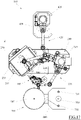
- the machine 100 first of all comprises a functional arrangement 105 provided with a reel 110 on which the covering tape 800 is wound.
- This reel 110 is rotatably associated with the functional arrangement 105, so as to be able to rotate on itself around a predetermined rotation axis A which generally coincides with the winding axis of the covering tape 800 on the reel 110 itself.
- a braking device (not illustrated), which is able to oppose a certain resistance to the rotation of the reel 110 around the respective rotation axis A, can be associated with the reel 110.
- the functional arrangement 105 may further comprise a cutting device 115, which is adapted to cut the covering tape 800 unwinding from the reel 110, so as to separate a segment thereof.
- the cutting device 115 can comprise a blade 120, for example a rotating blade, and actuator members 125 adapted to move said blade 120 with respect to the covering tape 800 unwinding from the reel 110.
- the blade 120 can be driven for moving in a sliding direction parallel to the covering tape 800 but transversal, typically orthogonal, with respect to an advancement direction with which said covering tape 800 unwinds from the reel 110.
- the sliding direction of the blade 120 can be parallel to the rotation axis A of the reel 110.
- the sliding of the blade 120 allows the covering tape 800 to be cut through along its entire width, subdividing it into two separate segments.
- the actuator members 125 of the blade 120 can comprise a cylinder/piston arrangement of the pneumatic type or any other device, for example electromechanical, adapted to impose a linear type movement on the blade 120.
- the functional arrangement 105 may also comprise a blocking device 130 which, with respect to the advancement direction of the covering tape 800, is positioned between the reel 110 and the cutting device 115.
- the blocking device 130 is preferably placed near, for example substantially close to the blade 120 and is adapted to stably block the covering tape 800 to allow/facilitate the cutting action by the blade 120.
- this blocking device 130 can comprise a pair of plates 135, which are flat and mutually opposite each other, between which the covering tape 800 unwinding from the reel 110 passes.
- These plates 135 can be associated with actuator members (not visible) adapted to engage them in a relative movement, for example in a direction orthogonal to the covering tape 800, between a distanced configuration and a neared configuration.
- This relative movement can be obtained for example by keeping one of the two plates 135 stationary and by moving the other towards/away from the first one.
- the covering tape 800 is stably blocked and clamped between the plates 135, which prevent it from advancing.
- the actuator members of the plates 135 can comprise a cylinder/piston arrangement of the pneumatic type or any other device suitable for the purpose, for example of the electromechanical type.
- the functional arrangement 105 may comprise an advancement device 145 which, with respect to the advancement direction of the covering tape 800, is preferably positioned between the reel 110 and the cutting device 115, for example upstream and/or close to the blocking device 130.
- This advancement device 145 can comprise a drive roller 150 adapted to receive the covering tape 800 in contact, and a motor 140 (see Fig. 3 ) adapted to put the drive roller 150 in rotation around its central axis B.
- the central axis B of the drive roller 150 is preferably parallel to the rotation axis A of the reel 110.
- the advancement device 145 can further comprise a contrast roller 155, which is adapted to rotate on itself (typically in an idle way) around its own central axis C, and is adapted to press the covering tape 800 against the drive roller 150.
- a contrast roller 155 which is adapted to rotate on itself (typically in an idle way) around its own central axis C, and is adapted to press the covering tape 800 against the drive roller 150.
- the central axis C of the contrast roller 155 is preferably parallel to the central axis B of the drive roller 150.
- the advancement device 145 can comprise actuator members 160 (see Fig. 3 ) adapted to engage the drive roller 150 and the contrast roller 155 in a relative movement, for example in a direction transverse to the respective central axes B and C, between a distanced configuration and a neared configuration.
- the covering tape 800 passes through them with a certain clearance, thus being free to slide independently of the drive roller 150.
- the covering belt 800 is stably blocked and clamped between these two rollers, so that the sliding thereof in the advancement direction is generated by the rotation of the drive roller 150.
- This relative movement between the distanced position and the neared position can be obtained by keeping the drive roller 150 stationary and by moving only the contrast roller 155 towards/away from the drive roller 150.
- the contrast roller 155 can be rotatably coupled to at least one connecting rod 165, which is in turn adapted to rotate around a rotation axis D parallel but distanced with respect to the central axis C of the contrast roller 155 and to central axis B of the drive roller 150.
- the actuator members 160 are therefore capable of moving the contrast roller 155 towards/away from the drive roller 150.
- actuator members of the plates 160 can comprise for example a cylinder/piston arrangement of the pneumatic type or any other device suitable for the purpose, for example of the electromechanical type.
- the functional arrangement 105 can comprise a pair of supporting rollers 170.
- These supporting rollers 170 can be adapted to rotate on themselves (generally in an idle way), each around a respective axis parallel to the rotation axis A of the reel 110.
- the supporting rollers 170 are neared between them but separated by a gap which is aligned with the advancement direction of the covering tape 800 through the cutting device 115.
- the gap between the supporting rollers 170 can be aligned with the gap formed between the plates 135 of the blocking device 130, when they are in a distanced configuration.
- the covering tape 800 is made to advance by the advancement device 145, after each cutting operation, the free end of the covering tape 800 passes in the gap between the supporting rollers 170, which guide it for sliding outwards, keeping it substantially stretched out.
- the functional arrangement 105 can further comprise a spatula 175, which can be installed downstream of the cutting device 115, with respect to the advancement direction of the covering tape 800.
- the spatula 175 can be positioned on the opposite side of the cutting device 115 with respect to the position occupied by the advancement device 145.
- the supporting rollers 170 (if any) can be positioned between the cutting device 115 and this spatula 175.
- the spatula 175 can be shaped as a flat sheet, for example rectangular in shape, having at least one extremal edge 180 that extends parallel to the rotation axis A of the reel 110.
- This spatula 175 can be positioned so as to ideally intersect the advancement direction with which the covering tape 800 passes through the cutting device 115.
- the spatula 175 can also be inclined with respect to said advancement direction, for example by an angle comprised between 0° and 90° (extremes excluded), preferably by an angle comprised between 20° and 70° (extremes included).
- the spatula 175 can be made of a flexible material, such as rubber.
- the functional arrangement 105 can then comprise one or more guide rollers, which are adapted to guide the covering tape unwinding from the reel 110 in a predetermined, more or less long and tortuous, path before reaching the advancement device 145 and from here the cutting device 115.
- These guide rollers may also have rotation axes parallel to the rotation axis A of the reel 110.
- the guide rollers comprise at least one motorised drive roller 185, to which a respective contrast roller 190 is associated, operating in a manner similar to those described with reference to the advancement device 145.
- the guide rollers can further comprise at least one tensioning roller 195, which is rotatably coupled (generally in an idle way) to at least one support connecting rod 200 which, being adapted to oscillate rotating around an axis that is parallel but distanced from the axis of the tensioning roller 195, is capable of varying its position in order to keep the covering tape 800 at a certain tension.
- the guide rollers can finally comprise one or more return rollers 205 positioned between the reel 110 and the drive roller 185 and/or between the drive roller 185 and the tensioning roller 195 and/or between the tensioning roller 195 and the advancement device 145, so as to make the path of the covering tape 800 more or less tortuous and long.
- the layout of the guide rollers illustrated in figure 5 corresponds to that currently used on the unwinders of machines designed to stabilise palletised loads with stretch film tapes, from which it follows that these unwinders can be retrofitted in order to be used in the present application, simply by adding the cutting device 115 and possibly the blocking device 130, the advancement device 145 and the spatula 175.
- the functional arrangement 105 substantially comprises a single rigid frame 210, on which both the reel 110 and the cutting device 115, as well as possibly each of the other devices and apparatuses described above, including for example the blocking device 130, the advancement device 145 and the spatula 175, are installed.
- the functional arrangement 105 can be manipulated as a single rigid body.
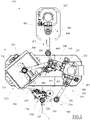
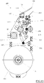
- the machine 100 can comprise a first movement apparatus 215 adapted to produce a relative motion of revolution of the functional arrangement 105 around the palletised load 900, with respect to a predetermined, preferably vertical, revolution axis Z (see fig. 1 ).
- Relative motion of revolution means that the functional arrangement 105 rotates around the palletised load 900 with respect to a reference system integral with the palletised load 900, regardless of whether the actual movement is imparted to the functional arrangement 105 or to the palletised load 900.
- the first movement apparatus 215 is actually adapted to put the palletised load 900 in rotation on itself.
- the first movement apparatus 215 can comprise a platform 220, which makes a rest surface 225, preferably horizontal, available for the palletised load 900.
- the rest surface 225 can be defined by a roller conveyor which, when installed on the platform 220, facilitates the positioning and subsequent distancing of the palletised load 900.
- the first movement apparatus 215 further comprises actuator members (not illustrated) adapted to put the platform 220 in rotation around a rotation axis orthogonal to the rest surface 225 and coincident with the axis, for example substantially vertical, of revolution Z.
- the rotation axis of the platform 220 can pass internally to the rest surface 225, so that the palletised load 900 can substantially pivot on itself.
- the machine 100 can comprise an upper pad 235, which is adapted to stay in contact with the top of the palletised load 900.
- This upper pad 235 can be substantially shaped as a flat plate, for example substantially rectangular/square in shape, and oriented horizontally.
- the upper pad 235 can be associated with a lifting apparatus 240 adapted to move it in the vertical direction, so as to bring it closer to and away from the rest surface 225, for example to free the palletised load 900 or to adjust the position thereof according to the height of the latter.
- This lifting apparatus 240 can comprise for example a supporting column 245 and a carriage 250 slidingly associated with the supporting column 245, so as to be able to slide on it in a vertical direction, driven by suitable motors.
- the supporting column 245 can be provided with linear sliding guides 255, oriented vertically, on which corresponding coupling runners fixed to the carriage 250 slide.
- the lifting apparatus 240 can further comprise a cantilevered, preferably horizontal, arm 260 which connects the carriage 250 to the upper pad 235.
- one end of the cantilevered arm 260 can be articulated to the carriage 250 according to a vertical articulation axis, so that the cantilevered arm 260 can rotate like a flag.
- This rotation of the cantilevered arm 260 can be driven by an electric motor 265.
- the upper pad 235 can also be adapted to rotate on itself around an axis of vertical rotation, which is coincident (or can be brought so as to be coincident) with the revolution axis Z.
- the upper pad 235 can be hinged, according to said rotation axis, to a second end of the cantilevered arm 260, and can be drive for rotation by a motor 270 or by any other actuator member.
- the rotation of the upper pad 235 occurs substantially simultaneously and substantially at the same speed as the rotation of the platform 220, so that the palletised load 900 is not subjected to significant torsional stresses.
- a first movement apparatus 215 adapted to rotate the palletised load 900 it is not excluded that, in other embodiments, the palletised load 900 may remain stationary, for example resting on a rest surface 225 made available by a floor or any other fixed base, and that the first movement apparatus 215 is configured to actively move the functional arrangement 105 with a revolution movement around the palletised load 900.
- the machine 100 could in any case comprise an upper pad 235 adapted to remain in contact and integral with the top of the palletised load 900 (in this case also stationary).
- the machine 100 further comprises a second movement apparatus 275, which is adapted to produce a relative motion of translation of the functional arrangement 105 with respect to the palletised load 900, along a direction parallel to the revolution axis Z, or preferably in the vertical direction.
- Relative motion of translation means that the functional arrangement 105 and the palletised load 900 are mutually movable in a direction parallel to the revolution axis Z, regardless of whether the actual movement is of one or the other.
- the second movement apparatus 275 is adapted to actively move the functional arrangement 105 in the vertical direction, while the palletised load 900 remains stable on the rest surface 225.
- the second movement apparatus 275 may be configured to move the palletised load 900 vertically, for example by lifting and/or lowering the corresponding platform 220.
- the second movement apparatus 275 is preferably configured to also allow a displacement of the functional arrangement in a plane orthogonal to the revolution axis Z, that is in a preferably horizontal plane, as well as to allow a variation in the orientation of the functional arrangement 105, and consequently of the rotation axis A of the reel 110, through rotation around a further oscillation axis Y perpendicular to the revolution axis Z, that is preferably horizontal.
- the second movement apparatus 275 can first of all comprise a supporting column and a carriage 280 slidingly associated with said supporting column, so as to be able to slide vertically thereon, driven by suitable motors.
- the supporting column of the second movement apparatus 275 can coincide with the supporting column 245 of the lifting apparatus 240 of the upper pad 235.
- the supporting column 245 can be provided with linear sliding guides 285, oriented vertically, on which corresponding coupling runners fixed to the carriage 280 slide.
- the second movement apparatus 275 can further comprise a cantilevered arm 290, preferably horizontal, which connects the carriage 280 to the functional arrangement 105, that is to the rigid frame 210.
- the cantilevered arm 290 can be an articulated arm with parallel, for example all vertical, axes to allow a more efficient positioning of the functional arrangement 105.
- the cantilevered arm 290 can comprise two stretches in series, of which a first stretch 295 articulated to the carriage 280 and a second stretch 300 articulated to the free end of the first stretch 295.
- the rotation of the first stretch 295 with respect to the carriage 280 can be driven by an electric motor 305, while the rotation of the second stretch 300 with respect to the first stretch 295 can be driven by another electric motor 310.
- the carriage 280 and the cantilevered arm 290 define a so-called SCARA robot.
- the rigid frame 210 of the functional arrangement 105 can be connected to the cantilevered arm 290, i.e. to the free end of the second stretch 300, by interposition of an intermediate body 315 (see Fig. 4 ).
- This intermediate body 315 can be articulated to the cantilevered arm 290 by means of an articulated joint which allows it to rotate around an articulation axis parallel to that defined between the cantilevered arm 290 and the carriage 250, i.e. preferably vertical.
- the rotation of the intermediate body 315 with respect to this articulation axis can be driven by an electric motor 320.
- the intermediate body 315 can then be articulated to the rigid frame 210 of the functional arrangement 105 by means of a further articulated joint which defines the already mentioned oscillation axis Y.
- the rotation of the functional arrangement 105 with respect to this oscillation axis Y can be driven by a further electric motor 325.
- the machine 100 further comprises a gripping device 350, which is adapted to seize a first end of the covering tape 800 unwinding from the reel 110 and to make it integral with the palletised load 900.
- This gripping device 350 can be positioned at the base or, more preferably, at the top of the palletised load 900 and is adapted to remain integral with the latter during the relative revolution and translation movements of the functional arrangement 105.
- the gripping device 350 can be installed on the platform 220 or, more preferably, on the edge of the upper pad 235.
- this gripping device 350 can comprise a gripper member 355 provided with at least two jaws that are reciprocally movable towards and away from each other, so as to be able to selectively clamp or release an edge of the covering tape 800 which is positioned between them.
- This movement of the jaws of the gripper member 355 can be driven by means of a cylinder-piston arrangement 345 of the pneumatic type or by any other actuation system, for example electromechanical.
- the jaws of the gripper member 355 can protrude at least slightly from the upper pad 235 towards the rest surface 225, so as to be at least partially flanked to the side wall of the palletised load 900.
- the gripping device 350 can further comprise actuator members 360 adapted to move the gripper member 355 along a predetermined sliding direction, towards and away from the revolution axis Z, and therefore with respect to the side wall of the palletised load 900.
- the sliding direction of the gripper member 355 can be orthogonal to the revolution axis Z, for example horizontal.
- actuator members 365 can further be provided to move the gripper member 355 also in a direction parallel to the revolution axis Z.
- the gripper member 355 can be positioned at a slot obtained in the upper pad 235, installed on board a carriage 370 which is slidingly coupled to linear guides 375, oriented parallel to the sliding direction, which can be fixed above the upper pad 235.
- the actuator members 360 can comprise a cylinder-piston arrangement of the pneumatic type or any other type of actuator, for example electromechanical, adapted to make the carriage 370 slide on the linear guides 375.
- the actuator members 365 may comprise another cylinder-piston arrangement of the pneumatic type or any other type of actuator, for example electromechanical, adapted to make the gripper member slide on the linear guides 380.
- the machine 100 further comprises a fixing device 400, which is adapted to fix the windings of covering tape 800 around the palletised load 900.
- this fixing device 400 comprises one or more guns for dispensing an adhesive adapted to be applied on the windings of the covering tape 800.
- these dispensing guns can comprise one or more dispensing guns 405 of a hot glue and, optionally, one or more dispensing guns 410 of a cold glue.
- the fixing device 400 may comprise only hot glue dispensing guns 405 or only cold glue dispensing guns 410.
- the fixing device 400 can be installed on a rigid frame 415, independent and separate from the rigid frame 210 of the functional arrangement 105.
- the rigid frame 415 can be associated with a third movement apparatus 420, which is adapted to move the fixing device 400 at least along a direction parallel to the revolution axis Z, for example vertical, and, more preferably, also in multiple positions in the plane orthogonal to said revolution axis Z, so as to be able to suitably place it with respect to the palletised load 900.
- a third movement apparatus 420 which is adapted to move the fixing device 400 at least along a direction parallel to the revolution axis Z, for example vertical, and, more preferably, also in multiple positions in the plane orthogonal to said revolution axis Z, so as to be able to suitably place it with respect to the palletised load 900.
- the third movement apparatus 420 can be configured as a SCARA robot, which comprises a supporting column 425, a carriage 430 slidingly associated with the supporting column 425, so as to move in a vertical direction (driven by suitable motors), and a cantilevered arm 435 adapted to connect the carriage 430 to the frame 415 of the fixing device 400.
- SCARA robot which comprises a supporting column 425, a carriage 430 slidingly associated with the supporting column 425, so as to move in a vertical direction (driven by suitable motors), and a cantilevered arm 435 adapted to connect the carriage 430 to the frame 415 of the fixing device 400.
- the cantilevered arm 435 can be an articulated arm with parallel, for example all vertical, axes, which comprises a first stretch 440 articulated to the carriage 430 and a second stretch 445 articulated to the first stretch 440 and to the rigid frame 415 of the fixing device 400.
- Each of these joints can be driven by a respective independent electric motor.
- the palletised load 900 is loaded onto the rest surface 225 and the upper pad 235 is brought into contact with the top thereof, possibly causing it to exert a certain downward pressure.
- the functional arrangement 105 can be oriented, by means of the second movement apparatus 275, in such a way that the rotation axis A of the reel 110 and thus the orientation of the covering tape 800 are substantially parallel to the revolution axis Z, i.e. substantially vertical.
- the functional arrangement 105 can be brought close to the palletised load 900 and at the gripping device 350, so that a first (free) end of the covering tape 800 associated with the reel 110, i.e. the one protruding downstream of the cutting device 115, can be vertically aligned with the gripper member 355.
- the gripper member 355 can be lowered, so that said first end of the covering tape 800 slips between the jaws thereof, which are subsequently clamped together in order to seize it and hold it firmly.
- the gripper member 355 can be moved towards the revolution axis Z, dragging therewith the covering tape 800 (which therefore begins to unwind from the reel 110), until it is positioned in the immediate vicinity of the side wall of the palletised load 900.
- the platform 220 and the upper pad 235 can be put in rotation around the revolution axis Z, by correspondingly activating the rotation of the palletised load 900 as well.
- the reel 110 which is on board the functional arrangement 105 begins to perform a relative revolution movement around the palletised load 900.
- the covering tape 800 is automatically dragged so as to unwind from the reel 110 and to wind around the palletised load 900.
- the advancement device 145 of the functional arrangement 105 is inactive, for example with the drive roller 150 stationary and the contrast roller 155 in a distanced configuration.
- the first windings of covering tape 800 can be perfectly horizontal and mutually superimposed at the top band of the palletised load 900.
- the gripping device 350 can optionally release the first end of the covering tape 800 which remains integral with the palletised load 900 thanks to the windings.
- the second movement apparatus 275 can begin to displace the functional arrangement 105 in a vertical downward direction.
- the covering tape 800 is wound around the palletised load 900 with a spiral course, until it completely covers the side wall (see Fig. 10 ).
- the second movement apparatus 275 orients the functional arrangement 105, by making it rotate around the oscillation axis Y (or allowing it to rotate around the oscillation axis Y), in such a way that the rotation axis A of the reel 110 always remains substantially orthogonal to the direction of the helix.
- the dispensing guns of the fixing device 400 can dispense (e.g. spray) a certain amount of adhesive onto the winding of the covering tape 800 that has been previously made, so that said adhesive remains interposed between the previous winding and the one being made, joining them together and making the wrapping more stable.
- the adhesive used in this step can be the cold glue dispensed by the dispensing guns 410.
- the translational movement of the functional arrangement 105 is stopped and it can be made to rotate around the oscillation axis Y, so as to bring back the rotation axis of the reel 110 vertically.
- the platform 220 and the upper pad 235 can be stopped.
- the dispensing guns of the fixing device 400 can therefore be commanded for dispensing (e.g. spraying) a certain amount of adhesive onto the portion of the envelope facing the last stretch of the covering tape 800 coming from the reel 110.
- the adhesive used in this step can be the hot glue dispensed by the dispensing guns 405, as it is characterized by shorter setting times than the cold glue.
- the functional arrangement 105 can then be approached to the palletised load 900 (see fig. 12 ), so as to begin to bring the last stretch of the covering tape 800 coming from the reel 110 into contact with the palletised load 900, above the previously dispensed adhesive.
- the cutting device 115 comes into operation which separates the segment of covering tape 800 wound around the palletised load 900 from the one that remains connected to the reel 110.
- the segment of covering tape 800 wound around the palletised load 900 will have a second free end, which can be stretched and pressed against the adhesive previously dispensed by means of the extremal edge 180 of the spatula 175 which, by means of the second movement apparatus 275, is brought into contact and suitably made to slide against the previously wrapped palletised load 900.
- the segment of covering tape 800 which remains associated with the reel 110 will now have a new free end positioned at the cutting device 115, for example blocked by the blocking device 130.
- the advancement device 145 can now be put into operation (not illustrated in figure 12 ).
- the contrast roller 155 can be brought into contact with the drive roller 150 and the latter can be driven for rotation, so as to unwind at least a part of the covering tape 800 from the reel 110, thus making it advance until the free end will be sufficiently protruding to be seized again by the gripper member 355 of the gripping device 350.
- the operation of the machine 100 can be entirely commanded and controlled by at least one electronic unit (not illustrated), which is suitably programmed and connected with the various devices and apparatuses of the machine 100.
- a first of these aspects is that the third movement apparatus 420 of the fixing device 400 shares the same supporting column 245 with the second movement apparatus 275 of the functional arrangement 105 and with the lifting apparatus 240 of the upper pad 235.
- the carriage 430 of the third movement apparatus 420 is slidingly associated with the same supporting column 245 to which the carriages 250 and 280 respectively of the lifting apparatus 240 and of the second movement apparatus 275 are also slidingly associated.
- Another aspect of diversity consists in the fact that the functional arrangement 105 is simplified.
- the functional arrangement 105 comprises a single rigid frame 210 on which the reel 110, the cutting device 115 and, possibly, the blocking device 130, the advancement device 145, the supporting rollers 170 and the spatula 175 are installed.
- the reel 110 is also motorised, that is, it is connected to a drive motor 450 (see Fig. 13 ) adapted to put it in rotation around its own rotation axis A.
- the drive motor 450 can be part of the functional arrangement 105, for example installed on the rigid frame 210, and can be connected to the reel 110 via a belt or any other transmission system.
- the function of the drive motor 450 is preferably to rotate the reel 110 in the winding direction, so as to rewind the covering tape 800 thereon.
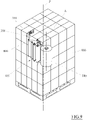
- the machine 100 can comprise a service apparatus 500 adapted to house at least two mutually interchangeable functional arrangements 105, for example identical to each other, one of which can be connected in use to the second movement apparatus 275 while the other can be left in the service apparatus 500.
- a service apparatus 500 adapted to house at least two mutually interchangeable functional arrangements 105, for example identical to each other, one of which can be connected in use to the second movement apparatus 275 while the other can be left in the service apparatus 500.
- this first functional arrangement 105 can be stowed in the service apparatus 500 and immediately replaced with the second functional arrangement 105.
- the functional arrangement 105 can be connected to the second movement apparatus 275 by means of an automatic hooking and unhooking system.
- the respective reel 110 can be reloaded with the covering tape 800.
- This covering tape 800 can for example be supplied by the manufacturer in large-sized reels 505, one of which can be rotatably installed at the service apparatus 500.
- the free edge of the covering tape 800 wound on this reel 505 can be made to pass backwards through the cutting device 130 and any other accessory devices of the first functional arrangement 105, to be finally connected to the respective reel 110.
- the reel 110 can then be put in rotation by the motor 450 until it is reloaded with a desired number of windings of the covering tape 800, after which the cutting device 130 can be put into action to separate the segment of the winding tape 800. wound on reel 110 from that eventually still wound on the reel 505.
- the second movement apparatus 275 can stow it back in the service apparatus 500, to be in turn reloaded as explained above, and pick up again the first functional arrangement 105 which in the meantime has already been reloaded.
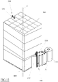
- the machine 100 can be, for example, substantially identical to that illustrated in Figures 1 and 2 , with the difference of comprising two or more interchangeable reels 110, for example identical to each other, a first of which can be connected in use in the functional arrangement 105 while the others can be left in a service apparatus 700.
- the functional arrangement 105 can release this reel 110 in the service apparatus 700 and pick up therefrom one of the other reels 110.
- the first reel 110 When the first reel 110 is in the service apparatus 700, the same can be reloaded with the covering tape 800.
- the functional arrangement 105 can comprise an automatic system for hooking and unhooking the reels 110.
- the service apparatus 700 can comprise a plurality of spindles 705, each of which is adapted to receive a reel 110 and is put in rotation by a respective motor 710.
- Each reel 110 may comprise a central shaft 715, for example made of steel, which engages on the spindle 705 when the reel 110 is released in the service apparatus 700.
- the covering tape 800 is unwound from the reel 505 made available by the supplier and connected directly to the central shaft 715 which, by rotating together with the spindle 705, winds the covering tape 800 around itself.
- the reel 110 is then disengaged from the spindle 705 and finally hooked to the functional arrangement 105 together with its own central shaft 715.
- the reel 110 could comprise a cylindrical core, for example made of cardboard.
- each spindle 705 could comprise a shaft, for example an expansion shaft, on which the cylindrical core of the reel 110 is fitted.
- the covering tape 800 is then fixed to the cylindrical core which, by rotating together with the spindle 705, forms the reel 110.
- the reel 110 is then removed from the shaft of the spindle 705 and finally hooked to the functional arrangement 105 together with the respective cylindrical core.
- cylindrical cores After usage on board the functional arrangement 105, the cylindrical cores can be reused or replaced with new ones.
- the service apparatus 700 could also be used independently of the machine 100, for example to prepare a certain number of reels 110 which are then stored and used from time to time on the machine 100 when necessary, or for preparing reels of covering tape 800 useful for other purposes.
- the service apparatus 700 comprises a cutting device for separating the segment of winding tape 800 wound on the reel 110 from that eventually still wound on the supplier's reel 505.
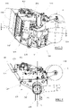
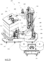
- the embodiment illustrated in Figures 18 to 20 differs from the previous ones, mainly due to the fact that the second movement apparatus 275 comprises a serial manipulator 550, having at least five or six axes, to whose terminal the functional arrangement 105 is connected.
- serial manipulator 550 can be of the industrial type and can therefore be suitable for bearing higher weights than those a SCARA robot such as those illustrated in the previous embodiments can carry.
- the reel 110 installed in the functional arrangement 105 may be much larger, for example it may be one of the reels that are directly supplied by the manufacturer of the covering tape 800 (previously indicated with 505).
- the reel 110 can be associated with a more performing braking device 555.
- the functional arrangement 105 is nevertheless similar to that described in the second embodiment.
- it comprises a single rigid frame 210 on which the reel 110, the cutting device 115 and, possibly, the blocking device 130, the advancement device 145, the supporting rollers 170, the spatula 175, the return rollers 205 and the tensioning roller 195 are installed.
- the functional arrangement 105 can in any case comprise an automatic system for hooking and unhooking the reel 110, to allow the rapid replacement of an exhausted reel 110 with another new reel 110, which can be previously placed on hold at a predetermined storage area.
- the fixing device 400 for example the adhesive dispensing guns 405 and/or 410, can be part of the functional arrangement 105, for example it can be installed on the rigid frame 210.
- the upper pad 235 is instead still carried by the respective lifting apparatus 240 which, in this case, is completely separated from the second movement apparatus 275.
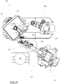
- the embodiment illustrated in figures 21 to 23 differs from the previous one in that the functional arrangement 105 comprises two separate rigid frames, of which a first rigid frame 210 and a second rigid frame 600.
- the cutting device 115 as well as, optionally, the blocking device 130, the advancement device 145, the supporting rollers 170, the spatula 175, the return rollers 205 and the tensioning roller 195 are installed on the first rigid frame 210.
- the fixing device 400 can also be installed on the first rigid frame 210.
- the reel 110 is installed with the relative braking device (if any), preferably through an automatic hooking and unhooking system, to allow it to be quickly replaced.
- the reel 110 can be large sized, for example it can be one of the reels that are directly supplied by the manufacturer of the covering tape 800.
- the first frame 210 and the second frame 600 can be connected by means of a connection arm 605.
- connection arm 605 can be an articulated arm entirely similar to the cantilevered arm 290 of the first embodiment.
- connection arm 605 can comprise two stretches in series, of which a first stretch 610 articulated to the second rigid frame 600 and a second stretch 615 articulated to the free end of the first stretch 610, with mutually parallel articulation axes.
- the rotation of the first stretch 610 with respect to the second rigid frame 600 can be driven by an electric motor 620, while the rotation of the second stretch 615 with respect to the first stretch 610 can be driven by another independent electric motor 625.
- the first rigid frame 210 can be connected to the connection arm 605, i.e. to the free end of the second stretch 615, by interposition of a joint adapted to define a single axis of mutual articulation, parallel to the articulation axis between the first stretch 610 and the second stretch 615.
- the second movement apparatus 275 can further comprise a supporting column, which can coincide with the supporting column 245 of the lifting apparatus 240 of the upper pad 235, and a carriage 280 connected to the functional arrangement 105, in this case to the second rigid frame 600, which is slidingly associated with said supporting column, so as to be able to slide vertically thereon, driven by suitable motors.
- the second movement apparatus 275 can further comprise an articulated joint 630 (see fig. 22 ) adapted to connect the carriage 280 to the second rigid frame 600 of functional arrangement 105, which is adapted to define the oscillation axis Y which, also in this case, is perpendicular to the revolution axis Z, i.e. preferably horizontal.
- an articulated joint 630 (see fig. 22 ) adapted to connect the carriage 280 to the second rigid frame 600 of functional arrangement 105, which is adapted to define the oscillation axis Y which, also in this case, is perpendicular to the revolution axis Z, i.e. preferably horizontal.
- the rotation of the second rigid frame 600 with respect to the carriage 280 around said oscillation axis Y can be driven by a motor 635.
Landscapes
- Engineering & Computer Science (AREA)
- Mechanical Engineering (AREA)
- Basic Packing Technique (AREA)
- Pallets (AREA)
Applications Claiming Priority (1)
| Application Number | Priority Date | Filing Date | Title |
|---|---|---|---|
| IT202000029396 | 2020-12-02 |
Publications (1)
| Publication Number | Publication Date |
|---|---|
| EP4008638A1 true EP4008638A1 (de) | 2022-06-08 |
Family
ID=74557207
Family Applications (1)
| Application Number | Title | Priority Date | Filing Date |
|---|---|---|---|
| EP21210245.3A Pending EP4008638A1 (de) | 2020-12-02 | 2021-11-24 | Maschine und verfahren zum stabilisieren von palettierten lasten |
Country Status (3)
| Country | Link |
|---|---|
| US (1) | US11827393B2 (de) |
| EP (1) | EP4008638A1 (de) |
| MX (1) | MX2021014798A (de) |
Cited By (1)
| Publication number | Priority date | Publication date | Assignee | Title |
|---|---|---|---|---|
| AT525393A1 (de) * | 2021-08-25 | 2023-03-15 | Mondi Ag | Vorrichtung, Anordnung und Verfahren zum Verpacken von Ladegut mit einer Papierbahn |
Families Citing this family (4)
| Publication number | Priority date | Publication date | Assignee | Title |
|---|---|---|---|---|
| US20220204198A1 (en) * | 2012-06-18 | 2022-06-30 | TAB Industries, LLC | Exhaust Blower for Orbital Pallet Wrappers |
| WO2021178189A1 (en) * | 2020-03-03 | 2021-09-10 | Lantech.Com, Llc | Load wrapping apparatus and method utilizing packaging material with recycled content |
| US20220169468A1 (en) * | 2020-11-30 | 2022-06-02 | Neil G. Cousins | Stretch wrap film carriage |
| IT202100011720A1 (it) * | 2021-05-07 | 2022-11-07 | A C M I Spa | Macchina per la stabilizzazione di carichi palettizzati con sistema di cambio bobina |
Citations (6)
| Publication number | Priority date | Publication date | Assignee | Title |
|---|---|---|---|---|
| GB2059906A (en) * | 1979-09-12 | 1981-04-29 | Lancaster W G | A process and apparatus for wrapping loads in stretch films |
| DE3150627A1 (de) * | 1981-03-31 | 1982-10-07 | Infra Pak (Dallas), Inc., Dallas, Tex. | Vorspanneinrichtung fuer folienbahnen |
| DE3906873A1 (de) * | 1988-03-14 | 1989-09-28 | Fmc Corp | Vorrichtung und verfahren zum stapeln und umwickeln von gegenstaenden |
| US20100025517A1 (en) * | 2006-11-17 | 2010-02-04 | Aetna Group, S.P.A. | Apparatus for changing film reels |
| ITMO20090032A1 (it) * | 2009-02-10 | 2010-08-11 | Sacmi Forni Spa | Apparato per la preparazione di un carico pallettizzato |
| IT201800002676A1 (it) * | 2018-02-14 | 2019-08-14 | Aetna Group Spa | Macchina avvolgitrice |
Family Cites Families (6)
| Publication number | Priority date | Publication date | Assignee | Title |
|---|---|---|---|---|
| FR2664565B1 (fr) * | 1990-07-16 | 1994-05-13 | Newtec International | Procede et machine d'emballage de la face laterale et d'une face d'extremite d'une charge. |
| FR2681311B1 (fr) * | 1991-09-17 | 1993-12-10 | Philippe Fandard | Procede pour conditionner une charge palettisable et installation pour la mise en óoeuvre de ce procede. |
| CA2276122C (en) * | 1998-11-06 | 2008-11-18 | Wulftec International Inc. | Wrapping machine for wrapping an article from a roll of film, and a method thereof |
| ITVR20110049A1 (it) * | 2011-03-09 | 2012-09-10 | Bema Srl | Impianto per la fasciatura di carichi |
| EP2744711B9 (de) * | 2011-08-16 | 2016-09-28 | Aetna Group S.P.A. | System zum bewegen von bedieneinheiten für eine verpackungsmaschine und verpackungsmaschine |
| US9394069B2 (en) * | 2011-09-30 | 2016-07-19 | Brenton Llc | Corner protector placement system and method and related pallet wrapping system and method |
-
2021
- 2021-11-24 EP EP21210245.3A patent/EP4008638A1/de active Pending
- 2021-11-30 US US17/538,088 patent/US11827393B2/en active Active
- 2021-12-01 MX MX2021014798A patent/MX2021014798A/es unknown
Patent Citations (6)
| Publication number | Priority date | Publication date | Assignee | Title |
|---|---|---|---|---|
| GB2059906A (en) * | 1979-09-12 | 1981-04-29 | Lancaster W G | A process and apparatus for wrapping loads in stretch films |
| DE3150627A1 (de) * | 1981-03-31 | 1982-10-07 | Infra Pak (Dallas), Inc., Dallas, Tex. | Vorspanneinrichtung fuer folienbahnen |
| DE3906873A1 (de) * | 1988-03-14 | 1989-09-28 | Fmc Corp | Vorrichtung und verfahren zum stapeln und umwickeln von gegenstaenden |
| US20100025517A1 (en) * | 2006-11-17 | 2010-02-04 | Aetna Group, S.P.A. | Apparatus for changing film reels |
| ITMO20090032A1 (it) * | 2009-02-10 | 2010-08-11 | Sacmi Forni Spa | Apparato per la preparazione di un carico pallettizzato |
| IT201800002676A1 (it) * | 2018-02-14 | 2019-08-14 | Aetna Group Spa | Macchina avvolgitrice |
Cited By (2)
| Publication number | Priority date | Publication date | Assignee | Title |
|---|---|---|---|---|
| AT525393A1 (de) * | 2021-08-25 | 2023-03-15 | Mondi Ag | Vorrichtung, Anordnung und Verfahren zum Verpacken von Ladegut mit einer Papierbahn |
| AT525393B1 (de) * | 2021-08-25 | 2023-08-15 | Mondi Ag | Vorrichtung, Anordnung und Verfahren zum Verpacken von Ladegut mit einer Papierbahn |
Also Published As
| Publication number | Publication date |
|---|---|
| US20220169407A1 (en) | 2022-06-02 |
| MX2021014798A (es) | 2022-07-12 |
| US11827393B2 (en) | 2023-11-28 |
Similar Documents
| Publication | Publication Date | Title |
|---|---|---|
| US11827393B2 (en) | Machine and method for stabilising palletised loads | |
| US4300326A (en) | Stretch wrapping apparatus with mechanical closure | |
| US7837140B2 (en) | Automatic film changer for a film wrapping machine | |
| US5452566A (en) | Device for handling and maintenance of the free end of a film in a wrapping machine | |
| EP0867368B1 (de) | Verfahren und Vorrichtung zum Umhüllen einer Ladung mit Dehnfolie | |
| US11858669B2 (en) | Device for applying cover sheets to palletised loads | |
| KR102098091B1 (ko) | 전선 자동 바인딩 포장장치 | |
| US11760514B2 (en) | Machine for stabilizing palletised loads with tensioning fins | |
| JPH01308708A (ja) | ストレッチラッピングを行うロボットパレタイザ | |
| TWI731533B (zh) | 卷盤自動更換系統 | |
| EP1438232B1 (de) | Vorrichtung und verfahren zur rollenverpackung komprimierbarer materialien | |
| EP4086210A1 (de) | Maschine zum abwickeln und aufwickeln eines zur stabilisierung palettierter lasten bestimmten abdeckbandes | |
| CN106560403B (zh) | 薄膜包装机薄膜供料 | |
| WO2004058571A1 (en) | Device and method for winding a flexible cable | |
| EP1074473B1 (de) | Verfahren und Maschine zum Verpacken von ringförmigen Strängen eines flexiblen länglichen Elements | |
| CN111727154B (zh) | 缠绕机 | |
| US11987406B2 (en) | Machine for stabilising palletised loads with reel change system | |
| US6892448B2 (en) | Automated roll packing apparatus | |
| WO2019159077A1 (en) | Wrapping machine | |
| CN114104800A (zh) | 一种带材收卷机器人 | |
| CN210823020U (zh) | 一种卧式薄膜手套装袋机 | |
| US20050056719A1 (en) | Splicing vehicle | |
| JPH01279011A (ja) | ストレッチ包装するパレタイザ装置 | |
| JP3290544B2 (ja) | 缶蓋包装体のパレタイジング装置 | |
| JP4668011B2 (ja) | 包装方法及び包装機 |
Legal Events
| Date | Code | Title | Description |
|---|---|---|---|
| PUAI | Public reference made under article 153(3) epc to a published international application that has entered the european phase |
Free format text: ORIGINAL CODE: 0009012 |
|
| STAA | Information on the status of an ep patent application or granted ep patent |
Free format text: STATUS: THE APPLICATION HAS BEEN PUBLISHED |
|
| AK | Designated contracting states |
Kind code of ref document: A1 Designated state(s): AL AT BE BG CH CY CZ DE DK EE ES FI FR GB GR HR HU IE IS IT LI LT LU LV MC MK MT NL NO PL PT RO RS SE SI SK SM TR |
|
| STAA | Information on the status of an ep patent application or granted ep patent |
Free format text: STATUS: REQUEST FOR EXAMINATION WAS MADE |
|
| 17P | Request for examination filed |
Effective date: 20221118 |
|
| RBV | Designated contracting states (corrected) |
Designated state(s): AL AT BE BG CH CY CZ DE DK EE ES FI FR GB GR HR HU IE IS IT LI LT LU LV MC MK MT NL NO PL PT RO RS SE SI SK SM TR |
|
| STAA | Information on the status of an ep patent application or granted ep patent |
Free format text: STATUS: EXAMINATION IS IN PROGRESS |
|
| 17Q | First examination report despatched |
Effective date: 20240411 |