EP4008433B1 - Verteilungssystem für diagnostisches labor - Google Patents
Verteilungssystem für diagnostisches labor Download PDFInfo
- Publication number
- EP4008433B1 EP4008433B1 EP20383055.9A EP20383055A EP4008433B1 EP 4008433 B1 EP4008433 B1 EP 4008433B1 EP 20383055 A EP20383055 A EP 20383055A EP 4008433 B1 EP4008433 B1 EP 4008433B1
- Authority
- EP
- European Patent Office
- Prior art keywords
- distribution system
- control device
- generating devices
- microbiological
- transport plane
- Prior art date
- Legal status (The legal status is an assumption and is not a legal conclusion. Google has not performed a legal analysis and makes no representation as to the accuracy of the status listed.)
- Active
Links
- 230000002906 microbiologic effect Effects 0.000 claims description 46
- 239000000969 carrier Substances 0.000 claims description 25
- 238000000034 method Methods 0.000 claims description 16
- 238000010438 heat treatment Methods 0.000 claims description 15
- 230000032258 transport Effects 0.000 description 34
- 241000531116 Blitum bonus-henricus Species 0.000 description 3
- 235000008645 Chenopodium bonus henricus Nutrition 0.000 description 3
- 210000001124 body fluid Anatomy 0.000 description 3
- 239000010839 body fluid Substances 0.000 description 3
- 238000011109 contamination Methods 0.000 description 3
- 238000005259 measurement Methods 0.000 description 3
- 239000000443 aerosol Substances 0.000 description 2
- 238000004891 communication Methods 0.000 description 2
- 238000012864 cross contamination Methods 0.000 description 2
- 238000001514 detection method Methods 0.000 description 2
- 239000000463 material Substances 0.000 description 2
- 235000015097 nutrients Nutrition 0.000 description 2
- 239000000523 sample Substances 0.000 description 2
- 239000003153 chemical reaction reagent Substances 0.000 description 1
- 238000009833 condensation Methods 0.000 description 1
- 230000005494 condensation Effects 0.000 description 1
- 230000001419 dependent effect Effects 0.000 description 1
- 239000006101 laboratory sample Substances 0.000 description 1
- 239000007788 liquid Substances 0.000 description 1
- 238000011169 microbiological contamination Methods 0.000 description 1
- 239000002245 particle Substances 0.000 description 1
- 230000037361 pathway Effects 0.000 description 1
- 238000003908 quality control method Methods 0.000 description 1
- 239000000126 substance Substances 0.000 description 1
- 239000002699 waste material Substances 0.000 description 1
Images
Classifications
-
- G—PHYSICS
- G01—MEASURING; TESTING
- G01N—INVESTIGATING OR ANALYSING MATERIALS BY DETERMINING THEIR CHEMICAL OR PHYSICAL PROPERTIES
- G01N35/00—Automatic analysis not limited to methods or materials provided for in any single one of groups G01N1/00 - G01N33/00; Handling materials therefor
- G01N35/02—Automatic analysis not limited to methods or materials provided for in any single one of groups G01N1/00 - G01N33/00; Handling materials therefor using a plurality of sample containers moved by a conveyor system past one or more treatment or analysis stations
- G01N35/04—Details of the conveyor system
-
- B—PERFORMING OPERATIONS; TRANSPORTING
- B01—PHYSICAL OR CHEMICAL PROCESSES OR APPARATUS IN GENERAL
- B01L—CHEMICAL OR PHYSICAL LABORATORY APPARATUS FOR GENERAL USE
- B01L1/00—Enclosures; Chambers
- B01L1/02—Air-pressure chambers; Air-locks therefor
- B01L1/025—Environmental chambers
-
- G—PHYSICS
- G01—MEASURING; TESTING
- G01N—INVESTIGATING OR ANALYSING MATERIALS BY DETERMINING THEIR CHEMICAL OR PHYSICAL PROPERTIES
- G01N35/00—Automatic analysis not limited to methods or materials provided for in any single one of groups G01N1/00 - G01N33/00; Handling materials therefor
- G01N35/10—Devices for transferring samples or any liquids to, in, or from, the analysis apparatus, e.g. suction devices, injection devices
- G01N35/1065—Multiple transfer devices
- G01N35/1067—Multiple transfer devices for transfer to or from containers having different spacing
-
- G—PHYSICS
- G01—MEASURING; TESTING
- G01N—INVESTIGATING OR ANALYSING MATERIALS BY DETERMINING THEIR CHEMICAL OR PHYSICAL PROPERTIES
- G01N35/00—Automatic analysis not limited to methods or materials provided for in any single one of groups G01N1/00 - G01N33/00; Handling materials therefor
-
- G—PHYSICS
- G01—MEASURING; TESTING
- G01N—INVESTIGATING OR ANALYSING MATERIALS BY DETERMINING THEIR CHEMICAL OR PHYSICAL PROPERTIES
- G01N35/00—Automatic analysis not limited to methods or materials provided for in any single one of groups G01N1/00 - G01N33/00; Handling materials therefor
- G01N35/02—Automatic analysis not limited to methods or materials provided for in any single one of groups G01N1/00 - G01N33/00; Handling materials therefor using a plurality of sample containers moved by a conveyor system past one or more treatment or analysis stations
-
- G—PHYSICS
- G01—MEASURING; TESTING
- G01N—INVESTIGATING OR ANALYSING MATERIALS BY DETERMINING THEIR CHEMICAL OR PHYSICAL PROPERTIES
- G01N35/00—Automatic analysis not limited to methods or materials provided for in any single one of groups G01N1/00 - G01N33/00; Handling materials therefor
- G01N35/10—Devices for transferring samples or any liquids to, in, or from, the analysis apparatus, e.g. suction devices, injection devices
-
- G—PHYSICS
- G01—MEASURING; TESTING
- G01N—INVESTIGATING OR ANALYSING MATERIALS BY DETERMINING THEIR CHEMICAL OR PHYSICAL PROPERTIES
- G01N35/00—Automatic analysis not limited to methods or materials provided for in any single one of groups G01N1/00 - G01N33/00; Handling materials therefor
- G01N2035/00178—Special arrangements of analysers
- G01N2035/00277—Special precautions to avoid contamination (e.g. enclosures, glove- boxes, sealed sample carriers, disposal of contaminated material)
-
- G—PHYSICS
- G01—MEASURING; TESTING
- G01N—INVESTIGATING OR ANALYSING MATERIALS BY DETERMINING THEIR CHEMICAL OR PHYSICAL PROPERTIES
- G01N35/00—Automatic analysis not limited to methods or materials provided for in any single one of groups G01N1/00 - G01N33/00; Handling materials therefor
- G01N2035/00178—Special arrangements of analysers
- G01N2035/00306—Housings, cabinets, control panels (details)
-
- G—PHYSICS
- G01—MEASURING; TESTING
- G01N—INVESTIGATING OR ANALYSING MATERIALS BY DETERMINING THEIR CHEMICAL OR PHYSICAL PROPERTIES
- G01N35/00—Automatic analysis not limited to methods or materials provided for in any single one of groups G01N1/00 - G01N33/00; Handling materials therefor
- G01N2035/00346—Heating or cooling arrangements
- G01N2035/00455—Controlling humidity in analyser
-
- G—PHYSICS
- G01—MEASURING; TESTING
- G01N—INVESTIGATING OR ANALYSING MATERIALS BY DETERMINING THEIR CHEMICAL OR PHYSICAL PROPERTIES
- G01N35/00—Automatic analysis not limited to methods or materials provided for in any single one of groups G01N1/00 - G01N33/00; Handling materials therefor
- G01N35/02—Automatic analysis not limited to methods or materials provided for in any single one of groups G01N1/00 - G01N33/00; Handling materials therefor using a plurality of sample containers moved by a conveyor system past one or more treatment or analysis stations
- G01N35/04—Details of the conveyor system
- G01N2035/0401—Sample carriers, cuvettes or reaction vessels
- G01N2035/0403—Sample carriers with closing or sealing means
- G01N2035/0405—Sample carriers with closing or sealing means manipulating closing or opening means, e.g. stoppers, screw caps, lids or covers
Definitions
- Embodiments of the invention refer to a diagnostics laboratory distribution system.
- Diagnostics laboratory distribution system are described in e.g. EP 3 095 739 A1 or WO2012/158541 . These publications describe laboratory sample distribution systems with passive carriers or self-propelling carriers on transport planes.
- a distribution system is any kind of probe transportation in a diagnostics laboratory within and in-between any analyzers, pre-analytic system, post analytic systems, storage devices etc..
- An object of the invention is to make a diagnostics laboratory distribution system more reliable and safer.
- a first aspect of the present invention concerns a diagnostics laboratory distribution system, wherein the distribution system comprises a number of carriers wherein the carriers are adapted to carry one or more goods.
- Goods can be anything to be distributed in a diagnostics laboratory, e.g. sample tubes, reagent containers, pipetting tips, other consumable material, quality control samples, waste in any form etc..
- a transport plane of the distribution system is adapted to support the carriers.
- Drive means of the distribution system are adapted to move the carriers on the transport plane.
- Drive means can be realized e.g. as magnetic coils underneath the transport plane in connection with a magnetic device in the carriers or as electrical motors in the carriers itself connected to wheels of the carriers.
- a control device of the distribution system controls the drive means.
- the control device is e.g. realized as a central or distributed computing device connected to the drivers of the coils underneath the transport plane or as a distributed control device in the carrier to control the electrical motor of the carrier.
- the distribution system comprises a cover for the transport plane. Furthermore the distribution system comprises humidity sensors connected to the control device and an airflow generating device connected to the control device. The humidity sensors measures the humidity of the air between the cover and the transport plane.
- the airflow generating devices are distributed over the distribution system to generate an airflow between the cover and the transport plane, wherein the control device is configured to start the airflow generating devices if the humidity sensors measure a humidity above a pre-defined threshold value.
- Airflow generating devices can be one single device or multiple devices depending on the geometry of the transport plane layout. For instance a single straight forward pathway only need one airflow generating devices wherein a complex design with multiple crossings and branchings need more than one airflow generating device.
- the pre-defined humidity threshold depends on the goods to be transported.
- thresholds are used well below the dew-point in the range of 60%-90% relative humidity, in particular 70%-80% or 75% relative humidity.
- control device is configured to stop the airflow generating devices, if the humidity sensors measure a humidity value below the pre-defined threshold.
- the airflow generating devices generate a laminar airflow.
- a laminar flow means that the air particles follow smooth paths in layers.
- the humidity sensor are distributed over the distribution system to control humidity above the transport plane.
- the distribution is such that in all areas the humidity of the air is measured.
- the humidity sensors work continuously.
- the humidity sensors are adapted to measure the humidity, if a carrier is in the sensor range of the respective humidity sensor.
- Another aspect of the invention is a distribution system wherein the transport plane of the distribution system is arranged in lanes and crossings, wherein the cover of the distribution system comprises negative pressure escape apertures, wherein the negative pressure escape apertures are placed surrounding or at the crossings, so that the laminar airflow is maintained at the crossings.
- the negative pressure escape apertures are placed in pairs at opposite sides of the crossings.
- a further aspect of the inventive distribution system is that the cover comprises heating elements to heat the cover; wherein the control device is connected to the heating elements, wherein the control device is configured to start and stop the heating elements depending on a predefined second threshold of the signals of the humidity sensors.
- the pre-defined second threshold of the signals of the humidity sensors are used below the dew-point in the range of 70%-99% relative humidity, in particular 80%-90% or 95% relative humidity. In another embodiment the pre-defined second threshold is higher than the pre-defined threshold measured in relative humidity.
- Another aspect of the invention is a distribution system, wherein the distribution system comprises microbiological sensors, which are arranged between the transport plane and the cover and are connected to the control device and wherein the control device is configured to start the airflow generating devices if the control device receives from the microbiological sensor a signal above a predefined biological threshold.
- the distribution system comprises microbiological sensors, which are arranged between the transport plane and the cover and are connected to the control device and wherein the control device is configured to start the airflow generating devices if the control device receives from the microbiological sensor a signal above a predefined biological threshold.
- control device is configured to stop the airflow generating devices if the signals of the microbiological sensor are below the predefined biological threshold.
- the threshold value depends on the sensor used. Examples of microbiological sensors a real time bio aerosol sensors such as described in US20170209860 .
- Another aspect of the invention is a distribution system, wherein the distribution system comprises an uv-light generating device.
- the uv-light generating devices can be realized as one or more off light bulbs, LEDs, lasers, LED-lasers and so on.
- UV-light as in particular a wavelength between 100 and 400 nm or 200 to 300 nm.
- control devices is connected to the uv-light generating device and starts the uv-light generating device when the signal of the microbiological sensors is above a second pre-defined biological threshold and in particular stops the uv-light generating devices if the signal of the microbiological sensors is below the second biological threshold.
- the second pre-defined biological threshold is higher than the pre-defined biological sensor meaning that with increasing contamination first the airflow generating devices are started and if the contamination still increases the uv-light generating devices are switched on.
- the microbiological sensor measures the opacity of a nutrient rich detection site and the signal is higher the more opaque the nutrient rich detection site is and/or the faster the opacity increases.
- Another aspect of the invention is a method for a distribution system according to claim 9.
- the method for a distribution system is a method to analyze the air in the distribution system and to keep the air safe in the distribution system. More in particular the method allows reducing cross contamination between substance transported by the distribution system.
- a further aspect of the inventive method for a distribution system is that the distribution system comprise microbiological sensors, wherein the control device starts the airflow generating devices if the microbiological sensor connected to the control device sends a signal above a microbiological threshold and stops the airflow generating devices if the signal is below the microbiological threshold.
- Another aspect of the invention is a method for a distribution system, wherein the distribution system comprise uv-light generating devices connected to the control device, wherein the control device starts the uv-light generating devices if the microbiological sensor connected to the control device sends a signal above a second microbiological threshold and stops the uv-light generating devices if the signal is below the second microbiological threshold.
- a further aspect of the inventive method for a distribution system is that the control device activates the drive means so that all carriers are moved out of an area of the transport plane for which the signal of the microbiological sensor is above the second microbiological threshold before the uv-light generating devices are switched on.
- Another aspect of the invention is a method for a distribution system, wherein a start signal has always higher priority than any stop signal of the airflow generating devices.
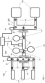
- Figures 1 shows a schematic of a top view of a diagnostic laboratory distribution system 100.
- Pre-analytic systems 110 are able to receive goods by an operator. In diagnostics labs these are usually tubes filled with a body fluid of a patient. These tubes are sorted, centrifuged and the quality of the body fluid is checked. The pre-analytic systems hand-over the goods 230 into the carriers 240.
- the carriers 240 transports the goods/tubes 230 on the transport plane 200 to analyzers 120.
- the analyzers 120 some part of the body fluid is sucked out of the tubes to be analyzed.
- the tubes 230 are transported by the carriers 240 on the transport plane 200 to the post-analytic stations 130.
- These post-analytic stations 130 have a sorting device to put the tubes 230 into carriers which are then transported into a fridge. If a further measurement is required for a special tube the post-analytic station 130 can retrieve the tube and put it again into a carrier 240, so that the tube can be transported again to an analyzer 120 which makes the required measurement.
- a transport system with transport plane 200 connects the pre-analytic systems 110, the analyzers 120 and the post-analytic stations 130, so that the carriers 240 can be transported moving on the transport plane 200.
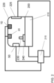
- Humidity sensors 10 and microbiological sensors 20 are distributed over the transport system. One possibility to fix these sensors is shown in Fig. 2 .
- the humidity sensors 10 and microbiological sensors 20 are fixed at a cover 220 over the transport plane 200. So these sensors are place in a tube like space bordered by the transport plane 200 and cover 220.
- microbiological sensors a real time bio aerosol sensors such as described in US20170209860 .
- Sensors to measure relative humidity are well known in the art and e.g. described in US5844138 .
- combinations of microbiological sensors with relative humidity sensors are known, so that the microbiological sensor 20 and the humidity sensor 10 can be realized in one device.
- control device 215 is shown only with its connection to the airflow generating devices 40.
- Other connections to the transport system, the sensors 10,20 and maybe also the pre-analytic systems 110, the analyzers 120, and the post-analytic devices 130 are omitted to keep an overview. These connections can be realized by an industry-bus standard cable based or with wireless communication. All the connections shown in Fig. 2 are also present for the embodiment shown in Fig. 1 for each respective device.
- FIG. 1 four airflow generating devices 40 are placed so that a laminar airflow can be generated.
- a negative pressure escape aperture 30 is installed in the cover 220. This allows generating a laminar airflow by one airflow generating device 40 in the region where the analyzers are connected to the transport plane 200.
- a laminar airflow will minimize the risk of cross contamination between tubes 230 transported by the carriers 240 on the transport plane 200.
- open tubes 230 are transported in such a diagnostic laboratory distribution system 100.
- a additional airflow generating device 40 is need for the branch to the respective pre-analytic system 110. This additional airflow generating device 40 is connected to the control device 215 via a wireless communication.
- a uv-generating device 50 is shown. This is placed at the side of the cover 220. In a further embodiment the uv-generating devices 50 are placed always with a microbiological sensor 20.
- Fig. 2 shows a heating element 225 connected to the cover 220 to heat the cover 220.
- the heating element 225 can be realized as discrete heating element at distinct positions at the cover 220 or as a distributed heating element.
- a distribute heating element can be realized with heating wires included in the cover material over the whole length of the cover 220.
- the heating element 225 will heat up the cover so that condensation of any liquid can be prohibited at the cover 220. This avoid droplets which can contaminate the filling of the tubes 230 transported over the transport plane 200.
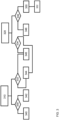
- Fig. 3 shows one embodiment of the method for a distribution system.
- step 310 the humidity of the air in the distribution system is controlled.
- the air is confined between a transport plane 200 and a cover 220 building some kind of tube.
- the signal of the humidity sensor 10 is sent to the control device 215.
- the control device 215 decides in step 332 whether the signal of the humidity sensor corresponding to the relative humidity in the air in the tube like air volume is above or below a predefined threshold. If the value is above the pre-defined threshold the control device 215 will sent in step 334 to the airflow generating devices 40 a signal to start the airflow and if the signal is below the threshold the control device 215 sends in step 346 a stop signal to the airflow generating devices and the airflow will be stopped.
- the control device 215 further decides in step 330 if the signal of the humidity sensor 40 measured in step 310 is above a second predefined value. If the signal is above the second predefined value the control device 215 will start in step 340 the heating element 225 of the cover 220. If the signal is below the second pre-defined value the control device 215 will sent in step 342 a stop signal to the heating element 225.
- step 320 the microbiological sensor 20 measure the microbiological contamination of the air in the tube like air volume between the transport plane 200 and the cover 220.
- step 334 the control device 215 decides if the value of the microbiological sensor 20 is above or below a pre-defined microbiological threshold. If the value is above the pre-defined microbiological threshold the control device will send in step 344 a start signal to the airflow generating devices 40. If the value is below the pre-defined microbiological threshold, the control device 215 will send in step 346 a stop signal to airflow generating device 40.
- the airflow generating device 40 will give to a start signal a higher priority than to any stop signal. For instance if the airflow generating device gets at the same time a start signal of step 344 and a stop signal form step 346 due to different outcomes of the values of the humidity sensor 10 in step 310 and the microbiological sensor in step 320 the airflow generating device 40 will start to generate the airflow.
- step 336 the control device 215 decides if the value of the microbiological sensor 20 measured in step 320 is above or below a second pre-defined microbiological threshold.
- control device 215 If the value is below the second pre-defined microbiological threshold the control device will sent in step 248 a stop signal to the uv-light generating devices 50. If the value is above the pre-defined second microbiological threshold the control device 215 sends in step 350 a signal to the drive means 210 to remove all goods 230 from the transport plane. If all goods are removed, the control device 215 sends in step 352 a start signal to the uv-light generating device 50. The control-device 215 gets feedback from the transport plane and the drive means so that the control device knows the position of all goods on the transport plane.
- the distribution system 100 is divided into separate portions so that in each portion the air in the tube like air volume is controlled independently for each portion by the control device 215.
- borders of the portions of the distribution system 100 are defined by the negative pressure escape apertures 30.
Claims (13)
- Diagnoselaborverteilungssystem (100), wobei das Verteilungssystem (100) Folgendes umfasstmehrere Träger (240), wobei die Träger (240) dafür ausgelegt sind, ein Gut oder mehrere Güter (230) zu tragen,eine Transportebene (200), wobei die Transportebene (200) dafür ausgelegt ist, die Träger (240) zu halten,Antriebsmittel (210), wobei die Antriebsmittel (210) dafür ausgelegt sind, die Träger (240) auf der Transportebene (200) zu bewegen, und eine Steuerungsvorrichtung (215) zur Steuerung der Antriebsmittel (210),wobei das Verteilungssystem (100) eine Abdeckung (220) für die Transportebene (200) umfasst,wobei das Verteilungssystem (100) Feuchtigkeitssensoren (10) zum Messen der Feuchtigkeit über der Transportebene (200), die mit der Steuerungsvorrichtung (215) verbunden sind, und Luftströmungserzeugungsvorrichtungen (40), die mit der Steuerungsvorrichtung (215) verbunden sind, umfasst;wobei die Luftströmungserzeugungsvorrichtungen (40) über dem Verteilungssystem (100) verteilt sind, um eine Luftströmung zwischen der Abdeckung (220) und der Transportebene (200) zu erzeugen,wobei die Steuerungsvorrichtung (215) dafür ausgebildet ist, die Luftströmungserzeugungsvorrichtungen (40) zu starten, wenn die Feuchtigkeitssensoren (10) eine Feuchtigkeit über einem vordefinierten Schwellenwert messen, wobei die Luftströmungserzeugungsvorrichtungen (40) eine laminare Luftströmung erzeugen.
- Verteilungssystem nach einem der vorstehenden Ansprüche, wobei die Steuerungsvorrichtung (215) dafür ausgebildet ist, die Luftströmungserzeugungsvorrichtungen (40) zu stoppen, wenn die Feuchtigkeitssensoren (10) einen Feuchtigkeitswert unter der vordefinierten Schwelle messen.
- Verteilungssystem nach einem der vorstehenden Ansprüche, wobei die Transportebene (200) des Verteilungssystems in Bahnen und Kreuzungen angeordnet ist, wobei die Abdeckung (220) des Verteilungssystems Unterdruckentweichungsöffnungen (30) umfasst, wobei die Unterdruckentweichungsöffnungen (30) an den Kreuzungen positioniert sind.
- Verteilungssystem (200) nach einem der vorstehenden Ansprüche, wobei die Abdeckung (220) Heizelemente (225) zum Heizen der Abdeckung (220) umfasst; wobei die Steuerungsvorrichtung (215) mit den Heizelementen (225) verbunden ist, wobei die Steuerungsvorrichtung (215) dafür ausgebildet ist, die Heizelemente (225) in Abhängigkeit einer vordefinierten zweiten Schwelle der Signale der Feuchtigkeitssensoren (10) zu starten und zu stoppen.
- Verteilungssystem (100) nach einem der vorstehenden Ansprüche, wobei das Verteilungssystem (100) mikrobiologische Sensoren (20) umfasst, die zwischen der Transportebene (200) und der Abdeckung (220) angeordnet und mit der Steuerungsvorrichtung (215) verbunden sind, und wobei die Steuerungsvorrichtung (215) dafür ausgebildet ist, die Luftströmungserzeugungsvorrichtungen (40) zu starten, wenn die Steuerungsvorrichtung ein Signal über einer vordefinierten biologischen Schwelle von dem mikrobiologischen Sensor (40) empfängt.
- Verteilungssystem (100) nach dem vorstehenden Anspruch, wobei die Steuerungsvorrichtung (215) dafür ausgebildet ist, die Luftströmungserzeugungsvorrichtungen (40) zu stoppen, wenn die Signale des mikrobiologischen Sensors (20) unter der vordefinierten biologischen Schwelle liegen.
- Verteilungssystem (100) nach den beiden vorstehenden Ansprüchen, wobei das Verteilungssystem eine UV-Lichterzeugungsvorrichtung (50) umfasst.
- Verteilungssystem (100) nach den drei vorstehenden Ansprüchen, wobei die Steuerungsvorrichtungen (215) mit der UV-Lichterzeugungsvorrichtung (50) verbunden ist und die UV-Lichterzeugungsvorrichtung (50) startet, wenn das Signal der mikrobiologischen Sensoren (20) über einer zweiten biologischen Schwelle liegt, und insbesondere die UV-Lichterzeugungsvorrichtungen stoppt, wenn das Signal der mikrobiologischen Sensoren unter der zweiten biologischen Schwelle liegt.
- Verfahren für ein Diagnoselaborverteilungssystem (100), wobei das Verteilungssystem (100) Folgendes umfasst:mehrere Träger (240), wobei die Träger (240) dafür ausgelegt sind, ein Gut oder mehrere Güter (230) zu tragen,eine Transportebene (200), wobei die Transportebene (200) dafür ausgelegt ist, die Träger (240) zu halten,Antriebsmittel (210), wobei die Antriebsmittel (210) dafür ausgelegt sind, die Träger (240) auf der Transportebene (200) zu bewegen, und eine Steuerungsvorrichtung (215) zur Steuerung der Antriebsmittel (210),wobei das Verteilungssystem (100) eine Abdeckung (220) für die Transportebene umfasst,wobei das Verteilungssystem (100) Feuchtigkeitssensoren (10), die mit der Steuerungsvorrichtung (215) verbunden sind, undLuftströmungserzeugungsvorrichtungen (40), die mit der Steuerungsvorrichtung (215) verbunden sind, umfasst;wobei die Luftströmungserzeugungsvorrichtungen (40) über dem Verteilungssystem (100) verteilt sind, um eine laminare Luftströmung zwischen der Abdeckung (220) und der Transportebene (200) zu erzeugen,wobei die Steuerungsvorrichtung (215) die Luftströmungserzeugungsvorrichtungen (40) startet, wenn die Feuchtigkeitssensoren (10) eine Feuchtigkeit über einem vordefinierten Schwellenwert messen.
- Verfahren für ein Verteilungssystem (100) nach dem vorstehenden Anspruch, wobei das Verteilungssystem (100) mikrobiologische Sensoren (20) umfassen, wobei die Steuerungsvorrichtung (215) die Luftströmungserzeugungsvorrichtungen (40) startet, wenn der mikrobiologische Sensor (20), der mit der Steuerungsvorrichtung (215) verbunden ist, ein Signal über einer vordefinierten mikrobiologischen Schwelle sendet, und die Luftströmungserzeugungsvorrichtungen (40) stoppt, wenn das Signal unter der vordefinierten mikrobiologischen Schwelle liegt.
- Verfahren für ein Verteilungssystem (100) nach dem vorstehenden Anspruch, wobei das Verteilungssystem UV-Lichterzeugungsvorrichtungen (50) umfassen, die mit der Steuerungsvorrichtung (215) verbunden sind, wobei die Steuerungsvorrichtung (215) die UV-Lichterzeugungsvorrichtungen (50) startet, wenn der mikrobiologische Sensor, der mit der Steuerungsvorrichtung (215) verbunden ist, ein Signal über einer zweiten vordefinierten mikrobiologischen Schwelle sendet, und die UV-Lichterzeugungsvorrichtungen (50) stoppt, wenn das Signal unter der zweiten vordefinierten mikrobiologischen Schwelle liegt.
- Verfahren für ein Verteilungssystem (100) nach dem vorstehenden Anspruch, wobei die Steuerungsvorrichtung (215) die Antriebsmittel (210) aktiviert, sodass alle Träger (240) aus einem Bereich der Transportebene (200), für die das Signal des mikrobiologischen Sensors (20) über der zweiten vordefinierten mikrobiologischen Schwelle liegt, bewegt werden, bevor die UV-Lichterzeugungsvorrichtungen (50) angeschaltet werden.
- Verfahren für ein Verteilungssystem (100) nach einem der drei vorstehenden Ansprüche, wobei ein Startsignal immer eine höhere Priorität hat als ein Stoppsignal der Luftströmungserzeugungsvorrichtungen (40).
Priority Applications (4)
| Application Number | Priority Date | Filing Date | Title |
|---|---|---|---|
| EP20383055.9A EP4008433B1 (de) | 2020-12-03 | 2020-12-03 | Verteilungssystem für diagnostisches labor |
| US17/452,781 US20220178957A1 (en) | 2020-12-03 | 2021-10-29 | Diagnostic laboratory distribution system |
| JP2021196513A JP7350043B2 (ja) | 2020-12-03 | 2021-12-02 | 診断ラボラトリ配送システム |
| CN202111460553.1A CN114594275A (zh) | 2020-12-03 | 2021-12-02 | 诊断实验室分配系统 |
Applications Claiming Priority (1)
| Application Number | Priority Date | Filing Date | Title |
|---|---|---|---|
| EP20383055.9A EP4008433B1 (de) | 2020-12-03 | 2020-12-03 | Verteilungssystem für diagnostisches labor |
Publications (2)
| Publication Number | Publication Date |
|---|---|
| EP4008433A1 EP4008433A1 (de) | 2022-06-08 |
| EP4008433B1 true EP4008433B1 (de) | 2024-01-24 |
Family
ID=73834413
Family Applications (1)
| Application Number | Title | Priority Date | Filing Date |
|---|---|---|---|
| EP20383055.9A Active EP4008433B1 (de) | 2020-12-03 | 2020-12-03 | Verteilungssystem für diagnostisches labor |
Country Status (4)
| Country | Link |
|---|---|
| US (1) | US20220178957A1 (de) |
| EP (1) | EP4008433B1 (de) |
| JP (1) | JP7350043B2 (de) |
| CN (1) | CN114594275A (de) |
Family Cites Families (19)
| Publication number | Priority date | Publication date | Assignee | Title |
|---|---|---|---|---|
| US3582144A (en) * | 1969-07-14 | 1971-06-01 | Air Preheater | Valve for air conveyor |
| JPH01148966A (ja) * | 1987-12-04 | 1989-06-12 | Hitachi Kiden Kogyo Ltd | 検体搬送装置 |
| JPH02157017A (ja) * | 1988-12-07 | 1990-06-15 | Fuji Photo Film Co Ltd | 乾燥空気生成装置および使用方法 |
| US5526705A (en) * | 1994-08-05 | 1996-06-18 | Tyler Limited Partnership | Automated work station for analyzing soil samples |
| US5844138A (en) | 1997-03-07 | 1998-12-01 | Veris Industries, Inc. | Humidity sensor |
| WO2001051929A1 (fr) * | 2000-01-12 | 2001-07-19 | Hitachi, Ltd. | Analyseur automatique et dispositif de transfert de portoir |
| US20090090022A1 (en) * | 2007-10-09 | 2009-04-09 | Hememics Biotechnologies, Inc. | Desiccation Chamber and Methods for Drying Biological Materials |
| DE102010028769A1 (de) * | 2010-05-07 | 2011-11-10 | Pvt Probenverteiltechnik Gmbh | System zum Transportieren von Behältern zwischen unterschiedlichen Stationen und Behälterträger |
| CN103518137B (zh) | 2011-05-13 | 2016-09-07 | 贝克曼考尔特公司 | 包括实验室产品传送元件的系统和方法 |
| EP2589966A1 (de) * | 2011-11-04 | 2013-05-08 | Roche Diagnostics GmbH | Laborprobenverteilungssystem und entsprechendes Betriebsverfahren |
| WO2016018910A1 (en) * | 2014-07-28 | 2016-02-04 | Douglas Scientific, LLC | Instrument for analyzing biological samples and reagents |
| JP2016176902A (ja) * | 2015-03-23 | 2016-10-06 | セイコーエプソン株式会社 | 電子部品搬送装置および電子部品検査装置 |
| EP3095739A1 (de) | 2015-05-22 | 2016-11-23 | Roche Diagniostics GmbH | Verfahren zum betrieb eines laborprobenverteilungssystems, laborprobenverteilungssystem und laborautomatisierungssystem |
| CN114814260A (zh) * | 2015-07-20 | 2022-07-29 | 安升达股份有限公司 | 自动化储库模块 |
| EP3139175B1 (de) * | 2015-09-01 | 2021-12-15 | Roche Diagnostics GmbH | Laborfrachtverteilungssystem, laborautomatisierungssystem und verfahren zum betrieb eines laborfrachtverteilungssystems |
| GB2546524B (en) | 2016-01-21 | 2019-10-30 | Nuwave Sensor Tech Limited | Method and apparatus for remote identification and monitoring of airborne microbial activity |
| EP3355064A1 (de) * | 2017-01-25 | 2018-08-01 | Roche Diagnostics GmbH | Laborprobenverteilungssystem und laborautomatisierungssystem |
| CN211323029U (zh) * | 2019-11-11 | 2020-08-25 | 云南中烟工业有限责任公司 | 一种加热不燃烧卷烟专用稠浆法再造烟叶的成型干燥系统 |
| US11184739B1 (en) * | 2020-06-19 | 2021-11-23 | Honeywel International Inc. | Using smart occupancy detection and control in buildings to reduce disease transmission |
-
2020
- 2020-12-03 EP EP20383055.9A patent/EP4008433B1/de active Active
-
2021
- 2021-10-29 US US17/452,781 patent/US20220178957A1/en active Pending
- 2021-12-02 JP JP2021196513A patent/JP7350043B2/ja active Active
- 2021-12-02 CN CN202111460553.1A patent/CN114594275A/zh active Pending
Also Published As
| Publication number | Publication date |
|---|---|
| EP4008433A1 (de) | 2022-06-08 |
| JP2022089188A (ja) | 2022-06-15 |
| US20220178957A1 (en) | 2022-06-09 |
| CN114594275A (zh) | 2022-06-07 |
| JP7350043B2 (ja) | 2023-09-25 |
Similar Documents
| Publication | Publication Date | Title |
|---|---|---|
| CN108408415B (zh) | 实验室样品分配系统和实验室自动化系统 | |
| US20220011335A1 (en) | Automated diagnostic analyzers having rear accessible track systems and related methods | |
| JP2731626B2 (ja) | 自動化分析計の校正方法 | |
| US7767147B2 (en) | Substrate for transporting liquid, a system for analysis and a method for analysis | |
| US8357543B2 (en) | Apparatus and method for handling fluids for analysis | |
| JP5993388B2 (ja) | 液体中の凝塊を検出する方法および装置、ならびに検査室オートメーションシステム | |
| JP6190390B2 (ja) | 高知能双方向多機能搬送体と物質分配及び搬送用統合自動化システム | |
| US9103807B2 (en) | Rack collecting unit and sample processing apparatus | |
| KR20140092377A (ko) | 분취기 시스템 및 작업흐름 | |
| JP2015507207A5 (de) | ||
| JPH11264828A (ja) | 検体搬送システム | |
| JPH05506512A (ja) | 温度制御チャンバを有する自動分析装置 | |
| US9229017B2 (en) | Sample processing apparatus, transport apparatus and non-transitory storage medium | |
| EP4008433B1 (de) | Verteilungssystem für diagnostisches labor | |
| CN103364573B (zh) | 被检物处理系统 | |
| JPH02266259A (ja) | 電気泳動装置 | |
| WO2018017759A1 (en) | Temperature controlled transport puck | |
| EP3833466B1 (de) | Verfahren und vorrichtung zur bestimmung der konzentration von analyten in vollblut | |
| JP2021043195A (ja) | 実験室輸送システム上においてキャリアを位置特定する方法およびシステム | |
| EP3385718A1 (de) | Verfahren zum betrieb eines laborprobenverteilungssystems, laborprobenverteilungssystem und laborautomatisierungssystem | |
| US20220371828A1 (en) | Method and distribution system to move carriers on a transport plane | |
| EP4234677A1 (de) | Analysegerät | |
| SE522755C2 (sv) | Anordning och metod för bestrålning av små partiklar för analys av partiklarnas kvalitet |
Legal Events
| Date | Code | Title | Description |
|---|---|---|---|
| PUAI | Public reference made under article 153(3) epc to a published international application that has entered the european phase |
Free format text: ORIGINAL CODE: 0009012 |
|
| STAA | Information on the status of an ep patent application or granted ep patent |
Free format text: STATUS: THE APPLICATION HAS BEEN PUBLISHED |
|
| AK | Designated contracting states |
Kind code of ref document: A1 Designated state(s): AL AT BE BG CH CY CZ DE DK EE ES FI FR GB GR HR HU IE IS IT LI LT LU LV MC MK MT NL NO PL PT RO RS SE SI SK SM TR |
|
| STAA | Information on the status of an ep patent application or granted ep patent |
Free format text: STATUS: REQUEST FOR EXAMINATION WAS MADE |
|
| 17P | Request for examination filed |
Effective date: 20221208 |
|
| RBV | Designated contracting states (corrected) |
Designated state(s): AL AT BE BG CH CY CZ DE DK EE ES FI FR GB GR HR HU IE IS IT LI LT LU LV MC MK MT NL NO PL PT RO RS SE SI SK SM TR |
|
| RIC1 | Information provided on ipc code assigned before grant |
Ipc: G01N 35/00 20060101ALI20230413BHEP Ipc: G01N 35/04 20060101ALI20230413BHEP Ipc: B01L 1/02 20060101AFI20230413BHEP |
|
| GRAP | Despatch of communication of intention to grant a patent |
Free format text: ORIGINAL CODE: EPIDOSNIGR1 |
|
| STAA | Information on the status of an ep patent application or granted ep patent |
Free format text: STATUS: GRANT OF PATENT IS INTENDED |
|
| GRAJ | Information related to disapproval of communication of intention to grant by the applicant or resumption of examination proceedings by the epo deleted |
Free format text: ORIGINAL CODE: EPIDOSDIGR1 |
|
| GRAP | Despatch of communication of intention to grant a patent |
Free format text: ORIGINAL CODE: EPIDOSNIGR1 |
|
| INTG | Intention to grant announced |
Effective date: 20230606 |
|
| INTG | Intention to grant announced |
Effective date: 20230627 |
|
| INTG | Intention to grant announced |
Effective date: 20230704 |
|
| GRAS | Grant fee paid |
Free format text: ORIGINAL CODE: EPIDOSNIGR3 |
|
| GRAA | (expected) grant |
Free format text: ORIGINAL CODE: 0009210 |
|
| STAA | Information on the status of an ep patent application or granted ep patent |
Free format text: STATUS: THE PATENT HAS BEEN GRANTED |
|
| AK | Designated contracting states |
Kind code of ref document: B1 Designated state(s): AL AT BE BG CH CY CZ DE DK EE ES FI FR GB GR HR HU IE IS IT LI LT LU LV MC MK MT NL NO PL PT RO RS SE SI SK SM TR |
|
| REG | Reference to a national code |
Ref country code: GB Ref legal event code: FG4D |
|
| REG | Reference to a national code |
Ref country code: CH Ref legal event code: EP |
|
| REG | Reference to a national code |
Ref country code: DE Ref legal event code: R096 Ref document number: 602020024805 Country of ref document: DE |
|
| REG | Reference to a national code |
Ref country code: IE Ref legal event code: FG4D |