EP4007904B1 - Partikelsensor und messverfahren - Google Patents
Partikelsensor und messverfahren Download PDFInfo
- Publication number
- EP4007904B1 EP4007904B1 EP20751261.7A EP20751261A EP4007904B1 EP 4007904 B1 EP4007904 B1 EP 4007904B1 EP 20751261 A EP20751261 A EP 20751261A EP 4007904 B1 EP4007904 B1 EP 4007904B1
- Authority
- EP
- European Patent Office
- Prior art keywords
- particles
- charge
- received
- electrometer
- positive
- Prior art date
- Legal status (The legal status is an assumption and is not a legal conclusion. Google has not performed a legal analysis and makes no representation as to the accuracy of the status listed.)
- Active
Links
Images


Classifications
-
- G—PHYSICS
- G01—MEASURING; TESTING
- G01N—INVESTIGATING OR ANALYSING MATERIALS BY DETERMINING THEIR CHEMICAL OR PHYSICAL PROPERTIES
- G01N15/00—Investigating characteristics of particles; Investigating permeability, pore-volume or surface-area of porous materials
- G01N15/06—Investigating concentration of particle suspensions
- G01N15/0656—Investigating concentration of particle suspensions using electric, e.g. electrostatic methods or magnetic methods
-
- G—PHYSICS
- G01—MEASURING; TESTING
- G01N—INVESTIGATING OR ANALYSING MATERIALS BY DETERMINING THEIR CHEMICAL OR PHYSICAL PROPERTIES
- G01N1/00—Sampling; Preparing specimens for investigation
- G01N1/02—Devices for withdrawing samples
- G01N1/22—Devices for withdrawing samples in the gaseous state
-
- G—PHYSICS
- G01—MEASURING; TESTING
- G01N—INVESTIGATING OR ANALYSING MATERIALS BY DETERMINING THEIR CHEMICAL OR PHYSICAL PROPERTIES
- G01N15/00—Investigating characteristics of particles; Investigating permeability, pore-volume or surface-area of porous materials
- G01N15/02—Investigating particle size or size distribution
- G01N15/0266—Investigating particle size or size distribution with electrical classification
-
- G—PHYSICS
- G01—MEASURING; TESTING
- G01N—INVESTIGATING OR ANALYSING MATERIALS BY DETERMINING THEIR CHEMICAL OR PHYSICAL PROPERTIES
- G01N33/00—Investigating or analysing materials by specific methods not covered by groups G01N1/00 - G01N31/00
- G01N33/0004—Gaseous mixtures, e.g. polluted air
-
- G—PHYSICS
- G01—MEASURING; TESTING
- G01N—INVESTIGATING OR ANALYSING MATERIALS BY DETERMINING THEIR CHEMICAL OR PHYSICAL PROPERTIES
- G01N1/00—Sampling; Preparing specimens for investigation
- G01N1/02—Devices for withdrawing samples
- G01N1/22—Devices for withdrawing samples in the gaseous state
- G01N1/2202—Devices for withdrawing samples in the gaseous state involving separation of sample components during sampling
- G01N2001/222—Other features
- G01N2001/2223—Other features aerosol sampling devices
-
- G—PHYSICS
- G01—MEASURING; TESTING
- G01N—INVESTIGATING OR ANALYSING MATERIALS BY DETERMINING THEIR CHEMICAL OR PHYSICAL PROPERTIES
- G01N15/00—Investigating characteristics of particles; Investigating permeability, pore-volume or surface-area of porous materials
- G01N2015/0038—Investigating nanoparticles
-
- G—PHYSICS
- G01—MEASURING; TESTING
- G01N—INVESTIGATING OR ANALYSING MATERIALS BY DETERMINING THEIR CHEMICAL OR PHYSICAL PROPERTIES
- G01N15/00—Investigating characteristics of particles; Investigating permeability, pore-volume or surface-area of porous materials
- G01N2015/0042—Investigating dispersion of solids
- G01N2015/0046—Investigating dispersion of solids in gas, e.g. smoke
-
- G—PHYSICS
- G01—MEASURING; TESTING
- G01N—INVESTIGATING OR ANALYSING MATERIALS BY DETERMINING THEIR CHEMICAL OR PHYSICAL PROPERTIES
- G01N15/00—Investigating characteristics of particles; Investigating permeability, pore-volume or surface-area of porous materials
- G01N15/10—Investigating individual particles
- G01N15/14—Optical investigation techniques, e.g. flow cytometry
- G01N2015/1486—Counting the particles
Definitions
- the invention relates to the field of particle sensors for measuring size and concentration properties of particles in gases.
- Aerosols consist of solid or liquid particles suspended in a gaseous medium. Aerosols can adversely affect the climate, environment and human health and are commonly emitted as a byproduct of combustion or industrial processes. Aerosol particles may also be engineered for the production of materials with unique properties. Accordingly, there is a demand for sensors which can reliably measure and characterise aerosols.
- the lung deposited surface area is roughly proportional to Nd, the first moment of a particle size distribution, where N is the number of particles and d is their diameter. This arises from the fact that, whilst the particle surface area is approximately proportional to Nd 2 , the probability of particle deposition in the lung for submicron particles is approximately proportional to the reciprocal of their diameter, d -1 within the diameter range of about 10 to 400 nm It is therefore useful to obtain a measurement which is roughly proportional to Nd.
- mobility-equivalent diameter is an appropriate representation of particle diameter in this discussion.
- the present invention relates to the field of particle sensors in which particles are received in a gas sample, electrically charged in an electrical charge conditioning stage, and then analysed by electrometric means.
- a known class of sensors charges received particles in a gas so that they become either all positively or all negatively charged via collisions with correspondingly charged gas ions. This is referred to as unipolar diffusion charging, reflecting the fact that the received particles which become charged acquire either all positive or all negative charges.
- the charges on the particles can then be detected using an electrometer, and arrangements of electrodes have been used to generate controlled electrical fields to select charged particles in different size and/or electrical mobility ranges. Examples of such sensors are known from EP1655595 A1 or WO2019/012185 A1 .
- received particles can be charged using photoelectric ionisation. Again, this provides unipolar (positive) charging of received particles which may subsequently be detected by electrometric means (e.g. a Faraday cage).
- electrometric means e.g. a Faraday cage
- Particle sensors based on unipolar diffusion charging or photoelectric charging of received particles are known. However, it is essential that the charging of the received particles is consistent. The rate of generation of charged ions and the time for which the received particles remain mixed with the charged ions may each have a critical effect on measurement accuracy and repeatability.
- Such devices typically measure currents associated with the product of the number of charges per unit volume and their flow rate, either directly or indirectly via collection, or via charge induction, and so uncontrolled variations in charging lead to errors in measurement. As a result, such devices require methods of generating ions which are often expensive and/or bulky, and in which the total charge concentration depends on the details of the particular hardware used to produce the charges.
- Devices based on unipolar charging are also known to output a current which departs somewhat from Nd, the first moment of particle size distribution, for example some devices output a current which is closer to Nd 1.1 (proportional to diameter, d, to the power of 1.1).
- the invention seeks to provide a particle sensor which is reliable, relatively simple and/or low cost, and which provides a particle measurement which is useful for environmental monitoring.
- Some unipolar chargers may in fact generate ozone or otherwise be environmentally deleterious and the invention also seeks to avoid this.
- the invention makes use of bipolar diffusion charging, a process in which a mixture of positive and negatively charged ions is formed in a gas, typically air. Received particles then acquire positive and negative charges concurrently as a result of collision with these ions.
- Bipolar diffusion charging is used in everyday smoke detectors.
- the positively and negatively charged ions are generated by radiation from a suitable radioactive material which charges clean air in a reference cell, and surrounding air and any surrounding particles in a sample chamber.
- the movement of the resulting ions along a potential gradient enables a current to pass between opposing electrodes associated with the reference and sample chamber.
- Smoke particles block the passage of ions, reducing the current, so that a decrease in current is indicative of the presence of smoke particles.
- the smoke particles are thereby detected indirectly, and not by direct electrometric measurement of charge on the smoke particles.
- Bipolar diffusion chargers are used in scanning mobility particle sizers (SMPS). In these devices, received particles within a specific electrical mobility range are selected using a differential mobility analyser and detected by a condensation particle counter. These devices can be very accurate and provide detailed particle size information, but are expensive and complex.
- the bipolar diffusion charger is used as a charge neutraliser, designed to reduce any residual charges in the particle stream to a known steady state value. In the bipolar diffusion charging process, both positive and negative ions (charged gas molecules) briefly contact and transfer charge to the received particles.
- a particle sensor as defined in claim 1.
- the particle sensor comprising an inlet for receiving a gas sample for analysis, a bipolar diffusion charger configured to charge particles within the received gas sample by the collision of the received particles with and transfer of charge from both positive and negative ions concurrently, and at least one electrometer configured to detect the charge of received particles thereby charged.
- the at least one electrometer may be configured to detect the charge of some or all of the received particles thereby charged.
- the particle sensor further comprises a circuit configured to receive signals from the at least one electrometer and calculate at least one parameter of the concentration and/or size of the received particles in the received gas sample.
- the circuit may comprise a hardware processor.
- the bipolar diffusion charger typically comprises a chamber within which the mixture of received particles and the positive and negative ions is formed.
- the received gas sample may flow through the chamber.
- the positive and negative ions may be generated within the chamber.
- the positive and negative ions may be generated outside the chamber, such as in a separate chamber (e.g. an ion generation chamber), and pass into the chamber, for example by convection or electrostatic forces (e.g. through a conduit).
- the bipolar diffusion charger may comprise a radioactive material, such as Americium-241, and a gas, such as air, which is typically the received gas sample. In such chargers, radiation from the radioactive material (alpha particles in the case of Americium-241) collides with gas molecules and creates both positive and negative gas ions within the gas concurrently.
- the bipolar diffusion charger may be based on another principle.
- the bipolar diffusion charger may comprise an x-ray source or even two unipolar chargers of opposite polarity which charge the same volume of gas concurrently.
- the positive and negative ions are gas ions.
- the ions are formed by ionisation of gaseous molecules within the chamber of the bipolar diffusion charger or elsewhere. There are typically an equal number of positive and negative ions produced during formation of the ions therefore the gas retains an overall neutral charge.
- the gas retains an overall neutral charge or nearly neutral charge in the bipolar diffusion charger, a charger used to charge particles.
- the positive and negative ions diffuse within the gas, and are affected also by electrostatic forces, and so collide with and transfer charges to the received particles within the bipolar diffusion charger. The received particles acquire a range of charges which, once a steady state is reached, are as described originally by N. A. Fuchs in 1963 (Geofisica pura e applicata, September 1963, Vol.
- bipolar diffusion chargers leave particles with a slight overall charge, typically (e.g. in air) a negative charge. Without wishing to be bound by theory we believe that this results from the higher mobility of the negative ions relative to positive ions. This means that the charge on the bipolar charged received particles can be detected with an electrometer without requiring to separate the positive and negative charged received particles. Accordingly, the net charge of received particles thereby charged is measured, i.e. the difference between the total positive charge and total negative charge of received particles thereby charged.
- the resulting charge distribution as a function of particle diameter has been predicted since 1963, this has only recently been measured in detail. Further, we have observed experimentally that the net charge measured is very stable and is insensitive to variations in the rate of charge generation within the bipolar diffusion charger. Thus, it is not necessary to measure the rate of charge generation within the bipolar diffusion charger or to control for variations with time in charge generation or the residence time of the received particles in a charging zone, provided that these parameters exceed at least a minimum threshold. As a result, the received particles can be charged such as to be suitable for detection with an electrometer reliably in a simple device.
- the overall net charge at steady state arises from the different mobility of the positive and negative ions (in particular the higher mobility of negative ions relative to positive ions when the bipolar diffusion charger uses air as the source of positive and negative ions).
- the charging of the received particles by a bipolar diffusion charger moves towards a steady state.
- the person skilled in the art can specify a bipolar diffusion charger which is sufficiently effective to ensure that charging is close to steady state and we have found that typical radiation sources used in domestic smoke alarms have more than sufficient activity for use in the detection of typical levels of aerosols in urban environments. It may be that a steady state is reached. Nevertheless, this is not essential, and it may be that a steady state is not reached.
- the mean net charge on bipolarly charged particles at steady state is proportional to the first moment of the particle diameter distribution, Nd, where N is a numerical count per unit volume and d is the particle diameter, over at least the range of 50 to 1000 nm diameters.
- the current measured by the at least one electrometer is approximately a measurement of the product of the number of particles to be detected by the electrometer per second and the mean net charge of those particles.
- the circuit divides the measured current by a measured or known air volume flow rate, giving a first moment of charge.
- this first moment of charge measurement is proportional to the lung deposited surface area (LDSA) concentration (LDSA per unit volume of gas) of the received particles in the received gas sample which, as described above, is a very relevant measurement.
- LDSA lung deposited surface area
- the at least one electrometer will typically also measure the charge of any remaining free ions which have been mixed with the received particles in the bipolar diffusion charger, if present. Although not essential it would be preferable to remove remaining free ions so that the at least one electrometer measures charges only from the received particles thereby charged.
- the particle sensor comprises an ion trap between the bipolar diffusion charger and at least one said electrometer (at least one, or each, electrometer of the said at least one electrometer), configured to separate free (e.g. flowing) positive and negative ions mixed with the received particles in (e.g. the chamber of) the bipolar diffusion charger) from the received particles before they reach at least one said electrometer.
- free positive and negative ions generated by the bipolar diffusion charger or found in the initial gas sample
- the ion trap is downstream of the bipolar diffusion charger and upstream of at least one said electrometer (where downstream refers to further along a gas flow path from an inlet through the bipolar diffusion charger to the at least one electrometer and upstream refers to the opposite direction).
- the ion trap typically removes the free positive and negative ions (generated by the bipolar diffusion charger), which have been mixed with the received particles, from the received particles (whether charged or uncharged) before the received particles (whether charged or uncharged) reach at least one said electrometer. Very small ( ⁇ 5 nm) received particles may also be removed, but larger received particles will remain in the flow.
- the ion trap may comprise a pair of spaced apart electrodes, which are oppositely charged during use. They may be spaced apart within (e.g. located on opposite walls of) a chamber or tube through which gas passes between the bipolar diffusion charger and the at least one electrometer. Nevertheless, the ion trap may have a different form, for example it may comprise an ion selective filter membrane. It may be that the current generated from the capture of ions at either of the spaced apart electrodes is not used to determine an output of the sensor (and typically is not measured).
- the current generated from the capture of ions at either of the spaced apart electrodes is measured and the controller processes the current to determine one or more parameters of the charge flux (for example parameters of the charge generation) in the bipolar diffusion charger, or to detect an excess of particles, for example to detect smoke in the event of a fire.
- the controller processes the current to determine one or more parameters of the charge flux (for example parameters of the charge generation) in the bipolar diffusion charger, or to detect an excess of particles, for example to detect smoke in the event of a fire.
- the current at the ion trap need not be monitored.
- the ion trap may also comprise an electrometer, in which case there is at least one further electrometer (downstream of the ion trap).
- the at least one electrometer may comprise an electrometer associated with the ion trap and one or more electrometers which are downstream of the ion trap.
- the at least electrometer may be one or more electrometers, for example an electrometer associated with the ion trap and one or more further electrometers.
- the ion trap is configured to separate the ions from the mixture of gas and received particles by diffusion. They make use of the much higher diffusion coefficient of the gas ions of the bipolar diffusion charger than the received particles.
- a simple example would be a tube formed of material which is porous to ions through which the mixture flows. Ions may diffuse out through the walls of the tube while the received particles would more closely follow a flow path through the tube and so be less likely to be lost to the walls of the tube.
- another simple example would be a tube formed of electrically conductive material through which the mixture flows. Ions may diffuse to, collide with, and transfer charge to the walls of the tube which would conduct away the electrical charge from the ions.
- the received particles and the ions may flow together through the conduit.
- the additional time required for the received particles to pass through the conduit mixed with positive and negative ions facilitates equilibration between the particles and ions in the gas.
- One or more or all of the electrometers may be a charge-summing detector. They produce an output which is dependent on (typically proportional to) the sum of the charge per unit time which is detected by the one or more electrometers (current).
- One or more or all of the electrometers may for example comprise a Faraday cup or a wire grid.
- the one or more electrometers measure the current produced by all of the particles which have been received through the inlet and charged by the bipolar diffusion charger.
- the resulting particles are measured by the at least one electrometer without positive and negatively charged received particles being separated from each other.
- the charged particles received and measured by the at least one electrometer typically comprise a mixture of positively, negatively and neutrally charged particles, with a net overall charge (typically a net overall negative charge).
- the particles which are received, bipolarly charged and measured by the at least one electrometer concurrently have a wide range of particle mobilities (i.e. mobility diameters), for example, particle mobilities varying by a factor of at least 10.
- the sensor typically does not include a differential mobility analyser and/or a condensation particle counter.
- the particle sensor such as the first example of the sensor, could be used in combination with a particle counter (which derives N, the number of particles) which could be divided into the output of the circuit/measured current to obtain an estimate of mean particle diameter (which can be expressed as an estimate of mean particle mobility diameter or geometrical diameter as required).
- a particle counter which derives N, the number of particles
- Other embodiments of the particle sensor such as the second example of the sensor, can independently obtain an estimate of both the number of particles (N) and mean particle diameter (d).
- the distribution of particle charges arising from bipolar diffusion charging that achieves steady state is also stable and insensitive to variations in the rate of charge generation within the bipolar diffusion charger.
- some or all of the positively charged particles and/or some or all of the negatively charged particles are separated from particles of different polarity and/or separated from particles of the opposite polarity and/or separated from the other particles which were exposed to ions from the bipolar diffusion charger, and the charge of the separated particles is measured.
- this segregation can yield a larger signal and/or a signal which is less sensitive to variations to the mobilities of charging ions than other embodiments, such as the net aerosol current.
- Such embodiments may also generate different or multiple measurement signals, thus allowing the particles to be further characterized.
- separating some or all of the positively and/or negatively charged particles from particles of opposite polarity we refer to separating some or all of the positively charged particles from negatively charged particles, and optionally also from neutrally charged particles, and/or separating some or all of the negatively charged particles from positively charged particles and optionally also from neutrally charged particles.
- separating some or all of the positively and/or negatively charged particles from particles of different polarity we refer to separating some or all of the positively charged particles from both negatively and neutrally charged particles and/or separating some or all of the negatively charged particles from both positively and neutrally charged particles.
- the received particles thereby charged are separated by charge polarity, typically using a potential gradient formed between two or more electrodes, prior to or during the step of charge measurement by at least one said electrometer.
- the separation is by charge polarity, rather than by particle diameter.
- measurements of the charge of only positive charged particles and/or only negatively charged particles, from the received particles which have been charged by the bipolar diffusion charger may be obtained.
- the particles will typically have a wide range of particle mobilities (i.e. mobility diameters) and/or electrical mobilities (i.e. electrical mobility diameters), for example, the separated particles may have particle mobilities and/or electrical mobilities varying by a factor of at least 5, or at least 10.
- some or all of the received particles of the same polarity thereby charged may be separated from particles of different and/or opposite polarity.
- all positively charged particles, or at least positively charged particles with electrical mobilities higher than a threshold may be separated from other particles and/or all negatively charged particles, or at least negatively charged particles with electrical mobilities higher than a threshold may be separated from other particles.
- positively charged particles with electrical mobilities higher than the threshold or negatively charges particles with electrical mobilities higher than the threshold are separated out.
- the separation functions each act as a low pass filter in terms of particle electrical mobility (whereby the particles which have an electrical mobility higher than the threshold are detected (and typically also captured), whilst the remainder are not detected (and typically pass through the device).
- the separation is typically not a band pass filter which selects particles in a band of electrical mobilities.
- the separation of particles by charge polarity may take place before, after or during the step of removing free ions using the ion trap, where the ion trap is present. Measurements are thereby obtained of the sum of the charge of the separated positively charged particles and/or the sum of the charge of the separated negatively charged particles.
- the sums of charges are typically expressed as currents.
- At least one electrometer measures the charge of only positively charged or only negatively charged particles, rather than the net charge of the unseparated mixture of positively and negatively charged particles (although this net charge may also be measured).
- the focus is no longer on the small (typically negative) net charge of particles which have been subject of the equilibrium processes of bipolar diffusion charging, we have found that the sum of positive charges and/or the sum of negative charges of particles thereby produced, individually and in combination (summing the absolute value of the sum of positive charges and the absolute value of the sum of negative charges), gives larger signals and/or more information, while still benefiting from bipolar diffusion charging being an equilibrium process which is relatively insensitive to variations in the rate of charge generation within the bipolar diffusion charger.
- the measured current of only positively charged particles, only negatively charged particles, or the combination of these is less sensitive to variations to the ion-mobility ratio than other embodiments, such as the net charge of unseparated positively charged and negatively charged particles (referred to herein as the net aerosol current).
- the net aerosol current is less sensitive to variations to the ion-mobility ratio than other embodiments, such as the net charge of unseparated positively charged and negatively charged particles (referred to herein as the net aerosol current).
- changing the ion mobility ratio from 0.875 to 0.795 changes the net aerosol current by 72% on average for particles from 2 to 903 nm, however the same ion mobility ratio change affects the total aerosol current by only 3% on average.
- the separation may result in a stream of positively charged particles and/or a stream of negatively charged particles, from the received particles which have been charged by the bipolar diffusion charger.
- the separated positively charged and/or negatively charged particles may be some or all of the positively charged and/or negatively charged particles which have been charged by the at least one bipolar diffusion charger.
- at least one electrometer is configured to detect the charge of the positively charged particles and at least one electrometer is configured to detect the charge of the negatively charged particles.
- the stream of positively charged particles and the stream of negatively charged particles may be separate and their charges may be detected by separate electrometers. However, it may be that a stream of positively charged particles and a stream of negatively charged particles are generated alternately. In this case, the charge of each may be detected by the same (or different) one or more electrometers.
- one or more electrometers is configured to both separate the positively and/or negatively charged particles from particles of different and/or opposite polarity and to (independently) measure the charge of the (thereby separated) positively charged particles and/or the negatively charged particles.
- one or more electrometer comprises first and second electrodes and is configured to apply a positive potential to the first electrode and a negative potential to the second electrode, to thereby attract the positively charged particles, of the received charged particles, to the second electrode and the negatively charged particles, of the received charged particles, to the first electrode, to thereby separate the positively charged particles and the negatively charged particles, and further comprises at least one current sensor to measure the current of negative charges received at the first electrode and/or the current of positive charges received at the second electrode.
- an electrometer may be configured to both separate the positively and negatively charged received particles (which have been charged by the bipolar diffusion charger) and to independently determine the charges of the positively charged particles and the negatively charged particles.
- the circuit may calculate the at least one parameter of the concentration and/or size of the received particles in the received gas sample taking into account one or more of:
- total aerosol current The sum of the absolute value of the measured charges, abs[i + ]+abs[i - ] (the "total aerosol current") can be substantially greater that the net charge, abs[i + ]-abs[i - ] (the "net aerosol current"). Furthermore, due to the equilibrium processes of bipolar diffusion charging, this sum is relatively insensitive to changes in the parameters of the bipolar diffusion charger.
- the circuit may independently calculate the total number concentration and average size of particles in the received particles from two or more of measurements (i) - (iv) above. This is possible as two or more independent signals are processed.
- the circuit may calculate the lung deposited surface area of the received particles, typically based on measurement (iv), or two or more of measurements (i) - (iii).
- the circuit may calculate the ion mobility ratio of the bipolar diffusion charger from two or more of measurements (i) - (iv) above and/or an ion trap current, while measuring particles of known or measured size or concentration, and use these measurements as a calibration parameter. There is therefore one fewer unknown than is required to determine the ion mobility ratio if only the net aerosol current (net current of unseparated positive and negatively charged particles) is measured.
- the one or more electrometers may be flow-through electrometers, which measure charge in gas (e.g. air) passing through the electrometer.
- the particles may be retained within the electrometer.
- the particle sensor may be a flow-through sensor.
- the particle sensor may comprise a body defining the inlet and typically also an outlet.
- the particle sensor may comprise or be used with an air flow speed sensor.
- the sensor may comprise or may be used with, an air flow regulator, such as a fan or an air pump, to regulate the speed at which received particles are charged and passed through the electrometer. This enables measurements per unit volume to be calculated.
- the sensor may comprise, or be used with an air speed sensor (which may function by detecting the speed at which received particles move through the sensor, for example, optically), to thereby enable measurements per unit volume of air to be made. This may enable an air flow regulation device to be omitted giving a simpler device. Air may flow through the device by convection. It is possible for the device to have an inlet but no outlet and to be based on diffusion.
- the received particles are aerosols. It may be that the received particles have a diameter of at least 10 nanometers. It may be the received particles have a diameter of at least 50 nanometers. It may be that the received particles comprise PM 2.5 .
- the received particles may be particulates.
- the received particles may be particulate matter. It may be that the received particles comprise or are soot particles.
- the bipolar diffusion charger comprises an amount of a radioactive element with an activity of at least 5 kBq. It may be that the bipolar diffusion charger comprises an amount of a radioactive element with an activity of less than 500 kBq or less than 50 kBq.
- Americium-241 sources with an activity in the range of 5 to 50 kBq are in common use in smoke detectors and do not require special handling procedures for consumers.
- the gas molecules which are charged by the bipolar diffusion charger are received with the gas sample, for example they may be air molecules where the gas sample is a sample of atmospheric air.
- the bipolar diffusion charger comprises an ionisable material, typically a solid, which is ionised within the bipolar diffusion charger.
- the ionisable material may be a material which is ionisable by radiation, typically by radiation from the radioactive material, where present.
- the ionisable material may be a gas or a solid or a liquid sacrificial material, which is typically stationary.
- the ionisable material may be located within the bipolar diffusion chamber and/or within a chamber containing the radioactive material.
- the ions formed in the bipolar diffusion charger may come at least in part from the ionisable material. This enables the mobility of ions within the bipolar diffusion charger to be regulated.
- the ionisable material may comprise a salt, for example sodium chloride.
- the ionisable material may be a siloxane.
- one or more chargeable gaseous species are introduced into the bipolar diffusion charger, either as part of the gas sample (for example introduced into the gas sample) or separately. Again, this enables the mobility of ions within the bipolar diffusion charger to be regulated, for example to maximise the ratio of the mobility of ions of one polarity to ions of the other polarity or to optimise the consistency of charging or the speed of reaching a steady state (equilibrium).
- the sensor may comprise or be used with a temperature regulator (e.g. one or more heating or cooling elements) to regulate the temperature of gas within the bipolar diffusion charger (for example to heat or cool the gas, or to obtain a target temperature).
- a temperature regulator e.g. one or more heating or cooling elements
- This may enable ion mobility to be regulated or independently, this may be used to increase the electrometer current since electrometer current proportional to the net charge on the particles is a linear function of temperature as can be seen from Equation 7.
- the sensor may also comprise or be used with a humidity regulator to regulate the humidity of gas within the bipolar diffusion charger (typically by regulating the humidity of gas upstream of the bipolar diffusion charger).
- One or more electrical fields may be applied within the bipolar diffusion charger (using a plurality of electrodes) to enhance bipolar diffusion charging, for example by attracting the ions of the bipolar diffusion charger towards the received particles or vice versa.
- Bipolar diffusion charging may also be enhanced by advection, for example using an air flow generator configured to generate advection within the sensor.
- An advantage of the invention is that the net, positive, negative or total charge on the bipolarly charged received particles has a low sensitivity to variations in the absolute rate of charge generation in the bipolar diffusion charger. It may be that parameters of charge flux of ions within the bipolar diffusion charger are not measured. It may be that the rate of charge generation within the bipolar diffusion charger is not measured. Nevertheless, in some embodiment, parameters of charge flux of ions within the bipolar diffusion charger (e.g. the rate of charge generation) may be measured.
- the sensor may comprise a current sensor configured to measure the current which flows between oppositely charged electrodes in the ion trap. The measured current may be processed and compared with a threshold indicative of a predetermined acceptable rate of charge generation.
- the measured current may be processed to determine one or more properties of the particle concentration and/or size.
- the processing may also take into account the at least one electrometer current used to measure mean particle charge, or the efficiency of the ion source or properties of the ions and may take into account the at least one electrometer current (used to measure mean particle charge / the first moment of particle size distribution).
- the rate of charging of gas molecules by the ion source, or the absorbance of ions by the ion trap is modulated, for example on or off.
- the one or more electrometers will output a modulated signal.
- the measurement from one or more electrometers may be (correspondingly) demodulated (i.e. the underlying unmodulated signal may be extracted from the modulated signal). This reduces the effects of an offset, thereby accounting for signal drift over time.
- Modulation may also be used to quantify signal drift.
- a radiation source is moved, or a cover for the radiation source is moved (e.g. a shutter opened and closed), or an electric field which regulated the movement of generated ions is modulated.
- the potential difference between electrodes within the ion trap may be modulated (e.g. switched on and off). Modulation may also reduce clogging of the device with received particles.
- a method of measuring a parameter of the size and/or concentration of particles in a gas sample for analysis comprising the steps of receiving a gas sample comprising particles, charging received particles in the gas sample by bipolar diffusion charging thereby charging the particles by the collision of received particles with and the transfer of charge from both positive and negative ions concurrently, and using at least one electrometer to detect the net charge of received particles which are thereby charged.
- Bipolar diffusion charging creates a mixture of positive and negative ions (charged gas molecules).
- the positive and negative ions may be generated by collisions between molecules and radiation (typically alpha or beta particles) from a radioactive material.
- the positive and negative ions consist of gas molecules (typically gas molecules within the received sample) although in some embodiments a solid, gas or liquid material (which is typically present in or introduced into the bipolar diffusion charger) may be ionised.
- the received particles (received in the gas sample, which may be drawn into the sensor) are charged by transfer from the resulting positive and negative ions.
- Positive and negative ions are both present and so collisions with and transfer of charge from both positive and negative ions (to received particles) takes place concurrently. This arises as the received particles collide with the positive and negative ions.
- the charging of the received particles by the positive and negative ions is an equilibrium process. It may be that the charging does, or in some embodiments does not, reach a steady state (equilibrium). As a result of the charging, the received particles have a distribution of charges, with a net charge, which is typically a net negative charge.
- the method comprises separating the received particles (which have passed through the bipolar diffusion charger) from the free positive and negative ions (formed during bipolar diffusion charging, e.g. from collisions between gas molecules and radiation), passing the received particles and said free positive and negative ions through an ion trap which removes the positive and negative ions, before the received particles reach at least one said electrometer.
- the method comprises separating free (e.g. remaining) positive and negative ions from the mixture of received particles and positive and negative ions formed during bipolar diffusion charging.
- the positive and negative ions are removed (from the received particles) before the received particles reach the or each of the at least one electrometer, although it is possible for the ion trap to comprise an electrometer, in which case the at least one electrometer comprises an electrometer associated with the ion trap and at least one further electrometer (downstream of the ion trap).
- the bipolar diffusion charger e.g. in a chamber of the bipolar diffusion charger
- the ion trap typically separates free positive and negative ions in this mixture (e.g. which remain in the flow) from the received particles, before the received particles reach at least one said electrometer.
- the ions are typically removed by the ion trap and the charge of the received particles is detected by at least one said electrometer (downstream of the ion trap).
- the received particles may be separated from the positive and negative ions by an electrical potential gradient applied between electrodes.
- the current generated from the capture of ions at the electrodes is monitored to measure the rate of ionisation or to detect the presence of an amount or size of particles exceeding a threshold or to detect smoke (from a decrease in the current between the electrodes which exceeds a threshold).
- the received particles may be separated from free positive and negative ions by other means, for example by diffusion separation if the received particles are sufficiently large (for example greater than approximately 50 nm in diameter).
- One or more electrometers may be a charge summing electrometer.
- One or more electrometers may output a current related to (typically proportional to, for example equal and opposite to) the rate of charge flow into or through the electrometers.
- One or more electrometers may measure the rate of charge flow into or through the electrometers.
- the method may comprise directing the received particles and the ions through a conduit, before they are separated (e.g. by the ion trap) to provide time for equilibration.
- the flow of gas through bipolar diffusion charging to the one or more electrometers may be regulated by an air flow regulator (e.g. a fan).
- the method may comprise measuring air flow speed.
- the output from the one or more electrometers may be processed to estimate a parameter relating to the number and size of the received particles, typically per unit volume of the received air sample.
- the output may be processed to estimate a first moment of the particle size distribution in the received air sample.
- the output may be processed to estimate a lung deposited surface area concentration.
- the method may include a step of modulating the removal of positive and negative ions from the charged received particles (for example modulating the potential different between said electrodes) or modulating the generation of the positive and negative ions, and demodulating the current measured by the one or more electrometer to improve an estimate of the current of charged received particles flowing into the one or more electrometer.
- the method comprises separating the positively charged particles from the negatively charged received particles, both of which have been charged by the bipolar diffusion charger, and determining the charge of the positive charged particles and/or the negative charged particles (with one or more electrometers).
- the method may comprise separating some or all of the positively or negatively charged received particles which have been charged by the bipolar diffusion charger from particles of different and/or opposite polarity.
- the charged received particles (which have passed through the bipolar diffusion charger) may be separated from the free positive and negative ions before, during or after separation of the positively or negatively charged received particles from the particles of different and/or opposite polarity.
- the received particles are separated by a potential difference applied between two electrodes, and the current at each electrode is measured thereby providing a signal which is a measurement of the charges of the positively charged particles and a signal which is a measurement of the charges of the negatively charged particles.
- the method may comprise measuring one or more of:
- the method may comprise independently measuring the number concentration and average size (e.g. diameter) of the received particles from two or more of the above measurements (i) to (iv).
- the method may comprise calculating the ion mobility ratio of the bipolar diffusion charger from two or more of measurements (i) - (iv) above and/or an ion trap current, while measuring particles of known or measured size or concentration, and use these measurements as a calibration parameter.
- the measured charge of the separated positively charged particles is the charge of positively charged particles of a range of charges and sizes (optionally all positive charges) and the measured charge of the separated negatively charged particles is the charge of a negatively charged particles of a range of charges and sizes (optionally all negative charges).
- the positively charged particles are not subdivided by charge or particle mobility above the threshold and the negatively charged particles are not subdivided by charge or particle mobility above the threshold.
- the threshold may be determined by selecting the potential difference used to separate the some or all positively or negatively charged particles from particles of different and/or opposite polarity.
- the particles are separated by polarity without using a sheath flow of particle-free air.
- the particles which are separated by polarity are captured.
- the particles that are captured generate the measurement signal, or are used to measure the ratio of ion charge mobilities (not the ones that remain uncaptured).
- the particles sensing apparatus may also be useful to measure the ratio of ion charge mobilities (Z+/ Z_) in a bipolar diffusion charger.
- the logarithm of the ratio of ion charge mobilities is proportional to the measured net current of the all of the charged particles and inversely proportional to the temperature, volumetric flow rate of the gas, and first moment of particle size distribution.
- the measured net current is related to the ratio of ion charge mobilities by equation 7 below.
- the apparatus of the first aspect may be used as a sensor for the ratio of ion charge mobilities in a bipolar diffusion charger.
- a sensor for the ratio of ion charge mobilities in a bipolar diffusion charger comprising an inlet for receiving a gas sample for analysis, a bipolar diffusion charger configured to charge particles within the received gas sample by the collision of received particles with and transfer of charge from both positive and negative ions concurrently, and at least one electrometer configured to detect the charge of particles thereby charged.
- the sensor further comprises a circuit configured to receive signals from the at least one electrometer and calculate at least one parameter of the ratio of ion charge mobilities in the bipolar diffusion charger.
- the circuit may comprise a hardware processor.
- the senor comprises an ion trap between the bipolar diffusion charger and the at least one said electrometer, configured to remove free (e.g. flowing) positive and negative ions, which have been mixed with the received particles (in the bipolar diffusion charger), from the resulting mixture of particles and positive and negative ions, before the received particles reach at least one said electrometer.
- the sensor is used with a gas sample comprising particles of a known diameter and number concentration profile.
- not part of the invention extends to a method of measuring the ratio of ion charge mobilities in a bipolar diffusion charger, the method comprising the steps of charging particles of known size and/or concentration in a gas sample by bipolar diffusion charging, using a bipolar diffusion charger, thereby charging the particles by the collision of received particles with and the transfer of charge from both positive and negative ions concurrently, using at least one electrometer to detect the net charge of particles which are thereby charged and processing the measured current to determine the ratio of ion charge mobilities within the bipolar diffusion charger.
- the method comprises removing free positive and negative ions (formed during bipolar diffusion charging, e.g. from collisions between gas molecules and radiation) from the mixture of received particles and positive and negative ions formed during bipolar diffusion charging, using an ion trap (which removes the positive and negative ions from the mixture), before the received particles reach at least one said electrometer.
- the positive and negative ions may be removed (from the received particles) before the received particles reach at least one said electrometer. It is possible for the ion trap to be an electrometer. In this case, the ions are typically removed by the ion trap and the charge of the received particles is detected by at least one further electrometer.
- the method comprises measuring or taking into account a known rate of gas flow through the bipolar diffusion charger.
- the positively or negatively charged particles are separated from particles of different and/or opposite polarity, for example the positively charged received particles and the negatively charged received particles are separated.
- the charge of the separated positively charged particles and/or the charge of the separated negatively charged particles may be measured. In this case only size or concentration are required to be known. Where only the net charge of charged received particles is measured, typically both size and concentration (i.e. first moment of particle size distribution) are required to be known.
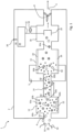
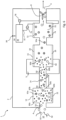
- a first example of particle sensor 1 has a body 2 defining an inlet 4 and an outlet 6.
- a fan 8 is configured to draw an air sample 10 along an air flow path in use, through a chamber which functions as a bipolar diffusion charger 12, a conduit 14, which extends from the bipolar diffusion charger to an ion trap 16, and then to a particle detection chamber 18 which comprises a Faraday cup 20, functioning as an electrometer.
- the invention is for analysing particles 50, 50a, 50b within an air sample 10 (the received particles).
- Particles are shown schematically and not to scale.
- neutrally charged particles 50 are shown with an open circle, a diagonally striped circle indicates a positively charged particle 50b and a circle with horizontal lines indicates a negatively charged particle 50c.
- ambient air includes some charged particles and/or free gas ions. Therefore some received particles may already be charged, with a charge distribution which depends on, inter alia, their source and age. However, the equilibrium processes of bipolar diffusion charging will mean that variations in the charge distribution in received particles will, unless highly charged, have negligible effect.
- the bipolar diffusion charger 12 includes an ionizing radiation source 22, which in an example is formed by three units of Americium-241 (alpha decay, 432.2 year half life), spaced apart along a flow chamber, and with a combined activity of under 111 kBq, and in another example is formed by Krypton-85 (beta decay, 10.76 years half life), 370MBq.
- ionizing radiation source 22 in an example is formed by three units of Americium-241 (alpha decay, 432.2 year half life), spaced apart along a flow chamber, and with a combined activity of under 111 kBq, and in another example is formed by Krypton-85 (beta decay, 10.76 years half life), 370MBq.
- the ion trap takes the form of a flow-through electrostatic precipitator which has opposed and oppositely charged electrodes 24, 26 and a circuit configured to maintain a potential difference between these electrodes in use.
- the electrometer comprises a current sensor 30, having an output 32 which is connected to an input of a controller 34 which in turn has a signal output 36 extending to an output interface 38.
- the controller typically comprises a processor (such as a microprocessor or microcontroller) executing stored code although its function may be implemented in whole or part with discrete electronic components.
- the air sample comprising uncharged particles 50 which are to be analysed, is drawn through the sensor by the action of the fan, into the bipolar diffusion charger 12.
- Ionizing radiation from the radiation source 22 ionises gas molecules to form a mixture of positively charged gas ions 60a and negatively charged gas ions 60b.
- these gas ions within the bipolar diffusion charger have a net zero charge.
- No electrical potential gradient is applied within the bipolar diffusion charger and the ions move by diffusion and by virtue of electrostatic forces (between charged particle and ions rather than by virtue of an externally applied electric field).
- the particles in the flowing gas (the received particles) sample collide with the positively and negatively charged ions and become charged so that there are concurrently formed both positively and negatively charged particles (50a, 50b).
- Bipolar diffusion charging uses a mixture of both positive and negative ions and the diffusion of these ions to charge particles, obtaining a mixture of positive and negative ions concurrently.
- the potential difference applied between the electrodes 24, 26 is selected to be sufficient to cause the free gas ions 60a, 60b which remain in the flowing gas sample to be drawn to the electrodes and therefore separated from the particles 50, 50a, 50b.
- the particles 50, 50a, 50b, without the gas ions continue to flow towards the detector 18.
- a Faraday cup electrometer 20 collects all of the particles, including the neutral particles, using a high-efficiency particulate air (HEPA) filter.
- HEPA particulate air
- the flux of charged particles into the electrometer induces an image current on the Faraday cup, which is measured by the ammeter 30.
- Air which is generally free of particles, passes out of the outlet 6.
- the controller 34 processes the measured current and the air speed to calculate a value of the first moment of the particle diameter distribution per unit volume, or a related property such as lung deposited surface area per unit volume, which it outputs as a digital or analogue signal throughout output 38.
- the speed of rotation of the fan 8 is sufficiently controlled, the speed of air flow may be known, and a constant scaling factor may be employed.
- an anemometer or other air flow sensor may be used to measure air flow velocity. In some embodiments, no fan is present, either because air is drawn or pushed through the filter at a known speed, or it is judged sufficient to measure the speed of air flow.
- the invention exploits several properties of the equilibrium charge distribution arising from bipolar diffusion charging.
- the fraction of total particles (f q ) at each charge state (q) as a function of diameter greater than 50 nm is estimated as follows by Gunn R. and Woessner R.
- ⁇ q d e 2 ⁇ G exp ⁇ q ⁇ Ge ⁇ 2 ln Z + / Z ⁇ 2 2 Ge ⁇ 2
- G 2 ⁇ 0 dkT for a given absolute temperature (T), positive to negative ion mobility ratio (Z + / Z - ), and the constants of electron charge (e), vacuum permittivity ( ⁇ 0 ) and Boltzmann's constant (k).
- Equation 5 Q is the volumetric flow rate of the gas containing the charged aerosol and N d is the number concentration of particles of diameter, d.
- Equation 5 The summation over the discrete charge states of Equation 4 requires a numerical calculation which can be analytically approximated as shown in Equation 5.
- Qe 2 ⁇ 0 kT e 2 ln Z + Z ⁇ d .
- Equation 5 states that the mean charge per particle ( q d ) and corresponding net current ( i d ) for a given particle diameter (d) is a simple linear function of the particle diameter (d), the gas temperature (T), and the natural log of the ratio of positive to negative ion mobilities (Z + /Z - ).
- d is the mean particle diameter of the polydispersed aerosol.
- q is the mean charge per particle over a polydisperse distribution whereas q d (of Eq. 5) is the mean charge per particle at one particle size.
- Nd the measured current, the gas flow rate and temperature, and the ratio of ion mobilities.
- the former can be measured accurately, while the latter can be determined for common mixtures.
- the net current detected at the Faraday cup electrometer will therefore be approximately proportional to Nd for a range of particle diameters and accordingly the current may be used to estimate the LDSA concentration of aerosols within the received sample.
- the particle sensor may therefore also be useful for measuring the net ratio of ion mobilities in a bipolar charger.
- the net ratio of ion mobilities in the bipolar charger can be calculated from the measured current, taking into account known or measured gas flow rate and known or measured temperature, using Equation 7.
- particles with a known size distribution and so known Nd are passed through a bipolar diffusion charger at a known or measured volumetric flow rate, at a known or measured temperature (and possibly humidity) and the measured current is processed to calculate the net ratio of ion mobilities within the bipolar diffusion charger.
- the resulting ratio is useful in a number of applications, for example it may be used to correct equilibrium charge states for use in the SMPS inversion algorithm for multiple-charge correction an SMPS devices.
- the ratio may be calculated to determine the effects of changes in gas composition on the ratio of ion mobilities.
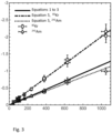
- Figure 3 demonstrates that in a practical embodiment, the mean charge per particle obtained using the radiation sources described above is a linear function of particle diameter, as predicted from theory, from about 50 nm to about 1000 nm. The relationships remain reasonably accurate below and above this range. Eventually, for sufficiently large particles, it is overtaken by other effects.
- Spherical particles (Bis(2-ethylhexyl) sebacate; DOS) were atomized using a nebulizer with HEPA-filtered, compressed air. A sample from the main flow of spherical particles was diluted using a disk diluter to provide a range of particle number concentrations (dilution ratios between 10 and 150), while the remaining aerosol was vented. A custom-built electrostatic precipitator (ESP) removed any particles charged during atomization or dilution. The diluted aerosol sample was then classified by an aerodynamic aerosol classifier to generate an aerodynamically monodispersed source. Since the DOS formed nano-droplets (i.e.
- the AAC classified particles were also monodispersed in particle geometric diameter which was calculated at each AAC setpoint. It should be noted that for spherical particles this geometric diameter is equivalent to the particle mobility diameter, a parameter commonly used by others to validate bipolar and unipolar diffusion charging theory ( Gopalakrishnan, R.; Thajudeen, T.; Ouyang, H.; Hogan Jr, C. J. The unipolar diffusion charging of arbitrary shaped aerosol particles. Journal of Aerosol Science 2013, 64, 60-80 ; and Gopalakrishnan, R.; McMurry, P. H.; Hogan Jr, C. J. The bipolar diffusion charging of nanoparticles: A review and development of approaches for non-spherical particles. Aerosol Science and Technology 2015, 49, 1181-1194 .)
- the neutral, monodispersed particles were sampled by a condensation particle counter (CPC) to measure particle number concentration (N) in parallel with the proof-of-concept measurement device.
- CPC condensation particle counter
- the disk diluter and AAC controlled the particle number concentration and size, respectively.
- the mean charge per particle can be determined based on the electrical current measured by the aerosol electrometer operating with flow rate (Q) and total particle number concentration (N) using Equation 5. This mean charge per particle (q) is compared against the one predicted by theory using Equation 5 with the total particle number concentration (N) measured by the CPC and the mean particle diameter selected by the AAC (d).
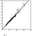
- Figure 4 shows the current obtained from the detector of a prototype device according to the present invention in comparison with a Naneos Partector reference instrument which is considerably more expensive than a sensor as described herein would cost (Naneos and Partector are trademarks of Naneos Particle Solutions GmbH, Windisch, Switzerland).
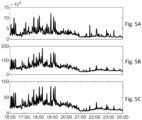
- Figures 5A, 5B and 5C show the output signal for measurements made near an urban road over time in Figure 5A , particle count information from a condensation particle counter (number concentration in units of particles per cubic centimetre), Figure 5B , the Naneos Partector (LDSA in units micrograms per cubic meter) and Figure 5C , a prototype device for the present embodiment (current in units of femtoAmps, which is proportional to LDSA).
- the detector according to the invention has an output which correlates closely with the reference device but in a simple product which can be manufactured at low cost.
- the output current is proportional to the first moment of particle size distribution and can therefore be used to estimate lung deposited surface area
- the reference device measures an output signal approximately proportional to the first moment of particle size distribution, subject to more environmental variables.
- the device can be substantially miniaturised, with the practical size of electronics likely to be the limiting size consideration.
- the radiation sources are comparable to or may be the same as those used in everyday smoke alarms and do not require special handling procedures for consumers. In contrast to, for example ionisers based on corona discharges, no ozone or other environmentally damaging gases are produced.
- the invention may use any bipolar ion source which produces an equilibrium charge distribution on particles.
- Embodiments for use in environments with high particle concentrations, or where high sample flow rates are required, may require ion sources which produce a greater excess of ions. Nevertheless, it is not essential that the bipolar charging of the particles actually reaches a steady state. Where insufficient ions are produced, or the particle residence time is too short (e.g. due to a high air speed), a steady state (equilibrium) might not be reached, but there will be a functional relationship between particle charge and mean diameter and concentration.
- An important feature of the invention is that the net charge on particles is relatively stable and, provided that an excess of ions is generated, is insensitive to variations in the rate of ion generation and the residence time of particles exposed to ions (in contrast to unipolar ion chargers, for example), provided they are above a minimum threshold. Accordingly, the embodiment described above with reference to Figure 1 does not require to include any means of measuring or controlling the rate of ion generation.
- the current which flows between the electrodes, 24, 26, could be measured and used as an indicator as to when a steady state is not being reached.
- the current generated from the capture of ions at either of the opposed electrodes would be lower than anticipated. This could be used to determine that the ion source is no longer functioning effectively.
- a decrease in the ion current over a relatively short period of time may indicate that there is an excessively high concentration of particles present. This could be useful to indicate that the device may not provide an accurate reading, or to provide a smoke detector function or an alarm for a high concentration of aerosols.
- the sensitivity of the device can be improved by employing modulation.
- the ion trap might be switched on and off according to a predetermined pattern, e.g. square wave, and the resulting modulation detected in the current measured at the electrometer. It would also be possible to modulate the ion source, for example with a shutter or gate between the radioactive element and the bulk of the volume of the bipolar diffusion chamber.
- particles which have been charged by bipolar diffusion charging are separated by polarity, i.e. the positive and negative particles are separated from each other. It is not critical whether the neutrally charged particles are, or are not, separated from other particles.
- Numbered features in Figure 6 correspond to correspondingly numbered features of Figure 1 .
- the bipolar diffusion charger 12 and ion trap 16 are as before.
- particle detection chamber 18 and Faraday cup electrometer 20 are replaced with a particle separation and detection chamber 70, which is downstream of the ion trap and which comprise a positively charged electrode 72 and an opposite negatively charged electrode 74.
- First and second ammeters 76 and 78 measure the current in each electrode in use.
- the potentials of the positively charged and negatively charged electrodes are selected to cause positively charged particles 50b to be captured by the negatively charged electrode 74, and their charge detected by the second ammeter, giving a current i+, while the negatively charged particles 50a are captured by the positively charged electrode 72 and their charge detected by the first ammeter, giving a current i - .
- Neutrally charged particles pass through the chamber and the outlet 6.
- the positively charged particle current, i+ comprises contributions from particles having each of a plurality of different positive charges
- the negatively charged particle current, i_ comprises contributions from particles having each of a plurality of different negative charges.
- the controller 34 processes i+ and i_ to determine size parameters of the particles, including the LDSA and/or first moment of the size distribution (Nd) of the particles, with reference to calculated or calibrated equivalence data representing the relationship between these currents, and number concentration and size parameters.
- the controller may calculate abs [i+] + abs [i - ] (abs referring to the absolute value of), referred to herein as the total aerosol current and/or abs [i+] - abs [i_], the net aerosol current, which corresponds to the current which would be measured using the first example sensor.
- Figure 7 shows the predicted magnitude of the mean charge per particle from different components of the aerosol sample assuming gas at standard conditions as a function of different particle diameters; specifically the magnitude of the mean charge per particle for positively charged particles, q + 82, the magnitude of the mean charge per particle for negatively charged particles, q _ 80, the sum of these, the total mean charge per particle, abs [ q + ] + abs [ q _], 84, and the magnitude of the difference between the positively charged particle and the negatively charged particles, the net mean charge per particle, abs [ q + ] - abs [ q _], 86.
- dashed lines are numerical solutions predicted by Gunn & Wiedensohler, and the dotted lines are an analytical solutions derived from Gunn to approximate the numeric solutions.
- This figure is an expansion of Figure 3 which only shows the net mean charge per particle.
- Figure 8 shows the predicted magnitude of the currents from different components of the aerosol sample assuming 10,000 particles per cubic centimetre of gas at standard conditions with a sample flow-rate of 0.3 L/min as a function of different particle diameters; specifically the positively charged particle current, i+, 82', the negatively charged particle current, _, 80', the sum of these, the total aerosol current, abs [i + ] + abs [i - ], 84' and the magnitude of the difference between the positively charged particle current and the negatively charged particle current, the net aerosol current, abs [i + ] - abs [i - ], 86'.
- Figure 7 shows the absolute mean charge per particle (abs[ q ])
- Figure 8 shows the corresponding aerosol current (i) assuming a particle concentration and sample flow-rate.
- the positively charged particle current, the negatively charged particle current, and the total aerosol current are each substantially larger than the net aerosol current, abs [i + ] - abs [i_], particularly at lower particle diameters.
- the ratio of total aerosol current to net aerosol current would be about 1900% for 2 nm diameter particles. This increase in measurable current may greatly improve measurement accuracy, particularly at low particle sizes where currents are smallest and prone to error.
- the controller 34 can independently calculate the number density of particles (N) and their mean diameter ( d ), rather than only the first moment of the particle size distribution.
- the independent currents may have different properties, for example the positively charged particle current, i+, is much less sensitive to particle size than the negatively charged particle current, i+.
- the positively charged particle current, i+ alone might give a useful indication of particle concentration within a range of uncertainty. This is relevant for example to periodic technical inspection requirements in Germany which allow a relatively high uncertainty for number concentration measurements.
- all positively charged particles are separated from all negatively charged particles.
- ions are formed in air molecules with properties and in a ratio which depends on the type and energy of radioactive decay as well as the state and composition of the carrier gas, which affects the net particle charge for a given diameter.
- the properties of the ions in the bipolar diffusion charger are manipulated. One way in which this can be achieved is to introduce new components to the received gas, either before the sample gas reaches the bipolar diffusion chamber, or within the bipolar diffusion charger. It is also possible to vary properties of the charger or the ion source. Changes in the difference between ion mobility for positive and negative charges affect the equilibrium charge distribution of the aerosol, and so one or more components of the gas or properties of the charger or ion source may be selected to increase the signal strength of the device.
- the bipolar diffusion charger comprises a salt such as NaCl or other easily ionisable chemicals (e.g. siloxanes from silicone), which would be preferentially ionised.
- a salt such as NaCl or other easily ionisable chemicals (e.g. siloxanes from silicone), which would be preferentially ionised.
- the presence of these chemicals changes the composition of the ions which are generated, especially the relative mobility of positive and negative ions, and therefore the charge distribution.
- a temperature regulator e.g. heater or cooler to control the temperature of the ions within the bipolar diffusion charger.
- the ion trap may in some embodiments not use an electrical potential gradient, but instead ions may be trapped at walls via Brownian diffusion or electrostatic forces.
- the ion trap may be an ion selective membrane. These embodiments provide a simpler device.
Landscapes
- Chemical & Material Sciences (AREA)
- Health & Medical Sciences (AREA)
- Life Sciences & Earth Sciences (AREA)
- Analytical Chemistry (AREA)
- General Health & Medical Sciences (AREA)
- Pathology (AREA)
- Immunology (AREA)
- Physics & Mathematics (AREA)
- General Physics & Mathematics (AREA)
- Biochemistry (AREA)
- Engineering & Computer Science (AREA)
- Dispersion Chemistry (AREA)
- Combustion & Propulsion (AREA)
- Medicinal Chemistry (AREA)
- Food Science & Technology (AREA)
- Biomedical Technology (AREA)
- Molecular Biology (AREA)
- Other Investigation Or Analysis Of Materials By Electrical Means (AREA)
Claims (15)
- Partikelsensor (1), umfassend einen Einlass (4) zum Aufnehmen einer Gasprobe für eine Analyse, einen bipolaren Diffusionslader (12), der konfiguriert ist, um aufgenommene Partikel innerhalb der aufgenommenen Gasprobe durch die Kollision der aufgenommenen Partikel mit und eine gleichzeitige Übertragung einer Ladung von sowohl positiven als auch negativen Ionen zu laden, und mindestens ein Elektrometer (20), das konfiguriert ist, um die Ladung von dadurch geladenen aufgenommenen Partikel zu detektieren, wobei der Partikelsensor eine lonenfalle (16) zwischen dem bipolaren Diffusionslader und mindestens einem Elektrometer umfasst, wobei die lonenfalle konfiguriert ist, um freie positive und negative Ionen von der Mischung aus aufgenommenen Partikeln und positiven und negativen Ionen, die in dem bipolaren Diffusionslader ausgebildet werden, zu entfernen, bevor die aufgenommenen Partikel mindestens ein Elektrometer erreichen.
- Partikelsensor nach Anspruch 1, wobei die lonenfalle ein Paar voneinander beabstandeter Elektroden (24, 26) umfasst, die in Verwendung entgegengesetzt geladen werden, wobei optional der Strom, der von dem Einfangen von Ionen an einer der voneinander beabstandeten Elektroden erzeugt wird, nicht verwendet wird, um eine Ausgabe des Sensors zu bestimmen, wobei als eine weitere Option der Strom, der von dem Einfangen von Ionen an einer der voneinander beabstandeten Elektroden erzeugt wird, gemessen wird und die Steuerung den Strom verarbeitet, um einen oder mehrere Parameter des Ladungsflusses in dem bipolaren Diffusionslader zu bestimmen, oder um einen Überschuss an Partikeln zu detektieren, beispielsweise, um in dem Fall eines Feuers Rauch zu detektieren.
- Partikelsensor nach einem der Ansprüche 1 oder 2, wobei die lonenfalle ein Elektrometer umfasst und es mindestens ein weiteres Elektrometer nachgeschaltet der lonenfalle gibt.
- Partikelsensor nach Anspruch 1, wobei die lonenfalle konfiguriert ist, um die Ionen durch Diffusion von den aufgenommenen Partikeln zu trennen.
- Partikelsensor nach einem der vorstehenden Ansprüche, wobei es eine Leitung (14) zwischen dem bipolaren Diffusionslader und der lonenfalle gibt, und/oder wobei der Partikelsensor ferner eine Schaltung umfasst, die konfiguriert ist, um Signale von dem mindestens einen Elektrometer (20) aufzunehmen und mindestens einen Parameter der Konzentration und/oder Größe der aufgenommenen Partikel in der aufgenommenen Gasprobe zu berechnen,und/oder wobei der bipolare Diffusionslader ein radioaktives Material umfasst,und/oder wobei ein Laden der Partikel einen Steadystate erreicht.
- Partikelsensor nach einem der vorstehenden Ansprüche, wobei mindestens einige der aufgenommenen dadurch geladenen Partikel, der gleichen Polarität, von Partikeln unterschiedlicher und/oder entgegengesetzter Polarität getrennt werden, vor oder zu der gleichen Zeit wie der Messschritt durch das mindestens eine Elektrometer (20), oder wobei die aufgenommenen Partikel vor dem Messschritt durch das mindestens eine Elektrometer nach Ladungspolarität getrennt werden, wobei optional sowohl Messungen der Summe der Ladung der getrennten positiv geladenen Partikel als auch der Summe der Ladung der getrennten negativ geladenen Partikel erhalten werden, und/oder wobei ein oder mehrere Elektrometer konfiguriert sind, um sowohl mindestens einige der aufgenommenen Partikel, der gleichen Polarität, zu trennen als auch um die Ladung der getrennten Partikel zu messen.
- Partikelsensor nach Anspruch 6, wobei die Partikel durch einen Potentialgradienten zwischen Elektroden getrennt werden, wobei der Potentialunterschied zwischen den Elektroden derart gewählt ist, dass die getrennten Partikel eine positive Ladung, und eine elektrische Mobilität höher als ein Schwellenwert, oder eine negative Ladung, und eine elektrische Mobilität höher als ein Schwellenwert, aufweisen, und wobei das mindestens eine Elektrometer die getrennten Partikel misst.
- Partikelsensor nach einem der Ansprüche 1 bis 5, wobei die aufgenommenen Partikel durch das mindestens eine Elektrometer gemessen werden, ohne dass positiv und negativ geladene aufgenommene Partikel voneinander getrennt werden.
- Partikelsensor nach einem der vorstehenden Ansprüche, wobei der Partikelsensor einen Luftstromregler (8) oder einen Luftstromgeschwindigkeitssensor umfasst, und/oder wobei ein oder mehrere Elektrometer als Ladungssummierungsdetektoren fungieren, beispielsweise wobei ein oder mehrere Elektrometer einen Faraday-Becher oder ein Drahtgitter umfassen, und/oder wobei die aufgenommenen Partikel ein Aerosol sind, und/oder wobei der bipolare Diffusionslader ein ionisierbares Material umfasst, das während eines Betriebs innerhalb des bipolaren Diffusionsladers ionisiert wird.
- Verfahren zum Messen eines Parameters der Konzentration und/oder Größe von Partikeln in einer Gasprobe für die Analyse, das Verfahren umfassend die Schritte des Aufnehmens einer Gasprobe, umfassend Partikel, des Ladens der aufgenommenen Partikel in der Gasprobe durch bipolares Diffusionsladen, wobei dadurch die aufgenommenen Partikel durch die Kollision von Partikeln mit und die gleichzeitige Übertragung der Ladung von sowohl positiven als auch negativen Ionen geladen werden, und ein Verwenden mindestens eines Elektrometers, um die Ladung von aufgenommenen Partikel, die dadurch geladen werden, zu detektieren, wobei das Verfahren ein Trennen freier positiver und negativer Ionen von der Mischung von aufgenommenen Partikeln und positiven und negativen Ionen, die während des bipolaren Diffusionsladens ausgebildet werden, umfasst, wobei die positiven und negativen Ionen durch eine lonenfalle entfernt werden, bevor die aufgenommenen Partikel mindestens ein Elektrometer erreichen.
- Verfahren nach Anspruch 10, wobei als ein Ergebnis des bipolaren Diffusionsladens die aufgenommenen Partikel eine negative Nettoladung oder eine positive Nettoladung aufweisen und die Nettoladung durch das mindestens eine Elektrometer gemessen wird.
- Verfahren nach Anspruch 10 oder 11, wobei Parameter des Ladungsflusses von Ionen innerhalb des bipolaren Diffusionsladers nicht gemessen werden, und/oder wobei die aufgenommenen Partikel durch einen elektrischen Potentialgradienten, der zwischen Elektroden angelegt ist, von den positiven und negativen Ionen getrennt werden und der Strom zwischen den Elektroden nicht überwacht wird, und/oder umfassend das Trennen einiger oder aller der positiv oder negativ geladenen aufgenommenen Partikel, die durch den bipolaren Diffusionslader geladen wurden, von Partikeln unterschiedlicher und/oder entgegengesetzter Polarität, und das Messen der Ladung der getrennten positiv und/oder negativ geladenen aufgenommenen Partikel, und/oder wobei die aufgenommenen Partikel durch einen Potentialunterschied, der zwischen zwei Elektroden angelegt ist, getrennt werden und der Strom an jeder Elektrode gemessen wird, wobei dadurch ein Signal, das eine Messung der Ladungen der positiv geladenen Partikel ist, und ein Signal, das eine Messung der Ladungen der negativ geladenen Partikel ist, bereitgestellt wird, und/oder wobei die aufgenommenen Partikel durch einen elektrischen Potentialgradienten, der zwischen Elektroden angelegt ist, von den positiven und negativen Ionen getrennt werden und der Strom zwischen den Elektroden überwacht wird, um die lonisationsrate zu messen oder um das Vorhandensein einer Konzentration von Partikeln zu detektieren, die einen Schwellenwert überschreitet, oder um Rauch zu detektieren, und/oder wobei die positiven und negativen Ionen durch Kollisionen zwischen Molekülen und Strahlung von einem radioaktiven Material erzeugt werden.
- Verfahren nach Anspruch 12, wobei die positiven und negativen Ionen durch Kollisionen zwischen einem ionenerzeugenden Gas oder einem festen oder flüssigen stationären Opfermaterial und einem radioaktiven Material erzeugt werden.
- Verfahren nach einem der Ansprüche 10 bis 13, wobei das Laden der Partikel durch die positiven und negativen Ionen keinen Steadystate erreicht, und/oder wobei die Laderate von Gasmolekülen durch die lonenquelle, oder die Absorption von Ionen durch die lonenfalle, moduliert wird und die Messung von einem oder mehreren Elektrometern demoduliert wird.
- Verfahren nach einem der Ansprüche 10 bis 14, wobei mindestens ein Elektrometer die Nettoladung nicht getrennter positiver und negativer geladener Partikel misst, oder wobei das Verfahren das Trennen mindestens einiger der positiv oder negativ geladenen Partikel von Partikeln unterschiedlicher und/oder entgegengesetzter Polarität umfasst und das mindestens eine Elektrometer die Nettoladung der getrennten geladenen Partikel misst, optional sowohl die Nettoladung getrennter positiv geladener Partikel als auch die Nettoladung getrennter negativ geladener Partikel.
Applications Claiming Priority (3)
| Application Number | Priority Date | Filing Date | Title |
|---|---|---|---|
| GBGB1911091.5A GB201911091D0 (en) | 2019-08-02 | 2019-08-02 | Particle sensor and sensing method |
| GBGB1919455.4A GB201919455D0 (en) | 2019-12-31 | 2019-12-31 | Particle sensor and sensing method |
| PCT/GB2020/051820 WO2021023972A1 (en) | 2019-08-02 | 2020-07-30 | Particle sensor and sensing method |
Publications (3)
| Publication Number | Publication Date |
|---|---|
| EP4007904A1 EP4007904A1 (de) | 2022-06-08 |
| EP4007904C0 EP4007904C0 (de) | 2024-08-21 |
| EP4007904B1 true EP4007904B1 (de) | 2024-08-21 |
Family
ID=71948619
Family Applications (1)
| Application Number | Title | Priority Date | Filing Date |
|---|---|---|---|
| EP20751261.7A Active EP4007904B1 (de) | 2019-08-02 | 2020-07-30 | Partikelsensor und messverfahren |
Country Status (4)
| Country | Link |
|---|---|
| US (1) | US12298216B2 (de) |
| EP (1) | EP4007904B1 (de) |
| CA (1) | CA3149617A1 (de) |
| WO (1) | WO2021023972A1 (de) |
Family Cites Families (83)
| Publication number | Priority date | Publication date | Assignee | Title |
|---|---|---|---|---|
| US3573460A (en) | 1966-09-12 | 1971-04-06 | Gen Electric | Ion chamber detector for submicron particles |
| US3735138A (en) | 1971-10-27 | 1973-05-22 | Honeywell Inc | Ionization smoke detector |
| US4053776A (en) | 1976-05-25 | 1977-10-11 | The United States Of America As Represented By Thesecretary Of The Interior | Sub-micron particle detector |
| US4435681A (en) * | 1981-09-28 | 1984-03-06 | Senichi Masuda | Bipolar ionic current probe unit and method for measuring positive and negative current densities by means of the same probe unit |
| DE3417525C1 (de) | 1984-05-11 | 1986-01-09 | Matter + Siegmann Ag, Wohlen | Vorrichtung zur quantitativen und qualitativen Erfassung von kohlenwasserstoffhaltigen Schwebeteilchen in Gasen |
| US4790650A (en) | 1987-04-17 | 1988-12-13 | Tsi Incorporated | Condensation nucleus counter |
| DE3907387A1 (de) | 1989-03-08 | 1990-09-13 | Singer Hermann | Verfahren zur messung von partikeln in polydispersen systemen und von partikelkonzentrationen monodisperser aerosole sowie messvorrichtung zur durchfuehrung des verfahrens |
| DE4038994C2 (de) | 1990-12-06 | 1994-03-10 | Lehmann Martin | Verfahren zum Ermitteln einer Meßgröße und Meßanordnung |
| US5118959A (en) | 1991-05-03 | 1992-06-02 | Tsi Incorporated | Water separation system for condensation particle counter |
| DE4305704B4 (de) | 1993-02-25 | 2006-02-16 | Matter + Siegmann Ag | Verfahren und Vorrichtung zur Untersuchung von in einem Gas befindlichen Partikeln |
| US5498271A (en) | 1994-10-07 | 1996-03-12 | Msp Corporation | Diesel particle virtual impactor sampler |
| US6003389A (en) | 1996-09-05 | 1999-12-21 | California Institute Of Technology | Enhanced automated classified aerosol detector |
| US6230572B1 (en) | 1998-02-13 | 2001-05-15 | Tsi Incorporated | Instrument for measuring and classifying nanometer aerosols |
| GB2346700B (en) | 1999-01-12 | 2001-02-14 | Cambustion Ltd | Ultra-fast,sub-micrometer particulate size detector |
| WO2000078447A1 (en) | 1999-06-18 | 2000-12-28 | Tsi Incorporated | Aerosol charge adjusting apparatus employing a corona discharge |
| ATE393387T1 (de) | 2000-05-19 | 2008-05-15 | Matter Engineering Ag | Verfahren zum dynamischen nachweis der anzahldichte und grösse von nanometrischen partikeln in gasen |
| FI20001685A0 (fi) | 2000-07-19 | 2000-07-19 | Tr Tech Int Oy | Mittausjärjestelmä ja menetelmä hiukkasnopeuden ja/tai hiukkasnopeusjakauman ja/tai hiukkaskoon ja/tai hiukkaskokojakauman mittaamiseksi |
| US6781119B2 (en) * | 2000-12-14 | 2004-08-24 | Mks Instruments, Inc. | Ion storage system |
| GB2374671B (en) | 2001-04-18 | 2003-06-04 | Cambustion Ltd | Methods to improve electrostatic particle measurement |
| GB2378510B (en) | 2001-08-04 | 2003-10-08 | Cambustion Ltd | Improvement of electrical particle size classification |
| US6639671B1 (en) | 2002-03-01 | 2003-10-28 | Msp Corporation | Wide-range particle counter |
| DE10229411A1 (de) | 2002-06-29 | 2004-01-29 | Robert Bosch Gmbh | Verfahren zum Bestimmen des Teilchenanteils in einem Gasstrom |
| JP4197522B2 (ja) | 2003-07-10 | 2008-12-17 | ヤマハ発動機株式会社 | エンジン |
| GB2416913A (en) | 2004-08-07 | 2006-02-08 | Cambustion Ltd | A centrifugal particle mass analyser |
| EP1655595B1 (de) * | 2004-11-03 | 2009-10-07 | GRIMM Aerosol Technik GmbH & Co.KG | Verfahren und Vorrichtung zur Messung der Anzahlkonzentration und des mittleren Durchmessers von in einem Trägergas suspendierten Partikeln |
| EP1681550A1 (de) | 2005-01-13 | 2006-07-19 | Matter Engineering AG | Verfahren und Vorrichtung zur Messung von Anzahlkonzentration und mittlerem Durchmesser von Aerosolpartikeln |
| JP2008542721A (ja) | 2005-05-23 | 2008-11-27 | ティエスアイ インコーポレイテッド | ナノ粒子接触測定装置 |
| JP2008544294A (ja) | 2005-06-28 | 2008-12-04 | コーニンクレッカ フィリップス エレクトロニクス エヌ ヴィ | 超微細粒子センサ |
| US8301396B1 (en) | 2006-10-20 | 2012-10-30 | Clarkson University | Miniature ultrafine particle sensor |
| EP1965192A1 (de) | 2007-03-02 | 2008-09-03 | Technische Universiteit Delft | Verfahren und Vorrichtung zur Messung des elementaren Kohlenstoffgehalts in einem Aerosol aus Rußpartikeln |
| WO2009074910A1 (en) | 2007-12-12 | 2009-06-18 | Koninklijke Philips Electronics N.V. | Device for characterizing a size distribution of electrically-charged airborne particles in an air flow |
| DE102008015256A1 (de) | 2008-03-20 | 2009-10-01 | Continental Automotive Gmbh | Diagnoseverfahren und Diagnosesystem für einen Partikelfilter eines Verbrennungsmotors, insbesondere für einen Rußfilter in einem Dieselkraftfahrzeug |
| JP5906087B2 (ja) * | 2008-11-25 | 2016-04-20 | コーニンクレッカ フィリップス エヌ ヴェKoninklijke Philips N.V. | 浮遊粒子を感知するセンサ |
| WO2010136633A1 (en) * | 2009-05-26 | 2010-12-02 | Tampereen Teknillinen Yliopisto | Method and apparatus for generating test aerosol |
| DE102009028239A1 (de) | 2009-08-05 | 2011-02-10 | Robert Bosch Gmbh | Verfahren und Vorrichtung zur Eigendiagnose eines Partikelsensors |
| DE102009046315A1 (de) | 2009-11-03 | 2011-05-05 | Robert Bosch Gmbh | Verfahren und Vorrichtung zum Betreiben eines Partikelsensors |
| DE102009046749A1 (de) | 2009-11-17 | 2011-05-19 | Robert Bosch Gmbh | Vorrichtung zum Betrieb eines Partikelsensors |
| FIU20100090U0 (fi) | 2010-02-25 | 2010-02-25 | Pegasor Oy | Pakokaasuanturi |
| US9764333B2 (en) | 2010-03-10 | 2017-09-19 | Msp Corporation | Electrical ionizer for aerosol charge conditioning and measurement |
| DE102010019076B4 (de) | 2010-04-30 | 2018-02-01 | Continental Automotive Gmbh | Optischer Rußpartikelsensor |
| DE102010030634A1 (de) | 2010-06-29 | 2011-12-29 | Robert Bosch Gmbh | Verfahren und Vorrichtung zum Betreiben eines Partikelsensors |
| FIU20100360U0 (fi) | 2010-08-20 | 2010-08-20 | Kauko Janka | Sähköinen hiukkasmittauslaite |
| US9140653B2 (en) | 2010-10-08 | 2015-09-22 | Tsi Incorporated | Spark emission particle detector |
| DE102010064299B4 (de) | 2010-12-29 | 2021-02-04 | Robert Bosch Gmbh | Sensor und Verfahren zum Betreiben eines Sensors |
| FI20106395A0 (fi) | 2010-12-31 | 2010-12-31 | Pegasor Oy | Laitteisto |
| FI20115045A0 (fi) | 2011-01-18 | 2011-01-18 | Pegasor Oy | Laite ja menetelmä hiukkasten tarkkailemiseksi |
| JP5213979B2 (ja) * | 2011-03-17 | 2013-06-19 | 日本特殊陶業株式会社 | 微粒子センサおよびその取付構造 |
| FI20115272A0 (fi) | 2011-03-21 | 2011-03-21 | Pegasor Oy | Laitteisto hiukkasten tarkkailemiseksi |
| JP5537487B2 (ja) | 2011-04-12 | 2014-07-02 | 日本特殊陶業株式会社 | 微粒子検知システム |
| WO2012142297A1 (en) | 2011-04-13 | 2012-10-18 | Tsi, Incorporated | Apparatus and method for improving particle count accuracy in low pressure applications |
| EP2741843B1 (de) | 2011-08-09 | 2020-02-12 | TSI, Incorporated | System und verfahren zur umwandlung optischer durchmesser von aerosolpartikeln in mobilitäts- und aerodynamische durchmesser |
| EP2758767B1 (de) | 2011-09-20 | 2017-11-08 | TSI, Incorporated | Systeme zur charakterisierung eines aerosolpartikelstroms |
| CN203443878U (zh) | 2011-12-08 | 2014-02-19 | 皮卡索尔公司 | 用于监测包括气溶胶的通道或空间内的颗粒的装置 |
| FI126815B (en) | 2011-12-08 | 2017-06-15 | Pegasor Oy | EQUIPMENT FOR PARTICULATE MONITORING |
| US8611066B2 (en) | 2011-12-09 | 2013-12-17 | Centers For Disease Control And Prevention | Non-radioactive bipolar charger for aerosol particles |
| WO2013109942A1 (en) | 2012-01-20 | 2013-07-25 | Tsi, Incorporated | Instrument for sizing nanoparticles and a component therefor |
| WO2013121095A1 (en) | 2012-02-18 | 2013-08-22 | Pegasor Oy | Apparatus and process for producing acknowledged air flow and the use of such apparatus in measuring particle concentration in acknowledged air flow |
| EP2815473A1 (de) | 2012-02-18 | 2014-12-24 | Pegasor OY | Vorrichtung und verfahren zur herstellung eines bestätigten luftstroms und verwendung einer solchen vorrichtung zur messung einer partikelkonzentration in einem bestätigten luftstrom |
| WO2013121115A1 (en) | 2012-02-19 | 2013-08-22 | Pegasor Oy | Apparatus and method for flushing particle measurement device |
| FI20125189L (fi) | 2012-02-19 | 2013-08-20 | Pegasor Oy | Laite ja menetelmä hiukkasten mittaamiseksi |
| JP5774516B2 (ja) | 2012-02-21 | 2015-09-09 | 日本特殊陶業株式会社 | 微粒子センサ |
| CN104487817B (zh) | 2012-03-06 | 2017-11-03 | 皮卡索尔公司 | 用于颗粒质量浓度测量的设备和过程以及对用于颗粒质量浓度测量的设备的使用 |
| JP5829556B2 (ja) | 2012-03-15 | 2015-12-09 | 日本特殊陶業株式会社 | 微粒子検知システム |
| KR101338083B1 (ko) | 2012-06-29 | 2013-12-06 | 현대자동차주식회사 | 디젤엔진의 수트측정센서 |
| CH706903A2 (de) | 2012-08-30 | 2014-03-14 | Naneos Particle Solutions Gmbh | Verfahren zur Messung von Aerosolen durch induzierte Ströme als Folge einer gepulsten Aufladung. |
| US9541488B2 (en) | 2012-09-21 | 2017-01-10 | Msp Corporation | Particle sampling and measurement in the ambient air |
| JP6053603B2 (ja) | 2013-05-02 | 2016-12-27 | 日本特殊陶業株式会社 | 微粒子測定システム |
| US20140340093A1 (en) | 2013-05-18 | 2014-11-20 | Brechtel Manufacturing, Inc. | Liquid ion detector |
| DE102013209872A1 (de) | 2013-05-28 | 2014-12-04 | Robert Bosch Gmbh | Verfahren und Vorrichtung zum Betreiben eines Partikelsensors |
| GB201310355D0 (en) | 2013-06-11 | 2013-07-24 | Particle Measuring System Inc | Apparatus for charging or adjusting the charge of aerosol apparatus |
| KR101528773B1 (ko) | 2014-05-16 | 2015-06-15 | 연세대학교 산학협력단 | 대기중의 바이오 입자 및 넌바이오 입자 실시간 검출장치 및 이를 이용한 검출방법 |
| US10006846B2 (en) | 2014-06-10 | 2018-06-26 | Koninklijke Philips N.V. | Aerosol sensor and sensing method |
| JP2017517729A (ja) | 2014-06-10 | 2017-06-29 | コーニンクレッカ フィリップス エヌ ヴェKoninklijke Philips N.V. | エアロゾル質量センサ及びセンサ方法 |
| WO2016002647A1 (ja) | 2014-07-04 | 2016-01-07 | 株式会社島津製作所 | 粒子荷電装置及び該装置を用いた粒子分級装置 |
| US9726579B2 (en) | 2014-12-02 | 2017-08-08 | Tsi, Incorporated | System and method of conducting particle monitoring using low cost particle sensors |
| WO2016193246A1 (en) | 2015-06-05 | 2016-12-08 | Koninklijke Philips N.V. | Particle sensor and sensing method |
| JP6454237B2 (ja) | 2015-07-07 | 2019-01-16 | 日本特殊陶業株式会社 | 微粒子センサ |
| FR3039434B1 (fr) | 2015-07-28 | 2018-02-16 | Commissariat A L'energie Atomique Et Aux Energies Alternatives | Dispositif de collecte de particules contenues dans un aerosol, muni d'electrometres pour determiner la concentration et la granulometrie des nanoparticules |
| FR3039435B1 (fr) | 2015-07-28 | 2017-08-18 | Commissariat Energie Atomique | Methode et dispositif de collecte de particules d'aerosols, a collecte selective en fonction de la granulometrie des particules |
| JP6335861B2 (ja) | 2015-10-27 | 2018-05-30 | 日本特殊陶業株式会社 | 微粒子測定システム |
| GB201609868D0 (en) * | 2016-06-06 | 2016-07-20 | Cambridge Entpr Ltd | Particle measurement apparatus |
| WO2018058236A1 (en) | 2016-09-29 | 2018-04-05 | Clad Innovations Ltd. | Highly integrated optical particle counter (opc) |
| EP3652519B1 (de) * | 2017-07-14 | 2024-09-04 | Pegasor Oy | Verfahren zur überwachung von partikeln |
-
2020
- 2020-07-30 EP EP20751261.7A patent/EP4007904B1/de active Active
- 2020-07-30 WO PCT/GB2020/051820 patent/WO2021023972A1/en not_active Ceased
- 2020-07-30 US US17/632,013 patent/US12298216B2/en active Active
- 2020-07-30 CA CA3149617A patent/CA3149617A1/en active Pending
Also Published As
| Publication number | Publication date |
|---|---|
| EP4007904C0 (de) | 2024-08-21 |
| US20220268684A1 (en) | 2022-08-25 |
| CA3149617A1 (en) | 2021-02-11 |
| WO2021023972A1 (en) | 2021-02-11 |
| EP4007904A1 (de) | 2022-06-08 |
| US12298216B2 (en) | 2025-05-13 |
Similar Documents
| Publication | Publication Date | Title |
|---|---|---|
| EP2370802B1 (de) | Sensor zur wahrnehmung in der luft befindlicher partikel | |
| US8181505B2 (en) | Measurement system for the multidimensional aerosol characterization | |
| KR101540914B1 (ko) | 공기 흐름 내에서 전기적으로 충전된 공기중 입자들의 크기 분포를 특성화하기 위한 디바이스 | |
| JP5480157B2 (ja) | 気流における帯電浮遊粒子のサイズ分布を特徴付けるデバイス | |
| EP2815226B1 (de) | Vorrichtung und verfahren zur herstellung eines luftstroms und verwendung einer solchen vorrichtung bei der messung von partikelkonzentrationen in einem luftstrom | |
| Ku et al. | Comparison of diffusion charging and mobility-based methods for measurement of aerosol agglomerate surface area | |
| Asbach et al. | On the effect of wearing personal nanoparticle monitors on the comparability of personal exposure measurements | |
| Nishida et al. | Modelling the effect of aerosol polydispersity on unipolar charging and measurement in low-cost sensors | |
| EP4007904B1 (de) | Partikelsensor und messverfahren | |
| KR101854986B1 (ko) | 나노입자 분석방법 및 이의 시스템 | |
| JP4710787B2 (ja) | 粒子分級装置 | |
| Hyun et al. | Design and performance evaluation of a PN1 sensor for real-time measurement of indoor aerosol size distribution | |
| Nishida et al. | On the three charge regimes of bipolar charge conditioners | |
| Park et al. | Development and performance test of a micromachined unipolar charger for measurements of submicron aerosol particles having a log-normal size distribution | |
| Laakkonen et al. | Effect of operation pressure on the response of ePNC particle number concentration sensor | |
| Ranjan et al. | A new miniature electrical aerosol spectrometer (MEAS): Experimental characterization | |
| Intra et al. | Use of electrostatic precipitation for excess ion trapping in an electrical aerosol detector | |
| Tardos et al. | Electrical charge measurements on fine airborne particles | |
| Cong et al. | Design of On-Line Measurement System for Fine Particle Number Concentration of Vehicle Exhaust Based on Diffusion Charge Theory | |
| Schmidt‐Ott | New developments in aerosol characterization from the physical point of view | |
| VUORINEN | CHARGE CARRIER AGGLOMERATES IN AN ELECTROSTATIC SOOT SENSOR | |
| He et al. | Aerosol Analysis via Electrostatic Precipitation-Electrospray Ionization Mass Spectrometry (EP-ESI-MS) | |
| Chen et al. | Aerosol Instrumentation | |
| HK1151096B (en) | Measurement system for the multidimensional aerosol characterization |
Legal Events
| Date | Code | Title | Description |
|---|---|---|---|
| STAA | Information on the status of an ep patent application or granted ep patent |
Free format text: STATUS: UNKNOWN |
|
| STAA | Information on the status of an ep patent application or granted ep patent |
Free format text: STATUS: THE INTERNATIONAL PUBLICATION HAS BEEN MADE |
|
| PUAI | Public reference made under article 153(3) epc to a published international application that has entered the european phase |
Free format text: ORIGINAL CODE: 0009012 |
|
| STAA | Information on the status of an ep patent application or granted ep patent |
Free format text: STATUS: REQUEST FOR EXAMINATION WAS MADE |
|
| 17P | Request for examination filed |
Effective date: 20220202 |
|
| AK | Designated contracting states |
Kind code of ref document: A1 Designated state(s): AL AT BE BG CH CY CZ DE DK EE ES FI FR GB GR HR HU IE IS IT LI LT LU LV MC MK MT NL NO PL PT RO RS SE SI SK SM TR |
|
| DAV | Request for validation of the european patent (deleted) | ||
| DAX | Request for extension of the european patent (deleted) | ||
| GRAP | Despatch of communication of intention to grant a patent |
Free format text: ORIGINAL CODE: EPIDOSNIGR1 |
|
| STAA | Information on the status of an ep patent application or granted ep patent |
Free format text: STATUS: GRANT OF PATENT IS INTENDED |
|
| INTG | Intention to grant announced |
Effective date: 20240319 |
|
| GRAS | Grant fee paid |
Free format text: ORIGINAL CODE: EPIDOSNIGR3 |
|
| GRAA | (expected) grant |
Free format text: ORIGINAL CODE: 0009210 |
|
| STAA | Information on the status of an ep patent application or granted ep patent |
Free format text: STATUS: THE PATENT HAS BEEN GRANTED |
|
| RIN1 | Information on inventor provided before grant (corrected) |
Inventor name: BOIES, ADAM MEYER Inventor name: HOCHGREB, SIMONE Inventor name: JOHNSON, TYLER JAMES Inventor name: NISHIDA, ROBERT |
|
| AK | Designated contracting states |
Kind code of ref document: B1 Designated state(s): AL AT BE BG CH CY CZ DE DK EE ES FI FR GB GR HR HU IE IS IT LI LT LU LV MC MK MT NL NO PL PT RO RS SE SI SK SM TR |
|
| REG | Reference to a national code |
Ref country code: GB Ref legal event code: FG4D |
|
| REG | Reference to a national code |
Ref country code: CH Ref legal event code: EP |
|
| REG | Reference to a national code |
Ref country code: IE Ref legal event code: FG4D |
|
| REG | Reference to a national code |
Ref country code: DE Ref legal event code: R096 Ref document number: 602020036243 Country of ref document: DE |
|
| U01 | Request for unitary effect filed |
Effective date: 20240920 |
|
| U07 | Unitary effect registered |
Designated state(s): AT BE BG DE DK EE FI FR IT LT LU LV MT NL PT RO SE SI Effective date: 20241011 |
|
| PG25 | Lapsed in a contracting state [announced via postgrant information from national office to epo] |
Ref country code: NO Free format text: LAPSE BECAUSE OF FAILURE TO SUBMIT A TRANSLATION OF THE DESCRIPTION OR TO PAY THE FEE WITHIN THE PRESCRIBED TIME-LIMIT Effective date: 20241121 |
|
| PG25 | Lapsed in a contracting state [announced via postgrant information from national office to epo] |
Ref country code: GR Free format text: LAPSE BECAUSE OF FAILURE TO SUBMIT A TRANSLATION OF THE DESCRIPTION OR TO PAY THE FEE WITHIN THE PRESCRIBED TIME-LIMIT Effective date: 20241122 Ref country code: PL Free format text: LAPSE BECAUSE OF FAILURE TO SUBMIT A TRANSLATION OF THE DESCRIPTION OR TO PAY THE FEE WITHIN THE PRESCRIBED TIME-LIMIT Effective date: 20240821 |
|
| PG25 | Lapsed in a contracting state [announced via postgrant information from national office to epo] |
Ref country code: IS Free format text: LAPSE BECAUSE OF FAILURE TO SUBMIT A TRANSLATION OF THE DESCRIPTION OR TO PAY THE FEE WITHIN THE PRESCRIBED TIME-LIMIT Effective date: 20241221 |
|
| PG25 | Lapsed in a contracting state [announced via postgrant information from national office to epo] |
Ref country code: HR Free format text: LAPSE BECAUSE OF FAILURE TO SUBMIT A TRANSLATION OF THE DESCRIPTION OR TO PAY THE FEE WITHIN THE PRESCRIBED TIME-LIMIT Effective date: 20240821 |
|
| PG25 | Lapsed in a contracting state [announced via postgrant information from national office to epo] |
Ref country code: ES Free format text: LAPSE BECAUSE OF FAILURE TO SUBMIT A TRANSLATION OF THE DESCRIPTION OR TO PAY THE FEE WITHIN THE PRESCRIBED TIME-LIMIT Effective date: 20240821 Ref country code: RS Free format text: LAPSE BECAUSE OF FAILURE TO SUBMIT A TRANSLATION OF THE DESCRIPTION OR TO PAY THE FEE WITHIN THE PRESCRIBED TIME-LIMIT Effective date: 20241121 |
|
| PG25 | Lapsed in a contracting state [announced via postgrant information from national office to epo] |
Ref country code: RS Free format text: LAPSE BECAUSE OF FAILURE TO SUBMIT A TRANSLATION OF THE DESCRIPTION OR TO PAY THE FEE WITHIN THE PRESCRIBED TIME-LIMIT Effective date: 20241121 Ref country code: PL Free format text: LAPSE BECAUSE OF FAILURE TO SUBMIT A TRANSLATION OF THE DESCRIPTION OR TO PAY THE FEE WITHIN THE PRESCRIBED TIME-LIMIT Effective date: 20240821 Ref country code: NO Free format text: LAPSE BECAUSE OF FAILURE TO SUBMIT A TRANSLATION OF THE DESCRIPTION OR TO PAY THE FEE WITHIN THE PRESCRIBED TIME-LIMIT Effective date: 20241121 Ref country code: IS Free format text: LAPSE BECAUSE OF FAILURE TO SUBMIT A TRANSLATION OF THE DESCRIPTION OR TO PAY THE FEE WITHIN THE PRESCRIBED TIME-LIMIT Effective date: 20241221 Ref country code: HR Free format text: LAPSE BECAUSE OF FAILURE TO SUBMIT A TRANSLATION OF THE DESCRIPTION OR TO PAY THE FEE WITHIN THE PRESCRIBED TIME-LIMIT Effective date: 20240821 Ref country code: GR Free format text: LAPSE BECAUSE OF FAILURE TO SUBMIT A TRANSLATION OF THE DESCRIPTION OR TO PAY THE FEE WITHIN THE PRESCRIBED TIME-LIMIT Effective date: 20241122 Ref country code: ES Free format text: LAPSE BECAUSE OF FAILURE TO SUBMIT A TRANSLATION OF THE DESCRIPTION OR TO PAY THE FEE WITHIN THE PRESCRIBED TIME-LIMIT Effective date: 20240821 |
|
| PG25 | Lapsed in a contracting state [announced via postgrant information from national office to epo] |
Ref country code: SM Free format text: LAPSE BECAUSE OF FAILURE TO SUBMIT A TRANSLATION OF THE DESCRIPTION OR TO PAY THE FEE WITHIN THE PRESCRIBED TIME-LIMIT Effective date: 20240821 |
|
| PG25 | Lapsed in a contracting state [announced via postgrant information from national office to epo] |
Ref country code: CZ Free format text: LAPSE BECAUSE OF FAILURE TO SUBMIT A TRANSLATION OF THE DESCRIPTION OR TO PAY THE FEE WITHIN THE PRESCRIBED TIME-LIMIT Effective date: 20240821 |
|
| PG25 | Lapsed in a contracting state [announced via postgrant information from national office to epo] |
Ref country code: SK Free format text: LAPSE BECAUSE OF FAILURE TO SUBMIT A TRANSLATION OF THE DESCRIPTION OR TO PAY THE FEE WITHIN THE PRESCRIBED TIME-LIMIT Effective date: 20240821 |
|
| PLBE | No opposition filed within time limit |
Free format text: ORIGINAL CODE: 0009261 |
|
| STAA | Information on the status of an ep patent application or granted ep patent |
Free format text: STATUS: NO OPPOSITION FILED WITHIN TIME LIMIT |
|
| 26N | No opposition filed |
Effective date: 20250522 |
|
| U20 | Renewal fee for the european patent with unitary effect paid |
Year of fee payment: 6 Effective date: 20250724 |
|
| PGFP | Annual fee paid to national office [announced via postgrant information from national office to epo] |
Ref country code: GB Payment date: 20250722 Year of fee payment: 6 |