EP4005681A1 - Dispositif de génération de jet de douche pour jets de douche à direction variable - Google Patents
Dispositif de génération de jet de douche pour jets de douche à direction variable Download PDFInfo
- Publication number
- EP4005681A1 EP4005681A1 EP21210507.6A EP21210507A EP4005681A1 EP 4005681 A1 EP4005681 A1 EP 4005681A1 EP 21210507 A EP21210507 A EP 21210507A EP 4005681 A1 EP4005681 A1 EP 4005681A1
- Authority
- EP
- European Patent Office
- Prior art keywords
- jet
- shower
- orbit
- housing
- generating device
- Prior art date
- Legal status (The legal status is an assumption and is not a legal conclusion. Google has not performed a legal analysis and makes no representation as to the accuracy of the status listed.)
- Withdrawn
Links
Images


Classifications
-
- B—PERFORMING OPERATIONS; TRANSPORTING
- B05—SPRAYING OR ATOMISING IN GENERAL; APPLYING FLUENT MATERIALS TO SURFACES, IN GENERAL
- B05B—SPRAYING APPARATUS; ATOMISING APPARATUS; NOZZLES
- B05B1/00—Nozzles, spray heads or other outlets, with or without auxiliary devices such as valves, heating means
- B05B1/02—Nozzles, spray heads or other outlets, with or without auxiliary devices such as valves, heating means designed to produce a jet, spray, or other discharge of particular shape or nature, e.g. in single drops, or having an outlet of particular shape
- B05B1/08—Nozzles, spray heads or other outlets, with or without auxiliary devices such as valves, heating means designed to produce a jet, spray, or other discharge of particular shape or nature, e.g. in single drops, or having an outlet of particular shape of pulsating nature, e.g. delivering liquid in successive separate quantities ; Fluidic oscillators
- B05B1/083—Nozzles, spray heads or other outlets, with or without auxiliary devices such as valves, heating means designed to produce a jet, spray, or other discharge of particular shape or nature, e.g. in single drops, or having an outlet of particular shape of pulsating nature, e.g. delivering liquid in successive separate quantities ; Fluidic oscillators the pulsating mechanism comprising movable parts
-
- B—PERFORMING OPERATIONS; TRANSPORTING
- B05—SPRAYING OR ATOMISING IN GENERAL; APPLYING FLUENT MATERIALS TO SURFACES, IN GENERAL
- B05B—SPRAYING APPARATUS; ATOMISING APPARATUS; NOZZLES
- B05B1/00—Nozzles, spray heads or other outlets, with or without auxiliary devices such as valves, heating means
- B05B1/14—Nozzles, spray heads or other outlets, with or without auxiliary devices such as valves, heating means with multiple outlet openings; with strainers in or outside the outlet opening
- B05B1/18—Roses; Shower heads
- B05B1/185—Roses; Shower heads characterised by their outlet element; Mounting arrangements therefor
-
- B—PERFORMING OPERATIONS; TRANSPORTING
- B05—SPRAYING OR ATOMISING IN GENERAL; APPLYING FLUENT MATERIALS TO SURFACES, IN GENERAL
- B05B—SPRAYING APPARATUS; ATOMISING APPARATUS; NOZZLES
- B05B1/00—Nozzles, spray heads or other outlets, with or without auxiliary devices such as valves, heating means
- B05B1/34—Nozzles, spray heads or other outlets, with or without auxiliary devices such as valves, heating means designed to influence the nature of flow of the liquid or other fluent material, e.g. to produce swirl
Definitions
- the invention relates to a shower jet generation device that has a housing body with a fluid supply and at least one jet outlet opening on the outlet side, through which a supplied shower fluid emerges from the housing body as a shower jet with a main jet direction that is parallel or inclined to a housing outlet direction, and a jet steering device that is designed for this is set up to vary the main jet direction of the shower jet periodically.
- shower jet generating devices are used to achieve a corresponding, desired jet characteristic for the shower jet formed from the supplied shower fluid by means of the periodically varied main jet direction of the shower jet.
- shower jet refers to the shower jet emerging from the respective jet outlet opening, so that in a shower jet generation device with a plurality of jet outlet openings the individual shower jets emerging from these form an entire shower jet.
- the main jet direction is to be understood here as the direction in which the shower jet mainly leaves the housing of the shower jet generating device after it has exited the jet outlet opening.
- the housing exit direction is to be understood as the direction in which a shower jet unaffected by the jet steering device would leave the housing body.
- This direction usually coincides with an axial direction or longitudinal axis direction of the jet outlet opening, which in turn is mostly parallel to a longitudinal axis of the housing body or perpendicular to a plane of the housing body that closes the shower jet generation device in the jet outlet direction.
- the jet outlet opening is usually in or near a shower outlet plane of the shower head, with the shower outlet plane usually having a so-called Jet disc is represented or defined as an element that closes the shower head on the outlet side and the housing outlet direction in this case is typically perpendicular or approximately perpendicular to the plane of the jet disc.
- Jet disc is represented or defined as an element that closes the shower head on the outlet side and the housing outlet direction in this case is typically perpendicular or approximately perpendicular to the plane of the jet disc.
- shower jet generating devices of this type are used, for example, in sanitary engineering as a sanitary shower jet generating device.
- the shower jet generating device can form such a sanitary shower or a shower head for such a shower or be built into a corresponding sanitary shower or a corresponding shower head.
- Sanitary showerheads of this type are used, for example, as handheld showerheads, overhead showerheads and side showerheads in shower rooms or bathrooms and as kitchen showerheads on kitchen washbasins.
- water is usually used as the shower fluid, and the periodic change in the main direction of the shower jet can be used in a sanitary shower head in particular to achieve a massage effect with the shower jet.
- the jet steering device comprises a nozzle body which is held on the housing body so that it can rotate or oscillate shower jet changes according to time, for example, rotates along a cone or oscillates back and forth within a fan-shaped angular range.
- shower jet generating devices are in the published application DE 199 12 104 A1 and in the patent specifications DE 39 15 962 C1 , U.S. 4,018,385 and U.S.5,332,155 disclosed.
- the housing body includes a plurality of jet exit openings which are arranged annularly along a circular path which forms an orbit for one or more blocking bodies located there.
- the respective blocking body revolves on this orbit. Whenever the blocking body moves beyond one of the jet outlet openings moves, it briefly blocks this jet outlet opening, which it had not previously blocked, and then releases it again. In this way, a pulsating massage jet characteristic is to be brought about by the shower jets emerging from the jet outlet openings.
- the invention is based on the technical problem of providing a shower jet generating device of the type mentioned at the outset, which can be produced with relatively little effort and allows a periodic change in the shower jet characteristics and in particular the main direction of the shower jet with a comparatively simple to implement and functionally reliable jet steering device.
- the invention solves this problem by providing a shower jet generating device with the features of claim 1.
- Advantageous developments of the invention that contribute to solving this and other problems are specified in the subclaims, the content of which, including all combinations of features resulting from the claim back references, is hereby fully implemented Reference is made to the content of the description.
- the jet steering device includes an orbit formed in the housing body and running annularly around the jet outlet opening and a jet steering unit arranged to be movable around the orbit, the main jet direction of the shower jet emerging from the housing body through the jet outlet opening changing depending on the position of the jet steering unit on the orbit , i.e. the main jet direction of the shower jet changes with the changing orbital position of the jet steering unit as a result of the rotational movement of the jet steering unit.
- the ring-shaped surrounding of the jet exit opening by the orbit means that a center point of the jet exit opening lies within the area enclosed by the orbit at a radial distance from the orbit and thus not on the orbit itself.
- a desired periodic change in the main jet direction of the shower jet generating device can be achieved with relatively simple means the shower jet emerging from the respective jet outlet opening and thus the jet pattern or the jet characteristics of the shower jet or an entire shower jet consisting of several such shower jets as individual jets. This can be used, for example, to provide an entire shower jet with a massage effect.
- the jet outlet opening itself to move, e.g. as part of a movable outlet nozzle; rather, the jet outlet opening can be formed stationary on the housing body. Only the beam steering unit has to be movably arranged. However, their revolving movement along the orbit surrounding the jet exit opening can be implemented with relatively little effort. In addition, there are no noticeable sealing problems.
- the jet steering unit rotates on its orbit and interacts with the jet outlet opening or with the shower fluid entering the jet outlet opening in such a way that the main jet direction of the shower jet leaving the housing body at the outlet of the jet outlet opening changes with the orbital position of the jet steering unit, i.e. depending on the changing orbital position of the beam steering unit.
- the jet steering unit can have an engagement area for this purpose, with which it engages in an inlet cross section of the jet exit opening to a predeterminable extent, which changes depending on the orbital position of the jet steering unit or alternatively remains constant, with a periodic change in the main jet direction also being brought about in the latter case that the engagement area of the jet deflection unit runs in the circumferential direction along the inlet cross section of the jet outlet opening and thereby engages in this inlet cross section in a correspondingly time-changing direction.
- the flow rate for the shower fluid flowing through the jet outlet opening can therefore be kept constant over time, alternatively it can change over time, in particular in such a way that it always occurs in every position of the jet steering unit on the orbit remains greater than zero, ie in this case there is no complete interruption of the shower jet emerging from the jet outlet opening.
- a desired characteristic for the periodically changing main jet direction of the shower jet can be specified.
- the jet steering unit and jet outlet opening can be coordinated with one another in such a way that the main jet direction of the exiting shower jet is deflected relative to the housing outlet direction to that side, i.e. to the side that exits at an angle or at an angle, which faces away from the engagement area of the jet steering unit in the jet outlet opening.
- the effect of the jet steering unit can consist in deflecting the main jet direction of the shower jet towards the side of the intervention area of the jet steering unit.
- the effect of the jet steering unit can also be influenced or varied by the choice of material and/or the surface finish of the jet steering unit and in particular its area of intervention, e.g. by using a more hydrophilic or more hydrophobic material or a surface with greater or lesser roughness.
- a deflection angle by which the shower jet is deflected in its main jet direction by the jet steering unit and/or the jet shape of the exiting shower jet can depend on the material or the surface finish of the jet steering unit in the area in which the shower fluid comes into contact with the jet steering unit .
- the shower jet generating device can have only one or more such jet outlet openings with an associated orbit and jet steering unit or alternatively one or more additional conventional jet outlet openings without such an orbit and jet steering unit, depending on requirements and application.
- the housing body has a plurality of jet exit openings, each of which is assigned its own orbit running around it and its own beam steering unit which is movably arranged on the orbit.
- This enables the provision of a shower jet formed or composed of the corresponding plurality of shower jets of the jet outlet openings entire shower jet, with the jet main directions of the various shower jets being able to vary with one another in a synchronized or non-synchronized manner, depending on requirements and the application.
- Each orbit preferably surrounds only one associated jet exit opening and not additionally one or more of the other jet exit openings.
- the housing body contains only a single jet exit opening with an associated orbit and jet steering unit.
- Appropriate implementations can provide for installing several such shower jet generating devices with their housing bodies in a single shower or a single shower head, so that the shower or shower head has several jet outlet openings, each with an individually assigned jet deflection device.
- the jet deflection unit has at least one jet deflection body, which is moved in circulation on the orbit by the fluid pressure of the supplied shower fluid, which is designed as a rolling body rolling along the orbit or as a sliding body that slides along the orbit and directs the jet direction at least on part of its revolution on the orbit partially engages in an inlet cross section of the jet outlet opening.
- the rolling body can in particular be a spherical body or a cylindrical body
- the sliding body can also be a spherical or cylindrical body or a body of a different shape, e.g. one in the form of a torus section.
- Partial is to be understood as meaning that the jet deflection body does not completely close the inlet cross section of the jet outlet opening, but covers or reduces it to a predeterminable part.
- Said respective part of the circuit on the orbit can be a punctiform part, ie a single or a plurality of points along the circuit, or a sectional part of a predetermined length of the circuit on the circuit.
- the jet deflection body partially engages in the inlet cross-section of the jet outlet opening along its entire circumference on the orbit, directing the direction of the jet.
- the partial engagement of the jet deflection body in the inlet cross section of the jet outlet opening only exists for a part of the revolution of the jet deflection body on the orbit, while it does not engage in the inlet cross section of the jet outlet opening in a jet direction-steering manner during the remaining part of its revolution on the orbit.
- the jet deflection body completely blocks the inlet cross-section of the jet outlet opening during part of its revolution on the orbit, so that the jet outlet opening is blocked in the associated time interval, i.e. the associated shower jet is temporarily interrupted.
- a motor drive can be provided for the orbital movement of the jet deflector on its orbit.
- the beam steering unit has a plurality of beam steering bodies, which are arranged circumferentially along the orbit, decoupled from one another or coupled to one another.
- corresponding change patterns for the periodic change in the main jet direction of the shower jet can be implemented in a very flexible manner.
- the jet deflection bodies circulating on the same orbit can be of the same construction or of different design or construction, depending on requirements and application.
- the beam steering unit has only a single beam steering body revolving on the orbit.
- the jet steering unit has a rotary guide for the respective jet steering body.
- the rotary guide can be realized, for example, by a rotary bearing. This realizes an advantageous guiding means to keep the beam steering unit in its movement on the orbit.
- the beam steering unit moves freely, ie without pivot bearing, along its orbit and is, for example, by associated Path boundary walls of the orbit out.
- the jet deflection body can, for example, circulate loosely or without forced guidance on the orbit or can only be guided by a corresponding design of orbit boundary surfaces which define the orbit.
- a fluid chamber is formed in the housing body, in which the circulation path is located and from which the jet outlet opening opens out on a chamber side pointing axially in the housing outlet direction, the fluid chamber on the chamber side pointing axially in the housing outlet direction being supported by a circulation guide surface surrounding the jet outlet opening in the form of a ring Revolving path is limited, on which the jet steering unit is supported, and is limited on a chamber side pointing axially counter to the housing outlet direction by a partition wall which has at least one fluid supply opening into the fluid chamber.
- the fluid supply opening can optionally open into the fluid chamber with a directional component pointing in the circumferential direction of the orbit, which can favor the drive of the jet deflection body by the fluid pressure of the supplied fluid.
- the fluid supply opening can, for example, open radially from the outside or radially from the inside into the fluid chamber in which the orbit is located.
- the peripheral guide surface has a delimitation area radially inward towards the jet outlet opening, which extends with a directional component opposite to the housing outlet direction.
- the delimitation area designed in this way can serve to limit the radially inward movement of the beam steering unit revolving along the orbit and thereby prevent the beam exit opening from being unintentionally blocked by the beam steering unit.
- the orbital guide surface terminates radially inwardly without such a constraint area, the beam steering unit being constrained, if desired, by other means, from moving radially inwardly to an undesired extent. This can be made possible, for example, by exerting a corresponding fluid pressure or by a delimiting element that is separate from the circulating guide surface of the circulating path.
- the partition wall has a boundary wall region radially inward toward the jet outlet opening, which extends with a directional component in the housing outlet direction, or a boundary pin protrudes from the partition wall in the housing outlet direction into the fluid chamber, which defines the orbit for the jet steering unit radially inward limited.
- the boundary wall area has the function, analogous to the above-mentioned boundary area of the circulating guide surface, of preventing the jet steering unit from getting undesirably far radially inwards in the direction of the jet exit opening during its circulation on the circulating path.
- the alternatively provided limiting pin has the same function, and both alternatives represent a means of achieving this goal that can advantageously be easily implemented on the partition wall.
- the partition wall lacks such a limiting means, and the beam steering unit is controlled in its movement by other means if necessary limited radially inwards, e.g.
- a bearing pin protrudes from the partition wall in the housing outlet direction into the fluid chamber, on which bearing pin the jet steering unit is mounted in a rotationally movable manner.
- the bearing journal of the partition wall can act as a hub for a corresponding pivot bearing for the jet steering unit.
- the housing body has a base body containing the jet outlet opening and the annularly surrounding circulating guide surface of the circulating path and a cover body containing the partition wall, which is connected to the base body.
- the housing body is composed of three or more individual housing components.
- the jet outlet opening has a shape that narrows conically or in stages in the housing outlet direction or a shape that widens conically or in stages in the housing outlet direction.
- the jet outlet opening can have, for example, a cylindrical shape with a passage cross section that remains constant along its longitudinal axis.
- the shower jet generation device is illustrated by way of example in some advantageous forms.
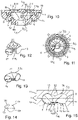
- the Figures 1 to 3 show a shower head with an integrated shower jet generating device, the shower head being usable, for example, as a sanitary hand shower for showers and bathrooms or as a kitchen shower head on kitchen vanities.
- One or more shower jet generation devices according to the invention can be integrated into the shower, one of which is shown in the views of FIG Figures 2 and 3 representative can be seen.
- This and similar showers can also be a shower jet generating device according to the invention.
- the 9 and 10 show the in the shower according to the Figures 1 to 3 integrated shower jet generating device in individual representation
- the Figures 11 to 25 show different variants of this shower jet generating device and its components.
- the Figures 4 to 8 show further possible realizations of the shower jet generation device according to the invention.
- the shower jet generation device includes a housing body 1 with a fluid supply 2 and at least one jet outlet opening 3 on the outlet side, through which, during operation of the shower jet generation device, a shower fluid supplied from the housing body 1 flows as a 3 and 6 schematically indicated shower jet 4 with a main jet direction S H exit.
- the main beam direction S H runs at an acute angle of inclination ⁇ between 0° and 90° with respect to a housing exit direction G A .
- the angle of inclination ⁇ remains less than 90° and is preferably between 0° and 70°, although it can also be zero at times, ie the main beam direction SH is then parallel to the housing exit direction G A at this moment.
- the shower jet 4 in the 3 and 6 with its representative marginal rays 4a, 4b can have a converging beam path, a beam path with a substantially constant diameter or, as shown, a diverging beam path with a beam angle ⁇ between its marginal rays 4a, 4b, and the main beam direction S
- H results from this as the mean or averaged direction of the individual spray components of the shower jet 4 or as a longitudinal central direction of the shower jet 4.
- the respective jet outlet opening 3 of the shower jet generating device can be of any suitable shape, including a conical or stepped narrowing shape or a conical or stepped widening shape in the housing outlet direction GA or a cylindrical shape, each having a circular cross section , as in the examples shown, or alternatively, for example, may have an oval or polygonal cross-section.
- the jet exit opening 3 has a shape that narrows conically in the housing exit direction G A .
- the jet exit opening 3 has a cylindrical shape with an opening diameter that remains constant in the housing exit direction G A .
- the jet exit opening 3 has a shape that widens in stages in the housing exit direction G A .
- the selected shape of the jet outlet opening 3 influences the jet form of the shower jet 4 emerging from it, as will be understood by a person skilled in the art.
- the shower jet generating device includes a jet steering device which is set up to periodically vary the main jet direction SH of the shower jet 4 .
- the jet steering device comprises an orbit 5 which is formed in the housing body 1 and runs annularly around the jet outlet opening 3 and an orbit 5 which is arranged so as to be movable in a circumferential manner on the orbit 5 Jet steering unit 6.
- the main jet direction S H of the shower jet 4 emerging from the housing body 1 through the jet outlet opening 3 changes depending on the current position of the jet steering unit 6 on the orbit 5, i.e. depending on the orbit position of the jet steering unit 6 changing as a result of the orbit movement.
- the housing exit direction G A i.e. the direction in which the shower jet 4 would leave the housing body 1 after passing through the jet exit opening 3 if the jet steering device were not present, generally runs, as in the examples shown, parallel to a longitudinal axis Ls of the jet exit opening 3.
- the jet steering unit 6 rotates on its orbit and thereby periodically changes the main jet direction S H of the shower jet 4 Figures 1 to 3 , 9 and 10 as well as in the Figures 4 to 8 illustrated versions, on a cone shell, whose longitudinal axis of the cone is given by the longitudinal central axis Ls of the jet exit opening 3 or is parallel to the housing exit direction G A .
- the longitudinal axis Ls of the respective jet exit opening 3 is oriented parallel to a longitudinal axis L G of the housing body 1, with specifically in the embodiment of Figures 1 to 3 , 9 and 10 this longitudinal axis L G of the housing body 1 of the shower jet generating device is oriented parallel to a longitudinal axis L B of the shower or of the shower head 20 into which the shower jet generating device is integrated.
- the housing body 1 of the shower jet generation device has a plurality of jet outlet openings 3 .
- the shower jet generating devices according to Figures 4 to 8 each six jet outlet openings 3 1 to 3 6 .
- Each beam exit opening 3 1 to 3 6 is assigned its own revolving path 5 1 to 5 6 running around it and its own beam steering unit 6 1 to 6 6 movably arranged on the revolving path 5 1 to 5 6 .
- the jet steering units 6 1 to 6 6 for the jet exit openings 3 1 to 3 6 are identical, in alternative versions at least two of the jet steering units 6 1 to 6 6 are different from one another designed.
- the Figures 1 to 3 and 9 to 25 illustrate shower jet generating devices, the housing body 1 of which has only a single jet outlet opening 3 together with an orbit 5 and jet steering unit 6 .
- the shower jet generation device comprises only two, three, four or five or more than six jet outlet openings 3, each with an associated orbit 5 and jet steering unit 6.
- the jet deflection unit 6 contains at least one jet deflection body 7, which is moved in a rotating manner on the orbit 5 by the fluid pressure of the supplied shower fluid, which is designed as a rolling body rolling along the orbit 5 or as a sliding body that slides along the orbit 5, and on at least part of its circumference on the Orbit 5 partially engages in an inlet cross-section E Q of the jet outlet opening 3 in a jet direction-steering manner.
- this also includes the possibility that the jet deflection body 7 forms a combined rolling and sliding body that rotates in a combined rolling and sliding movement on the orbit 5 or depending on the circumstances, e.g. the acting fluid pressure and the coefficient of friction between jet deflection body 7 and orbit 5, on orbit 5 executes a rolling movement and/or a sliding movement.
- a single beam steering body 7 which is designed as a rolling ball 7a.
- Its ball diameter is selected in such a way that the roller ball 7a engages in the inlet cross section E Q of the jet outlet opening 3 by a certain amount B Q in a projection onto the inlet cross section E Q of the jet outlet opening 3, i.e. in a projection perpendicular to the longitudinal axis L s of the jet outlet opening 3, ie the dimension B Q is determined as the area proportion of the inlet cross section E Q that is covered or overlapped by the jet deflection body 7 or the jet deflection unit 6, as in FIGS 10, 15 and 16 explicitly represented.
- the proportion of the cross-sectional area of the jet exit opening 3 that is partially covered by the jet steering unit 6, i.e. the intervention dimension BQ, can remain constant or vary during the circulation of the jet steering unit 6, depending on requirements and system design, in particular with regard to the shape of the orbit 5 and the jet steering unit 6, which means a corresponding Consistency or change in the flow rate of shower fluid flowing through the jet outlet opening 3 means. In the examples shown, this flow rate remains constant if the jet outlet opening 3 has a circular cross section and the orbit 5 has a circular shape concentric with the jet outlet opening 3 .
- the orbit 5 and the cross-section of the jet exit opening 3 can have non-conforming shapes, e.g., the orbit 5 has a circular shape and the opening cross-section an elliptical shape or vice versa.
- the course of the main jet direction SH and in particular its angle of inclination ⁇ relative to the housing exit direction G A can be set or specified in the desired manner by appropriate design of the orbit 5 and the jet deflection unit 6 and in particular their jet deflection body 7.
- the definitions required for this can be determined empirically, for example by means of computer simulation and/or simple tests.
- the effect of the jet deflection unit 6 on the main jet direction SH and/or on the jet shape of the exiting shower jet 4 can also be influenced or in a desired manner by selecting an appropriate material and/or an appropriate surface finish for the jet deflection unit 6 or its jet deflection body 7 set, which can also be determined if necessary by means of computer simulation and/or simple tests.
- the 11 and 12 illustrate an embodiment variant in which the jet deflection body 7 is designed as a sliding body sliding along the orbit 5, in the case shown specifically as a sliding body 7b in the shape of a torus segment, which extends over a torus angle of approx. 90° and thus correspondingly over an angle of approx ° extends in the direction of rotation of the orbit 5, alternatively over any other torus angle.
- a diameter d T of this sliding body 7b in the form of a section of a toroidal section is, analogously to the case of the rolling ball 7a explained above, slightly larger than a width W U of the annular orbit 5, so that the sliding body 7b in the form of a section of toroidal section with a radially inner part partially fits into that of the orbiting path 5 surrounding inlet cross-section E Q of the jet outlet opening 3 engages, ie, in turn, covers it by the definable amount B Q .
- the jet deflection body 7 or the jet deflection unit 6 can be provided with a wing structure, which acts as a fluid resistance surface in the manner of a turbine wheel surface in order to support the effect of the fluid pressure of the supplied shower fluid for the movement drive of the jet deflection body 7, as is the case in the form of a wing structure 21 for the toroidal section-shaped sliding body 7b of 11 and 12 is shown.
- the jet deflection body 7 does not have such a wing structure and is caused to rotate by the shower fluid simply by appropriate shaping and flow, as is realized in the other exemplary embodiments shown.
- the fluid supply 2 can be configured in such a way that the shower fluid supplied has a circumferential direction the orbit 5 pointing fluid flow component directed to the jet steering unit 6 or the jet steering body 7.
- the jet steering unit 6 in turn has a toroidal section-shaped sliding body 7c as jet steering body 7, which in this case extends over an angle of approx. 120° and has a flat engagement projection 22 on its radially inner side, with which it partially directs the jet direction engages in the inlet cross section E Q of the jet outlet opening 3 when it is inserted into the housing body 1 of the shower jet generating device. Consequently, in this embodiment variant, the width d T of this sliding body 7c in the form of a segment of a toroidal section does not need to be greater than the width W U of the orbit 5 .
- the jet deflection body 7 shows 14 another possible realization of the jet deflection body 7 as a sliding body 7d, which contains a sliding ball 23, from which an engagement tab 25 protrudes, with which this jet deflection body 7 partially engages in the inlet cross section E Q of the associated jet outlet opening 3 when it is on the orbit 5 .
- the gripping tab 25 has a gripping front face 26 that is curved in conformance with, for example, a circular border of the jet outlet opening 3 and can be advantageous for forming a corresponding cross section of the shower jet 4 .
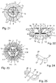
- the beam steering unit 6 has a plurality of beam steering bodies 7 which are arranged circumferentially along the orbit 5 and are decoupled from one another or coupled to one another. So comprises the beam steering unit 6 in the embodiments according to the Figures 7 and 8 , 19 and 20 such as 22 and 23 three jet deflection bodies 7 1 , 7 2 , 7 3 per jet exit opening 3 , while in the other examples shown it includes only one jet deflection body 7 per jet exit opening 3 . It goes without saying that in alternative embodiments, the beam steering unit 6 can have two or more than three beam steering bodies 7 .
- the respective beam deflection body 7 is free, ie without forced guidance by a bearing, rolling and/or sliding along the orbit 5 arranged, as in the embodiments according to Figures 1 to 16 .
- the three jet deflection bodies 7 1 , 7 2 , 7 3 per jet outlet opening 3 are each formed by a roller ball 7a, of which two roller balls have the same diameter and one roller ball has a larger diameter in comparison and which are loosely inserted into the orbit 5.
- the diameters of the three spherical jet deflection bodies 7 1 , 7 2 , 7 3 can be chosen differently as required, eg all diameters are the same size or all three diameters are different sizes.
- the beam steering unit 6 has a rotary guide 8 for the respective beam steering body 7, as in the exemplary embodiments of FIG Figures 17 to 25 .
- the rotary guide 8 is in the examples Figures 17 to 23 formed as a rotary bearing with a housing-fixed bearing pin 18 as a hub and a bearing sleeve 19 held thereon so as to be rotatable.
- three approximately hemispherical shell bodies 17a, 17b, 17c protrude radially outwards from the bearing sleeve 19 at preferably the same, alternatively different, angular distances, which in this case form the part of the jet steering unit 6 that is active for jet steering and, in turn, each in turn partially steers the jet direction into the inlet cross section E Q of the Jet exit opening 3 intervene.
- a rolling and/or sliding ball 17d is inserted, which moves radially outwards against a wall 16 of the housing body 1 that delimits the orbit 5 radially outwards
- shower jet generating device is supported and rolls on the orbit 5 and / or slides.
- the beam steering unit 6 forms the in this embodiment 17 and 18 overall, in turn, a beam deflection body 7 that rolls and/or slides along the orbit and is rotatably mounted.
- the shell bodies 17a, 17b, 17c are embodied as sliding bodies, which slide along the orbit 5 and can therefore each be referred to as a sliding, rotatably mounted beam deflection body 7 .
- the one or more rolling and/or sliding balls 17d can then be omitted.
- 19 and 20 are radially from the bearing sleeve 19 to the outside with turn preferably equidistant 120 ° angular distance from each other from three spherical sliding bodies, which slidably rotate on the orbit 5 and analogous to the rolling ball versions in the examples of FIG Figures 1 to 10 partially engage in the inlet cross-section E Q of the jet outlet opening 3 in a jet direction-steering manner, so that they each form a sliding, spherical jet deflection body 7 1 , 7 2 , 7 3 and overall represent a rotatably mounted, sliding realization of the jet deflection unit 6 .
- FIG. 21 shows a variant that of that of 19 and 20 with the difference that the spherical jet deflection bodies 7 1 , 7 2 , 7 3 are not arranged at an equidistant angular distance from one another, but rather in succession in the circumferential direction with physical contact. This results in a compared to that of the embodiment of 19 and 20 correspondingly modified jet shape of the shower jet 4 emerging from the jet outlet opening 3.
- the jet deflection unit 6 includes a star-shaped jet deflection body 7 protruding radially outwards from the bearing sleeve 19 with three arms 14a, 14b, 14c, preferably arranged at equidistant angular intervals, which in turn partially engage in the inlet cross-section E Q of the jet outlet opening 3 and radially on the outside at the same height as directing the jet of orbit 5 end in circular ball receiving areas, each with a circular opening, in each of which a sliding and/or rolling ball 13 with a larger ball diameter than the opening is received in such a way that it sits on orbit 5 and this slides and/or rolls and on star-shaped beam steering body 7 is performed.
- This star-shaped beam deflection body 7 can thus circulate on the orbit 5 in a sliding and/or rolling manner via the sliding/rolling balls 13 .
- the 24 shows another possible design for the jet deflection body 7.
- the jet deflection body 7 consists of a sliding ball 24, which is set up for sliding rotation on the associated orbit 5, and an engagement web 27 protruding from this sliding ball 24, with which this jet deflection body 7 is partially engages in the inlet cross-section E Q of the associated jet outlet opening 3 and which, at its end region opposite the sliding ball 24, has a jet direction-steering oblique bore 28, the bore longitudinal axis of which obliquely to a vertical axis of the engagement web 27 and thus to the longitudinal axis Ls of the associated jet outlet opening 3 and the main jet direction S H of the shower jet 4 is determined by the shower fluid flowing through the inclined bore 28 before it passes through the jet outlet opening 3.
- the jet deflection body 7 in this example has a guide or bearing pin 31 with which it can be rotatably mounted on an associated bearing pin receptacle provided fixed to the housing body 1 of the shower jet generating device, which in turn results in a corresponding pivot bearing for the jet deflection body 7. which guides it mounted on the orbit 5 in its rotating orbital motion with the rolling/sliding ball 30 .
- a fluid chamber 9 is formed in the housing body 1, in which the orbit 5 is located and from which the jet outlet opening 3 opens on a chamber side 9a pointing axially in the housing outlet direction G A .
- the fluid chamber 9 is delimited on this chamber side 9a by a circulation guide surface 5a of the circulation path 5 which annularly surrounds the jet outlet opening 3 .
- the jet steering unit 6 is supported on this circulation guide surface 5a, for example with its jet steering body 7, as explained above.
- the fluid chamber 9 is delimited by a partition 10, which has at least one fluid supply opening 11 into the fluid chamber 9 as part of the fluid supply 2 of the housing body 1 for the shower fluid.
- the wall or surface areas that delimit the fluid chamber 9, and in particular those wall or surface areas that delimit or define the orbit 5, are suitably designed in their course or their shape in each case adapted to the requirements.
- the circulation guide surface 5a as well as the opposite wall surface of the partition wall 10 and the wall surface of the housing body 1 delimiting the circulation path 5 radially outwards can each have a shape adapted to the cross-sectional shape of the beam deflection unit 6 rotating on the circulation path 5 or its beam deflection body 7 and/or have a curved or straight shape. This means that corresponding modifications of the forms of these boundary surfaces realized in the examples shown are possible in alternative realizations as required.
- the circulating guide surface 5a of the circulating path 5 has a delimitation region 12 radially inward towards the jet outlet opening 3, which extends with a directional component opposite to the housing outlet direction G A , as is the case in the examples in FIG 15 and 16 is realized. This can support the safe guidance of the beam steering unit 6 or its beam steering body 7 when circulating on the orbit 5 .
- the partition wall 10 includes a boundary wall region 32 radially inward towards the jet outlet opening, which extends with a directional component in the housing outlet direction G A , as is also the case in the exemplary embodiments of FIGS 15 and 16 is realized.
- This also supports the safe guidance of the beam steering unit 6 or its beam steering body 7 when circulating on the orbit 5.
- the boundary region 12 and the boundary wall region 32 can also act individually or in combination as a barrier that prevents the beam steering unit 6 or its beam steering body 7 is unintentionally moved radially inwards and the jet outlet opening 3 is blocked completely or at least to an extent that is not desired.
- a limiting pin 33 protrudes from the partition wall 10 in the housing exit direction G A into the fluid chamber 9, which limits the orbit 5 for the jet steering unit 6 radially inward, as is the case in the exemplary embodiments of FIG Figures 1 to 10 is realized.
- the limiting pin 33 secures in the examples mentioned, the beam steering unit 6 and in particular its beam steering body 7 against unintentional deviation from the orbit 5 radially inwards and in this way keeps the beam steering unit 6 or the beam steering body 7 on the orbit 5.
- the bearing pin 18 already mentioned for the rotary bearing or rotary guide 8, on which the beam steering unit 6 is mounted in a rotationally movable manner protrudes from the partition 10 in the housing outlet direction G A into the fluid chamber 9, as is the case in the exemplary embodiments of FIG Figures 17 to 23 the case is.
- the housing body 1 of the shower jet generating device has, as in the exemplary embodiments shown, a base body 1a, which contains the jet outlet opening 3 and the circulation guide surface 5a of the circulation path 5 surrounding it in the form of a ring, and a cover body 1b containing the partition wall 10, which is connected to the base body 1a is detachably or permanently connected.
- the housing body 1 of the shower jet generating device can be constructed from more than two housing parts.
- the invention provides a shower jet generation device which, during shower operation, enables a periodic change in the shower jet direction in a structurally simple and functionally reliable manner.
- This can be used, for example, to provide a shower that has one or more such shower jet generating devices and is therefore able to deliver a supplied shower fluid as an overall shower jet with a massage effect formed from the shower jet(s) generated by these shower jet generating devices.
Applications Claiming Priority (1)
| Application Number | Priority Date | Filing Date | Title |
|---|---|---|---|
| DE102020215025.7A DE102020215025A1 (de) | 2020-11-30 | 2020-11-30 | Brausestrahlerzeugungsvorrichtung für richtungsvariablen Brausestrahl |
Publications (1)
| Publication Number | Publication Date |
|---|---|
| EP4005681A1 true EP4005681A1 (fr) | 2022-06-01 |
Family
ID=78789867
Family Applications (1)
| Application Number | Title | Priority Date | Filing Date |
|---|---|---|---|
| EP21210507.6A Withdrawn EP4005681A1 (fr) | 2020-11-30 | 2021-11-25 | Dispositif de génération de jet de douche pour jets de douche à direction variable |
Country Status (3)
| Country | Link |
|---|---|
| EP (1) | EP4005681A1 (fr) |
| CN (1) | CN114570538A (fr) |
| DE (1) | DE102020215025A1 (fr) |
Citations (12)
| Publication number | Priority date | Publication date | Assignee | Title |
|---|---|---|---|---|
| US4018385A (en) | 1975-11-06 | 1977-04-19 | Leonard Bruno | Oscillating spray head |
| US4089471A (en) | 1976-01-29 | 1978-05-16 | Incontrol Industries Ltd. | Pulsating shower heads |
| GB2202764A (en) * | 1987-04-03 | 1988-10-05 | Ilan Greenberg | Variable-spray shower head |
| DE3915962C1 (en) | 1989-05-17 | 1990-09-13 | Fraunhofer-Gesellschaft Zur Foerderung Der Angewandten Forschung Ev, 8000 Muenchen, De | Adjustable high-pressure cleaning jet - has ball rotated by turbine blades and held in movable bearing |
| EP0478999A1 (fr) * | 1990-10-04 | 1992-04-08 | Friedrich Grohe Aktiengesellschaft | Tête de douche |
| US5332155A (en) | 1992-03-28 | 1994-07-26 | Jaeger Anton | Rotor nozzle for high pressure cleaning apparatus |
| DE3736795C2 (de) | 1987-09-25 | 1999-05-06 | Oras Oy | Handbrause für kontinuierlichen und pulsierenden Wasserstrahl |
| DE19912104A1 (de) | 1999-03-18 | 2000-09-21 | Hansgrohe Ag | Brausekopf für eine sanitäre Brause |
| EP1234615A2 (fr) * | 2001-02-21 | 2002-08-28 | Friedrich Grohe AG & Co. KG | Pommeau de douche |
| DE10231575A1 (de) | 2002-07-11 | 2004-01-29 | Grohe Water Technology Ag & Co. Kg | Brausekopf für Sanitärbrausen |
| DE102005002424A1 (de) | 2005-01-18 | 2006-07-27 | Grohe Ag | Brause |
| CN109201359A (zh) * | 2017-07-04 | 2019-01-15 | Sanei株式会社 | 出水部的构造和淋浴装置 |
-
2020
- 2020-11-30 DE DE102020215025.7A patent/DE102020215025A1/de active Pending
-
2021
- 2021-11-25 EP EP21210507.6A patent/EP4005681A1/fr not_active Withdrawn
- 2021-11-30 CN CN202111441416.3A patent/CN114570538A/zh active Pending
Patent Citations (14)
| Publication number | Priority date | Publication date | Assignee | Title |
|---|---|---|---|---|
| US4018385A (en) | 1975-11-06 | 1977-04-19 | Leonard Bruno | Oscillating spray head |
| US4089471A (en) | 1976-01-29 | 1978-05-16 | Incontrol Industries Ltd. | Pulsating shower heads |
| GB2202764A (en) * | 1987-04-03 | 1988-10-05 | Ilan Greenberg | Variable-spray shower head |
| DE3736795C2 (de) | 1987-09-25 | 1999-05-06 | Oras Oy | Handbrause für kontinuierlichen und pulsierenden Wasserstrahl |
| DE3915962C1 (en) | 1989-05-17 | 1990-09-13 | Fraunhofer-Gesellschaft Zur Foerderung Der Angewandten Forschung Ev, 8000 Muenchen, De | Adjustable high-pressure cleaning jet - has ball rotated by turbine blades and held in movable bearing |
| EP0478999A1 (fr) * | 1990-10-04 | 1992-04-08 | Friedrich Grohe Aktiengesellschaft | Tête de douche |
| DE4031206A1 (de) | 1990-10-04 | 1992-04-09 | Grohe Armaturen Friedrich | Brausekopf |
| US5332155A (en) | 1992-03-28 | 1994-07-26 | Jaeger Anton | Rotor nozzle for high pressure cleaning apparatus |
| DE19912104A1 (de) | 1999-03-18 | 2000-09-21 | Hansgrohe Ag | Brausekopf für eine sanitäre Brause |
| EP1234615A2 (fr) * | 2001-02-21 | 2002-08-28 | Friedrich Grohe AG & Co. KG | Pommeau de douche |
| DE10108326A1 (de) | 2001-02-21 | 2002-08-29 | Grohe Armaturen Friedrich | Brausekopf |
| DE10231575A1 (de) | 2002-07-11 | 2004-01-29 | Grohe Water Technology Ag & Co. Kg | Brausekopf für Sanitärbrausen |
| DE102005002424A1 (de) | 2005-01-18 | 2006-07-27 | Grohe Ag | Brause |
| CN109201359A (zh) * | 2017-07-04 | 2019-01-15 | Sanei株式会社 | 出水部的构造和淋浴装置 |
Also Published As
| Publication number | Publication date |
|---|---|
| DE102020215025A1 (de) | 2022-06-02 |
| CN114570538A (zh) | 2022-06-03 |
Similar Documents
| Publication | Publication Date | Title |
|---|---|---|
| EP2796205B1 (fr) | Pomme de douche à mouvement rotatif pouvant être bloqué par une came de commande | |
| EP0826426B1 (fr) | Arroseur | |
| EP0698417B1 (fr) | Arroseur pour la distribution d'un fluide | |
| DE2911405C2 (de) | Massagebrause mit einer Einrichtung zur wahlweisen Erzeugung pulsierender und/oder nicht pulsierender Flüssigkeitsstrahlen | |
| DE102011013534B3 (de) | Strahlbildnerelement für einen Brausekopf | |
| EP0379654B1 (fr) | Injecteur rotatif pour outil de nettoyage haute pression | |
| EP0836888B1 (fr) | Pomme de douche | |
| EP2988876B1 (fr) | Pomme de douche à disque de commande rotatif | |
| DE2911936C2 (de) | Auf unterschiedliche Strahlen einstellbare Brause | |
| DE2140526A1 (de) | Duschbrause | |
| DE4329616A1 (de) | Regner, insbesondere zur Vegetations-Bewässerung | |
| CH618894A5 (fr) | ||
| DE10006864B4 (de) | Reinigungsdüse | |
| EP0372182A2 (fr) | Buse de rotor pour appareil de nettoyage à haute pression | |
| EP1036597B1 (fr) | Pomme d'arrosoir pour une douche sanitaire | |
| DE19511820A1 (de) | Rotordüse, insbesondere für ein Hochdruckreinigungsgerät | |
| EP1259331B1 (fr) | Tete de pulverisation | |
| DE2736314C3 (de) | Düse zum Versprühen eines unter Druck stehenden Mediums | |
| DE4221587C2 (de) | Rotordüse, insbesondere für ein mit Reinigungsflüssigkeit arbeitendes Hochdruckreinigungsgerät | |
| DE2409315B2 (de) | Sprühdüse | |
| DE10034818A1 (de) | Brause | |
| EP4005681A1 (fr) | Dispositif de génération de jet de douche pour jets de douche à direction variable | |
| DE2644765A1 (de) | Spruehkopf mit pulsierendem strahl | |
| DE1609199A1 (de) | Brausekopf | |
| EP0900597A2 (fr) | Douche de massage |
Legal Events
| Date | Code | Title | Description |
|---|---|---|---|
| PUAI | Public reference made under article 153(3) epc to a published international application that has entered the european phase |
Free format text: ORIGINAL CODE: 0009012 |
|
| STAA | Information on the status of an ep patent application or granted ep patent |
Free format text: STATUS: THE APPLICATION HAS BEEN PUBLISHED |
|
| AK | Designated contracting states |
Kind code of ref document: A1 Designated state(s): AL AT BE BG CH CY CZ DE DK EE ES FI FR GB GR HR HU IE IS IT LI LT LU LV MC MK MT NL NO PL PT RO RS SE SI SK SM TR |
|
| STAA | Information on the status of an ep patent application or granted ep patent |
Free format text: STATUS: THE APPLICATION IS DEEMED TO BE WITHDRAWN |
|
| 18D | Application deemed to be withdrawn |
Effective date: 20221202 |