EP4004292B1 - Pfahl und verfahren zur herstellung eines pfahls - Google Patents
Pfahl und verfahren zur herstellung eines pfahls Download PDFInfo
- Publication number
- EP4004292B1 EP4004292B1 EP20753981.8A EP20753981A EP4004292B1 EP 4004292 B1 EP4004292 B1 EP 4004292B1 EP 20753981 A EP20753981 A EP 20753981A EP 4004292 B1 EP4004292 B1 EP 4004292B1
- Authority
- EP
- European Patent Office
- Prior art keywords
- hollow body
- pile
- elongated hollow
- soil
- attached
- Prior art date
- Legal status (The legal status is an assumption and is not a legal conclusion. Google has not performed a legal analysis and makes no representation as to the accuracy of the status listed.)
- Active
Links
Images

Classifications
-
- E—FIXED CONSTRUCTIONS
- E02—HYDRAULIC ENGINEERING; FOUNDATIONS; SOIL SHIFTING
- E02D—FOUNDATIONS; EXCAVATIONS; EMBANKMENTS; UNDERGROUND OR UNDERWATER STRUCTURES
- E02D5/00—Bulkheads, piles, or other structural elements specially adapted to foundation engineering
- E02D5/22—Piles
- E02D5/24—Prefabricated piles
- E02D5/28—Prefabricated piles made of steel or other metals
- E02D5/285—Prefabricated piles made of steel or other metals tubular, e.g. prefabricated from sheet pile elements
-
- E—FIXED CONSTRUCTIONS
- E02—HYDRAULIC ENGINEERING; FOUNDATIONS; SOIL SHIFTING
- E02D—FOUNDATIONS; EXCAVATIONS; EMBANKMENTS; UNDERGROUND OR UNDERWATER STRUCTURES
- E02D15/00—Handling building or like materials for hydraulic engineering or foundations
- E02D15/08—Sinking workpieces into water or soil inasmuch as not provided for elsewhere
-
- E—FIXED CONSTRUCTIONS
- E02—HYDRAULIC ENGINEERING; FOUNDATIONS; SOIL SHIFTING
- E02D—FOUNDATIONS; EXCAVATIONS; EMBANKMENTS; UNDERGROUND OR UNDERWATER STRUCTURES
- E02D27/00—Foundations as substructures
- E02D27/32—Foundations for special purposes
- E02D27/52—Submerged foundations, i.e. submerged in open water
- E02D27/525—Submerged foundations, i.e. submerged in open water using elements penetrating the underwater ground
-
- E—FIXED CONSTRUCTIONS
- E02—HYDRAULIC ENGINEERING; FOUNDATIONS; SOIL SHIFTING
- E02D—FOUNDATIONS; EXCAVATIONS; EMBANKMENTS; UNDERGROUND OR UNDERWATER STRUCTURES
- E02D3/00—Improving or preserving soil or rock, e.g. preserving permafrost soil
- E02D3/11—Improving or preserving soil or rock, e.g. preserving permafrost soil by thermal, electrical or electro-chemical means
- E02D3/115—Improving or preserving soil or rock, e.g. preserving permafrost soil by thermal, electrical or electro-chemical means by freezing
-
- E—FIXED CONSTRUCTIONS
- E02—HYDRAULIC ENGINEERING; FOUNDATIONS; SOIL SHIFTING
- E02D—FOUNDATIONS; EXCAVATIONS; EMBANKMENTS; UNDERGROUND OR UNDERWATER STRUCTURES
- E02D5/00—Bulkheads, piles, or other structural elements specially adapted to foundation engineering
- E02D5/22—Piles
- E02D5/54—Piles with prefabricated supports or anchoring parts; Anchoring piles
-
- E—FIXED CONSTRUCTIONS
- E02—HYDRAULIC ENGINEERING; FOUNDATIONS; SOIL SHIFTING
- E02D—FOUNDATIONS; EXCAVATIONS; EMBANKMENTS; UNDERGROUND OR UNDERWATER STRUCTURES
- E02D7/00—Methods or apparatus for placing sheet pile bulkheads, piles, mouldpipes, or other moulds
- E02D7/18—Placing by vibrating
-
- E—FIXED CONSTRUCTIONS
- E02—HYDRAULIC ENGINEERING; FOUNDATIONS; SOIL SHIFTING
- E02D—FOUNDATIONS; EXCAVATIONS; EMBANKMENTS; UNDERGROUND OR UNDERWATER STRUCTURES
- E02D7/00—Methods or apparatus for placing sheet pile bulkheads, piles, mouldpipes, or other moulds
- E02D7/24—Placing by using fluid jets
-
- E—FIXED CONSTRUCTIONS
- E02—HYDRAULIC ENGINEERING; FOUNDATIONS; SOIL SHIFTING
- E02D—FOUNDATIONS; EXCAVATIONS; EMBANKMENTS; UNDERGROUND OR UNDERWATER STRUCTURES
- E02D7/00—Methods or apparatus for placing sheet pile bulkheads, piles, mouldpipes, or other moulds
- E02D7/26—Placing by using several means simultaneously
-
- E—FIXED CONSTRUCTIONS
- E02—HYDRAULIC ENGINEERING; FOUNDATIONS; SOIL SHIFTING
- E02D—FOUNDATIONS; EXCAVATIONS; EMBANKMENTS; UNDERGROUND OR UNDERWATER STRUCTURES
- E02D7/00—Methods or apparatus for placing sheet pile bulkheads, piles, mouldpipes, or other moulds
- E02D7/28—Placing of hollow pipes or mould pipes by means arranged inside the piles or pipes
Definitions
- the present invention relates to a pile system and a method for installing a pile according to the preambles of the appended independent claims, and generally known from EP 0 962 596 A1 .
- piles are known in the prior art to provide support for a structure by transferring its load through compressible strata or water onto layers of soil or rock that have sufficient bearing capacity and suitable settlement characteristics.
- Piles are typically formed by long, columnar elements made from steel or reinforced concrete.
- Percussion drivers, hydraulic drivers, vibratory drivers and rotary augers are typically used to install piles into the ground.
- Piles may be classified by their basic design function or by their method of construction.
- An end-bearing pile develops most of its friction at the toe of the pile, bearing on a hard layer.
- the end-bearing pile transmits load directly to firm strata and receives lateral restraint from subsoil.
- a friction pile develops most of the pile-bearing capacity by shear stresses along the sides of the pile and is suitable where harder layers are too deep.
- the friction pile transmits load to surrounding soil by friction between the surface of the pile and soil.
- a driven pile is driven, jacked, vibrated or screwed into the ground, displacing the material around the pile outwards and downwards instead of removing it.
- the driven pile is often used in offshore applications.
- a bored pile removes soil to form a hole for the pile which is poured in situ.
- the bored pile is used primarily in cohesive subsoils for the formation of friction piles and when forming pile foundations close to existing buildings.
- a screw pile has a helix near the pile toe so it can be screwed into the ground.
- a problem associated with known piles is that they are difficult and time-consuming to install into the ground. Another problem associated with the known piles is that they are difficult or even impossible to remove from the ground. Yet another problem of the known piles is that they are not versatile, but instead can only be used in some specific applications.
- EP 0962596 A1 describes a pile and a method for installing a pile.
- CN 105951826 B describes a suction ground anchor device in a tubular pile and a water pressure injection method thereof.
- JP 2014047532 A describes a sampling device for a filler sample in a bored hole.
- WO 2013/081455 A1 describes an excavator device for excavating bottom parts from a bottom floor inside a ground structure.
- a pile comprises a first elongated hollow body having a first end and a second end, the first end being closed by an end member provided with an opening, and a second elongated hollow body having a first end and a second end, the second elongated hollow body being arranged inside the first elongated hollow body so that the first end of the second elongated hollow body extends through the opening and is attached to the end member.
- the pile has two elongated hollow bodies inside each other.
- the first elongated hollow body forms the outer body and the second elongated hollow body the inner body of the pile.
- the first and second elongated hollow bodies are essentially parallel with each other and have essentially the same length.
- the second elongated hollow body is arranged concentrically with the first elongated hollow body.
- the first elongated hollow body is preferably tubular and has either a circular or rectangular cross section.
- the first elongated hollow body can be a pipe, a tube or a stiffened shell.
- the first end of the first elongated hollow body is closed by the end member, which comprises the opening through which the first end of the second elongated hollow body passes.
- the end member is preferably attached inside the first end of the first elongated hollow body.
- the end member is attached to the first and second elongated hollow bodies in a watertight manner.
- the end member is preferably convergent towards the point where the end member is attached to the second elongated hollow body.
- the second end of the first elongated hollow body can be open.
- the second end of the first elongated hollow body can be closed by another end member provided with an opening through which the second end of the second elongated hollow body is arranged to extend.
- the second elongated hollow body is preferably attached to this end member.
- the second ends of the first and second elongated hollow bodies can be hermetically closed by a cover, which prevents material from passing into and out of the pile.
- the wall thickness of the first elongated hollow body can be, for example, 10-100 mm.
- the second elongated hollow body is preferably tubular and has a circular cross section.
- the second elongated hollow body can be a pipe or a tube.
- the first end of the second elongated hollow body is open allowing soil to be conveyed through the second elongated hollow body when the pile is installed into the ground.
- the second end of the second elongated hollow body is open, but it can be closed after the pile has been installed into the ground.
- the wall thickness of the second elongated hollow body can be, for example, 5-50 mm.
- the pile is a columnar element, which can be made of steel, stainless steel, titanium, concrete, reinforced plastics or other durable materials.
- the pile can be installed or driven into the ground.
- the pile can be installed on dry land or into the bottom of water, such as into a seabed.
- the pile can be installed into the seabed so that its upper end is either above or below the sea surface.
- the pile can have a modular structure, wherein the pile is formed of a plurality of pile sections attached sequentially to each other.
- the length of the pile can be, for example, less than 200 m. Preferably, the length of the pile is 20-100 m.
- the diameter of the pile can be, for example, 2-10 m.
- the pile can be installed into the ground as follows. First, the pile is arranged or lowered in a vertical orientation on the ground so that the first ends of the elongated hollow bodies are towards the ground. Then, the soil under the lower end of the pile is dredged with a dredge pump that is attached to the first end of the second elongated hollow body, and the dredged soil is removed through the second elongated hollow body.
- the space between the first elongated hollow body and the second elongated hollow body can be filled with the removed soil or other suitable material through the upper end of the pile.
- the pile is drawn into the ground. The soil is dredged and removed until the pile is at a desired depth in the ground.
- the pile can be removed from the ground, for example, by pumping water through the second elongated hollow body underneath the lower end of the pile. As the water is pumped underneath the lower end of the pile, the pile starts to rise from the ground.
- the pile can be used to provide support for a structure by transferring its load through compressible strata or water onto layers of soil or rock that have sufficient bearing capacity and suitable settlement characteristics. The friction between the first elongated hollow body and the soil may be taken into account in determination of the bearing capacity of the pile.
- the pile can be used, for example, to support docks, quays and wharves.
- the piles can be attached together to form a pile wall.
- the piles are attached at their sides to each other.
- the piles can be attached to each other before or after they have been installed into the ground.
- the number of the piles in the pile wall can be, for example, 2-50.
- the pile wall can be arranged to a closed shape, such as to a circular form.
- the diameter of the closed shape can be, for example, 5-100 m.
- An advantage of the pile is that it is easy and quick to install into the ground. Another advantage of the pile is that it can be easily removed from the ground. Yet another advantage of the pile is that it can be reused. Yet another advantage of the pile is that it is versatile, allowing it to be used in various applications, such as offshore applications.
- the second end of the first elongated hollow body is open allowing a space between the first elongated hollow body and the second elongated hollow body to be filled with ballast.
- the space can be filled during the installation of the pile into the ground.
- the space can be filled, for example, with the dredged soil, gravel, stones, sand, water, cement or barite slurry, or with any combination of these.
- the pile comprises a plurality of outer supports attached to an outer surface of the first elongated hollow body.
- the outer supports may comprise plates, arms or rods.
- the outer supports may extend perpendicularly outwards from the outer surface of the first elongated hollow body.
- the outer supports are preferably attached to a position where the outer supports become at least partly embedded into the ground when the pile is installed.
- the outer supports are arranged symmetrically around the first elongated hollow body and at the same distance from the second end of the first elongated hollow body.
- the number of the outer supports can be, for example, 2-10.
- the pile comprises a plurality of inner supports attached between an inner surface of the first elongated hollow body and an outer surface of the second elongated hollow body.
- the inner supports may comprise plates, arms or rods.
- the inner supports may extend perpendicularly between the inner surface of the first elongated hollow body and the outer surface of the second elongated hollow body.
- the inner supports can be arranged at various locations along the length of the pile. At each location, a plurality of inner supports can be arranged symmetrically around the second elongated hollow body.
- the number of the inner supports can be, for example, 2-50, 50-1000 or 1000-3000.
- the end member comprises a conical portion.
- the conical portion can be arranged so that it opens away from the pile.
- An advantage of the conical portion is that it directs the soil towards the first end of the second elongated hollow body.
- the pile comprises heat transferring means arranged inside the second elongated hollow body for heating and/or cooling the pile.
- the heat transferring means are arranged inside the second elongated hollow body after the pile has been installed into the ground.
- the heat transferring means may comprise heat pipes for transferring heat.
- the present invention relates to a pile system for installing a pile into the ground.
- the pile system according to the invention comprises a pile that comprises a first elongated hollow body having a first end and a second end, the first end being closed by an end member provided with an opening, and a second elongated hollow body having a first end and a second end, the second elongated hollow body being arranged inside the first elongated hollow body so that the first end of the second elongated hollow body extends through the opening and is attached to the end member, a dredge pump attached to the first end of the second elongated hollow body for dredging soil, and a riser pipe arranged inside the second elongated hollow body for carrying the dredged soil, a first end of the riser pipe being attached to the dredge pump.
- the dredge pump is releasably attached to the second elongated hollow body so that it can be removed through the second elongated hollow body after the pile has been installed into the ground.
- the dredge pump is attached to the first end of the second elongated hollow body with a connector that provides a watertight connection between the dredge pump and the second elongated hollow body.
- the riser pipe carries the dredged soil through the second elongated hollow body.
- a second end of the riser pipe can be attached to a tank outside the pile for receiving the dredged soil.
- the riser pipe can be made of steel, stainless steel, or any other suitable material.
- the riser pipe can be a reinforced hose.
- the pile can be installed into the ground as follows. First, the pile is arranged or lowered in a vertical orientation on the ground so that the first ends of the elongated hollow bodies are towards the ground. Then, the soil under the lower end of the pile is dredged with the dredge pump, and the dredged soil is removed through the riser pipe. As the soil is removed from underneath the lower end of the pile, the pile is drawn into the ground. The soil is dredged and removed until the pile is at a desired depth in the ground. Finally, the dredge pump and the riser pipe can be removed from the pile.
- An advantage of the pile system according to the invention is that the pile can be easily and quickly installed into the ground.
- the dredge pump comprises a cutter unit for loosening the soil.
- the cutter unit may comprise rotating cutting or stirring blades driven for example by a hydraulic motor.
- An advantage of the cutter unit is that it facilitates the installation of the pile into the ground.
- the dredge pump comprises a water spraying unit for fluidising the soil.
- the water spraying unit may comprise nozzles to distribute pressurised water.
- An advantage of the water spraying unit is that it facilitates the installation of the pile into the ground.
- the pile system comprises a plurality of water spraying pipes for fluidising the soil.
- the water spraying pipes may comprise nozzles to distribute pressurised water.
- the pile system comprises vibrating means attached to the first elongated hollow body or the second elongated hollow body for vibrating the pile.
- the vibrating means can comprise an eccentric-type vibrator.
- the vibrating means can be configured to vibrate the pile at a frequency of 0.5-50 Hz.
- An advantage of the vibrating means is that they facilitate the installation of the pile into the ground.
- a pile wall comprises a plurality of piles attached to one another.
- the piles are attached to one another at their sides.
- the piles can be attached to one another, for example, by welding or by interlocking sections.
- the piles can be attached to one another before or after they have been installed into the ground.
- the number of piles in the pile wall can be, for example, 2-50.
- the plurality of piles can be arranged in a circular form.
- the diameter of the circular form can be, for example, 5-100 m.
- the present invention also relates to a method for installing a pile into the ground, the pile comprising a first elongated hollow body having a first end and a second end, the first end being closed by an end member provided with an opening, and a second elongated hollow body having a first end and a second end, the second elongated hollow body being arranged inside the first elongated hollow body so that the first end of the second elongated hollow body extends through the opening and is attached to the end member.
- the method according to the invention comprises arranging the pile in a vertical orientation on the ground, using a dredge pump attached to the first end of the second elongated hollow body to dredge soil, and using a riser pipe arranged inside the second elongated hollow body to carry the dredged soil.
- the pile is arranged on the ground so that the first ends of the elongated hollow bodies are towards the ground.
- the dredge pump is used to dredge the soil under the lower end of the pile.
- the dredged soil is drawn from the dredge pump through the riser pipe that is arranged inside the second elongated hollow body. As the soil is removed from underneath the lower end of the pile, the pile is drawn into the ground. The soil is dredged and removed until the pile is at a desired depth in the ground.
- An advantage of the method according to the invention is that the pile can be easily and quickly installed into the ground.
- the method comprises vibrating the pile.
- the pile can be vibrated at a frequency of 0.5-50 Hz.
- the pile can be vibrated with an eccentric-type vibrator that is attached to the first elongated hollow body or the second elongated hollow body.
- the method comprises filling a space between the first elongated hollow body and the second elongated hollow body with ballast.
- the space can be filled during the installation of the pile into the ground.
- the space between the first elongated hollow body and the second elongated hollow body can be filled with the removed soil through the upper end of the pile.
- the space can be filled, for example, with gravel, stones, sand, water, cement or barite slurry, or with any combination of these.
- the method comprises removing the dredge pump and the riser pipe from the pile and sealing the second ends of the first elongated hollow body and the second elongated hollow body with a cover.
- the cover prevents any material from passing into and out of the pile.
- the method comprises arranging heat transferring means inside the second elongated hollow body.
- the heat transferring means are arranged inside the second elongated hollow body after the pile has been installed into the ground.
- the heat transferring means are configured to heat and/or cool the pile.
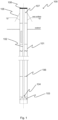
- Fig. 1 illustrates a cross sectional view of a pile.
- the pile 100 has been installed in a vertical orientation into the seabed so that its upper end is above the sea surface.
- the pile 100 comprises two elongated hollow bodies 101, 102 inside each other.
- the first (i.e. outer) elongated hollow body 101 is closed at its first end by a conical end member 103 that is provided with an opening 104.
- the conical end member 103 is attached inside the first end of the first elongated hollow body 101.
- the second (i.e. inner) elongated hollow body 102 is arranged inside the first elongated hollow body 101 in such a manner that a first end of the second elongated hollow body 102 extends through the opening 104 and is attached to the conical end member 103.
- the pile 100 comprises outer supports 105, which are attached to an outer surface of the first elongated hollow body 101.
- the outer supports 105 extend perpendicularly outwards from the outer surface of the first elongated hollow body 101 and are arranged at the same distance from the upper end of the pile 100.
- the pile 100 also comprises inner supports 106 attached between an inner surface of the first elongated hollow body 101 and an outer surface of the second elongated hollow body 102.
- the inner supports 106 extend perpendicularly between the inner surface of the first elongated hollow body 101 and the outer surface of the second elongated hollow body 102 and are arranged at various locations along the length of the pile 100.
- the space 107 between the first elongated hollow body 101 and the second elongated hollow body 102 has been filled with dredged soil during the installation of the pile 100 into the seabed. After the installation of the pile 100, the upper end of the pile 100 has been closed by a cover 108, which prevents material from passing into and out of the pile 100.
- Fig. 2 illustrates a cross sectional view of a pile system according to an embodiment of the invention.
- the pile according to fig. 1 is installed into the seabed.
- the pile system comprises a dredge pump 201 that is attached to the first end of the second elongated hollow body 102.
- the dredge pump 201 is used for dredging soil under the lower end of the pile 100.
- the dredge pump 201 is releasably attached to the second elongated hollow body 102 so that it can be removed through the second elongated hollow body 102 after the pile 100 has been installed into the seabed.
- the dredge pump 201 comprises a cutter unit 202 for loosening the soil and a water spraying unit 203 for fluidising the soil.
- the cutter unit 202 and the water spraying unit 203 facilitate the dredging and thus the installation of the pile 100 into the seabed.
- the pile system also comprises water spraying pipes 204 for fluidising the soil.
- the pile system comprises a riser pipe 205 arranged inside the second elongated hollow body 102 for carrying the dredged soil.
- a first end of the riser pipe 205 is attached to the dredge pump 201 and a second end of the riser pipe 205 is attached to a tank 206 that receives the dredged soil.
- the dredged soil is pumped into the space 107 between the first elongated hollow body 101 and the second elongated hollow body 102 to work as ballast.
- the soil can be processed in the tank 206 before it is pumped into the pile 100.
- the pile 100 As the soil under the lower end of the pile 100 is dredged with the dredge pump 201, and the dredged soil is removed through the riser pipe 205, the pile 100 is drawn into the seabed. The soil is dredged and removed until the pile 100 is at a desired depth in the seabed.
Landscapes
- Engineering & Computer Science (AREA)
- Structural Engineering (AREA)
- Life Sciences & Earth Sciences (AREA)
- General Engineering & Computer Science (AREA)
- General Life Sciences & Earth Sciences (AREA)
- Mining & Mineral Resources (AREA)
- Paleontology (AREA)
- Civil Engineering (AREA)
- Agronomy & Crop Science (AREA)
- Environmental & Geological Engineering (AREA)
- Soil Sciences (AREA)
- Piles And Underground Anchors (AREA)
Claims (12)
- Pfahlsystem, umfassend:- einen Pfahl (100), der einen ersten länglichen Hohlkörper (101) mit einem ersten und einem zweiten Ende, wobei das erste Ende durch ein mit einer Öffnung (104) versehenes Endstück (103) verschlossen ist, und einen zweiten länglichen Hohlkörper (102) mit einem ersten und einem zweiten Ende umfasst, wobei der zweite längliche Hohlkörper (102) so im Inneren des ersten länglichen Hohlkörpers (101) angeordnet ist, dass das erste Ende des zweiten länglichen Hohlkörpers (102) durch die Öffnung (104) verläuft und am Endstück (103) befestigt ist,- eine Baggerpumpe (201), die am ersten Ende des zweiten länglichen Hohlkörpers (102) zum Ausbaggern von Boden angebracht ist, und- ein Steigrohr (205), das im zweiten länglichen Hohlkörper (102) angeordnet ist und den ausgebaggerten Boden befördert, wobei ein erstes Ende des Steigrohrs (205) an der Baggerpumpe (201) befestigt ist,dadurch gekennzeichnet, dass die Baggerpumpe (201) eine Schneideinheit (202) zum Lösen des Bodens und eine Wassersprüheinheit (203) zum Verflüssigen des Bodens umfasst.
- Pfahlsystem nach Anspruch 1, dadurch gekennzeichnet, dass das zweite Ende des ersten länglichen Hohlkörpers (101) offen ist, sodass ein Raum (107) zwischen dem ersten länglichen Hohlkörper (101) und dem zweiten länglichen Hohlkörper (102) mit Ballast gefüllt werden kann.
- Pfahlsystem nach Anspruch 1 oder 2, dadurch gekennzeichnet, dass der Pfahl (100) eine Vielzahl von äußeren Stützen (105) umfasst, die an einer Außenfläche des ersten länglichen Hohlkörpers (101) befestigt sind.
- Pfahlsystem nach einem der vorhergehenden Ansprüche, dadurch gekennzeichnet, dass der Pfahl (100) eine Vielzahl von inneren Stützen (106) umfasst, die zwischen einer Innenfläche des ersten länglichen Hohlkörpers (101) und einer Außenfläche des zweiten länglichen Hohlkörpers (102) angebracht sind.
- Pfahlsystem nach einem der vorhergehenden Ansprüche, dadurch gekennzeichnet, dass das Endstück (103) einen konischen Abschnitt aufweist.
- Pfahlsystem nach einem der vorhergehenden Ansprüche, dadurch gekennzeichnet, dass der Pfahl (100) im Inneren des zweiten länglichen Hohlkörpers (102) angeordnete Wärmeübertragungsmittel zum Heizen und/oder Kühlen des Pfahls (100) umfasst.
- Pfahlsystem nach einem der vorhergehenden Ansprüche, dadurch gekennzeichnet, dass das Pfahlsystem Vibrationsmittel umfasst, die an dem ersten länglichen Hohlkörper (101) oder dem zweiten länglichen Hohlkörper (102) angebracht ist, um den Pfahl (100) in Vibration zu versetzen.
- Verfahren zum Installieren eines Pfahls (100), der einen ersten länglichen Hohlkörper (101) mit einem ersten und einem zweiten Ende, wobei das erste Ende durch ein mit einer Öffnung (104) versehenes Endelement (103) verschlossen ist, und einen zweiten länglichen Hohlkörper (102) mit einem ersten und einem zweiten Ende umfasst, wobei der zweite längliche Hohlkörper (102) im ersten länglichen Hohlkörper (101) so angeordnet ist, dass sich das erste Ende des zweiten länglichen Hohlkörpers (102) durch die Öffnung (104) erstreckt und am Endelement (103) befestigt ist, umfassend:- Anordnen des Pfahls (100) in vertikaler Ausrichtung auf dem Boden,- Verwenden einer am ersten Ende des zweiten länglichen Hohlkörpers (102) angebrachten Baggerpumpe (201) zum Ausbaggern des Bodens, und- Verwenden eines im Inneren des zweiten länglichen Hohlkörpers (102) angeordneten Steigrohrs (205) zur Förderung des ausgebaggerten Bodens,dadurch gekennzeichnet, dass das Verfahren das Verwenden einer Schneideinheit (202) der Baggerpumpe (201) zum Lösen des Bodens und das Verwenden einer Wassersprüheinheit (203) der Baggerpumpe (201) zum Verflüssigen des Bodens umfasst.
- Verfahren nach Anspruch 8, dadurch gekennzeichnet, dass das Verfahren das Vibrieren des Pfahls (100) umfasst.
- Verfahren nach Anspruch 8 oder 9, dadurch gekennzeichnet, dass das Verfahren das Füllen eines Raums (107) zwischen dem ersten länglichen Hohlkörper (101) und dem zweiten länglichen Hohlkörper (102) mit Ballast umfasst.
- Verfahren nach einem der Ansprüche 8 bis 10, dadurch gekennzeichnet, dass das Verfahren das Entfernen der Baggerpumpe (201) und des Steigrohrs (205) vom Pfahl (100) und das Verschließen der zweiten Enden des ersten länglichen Hohlkörpers (101) und des zweiten länglichen Hohlkörpers (102) mit einer Abdeckung (108) umfasst.
- Verfahren nach Anspruch 11, dadurch gekennzeichnet, dass das Verfahren das Anordnen von Wärmeübertragungsmitteln im Inneren des zweiten länglichen Hohlkörpers (102) umfasst.
Applications Claiming Priority (2)
| Application Number | Priority Date | Filing Date | Title |
|---|---|---|---|
| FI20195650 | 2019-07-24 | ||
| PCT/FI2020/050500 WO2021014052A1 (en) | 2019-07-24 | 2020-07-22 | Pile and method for installing a pile |
Publications (3)
| Publication Number | Publication Date |
|---|---|
| EP4004292A1 EP4004292A1 (de) | 2022-06-01 |
| EP4004292C0 EP4004292C0 (de) | 2025-06-18 |
| EP4004292B1 true EP4004292B1 (de) | 2025-06-18 |
Family
ID=72039612
Family Applications (1)
| Application Number | Title | Priority Date | Filing Date |
|---|---|---|---|
| EP20753981.8A Active EP4004292B1 (de) | 2019-07-24 | 2020-07-22 | Pfahl und verfahren zur herstellung eines pfahls |
Country Status (5)
| Country | Link |
|---|---|
| US (1) | US12157983B2 (de) |
| EP (1) | EP4004292B1 (de) |
| CN (1) | CN114269989A (de) |
| CA (1) | CA3145362A1 (de) |
| WO (1) | WO2021014052A1 (de) |
Families Citing this family (1)
| Publication number | Priority date | Publication date | Assignee | Title |
|---|---|---|---|---|
| DE102021105973A1 (de) * | 2021-03-11 | 2022-09-15 | Rwe Renewables Gmbh | Abdeckung einer Bauteilöffnung eines Bauteils insbesondere eines Offshore-Bauwerks |
Family Cites Families (16)
| Publication number | Priority date | Publication date | Assignee | Title |
|---|---|---|---|---|
| US4086866A (en) * | 1974-03-28 | 1978-05-02 | United Kingdom of Great Britain and Northern Ireland, The Secretary of State for Industry in Her Britannic Majesty's Government of the | Anchoring devices |
| GB2364728B (en) * | 1998-05-16 | 2002-12-04 | Duncan Cuthill | Method of and apparatus for installing a pile underwater to create a mooring anchorage |
| NL1026229C2 (nl) * | 2004-05-19 | 2005-11-22 | Heerema Marine Contractors B V | Werkwijze voor het vormen van een kanaal in de bodem, graafinrichting voor het vormen van een kanaal in de bodem, samenstel van een graafinrichting en een constructie-element. |
| KR101125048B1 (ko) | 2008-07-23 | 2012-03-21 | 이엑스티 주식회사 | 공기주입 및 그라우팅 겸용 내부관을 가지는 강관파일 및 phc파일 |
| EP2420624A3 (de) * | 2010-08-20 | 2013-04-03 | JADE Werke GmbH | Gründungsstruktur für eine Offshore-Windenergieanlage, sowie Verfahren zum Errichten dieser |
| KR101290140B1 (ko) | 2011-07-15 | 2013-07-26 | (주)파일테크 | 강관말뚝과 중공 콘크리트 말뚝의 합성에 의한 심부구속구조를 가지는 합성말뚝 및 그 시공방법 |
| NL2007882C2 (en) | 2011-11-28 | 2013-05-30 | Van Leeuwen Harmelen Bv Geb | Excavator for discharging bottom parts from a bottom floor. |
| DE102011056496A1 (de) * | 2011-12-15 | 2013-06-20 | Dürr Systems GmbH | Beschichtungsanlage und Verfahren zum Beschichten von Werkstücken |
| CN103628479B (zh) * | 2012-08-27 | 2017-05-10 | 上海中技桩业股份有限公司 | 一种井底动力头扩孔压预制桩施工方法与装置 |
| JP5943281B2 (ja) * | 2012-08-31 | 2016-07-05 | 日本ヒューム株式会社 | 削孔内充填物サンプル採取装置 |
| KR101452185B1 (ko) | 2013-07-29 | 2014-10-22 | 이동선 | 강관 콘크리트 복합말뚝과 이의 제조장치 및 제조방법 |
| KR101652352B1 (ko) * | 2014-09-24 | 2016-09-01 | 삼성중공업 주식회사 | 굴삭 펌프 장치 |
| KR101746592B1 (ko) | 2016-02-18 | 2017-06-13 | 인천대학교 산학협력단 | 말뚝 내부 콘 타격형 말뚝기초 및 이의 시공방법 |
| CN105951826B (zh) * | 2016-05-04 | 2017-11-03 | 太原理工大学 | 一种管桩内吸力地锚装置及其水压贯入方法 |
| CN106223312B (zh) * | 2016-07-18 | 2019-01-11 | 河海大学 | 一种提高浅层地热能利用效率的新型钢管能量桩及其制作方法 |
| NO343970B1 (no) * | 2017-07-10 | 2019-08-05 | Jarala As | Anordning for fjerning av sedimenter fra innsiden av pæler |
-
2020
- 2020-07-22 EP EP20753981.8A patent/EP4004292B1/de active Active
- 2020-07-22 CA CA3145362A patent/CA3145362A1/en active Pending
- 2020-07-22 WO PCT/FI2020/050500 patent/WO2021014052A1/en not_active Ceased
- 2020-07-22 CN CN202080053387.0A patent/CN114269989A/zh active Pending
- 2020-07-22 US US17/626,277 patent/US12157983B2/en active Active
Also Published As
| Publication number | Publication date |
|---|---|
| US12157983B2 (en) | 2024-12-03 |
| EP4004292C0 (de) | 2025-06-18 |
| CN114269989A (zh) | 2022-04-01 |
| US20220290394A1 (en) | 2022-09-15 |
| EP4004292A1 (de) | 2022-06-01 |
| WO2021014052A1 (en) | 2021-01-28 |
| CA3145362A1 (en) | 2021-01-28 |
Similar Documents
| Publication | Publication Date | Title |
|---|---|---|
| US11746493B2 (en) | Wall sinking construction method | |
| US10513831B2 (en) | Open-end extensible shells and related methods for constructing a support pier | |
| CN107386277B (zh) | 柔性基桩侧摩阻力隔离结构及施工方法 | |
| CN111173038A (zh) | 一种竖井的施工工艺 | |
| JP2020070687A (ja) | 鋼管杭の施工方法 | |
| JP2008231810A (ja) | 地下構造物の施工法 | |
| BE1020365A4 (nl) | Inrichting en werkwijze voor het boren van schachten in een uit rots, klei en/of aanverwante materialen bestaande ondergrond. | |
| EP4004292B1 (de) | Pfahl und verfahren zur herstellung eines pfahls | |
| WO2022200692A1 (en) | Method for forming a wall structure in the ground by drilling and wall structure formed by drilling | |
| EP0546154B1 (de) | Gerät und verfahren zum bodeneinschneiden und in-situ-konstruktion von unterirdischen rückhaltebarrieren | |
| WO2016109962A1 (en) | Construction method for fixing offshore marine platform to a seabed having layers of a soil/clay nature | |
| JP5250660B2 (ja) | マンホール等浮上防止工法 | |
| WO2016077891A1 (en) | Construction screw pile | |
| US20210025188A1 (en) | System, method and apparatus for servicing support poles | |
| JP6249440B2 (ja) | マンホールの浮上防止工法 | |
| KR101765879B1 (ko) | 지반보강용 합성블록체 및 이를 이용한 기초저면의 보강공법 | |
| EP4284980B1 (de) | Fundament für ein offshore-bauwerk und verfahren zum installieren eines fundaments | |
| EA043347B1 (ru) | Свая и способ установки сваи | |
| US12497747B2 (en) | Foundation for an offshore structure and method for installing a foundation | |
| KR100964978B1 (ko) | 강재 케이싱 토류벽을 이용한 해저광장 축조공법 | |
| JPH11117317A (ja) | 地下沈設用鋼製中空筒体 | |
| JPH10292410A (ja) | 小口径立坑の施工方法、小口径立坑と埋設管の接続方法、および小口径立坑を利用した埋設管の接続方法 | |
| AU2016298233B2 (en) | Open-bottom extensible shells and related methods for constructing a support pier | |
| JP2003147768A (ja) | 排土の少ない既製杭の埋設方法 | |
| CN118481214A (zh) | 富水密实砂层中预制装配式污水井施工方法 |
Legal Events
| Date | Code | Title | Description |
|---|---|---|---|
| STAA | Information on the status of an ep patent application or granted ep patent |
Free format text: STATUS: UNKNOWN |
|
| STAA | Information on the status of an ep patent application or granted ep patent |
Free format text: STATUS: THE INTERNATIONAL PUBLICATION HAS BEEN MADE |
|
| PUAI | Public reference made under article 153(3) epc to a published international application that has entered the european phase |
Free format text: ORIGINAL CODE: 0009012 |
|
| STAA | Information on the status of an ep patent application or granted ep patent |
Free format text: STATUS: REQUEST FOR EXAMINATION WAS MADE |
|
| 17P | Request for examination filed |
Effective date: 20220216 |
|
| AK | Designated contracting states |
Kind code of ref document: A1 Designated state(s): AL AT BE BG CH CY CZ DE DK EE ES FI FR GB GR HR HU IE IS IT LI LT LU LV MC MK MT NL NO PL PT RO RS SE SI SK SM TR |
|
| DAV | Request for validation of the european patent (deleted) | ||
| DAX | Request for extension of the european patent (deleted) | ||
| GRAP | Despatch of communication of intention to grant a patent |
Free format text: ORIGINAL CODE: EPIDOSNIGR1 |
|
| STAA | Information on the status of an ep patent application or granted ep patent |
Free format text: STATUS: GRANT OF PATENT IS INTENDED |
|
| INTG | Intention to grant announced |
Effective date: 20250117 |
|
| GRAS | Grant fee paid |
Free format text: ORIGINAL CODE: EPIDOSNIGR3 |
|
| GRAA | (expected) grant |
Free format text: ORIGINAL CODE: 0009210 |
|
| STAA | Information on the status of an ep patent application or granted ep patent |
Free format text: STATUS: THE PATENT HAS BEEN GRANTED |
|
| AK | Designated contracting states |
Kind code of ref document: B1 Designated state(s): AL AT BE BG CH CY CZ DE DK EE ES FI FR GB GR HR HU IE IS IT LI LT LU LV MC MK MT NL NO PL PT RO RS SE SI SK SM TR |
|
| REG | Reference to a national code |
Ref country code: GB Ref legal event code: FG4D |
|
| REG | Reference to a national code |
Ref country code: CH Ref legal event code: EP |
|
| REG | Reference to a national code |
Ref country code: DE Ref legal event code: R096 Ref document number: 602020052943 Country of ref document: DE |
|
| REG | Reference to a national code |
Ref country code: CH Ref legal event code: EP |
|
| REG | Reference to a national code |
Ref country code: IE Ref legal event code: FG4D |
|
| U01 | Request for unitary effect filed |
Effective date: 20250711 |
|
| U07 | Unitary effect registered |
Designated state(s): AT BE BG DE DK EE FI FR IT LT LU LV MT NL PT RO SE SI Effective date: 20250717 |
|
| PG25 | Lapsed in a contracting state [announced via postgrant information from national office to epo] |
Ref country code: GR Free format text: LAPSE BECAUSE OF FAILURE TO SUBMIT A TRANSLATION OF THE DESCRIPTION OR TO PAY THE FEE WITHIN THE PRESCRIBED TIME-LIMIT Effective date: 20250919 Ref country code: NO Free format text: LAPSE BECAUSE OF FAILURE TO SUBMIT A TRANSLATION OF THE DESCRIPTION OR TO PAY THE FEE WITHIN THE PRESCRIBED TIME-LIMIT Effective date: 20250918 |
|
| PG25 | Lapsed in a contracting state [announced via postgrant information from national office to epo] |
Ref country code: HR Free format text: LAPSE BECAUSE OF FAILURE TO SUBMIT A TRANSLATION OF THE DESCRIPTION OR TO PAY THE FEE WITHIN THE PRESCRIBED TIME-LIMIT Effective date: 20250618 |
|
| PG25 | Lapsed in a contracting state [announced via postgrant information from national office to epo] |
Ref country code: RS Free format text: LAPSE BECAUSE OF FAILURE TO SUBMIT A TRANSLATION OF THE DESCRIPTION OR TO PAY THE FEE WITHIN THE PRESCRIBED TIME-LIMIT Effective date: 20250918 |
|
| U20 | Renewal fee for the european patent with unitary effect paid |
Year of fee payment: 6 Effective date: 20250926 |