EP4284980B1 - Fundament für ein offshore-bauwerk und verfahren zum installieren eines fundaments - Google Patents
Fundament für ein offshore-bauwerk und verfahren zum installieren eines fundaments Download PDFInfo
- Publication number
- EP4284980B1 EP4284980B1 EP22701667.2A EP22701667A EP4284980B1 EP 4284980 B1 EP4284980 B1 EP 4284980B1 EP 22701667 A EP22701667 A EP 22701667A EP 4284980 B1 EP4284980 B1 EP 4284980B1
- Authority
- EP
- European Patent Office
- Prior art keywords
- foundation
- elongated hollow
- wall
- hollow body
- soil
- Prior art date
- Legal status (The legal status is an assumption and is not a legal conclusion. Google has not performed a legal analysis and makes no representation as to the accuracy of the status listed.)
- Active
Links
Images
Classifications
-
- E—FIXED CONSTRUCTIONS
- E02—HYDRAULIC ENGINEERING; FOUNDATIONS; SOIL SHIFTING
- E02D—FOUNDATIONS; EXCAVATIONS; EMBANKMENTS; UNDERGROUND OR UNDERWATER STRUCTURES
- E02D23/00—Caissons; Construction or placing of caissons
- E02D23/02—Caissons able to be floated on water and to be lowered into water in situ
-
- E—FIXED CONSTRUCTIONS
- E02—HYDRAULIC ENGINEERING; FOUNDATIONS; SOIL SHIFTING
- E02D—FOUNDATIONS; EXCAVATIONS; EMBANKMENTS; UNDERGROUND OR UNDERWATER STRUCTURES
- E02D27/00—Foundations as substructures
- E02D27/32—Foundations for special purposes
- E02D27/42—Foundations for poles, masts or chimneys
- E02D27/425—Foundations for poles, masts or chimneys specially adapted for wind motors masts
-
- E—FIXED CONSTRUCTIONS
- E02—HYDRAULIC ENGINEERING; FOUNDATIONS; SOIL SHIFTING
- E02D—FOUNDATIONS; EXCAVATIONS; EMBANKMENTS; UNDERGROUND OR UNDERWATER STRUCTURES
- E02D27/00—Foundations as substructures
- E02D27/32—Foundations for special purposes
- E02D27/52—Submerged foundations, i.e. submerged in open water
- E02D27/525—Submerged foundations, i.e. submerged in open water using elements penetrating the underwater ground
-
- E—FIXED CONSTRUCTIONS
- E02—HYDRAULIC ENGINEERING; FOUNDATIONS; SOIL SHIFTING
- E02D—FOUNDATIONS; EXCAVATIONS; EMBANKMENTS; UNDERGROUND OR UNDERWATER STRUCTURES
- E02D2250/00—Production methods
- E02D2250/0061—Production methods for working underwater
Definitions
- the present invention relates to a foundation for an offshore structure and a method for installing a foundation according to the preambles of the appended independent claims.
- foundations are known in the prior art to provide support for an offshore structure, such as an oil and gas platform, by transferring its load through compressible strata or water onto layers of soil or rock that have sufficient bearing capacity and suitable settlement characteristics.
- the foundations can be classified into different types according to their basic structure. The most commonly used foundation types are a monopile foundation, a gravity foundation and a suction caisson.
- the monopile foundation utilises a single pile to support the load of an offshore structure.
- the pile must be driven deep into the ground to withstand the lateral loading due to the wind and wave forces.
- the gravity foundation comprises a large and heavy concrete element with a plurality of towers on which an offshore platform is built.
- the basic structural principle of this type of foundation is that the large weight of the structure results in large vertical stresses below the foundation, which enable to withstand the large horizontal shear stresses that are generated by the wind and wave loading.
- the suction caisson consists of a cylindrical shell with a top plate and various fittings that allow water to be pumped into and out of the shell.
- the suction caisson has an open bottom that allows soil to enter the interior of the shell when the caisson is installed.
- the suction caisson is sealed at the top while in use so that the lifting forces generate a pressure differential, which holds the caisson in place in the ground.
- An offshore structure can be attached directly or by using one or more piles to the suction caisson, depending on whether the top plate is above or below the water level.
- Document CN106759419A discloses a cylindrical foundation that comprises an annular partition type hydraulic soil breaking and grooving device.
- Document CN108842798A discloses a sinking method of a prefabricated open caisson.
- a problem associated with known offshore foundations is that they are difficult and time-consuming to install into the ground. Another problem associated with the known offshore foundations is that they are difficult to remove from the ground. Yet another problem of the known offshore foundations is that they are not versatile, but instead can only be used in some specific offshore applications.
- a foundation according to the invention for an offshore structure comprises a wall forming a closed perimeter and having an upper end and a lower end, and a top deck attached to the upper end of the wall, the top deck and the wall defining a downwardly open hollow space.
- the wall comprises a plurality of wall sections, each wall section comprising a first elongated hollow body having an upper end and a lower end, the lower end being closed by an end member provided with an opening, and a second elongated hollow body having an upper end and a lower end, the second elongated hollow body being arranged inside the first elongated hollow body so that the lower end of the second elongated hollow body extends through the opening and is attached to the end member.
- the foundation according to the invention can be used as a foundation for various offshore structures, such as oil and gas platforms, heliports, jetties, wind turbines, energy islands, and bridges.
- the foundation is installed into the ground, such as the seabed, in such a manner that the top of the foundation is located above or below the water level.
- the foundation according to the invention is especially suitable for shallow water applications.
- An offshore structure is meant to be attached on the top deck of the foundation.
- the top deck is attached to the wall that functions as a load-bearing element transferring the load of the offshore structure into the ground.
- the wall can have different forms depending on the application.
- the wall is a cylindrical wall.
- the top deck and the wall can be made of steel, stainless steel, or any other suitable material.
- the foundation comprises the downwardly open hollow space that is defined by the wall and the top deck.
- the hollow space is open at the bottom of the foundation.
- the open bottom allows water to enter the hollow space when the foundation is arranged in water.
- the foundation is preferably dimensioned in such a manner that the foundation can float. This enables the foundation to be towed to a desired installation site.
- the draught of the foundation can be changed by transferring air into or out of the downwardly open hollow space. If the foundation does not float, the foundation can be provided with floating means, which are removed at the installation site. At the installation site the foundation can be lowered relative to the water level by removing air from the downwardly open hollow space. As the air is removed, the lower end of the wall comes into contact with the seabed and begins to penetrate into it if the air removal is continued.
- the foundation can be raised from the seabed by transferring air or water into the downwardly open hollow space.
- the wall comprises a plurality of wall sections, which are attached to one another, for example, by welding or by interlocking sections.
- the wall sections can be made of steel, stainless steel, or any other suitable material.
- the number of wall sections can be, for example, 2-100.
- the number of wall sections is 5-75, and more preferably 20-40.
- the wall section has two elongated hollow bodies inside each other.
- the first elongated hollow body forms the outer body and the second elongated hollow body the inner body of the wall section.
- the first and second elongated hollow bodies are essentially parallel with each other and have essentially the same length.
- the second elongated hollow body is arranged concentrically with the first elongated hollow body.
- the first elongated hollow body can be tubular and have, for example, a circular or rectangular cross section.
- the first elongated hollow body can be, for example, a pipe, a tube or a stiffened shell.
- the lower end of the first elongated hollow body is closed by the end member, which comprises the opening through which the lower end of the second elongated hollow body passes.
- the end member is preferably attached inside the lower end of the first elongated hollow body.
- the end member is attached to the first and second elongated hollow bodies in a watertight manner.
- the end member is preferably convergent towards the point where the end member is attached to the second elongated hollow body.
- the upper end of the first elongated hollow body is preferably closed by another end member provided with an opening through which the upper end of the second elongated hollow body is arranged to extend.
- the second elongated hollow body is attached to this end member.
- the wall thickness of the first elongated hollow body can be, for example, 10-100 mm.
- the second elongated hollow body can be tubular and have, for example, a circular or rectangular cross section.
- the second elongated hollow body has a circular cross section.
- the second elongated hollow body can be a pipe or a tube.
- the lower end of the second elongated hollow body is open allowing soil to be conveyed through the second elongated hollow body when the foundation is installed into the ground.
- the upper end of the second elongated hollow body is open, but it can be closed by a cover after the foundation has been installed into the ground. The cover prevents any material from passing through the second elongated hollow body.
- the wall thickness of the second elongated hollow body can be, for example, 5-50 mm.
- the wall sections are utilised in the installation of the foundation as follows.
- the soil under the wall section is removed with a bottom pump that is attached to the lower end of the second elongated hollow body, and the soil is conveyed away through the second elongated hollow body.
- the space between the first elongated hollow body and the second elongated hollow body can be filled with the removed soil or other suitable material through the upper end of the wall section.
- the wall penetrates into the seabed.
- the soil is removed until the foundation is at a desired depth.
- the foundation can be detached from the seabed, for example, by pumping water through the second elongated hollow bodies underneath the wall sections. As the water is pumped underneath the wall sections, the foundation starts to rise from the seabed.
- An advantage of the foundation according to the invention is that it is easy and quick to install into the ground. Another advantage of the foundation according to the invention is that it can be easily removed from the ground. Yet another advantage of the foundation according to the invention is that it can be reused. Yet another advantage of the foundation according to the invention is that it is versatile, allowing it to be used in various offshore applications.
- the wall is a cylindrical wall.
- the outer diameter of the cylindrical wall can be, for example, 5-200 m.
- An advantage of the cylindrical wall is its mechanical strength.
- the foundation comprises means for transferring fluid into and out of the downwardly open hollow space.
- the fluid can be air and/or water.
- the foundation that is arranged in water can be lowered by transferring fluid out of the downwardly open hollow space and raised by transferring fluid into the downwardly open hollow space.
- the means for transferring fluid may comprise, for example, a pump that is configured to pump air or water through the top deck into and out of the downwardly open hollow space.
- the wall section comprises a bottom pump attached to the lower end of the second elongated hollow body for removing soil, and a riser pipe arranged inside the second elongated hollow body for carrying the soil, a lower end of the riser pipe being attached to the bottom pump.
- the bottom pump is releasably attached to the second elongated hollow body so that it can be removed through the second elongated hollow body after the foundation has been installed into the ground.
- the bottom pump is attached to the lower end of the second elongated hollow body with a connector that provides a watertight connection between the bottom pump and the second elongated hollow body.
- the riser pipe carries the soil through the second elongated hollow body.
- An upper end of the riser pipe can be attached to a tank outside the wall section for receiving the removed soil.
- the riser pipe can be made of steel, stainless steel, or any other suitable material.
- the riser pipe can be a reinforced hose.
- the bottom pump comprises a cutter unit for loosening the soil.
- the cutter unit may comprise rotating cutting or stirring blades driven for example by a hydraulic motor.
- the bottom pump comprises a water spraying unit for fluidising the soil.
- the water spraying unit may comprise nozzles to distribute pressurised water.
- the foundation comprises a plurality of air cushions.
- the air cushions can be built-in or attached to the wall.
- the air cushions provide buoyancy to the foundation and thus enable the towing of the foundation to a desired installation site at the sea.
- the air cushions are emptied, and the foundation is installed into the seabed.
- One or more of the wall sections can be provided with an air cushion.
- the number of air cushions can be, for example, 2-100.
- the wall section comprises a plurality of outer supports attached to an outer surface of the first elongated hollow body.
- the outer supports may comprise plates, arms or rods.
- the outer supports may extend perpendicularly outwards from the outer surface of the first elongated hollow body.
- the outer supports are preferably attached to a position where the outer supports become at least partly embedded into the ground when the foundation is installed.
- the number of the outer supports can be, for example, 2-100 or 100-200.
- the wall section comprises a plurality of inner supports attached between an inner surface of the first elongated hollow body and an outer surface of the second elongated hollow body.
- the inner supports may comprise plates, arms or rods.
- the inner supports may extend perpendicularly between the inner surface of the first elongated hollow body and the outer surface of the second elongated hollow body.
- the inner supports can be arranged at various locations along the length of the wall section. At each location, a plurality of inner supports can be arranged symmetrically around the second elongated hollow body.
- the number of the inner supports can be, for example, 2-50 or 50-100.
- the end member comprises a conical portion.
- the conical portion can be arranged so that it opens away from the wall section.
- An advantage of the conical portion is that it directs the soil towards the lower end of the second elongated hollow body.
- the foundation comprises means for heating and cooling the wall.
- the means for heating and cooling the wall may comprise heat pipes, which are arranged inside the second elongated hollow bodies after the foundation has been installed into the ground.
- An advantage of the means for heating and cooling the wall is that they enable to keep the temperature of the wall in a desired temperature range. For example, with the means for heating and cooling, the ground and/or the water surrounding the wall can be prevented from freezing or the ground and/or the water surrounding the wall can be artificially frozen.
- the foundation comprises means for vibrating the wall.
- the vibrating means can comprise an eccentric-type vibrator.
- the vibrating means can be configured to vibrate the wall at a frequency of 0.5-50 Hz.
- An advantage of the vibrating means is that they facilitate the installation of the foundation into the ground.
- the present invention also relates to a method for installing a foundation according to the invention into the ground.
- the method according to the invention comprises arranging the foundation to float in water, towing the foundation to an installation site, removing fluid from the downwardly open hollow space, using a plurality of bottom pumps attached to the lower ends of the second elongated hollow bodies to remove soil, and using a plurality of riser pipes arranged inside the second elongated hollow bodies to carry the soil.
- the foundation is arranged to float in water and then towed to the installation site at the sea.
- the foundation is dimensioned in such a manner that the foundation can float without additional floating means.
- the foundation is set to a desired height relative to the water level by transferring air into or out of the downwardly open hollow space.
- the foundation can be provided with floating means, which are removed at the installation site.
- the foundation is lowered by removing air and water from the downwardly open hollow space until the lower end of the wall comes into contact with the seabed and begins to penetrate into it.
- the soil under the wall sections is removed by using the bottom pumps that are attached to the lower ends of the second elongated hollow bodies.
- the soil is carried away through the riser pipes, which are arranged inside the second elongated hollow bodies.
- the wall penetrates into the seabed.
- the soil is removed until the foundation is at a desired depth.
- the foundation can be levelled with the aid of the bottom pumps.
- An offshore structure can be attached to the foundation before or after the foundation is installed into the ground.
- An advantage of the method according to the invention is that the foundation can be easily and quickly installed into the ground.
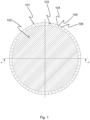
- Fig. 1 illustrates a foundation according to an embodiment of the invention for an offshore structure. The foundation is shown from above.
- the foundation comprises a cylindrical wall 101 and a top deck 102 that is attached to an upper end of the cylindrical wall 101.
- the cylindrical wall 101 and the top deck 102 define a downwardly open hollow space (not shown in fig. 1 ), i.e., a hollow space that is open at the bottom of the foundation.
- An offshore structure is meant to be attached on the top deck 102.
- the cylindrical wall 101 functions as a load-bearing element that transfers the load of the offshore structure into the ground, such as the seabed.
- the cylindrical wall 101 consists of wall sections 103, which are attached to one another so that they form a closed perimeter.
- Each wall section 103 comprises a first elongated hollow body 104 and a second elongated hollow body 105 that is arranged inside the first elongated hollow body 104.
- An upper end of the first elongated hollow body 104 is closed by an upper end member 106 that is provided with an opening through which an upper end of the second elongated hollow body 105 passes.
- a lower end of the first elongated hollow body 104 is closed by a lower end member (not shown in fig. 1 ) that is provided with an opening through which a lower end of the second elongated hollow body 105 passes.
- the upper end member 106 and the lower end member seal the space between the first elongated hollow body 104 and the second elongated hollow body 105.
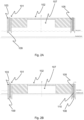
- Figs. 2A-2B illustrate the installation of the foundation of fig. 1 into the seabed.
- the foundation is shown as a cross sectional view taken along the line A-A of fig. 1 .
- the foundation is shown floating in water.
- the foundation is arranged in such a manner that its bottom is towards the seabed.
- the foundation has been set at a desired height relative to the sea level by controlling the amount of air inside the downwardly open hollow space 107.
- the foundation is lowered by removing air and water from the downwardly open hollow space 107 until the lower end of the cylindrical wall 101 comes into contact with the seabed and begins to penetrate into it.
- the soil under the wall sections 103 is removed by using bottom pumps 108 that are attached to the lower ends of the second elongated hollow bodies 105.
- the lower end member 109 has a conical portion that directs the soil towards the bottom pump 108.
- the soil is carried away through riser pipes 110, which are arranged inside the second elongated hollow bodies 105.
- riser pipes 110 which are arranged inside the second elongated hollow bodies 105.
Landscapes
- Engineering & Computer Science (AREA)
- Life Sciences & Earth Sciences (AREA)
- General Life Sciences & Earth Sciences (AREA)
- Mining & Mineral Resources (AREA)
- Paleontology (AREA)
- Civil Engineering (AREA)
- General Engineering & Computer Science (AREA)
- Structural Engineering (AREA)
- Foundations (AREA)
Claims (13)
- Fundament für eine Offshore-Struktur, umfassend:- eine Wand (101), die einen geschlossenen Umfang bildet und ein oberes und ein unteres Ende aufweist, und- ein Oberdeck (102), das am oberen Ende der Wand (101) angebracht ist, wobei das Oberdeck (102) und die Wand (101) einen nach unten offenen Hohlraum (107) begrenzen, dadurch gekennzeichnet, dass die Wand (101) eine Vielzahl von Wandabschnitten (103) umfasst, wobei jeder Wandabschnitt (103) einen ersten länglichen Hohlkörper (104) mit einem oberen und einem unteren Ende, wobei das untere Ende durch ein mit einer Öffnung versehenes Endelement (109) verschlossen ist, und einen zweiten länglichen Hohlkörper (105) mit einem oberen und einem unteren Ende umfasst, wobei der zweite längliche Hohlkörper (105) innerhalb des ersten länglichen Hohlkörpers (104) angeordnet ist, so dass das untere Ende des zweiten länglichen Hohlkörpers (105) durch die Öffnung verläuft und an dem Endelement (109) befestigt ist.
- Fundament nach Anspruch 1, dadurch gekennzeichnet, dass die Wand (101) eine zylindrische Wand (101) ist.
- Fundament nach Anspruch 1 oder 2, dadurch gekennzeichnet, dass das Fundament Mittel zum Übertragen von Flüssigkeit in den und aus dem nach unten offenen Hohlraum (107) aufweist.
- Fundament nach einem der vorhergehenden Ansprüche, dadurch gekennzeichnet, dass der Wandabschnitt (103) eine Bodenpumpe (108), die am unteren Ende des zweiten länglichen Hohlkörpers (105) angebracht ist, um Erde zu entfernen, und ein Steigrohr (110) umfasst, das innerhalb des zweiten länglichen Hohlkörpers (105) angeordnet ist, um die Erde zu befördern, wobei ein unteres Ende des Steigrohrs (110) an der Bodenpumpe (108) angebracht ist.
- Fundament nach Anspruch 4, dadurch gekennzeichnet, dass die Bodenpumpe (108) eine Schneideinheit zum Auflockern des Bodens aufweist.
- Fundament nach Anspruch 4 oder 5, dadurch gekennzeichnet, dass die Bodenpumpe (108) eine Wassersprüheinheit zum Verflüssigen des Bodens aufweist.
- Fundament nach einem der vorhergehenden Ansprüche, dadurch gekennzeichnet, dass das Fundament mehrere Luftkissen aufweist.
- Fundament nach einem der vorhergehenden Ansprüche, dadurch gekennzeichnet, dass der Wandabschnitt (103) eine Vielzahl von Außenstützen umfasst, die an einer Außenfläche des ersten länglichen Hohlkörpers (104) befestigt sind.
- Fundament nach einem der vorhergehenden Ansprüche, dadurch gekennzeichnet, dass der Wandabschnitt (103) eine Vielzahl von inneren Stützen umfasst, die zwischen einer Innenfläche des ersten länglichen Hohlkörpers (104) und einer Außenfläche des zweiten länglichen Hohlkörpers (105) angebracht sind.
- Fundament nach einem der vorhergehenden Ansprüche, dadurch gekennzeichnet, dass das Endelement (109) einen konischen Abschnitt aufweist.
- Fundament nach einem der vorhergehenden Ansprüche, dadurch gekennzeichnet, dass das Fundament Mittel zum Heizen und Kühlen der Wand (101) aufweist.
- Fundament nach einem der vorhergehenden Ansprüche, dadurch gekennzeichnet, dass das Fundament Mittel zum Vibrieren der Wand (101) aufweist.
- Verfahren zum Installieren eines Fundaments nach Anspruch 1, dadurch gekennzeichnet, dass das Verfahren Folgendes umfasst:- Anordnen des Fundaments, so dass es im Wasser schwimmt,- Schleppen des Fundaments zu einem Installationsort,- Entfernen von Flüssigkeit aus dem nach unten offenen Hohlraum (107),- Verwenden einer Vielzahl von Bodenpumpen (108), die an den unteren Enden der zweiten länglichen Hohlkörper (105) angebracht sind, um Erde zu entfernen, und- Verwenden einer Vielzahl von Steigrohren (110), die innerhalb der zweiten länglichen Hohlkörper (105) angeordnet sind, um die Erde zu transportieren.
Applications Claiming Priority (2)
| Application Number | Priority Date | Filing Date | Title |
|---|---|---|---|
| FI20215088 | 2021-01-27 | ||
| PCT/FI2022/050042 WO2022162274A1 (en) | 2021-01-27 | 2022-01-24 | Foundation for an offshore structure and method for installing a foundation |
Publications (3)
| Publication Number | Publication Date |
|---|---|
| EP4284980A1 EP4284980A1 (de) | 2023-12-06 |
| EP4284980B1 true EP4284980B1 (de) | 2024-11-13 |
| EP4284980C0 EP4284980C0 (de) | 2024-11-13 |
Family
ID=80123176
Family Applications (1)
| Application Number | Title | Priority Date | Filing Date |
|---|---|---|---|
| EP22701667.2A Active EP4284980B1 (de) | 2021-01-27 | 2022-01-24 | Fundament für ein offshore-bauwerk und verfahren zum installieren eines fundaments |
Country Status (6)
| Country | Link |
|---|---|
| EP (1) | EP4284980B1 (de) |
| KR (1) | KR20230133964A (de) |
| CN (1) | CN116806280A (de) |
| CA (1) | CA3204927A1 (de) |
| PL (1) | PL4284980T3 (de) |
| WO (1) | WO2022162274A1 (de) |
Family Cites Families (4)
| Publication number | Priority date | Publication date | Assignee | Title |
|---|---|---|---|---|
| GB628123A (en) * | 1946-08-20 | 1949-08-23 | Andre Larquetoux | Improvements in or relating to structural foundations |
| GB2264733B (en) * | 1992-03-03 | 1995-10-18 | British Gas Plc | Apparatus intended to be buried in ground beneath water |
| CN106759419A (zh) * | 2017-03-16 | 2017-05-31 | 天津大学前沿技术研究院有限公司 | 一种环形分区水力破土开槽装置 |
| CN108842798B (zh) * | 2018-06-27 | 2021-10-19 | 上海城建市政工程(集团)有限公司 | 一种预制后浇筑式沉井的静压下沉施工方法 |
-
2022
- 2022-01-24 KR KR1020237025386A patent/KR20230133964A/ko active Pending
- 2022-01-24 CA CA3204927A patent/CA3204927A1/en active Pending
- 2022-01-24 EP EP22701667.2A patent/EP4284980B1/de active Active
- 2022-01-24 WO PCT/FI2022/050042 patent/WO2022162274A1/en not_active Ceased
- 2022-01-24 CN CN202280011967.2A patent/CN116806280A/zh active Pending
- 2022-01-24 PL PL22701667.2T patent/PL4284980T3/pl unknown
Also Published As
| Publication number | Publication date |
|---|---|
| CN116806280A (zh) | 2023-09-26 |
| PL4284980T3 (pl) | 2025-06-09 |
| EP4284980A1 (de) | 2023-12-06 |
| WO2022162274A1 (en) | 2022-08-04 |
| US20240084542A1 (en) | 2024-03-14 |
| KR20230133964A (ko) | 2023-09-19 |
| CA3204927A1 (en) | 2022-08-04 |
| EP4284980C0 (de) | 2024-11-13 |
Similar Documents
| Publication | Publication Date | Title |
|---|---|---|
| EP2310670B1 (de) | Stützstruktur zur verwendung in der offshore-windparkindustrie | |
| US4761096A (en) | Universal footing with jetting system | |
| JP2002529630A (ja) | 沖合水中工事用ケーソン | |
| CA1212250A (en) | Modular arctic structures system | |
| BE1020365A4 (nl) | Inrichting en werkwijze voor het boren van schachten in een uit rots, klei en/of aanverwante materialen bestaande ondergrond. | |
| US4693637A (en) | Gravity type oceanic structure and its stable installation | |
| US6203248B1 (en) | Sliding-resistant bottom-founded offshore structures | |
| EP1268947B1 (de) | Verfahren zur herstellung eines fundaments für offshore-installationen im meeresboden sowie entsprechendes fundament | |
| WO2003080939A1 (en) | Foundation structure | |
| EP4284980B1 (de) | Fundament für ein offshore-bauwerk und verfahren zum installieren eines fundaments | |
| WO2024058672A1 (en) | Pile structure for an offshore wind turbine and methods of installing the same | |
| WO2010143976A2 (en) | A foundation, a method of manufacturing the foundation, and a method of installing the foundation on a seabed | |
| US12497747B2 (en) | Foundation for an offshore structure and method for installing a foundation | |
| US4711601A (en) | Method of installing offshore constructions | |
| JP3603193B2 (ja) | 水中基礎の構築方法 | |
| NL2028088B1 (en) | Concrete connector body for an offshore wind turbine. | |
| US12157983B2 (en) | Pile and method for installing a pile | |
| CN104762942A (zh) | 水上建筑海洋固定平台软土地基海底固定安装施工法 | |
| KR20250032133A (ko) | 초기 관입수단을 갖는 석션파일앵커 | |
| JP2023056370A (ja) | 基礎構造および基礎構造の構築方法 | |
| EP4386144B1 (de) | Verfahren und zugehörige vorrichtung | |
| JP2023139586A (ja) | 水底設置用筒状体の補強構造及び補強方法 | |
| NL1044632B1 (nl) | Inrichting voor het installeren van buiswanden op zee geschikt voor het onderbrengen van industriële processen waarbij een havenruimte ontstaat. | |
| EA043347B1 (ru) | Свая и способ установки сваи | |
| JP3054731B2 (ja) | 構造物基礎の支持力増強装置および支持力増強方法 |
Legal Events
| Date | Code | Title | Description |
|---|---|---|---|
| STAA | Information on the status of an ep patent application or granted ep patent |
Free format text: STATUS: UNKNOWN |
|
| STAA | Information on the status of an ep patent application or granted ep patent |
Free format text: STATUS: THE INTERNATIONAL PUBLICATION HAS BEEN MADE |
|
| PUAI | Public reference made under article 153(3) epc to a published international application that has entered the european phase |
Free format text: ORIGINAL CODE: 0009012 |
|
| STAA | Information on the status of an ep patent application or granted ep patent |
Free format text: STATUS: REQUEST FOR EXAMINATION WAS MADE |
|
| 17P | Request for examination filed |
Effective date: 20230822 |
|
| AK | Designated contracting states |
Kind code of ref document: A1 Designated state(s): AL AT BE BG CH CY CZ DE DK EE ES FI FR GB GR HR HU IE IS IT LI LT LU LV MC MK MT NL NO PL PT RO RS SE SI SK SM TR |
|
| DAV | Request for validation of the european patent (deleted) | ||
| DAX | Request for extension of the european patent (deleted) | ||
| GRAP | Despatch of communication of intention to grant a patent |
Free format text: ORIGINAL CODE: EPIDOSNIGR1 |
|
| STAA | Information on the status of an ep patent application or granted ep patent |
Free format text: STATUS: GRANT OF PATENT IS INTENDED |
|
| RIC1 | Information provided on ipc code assigned before grant |
Ipc: E02D 27/42 20060101ALI20240710BHEP Ipc: E02D 23/02 20060101ALI20240710BHEP Ipc: E02D 27/52 20060101ALI20240710BHEP Ipc: E02D 23/08 20060101ALI20240710BHEP Ipc: E02D 15/08 20060101AFI20240710BHEP |
|
| INTG | Intention to grant announced |
Effective date: 20240726 |
|
| GRAS | Grant fee paid |
Free format text: ORIGINAL CODE: EPIDOSNIGR3 |
|
| GRAA | (expected) grant |
Free format text: ORIGINAL CODE: 0009210 |
|
| STAA | Information on the status of an ep patent application or granted ep patent |
Free format text: STATUS: THE PATENT HAS BEEN GRANTED |
|
| AK | Designated contracting states |
Kind code of ref document: B1 Designated state(s): AL AT BE BG CH CY CZ DE DK EE ES FI FR GB GR HR HU IE IS IT LI LT LU LV MC MK MT NL NO PL PT RO RS SE SI SK SM TR |
|
| REG | Reference to a national code |
Ref country code: GB Ref legal event code: FG4D |
|
| REG | Reference to a national code |
Ref country code: CH Ref legal event code: EP |
|
| REG | Reference to a national code |
Ref country code: IE Ref legal event code: FG4D |
|
| REG | Reference to a national code |
Ref country code: DE Ref legal event code: R096 Ref document number: 602022007711 Country of ref document: DE |
|
| U01 | Request for unitary effect filed |
Effective date: 20241211 |
|
| U07 | Unitary effect registered |
Designated state(s): AT BE BG DE DK EE FI FR IT LT LU LV MT NL PT RO SE SI Effective date: 20241219 |
|
| PG25 | Lapsed in a contracting state [announced via postgrant information from national office to epo] |
Ref country code: HR Free format text: LAPSE BECAUSE OF FAILURE TO SUBMIT A TRANSLATION OF THE DESCRIPTION OR TO PAY THE FEE WITHIN THE PRESCRIBED TIME-LIMIT Effective date: 20241113 Ref country code: IS Free format text: LAPSE BECAUSE OF FAILURE TO SUBMIT A TRANSLATION OF THE DESCRIPTION OR TO PAY THE FEE WITHIN THE PRESCRIBED TIME-LIMIT Effective date: 20250313 |
|
| PG25 | Lapsed in a contracting state [announced via postgrant information from national office to epo] |
Ref country code: ES Free format text: LAPSE BECAUSE OF FAILURE TO SUBMIT A TRANSLATION OF THE DESCRIPTION OR TO PAY THE FEE WITHIN THE PRESCRIBED TIME-LIMIT Effective date: 20241113 |
|
| PG25 | Lapsed in a contracting state [announced via postgrant information from national office to epo] |
Ref country code: NO Free format text: LAPSE BECAUSE OF FAILURE TO SUBMIT A TRANSLATION OF THE DESCRIPTION OR TO PAY THE FEE WITHIN THE PRESCRIBED TIME-LIMIT Effective date: 20250213 |
|
| U20 | Renewal fee for the european patent with unitary effect paid |
Year of fee payment: 4 Effective date: 20250317 |
|
| PG25 | Lapsed in a contracting state [announced via postgrant information from national office to epo] |
Ref country code: GR Free format text: LAPSE BECAUSE OF FAILURE TO SUBMIT A TRANSLATION OF THE DESCRIPTION OR TO PAY THE FEE WITHIN THE PRESCRIBED TIME-LIMIT Effective date: 20250214 |
|
| PG25 | Lapsed in a contracting state [announced via postgrant information from national office to epo] |
Ref country code: RS Free format text: LAPSE BECAUSE OF FAILURE TO SUBMIT A TRANSLATION OF THE DESCRIPTION OR TO PAY THE FEE WITHIN THE PRESCRIBED TIME-LIMIT Effective date: 20250213 |
|
| PGFP | Annual fee paid to national office [announced via postgrant information from national office to epo] |
Ref country code: TR Payment date: 20250124 Year of fee payment: 4 |
|
| PG25 | Lapsed in a contracting state [announced via postgrant information from national office to epo] |
Ref country code: SM Free format text: LAPSE BECAUSE OF FAILURE TO SUBMIT A TRANSLATION OF THE DESCRIPTION OR TO PAY THE FEE WITHIN THE PRESCRIBED TIME-LIMIT Effective date: 20241113 |
|
| PGFP | Annual fee paid to national office [announced via postgrant information from national office to epo] |
Ref country code: PL Payment date: 20250110 Year of fee payment: 4 |
|
| PG25 | Lapsed in a contracting state [announced via postgrant information from national office to epo] |
Ref country code: SK Free format text: LAPSE BECAUSE OF FAILURE TO SUBMIT A TRANSLATION OF THE DESCRIPTION OR TO PAY THE FEE WITHIN THE PRESCRIBED TIME-LIMIT Effective date: 20241113 |
|
| PG25 | Lapsed in a contracting state [announced via postgrant information from national office to epo] |
Ref country code: CZ Free format text: LAPSE BECAUSE OF FAILURE TO SUBMIT A TRANSLATION OF THE DESCRIPTION OR TO PAY THE FEE WITHIN THE PRESCRIBED TIME-LIMIT Effective date: 20241113 |
|
| REG | Reference to a national code |
Ref country code: CH Ref legal event code: PL |
|
| PG25 | Lapsed in a contracting state [announced via postgrant information from national office to epo] |
Ref country code: MC Free format text: LAPSE BECAUSE OF FAILURE TO SUBMIT A TRANSLATION OF THE DESCRIPTION OR TO PAY THE FEE WITHIN THE PRESCRIBED TIME-LIMIT Effective date: 20241113 |
|
| PLBE | No opposition filed within time limit |
Free format text: ORIGINAL CODE: 0009261 |
|
| STAA | Information on the status of an ep patent application or granted ep patent |
Free format text: STATUS: NO OPPOSITION FILED WITHIN TIME LIMIT |
|
| PG25 | Lapsed in a contracting state [announced via postgrant information from national office to epo] |
Ref country code: CH Free format text: LAPSE BECAUSE OF NON-PAYMENT OF DUE FEES Effective date: 20250131 |
|
| 26N | No opposition filed |
Effective date: 20250814 |