EP4002540B1 - Pressing jig for removing gas trap and method for manufacturing secondary battery using same - Google Patents
Pressing jig for removing gas trap and method for manufacturing secondary battery using same Download PDFInfo
- Publication number
- EP4002540B1 EP4002540B1 EP21738846.1A EP21738846A EP4002540B1 EP 4002540 B1 EP4002540 B1 EP 4002540B1 EP 21738846 A EP21738846 A EP 21738846A EP 4002540 B1 EP4002540 B1 EP 4002540B1
- Authority
- EP
- European Patent Office
- Prior art keywords
- battery cell
- subplates
- pressing
- pressing jig
- press
- Prior art date
- Legal status (The legal status is an assumption and is not a legal conclusion. Google has not performed a legal analysis and makes no representation as to the accuracy of the status listed.)
- Active
Links
Images


Classifications
-
- H—ELECTRICITY
- H01—ELECTRIC ELEMENTS
- H01M—PROCESSES OR MEANS, e.g. BATTERIES, FOR THE DIRECT CONVERSION OF CHEMICAL ENERGY INTO ELECTRICAL ENERGY
- H01M10/00—Secondary cells; Manufacture thereof
- H01M10/42—Methods or arrangements for servicing or maintenance of secondary cells or secondary half-cells
- H01M10/44—Methods for charging or discharging
- H01M10/446—Initial charging measures
-
- H—ELECTRICITY
- H01—ELECTRIC ELEMENTS
- H01M—PROCESSES OR MEANS, e.g. BATTERIES, FOR THE DIRECT CONVERSION OF CHEMICAL ENERGY INTO ELECTRICAL ENERGY
- H01M10/00—Secondary cells; Manufacture thereof
- H01M10/04—Construction or manufacture in general
- H01M10/0481—Compression means other than compression means for stacks of electrodes and separators
-
- H—ELECTRICITY
- H01—ELECTRIC ELEMENTS
- H01M—PROCESSES OR MEANS, e.g. BATTERIES, FOR THE DIRECT CONVERSION OF CHEMICAL ENERGY INTO ELECTRICAL ENERGY
- H01M10/00—Secondary cells; Manufacture thereof
- H01M10/04—Construction or manufacture in general
- H01M10/049—Processes for forming or storing electrodes in the battery container
-
- H—ELECTRICITY
- H01—ELECTRIC ELEMENTS
- H01M—PROCESSES OR MEANS, e.g. BATTERIES, FOR THE DIRECT CONVERSION OF CHEMICAL ENERGY INTO ELECTRICAL ENERGY
- H01M10/00—Secondary cells; Manufacture thereof
- H01M10/05—Accumulators with non-aqueous electrolyte
- H01M10/058—Construction or manufacture
-
- H—ELECTRICITY
- H01—ELECTRIC ELEMENTS
- H01M—PROCESSES OR MEANS, e.g. BATTERIES, FOR THE DIRECT CONVERSION OF CHEMICAL ENERGY INTO ELECTRICAL ENERGY
- H01M10/00—Secondary cells; Manufacture thereof
- H01M10/42—Methods or arrangements for servicing or maintenance of secondary cells or secondary half-cells
- H01M10/52—Removing gases inside the secondary cell, e.g. by absorption
-
- H—ELECTRICITY
- H01—ELECTRIC ELEMENTS
- H01M—PROCESSES OR MEANS, e.g. BATTERIES, FOR THE DIRECT CONVERSION OF CHEMICAL ENERGY INTO ELECTRICAL ENERGY
- H01M10/00—Secondary cells; Manufacture thereof
- H01M10/60—Heating or cooling; Temperature control
- H01M10/61—Types of temperature control
- H01M10/615—Heating or keeping warm
-
- H—ELECTRICITY
- H01—ELECTRIC ELEMENTS
- H01M—PROCESSES OR MEANS, e.g. BATTERIES, FOR THE DIRECT CONVERSION OF CHEMICAL ENERGY INTO ELECTRICAL ENERGY
- H01M4/00—Electrodes
- H01M4/02—Electrodes composed of, or comprising, active material
- H01M4/04—Processes of manufacture in general
- H01M4/0438—Processes of manufacture in general by electrochemical processing
- H01M4/044—Activating, forming or electrochemical attack of the supporting material
- H01M4/0445—Forming after manufacture of the electrode, e.g. first charge, cycling
- H01M4/0447—Forming after manufacture of the electrode, e.g. first charge, cycling of complete cells or cells stacks
-
- H—ELECTRICITY
- H01—ELECTRIC ELEMENTS
- H01M—PROCESSES OR MEANS, e.g. BATTERIES, FOR THE DIRECT CONVERSION OF CHEMICAL ENERGY INTO ELECTRICAL ENERGY
- H01M50/00—Constructional details or processes of manufacture of the non-active parts of electrochemical cells other than fuel cells, e.g. hybrid cells
- H01M50/30—Arrangements for facilitating escape of gases
- H01M50/317—Re-sealable arrangements
-
- H—ELECTRICITY
- H01—ELECTRIC ELEMENTS
- H01M—PROCESSES OR MEANS, e.g. BATTERIES, FOR THE DIRECT CONVERSION OF CHEMICAL ENERGY INTO ELECTRICAL ENERGY
- H01M50/00—Constructional details or processes of manufacture of the non-active parts of electrochemical cells other than fuel cells, e.g. hybrid cells
- H01M50/30—Arrangements for facilitating escape of gases
- H01M50/394—Gas-pervious parts or elements
-
- H—ELECTRICITY
- H01—ELECTRIC ELEMENTS
- H01M—PROCESSES OR MEANS, e.g. BATTERIES, FOR THE DIRECT CONVERSION OF CHEMICAL ENERGY INTO ELECTRICAL ENERGY
- H01M10/00—Secondary cells; Manufacture thereof
- H01M10/05—Accumulators with non-aqueous electrolyte
- H01M10/052—Li-accumulators
- H01M10/0525—Rocking-chair batteries, i.e. batteries with lithium insertion or intercalation in both electrodes; Lithium-ion batteries
-
- Y—GENERAL TAGGING OF NEW TECHNOLOGICAL DEVELOPMENTS; GENERAL TAGGING OF CROSS-SECTIONAL TECHNOLOGIES SPANNING OVER SEVERAL SECTIONS OF THE IPC; TECHNICAL SUBJECTS COVERED BY FORMER USPC CROSS-REFERENCE ART COLLECTIONS [XRACs] AND DIGESTS
- Y02—TECHNOLOGIES OR APPLICATIONS FOR MITIGATION OR ADAPTATION AGAINST CLIMATE CHANGE
- Y02E—REDUCTION OF GREENHOUSE GAS [GHG] EMISSIONS, RELATED TO ENERGY GENERATION, TRANSMISSION OR DISTRIBUTION
- Y02E60/00—Enabling technologies; Technologies with a potential or indirect contribution to GHG emissions mitigation
- Y02E60/10—Energy storage using batteries
-
- Y—GENERAL TAGGING OF NEW TECHNOLOGICAL DEVELOPMENTS; GENERAL TAGGING OF CROSS-SECTIONAL TECHNOLOGIES SPANNING OVER SEVERAL SECTIONS OF THE IPC; TECHNICAL SUBJECTS COVERED BY FORMER USPC CROSS-REFERENCE ART COLLECTIONS [XRACs] AND DIGESTS
- Y02—TECHNOLOGIES OR APPLICATIONS FOR MITIGATION OR ADAPTATION AGAINST CLIMATE CHANGE
- Y02P—CLIMATE CHANGE MITIGATION TECHNOLOGIES IN THE PRODUCTION OR PROCESSING OF GOODS
- Y02P70/00—Climate change mitigation technologies in the production process for final industrial or consumer products
- Y02P70/50—Manufacturing or production processes characterised by the final manufactured product
Definitions
- the present invention relates to a pressing jig for removing gas generated during an activation process, and a method for manufacturing a secondary battery using the same.
- lithium secondary batteries such as lithium ion batteries and lithium ion polymer batteries having advantages such as high energy density, discharge voltage, and output stability.
- secondary batteries are classified according to the structure of the electrode assembly having a positive electrode/separator/negative electrode structure.
- Representative examples thereof include a jelly-roll (wound) type electrode assembly in which long sheet type positive electrodes and negative electrodes are wound with a separator interposed therebetween, a stacked type electrode assembly in which a plurality of positive and negative electrodes cut in a predetermined size unit are sequentially stacked with a separator interposed therebetween, and a stacked/folded type electrode assembly in which bi-cells or full cells, in which positive and negative electrodes of a predetermined unit are stacked with a separator interposed therebetween, are wound.
- a pouch type battery having a stacked type or stacked/folded type electrode assembly embedded in a pouch-shaped battery case of an aluminum laminate sheet has attracted a lot of attention due to its low manufacturing cost and small weight, and the amount used thereof is gradually increasing.
- activated battery cells are fixed at a die and are simply pressed from the upper portion to remove gas.
- gas inside the battery cell corresponds to a fluid, and thus when there is pressure from the outer side, gas is dispersed in all directions without directionality. At this time, some of the gas is collected in the surplus portion for collecting gas, which is positioned at one side of the sealing unit of the battery cell, and is then removed. Some of the gas remains in the battery cell. This is called a gas trap, and such a gas trap has a danger of generating lithium precipitation during the following charging/discharging process.
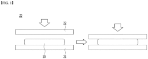
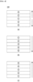
- FIG. 1 shows a conventional pressing jig.
- the existing pressing jig 20 fixes a battery cell 10 on a plate-shaped die 21, and a plate-shaped upper plate 22 presses the battery cell from the upper portion.
- gas is dispersed without directionality during the pressing process, and a gas trap, in which some gas remains inside the battery cell, occurs.
- KR 1650858 A discloses a degassing apparatus including a pressing jig having an arc shape that is downward-protruding on a vertical cross section.
- the pressing jig has an arc shape on a vertical cross-section, so that the pressed surface is not flat. As such, when the battery cell is pressed, it is difficult to apply constant pressure to the pressed portion. Further, the pressurization is only performed sequentially from the center toward the external side, and thus there are not many options of the pressing directions.
- KR 2012 0009661 A describes a manufacturing method of a pouch type lithium secondary battery comprising a step of connecting a dead space for discharge gas, which is generated from the inside of a battery cell through formation, to the battery cell, and a step of applying a pressure of 5 to 15 kg/cm 2 to the battery cell from outside during the formation of the battery cell.
- an object of the present invention is to provide a pressing jig for effectively removing internal gas generated during an activation process and preventing a gas trap.
- the present invention for achieving the above object is a pressing jig having a pair of plates facing each other for pressing a battery cell after interposing the battery cell between the pair of plates to remove gas generated in an activation process of the battery cell, in which at least one of the pair of plates is provided as a combination of n separate subplates, the subplates each independently press the battery cell, and n is equal to or greater than 3.
- the pair of plates comprise: a lower plate configured to support the battery cell at a lower portion of the battery cell; and an upper plate configured to press the battery cell at an upper portion of the battery cell, and the at least one of the pair of plates is only the upper plate, and the upper plate sequentially presses a top surface of the battery cell.
- the pair of plates include: a lower plate configured to press the battery cell from a lower portion of the battery cell; and an upper plate configured to press the battery cell at an upper portion of the battery cell, and the at least one of the pair of plates is both the upper plate and the lower plate, and the upper plate and the lower plate sequentially press both surfaces of the battery cell.
- the subplates sequentially press the battery cell in one direction selected from a radial direction, a left and right direction, a left direction, a right direction, a vertical direction, an upward direction and a downward direction.
- the lower plate includes a heating unit.
- the subplates are consecutively set.
- At least one of the plurality of subplates has a heating unit.
- each of the subplates has a same volume, and the subplates form one upper plate.
- each of the subplates has different volumes, and the subplates form one upper plate.
- a method for manufacturing a secondary battery of the present invention includes: an activation step(S 100) of activating the battery cell by charging and discharging the battery cell; and a pressing step(S200) of collecting gas generated during the activation step in a gas pocket by pressing the battery cell, wherein in the pressing step, the subplates sequentially press the battery cell in one direction selected from a radial direction, a left and right direction, a left direction, a right direction, a vertical direction, an upward direction and a downward direction.
- the pressing step (S200) includes: a process of mounting the battery cell on the pressing jig; a first pressing process of pressing the battery cell by some of the subplates; and a second pressing process of sequentially pressing the battery cell by remaining subplates.
- the subplates sequentially press one surface of the battery cell.
- the subplates sequentially press both surfaces of the battery cell.
- the method for manufacturing the secondary battery of the present invention further includes: a perforation step(S300) of perforating a through hole connected to an inside of a battery case to discharge the gas collected in the gas pocket to an outside; and a sealing step(S400) of sealing, by heat fusion, after discharging t internal gas through the through hole formed in the perforation step.
- n separate subplates are assembled on the pressing surface of the pressing jig to thereby form one plate, thereby inducing sequential pressurization to the secondary battery and smooth discharge of gas.
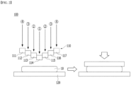
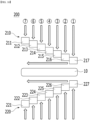
- FIG. 2 is a pressing jig according to an embodiment of the present invention.
- the pressing jig 100 is a pressing jig for interposing a battery cell between one pair of facing plates and pressing the battery cell in order to remove gas generated during the activation process of the battery cell.
- At least one of the pair of plates 110 and 120 has a structure in which n ( n ⁇ 3) separate subplates 111, 112, 113, 114, 115, 116 and 117 are assembled and form one plate 110, and each of the subplates independently presses the battery cell.
- n is an integer of 3 or more, and specifically, it is an integer ranging from 3 to 20, 3 to 10 or 3 to 5.
- the one pair of plates include: a lower plate 120 configured to support a battery cell on a lower portion of the battery cell; and an upper plate 110 configured to press the battery cell from an upper portion of the battery cell.
- a lower plate 120 configured to support a battery cell on a lower portion of the battery cell
- an upper plate 110 configured to press the battery cell from an upper portion of the battery cell.
- only the upper plate is formed by combination of subplates 111, 112, 113, 114, 115, 116 and 117 and has a structure of sequentially pressing only the top surface of the battery cell.
- the pressing jig according to the present invention can partially or sequential press battery cells by applying a plate of a structure in which separate subplates are assembled.
- the internal gas may be more effectively discharged, and generation of the gas trap may be effectively prevented.
- the subplates are consecutively set.
- the battery cell can be sequentially pressed by forming one plate by consecutive assembling.
- the first subplate 114 in the center first presses the battery cell.
- the second subplates 113 and 115 adjacent to the first subplate 114 secondly press the battery cell, the third subplates 112 and 116 thirdly press the battery cell, and then the fourth subplates 111 and 117 at the outermost portions finally press the battery cell.
- the gas inside the battery cell comes to have a mobility from the center in the left direction and from the center in the right direction.
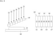
- FIG. 3 is a diagram illustrating a pressing jig according to another embodiment.
- the subplates 112, 113, 114, 115, 116 and 117 sequentially press the battery cell from the subplate 111 positioned at the leftmost side in the right direction. Hence, the gas inside the battery cell moves from the left to the right with directionality.
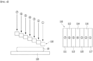
- FIG. 4 is a diagram illustrating a pressing jig according to an embodiment of the present invention.
- the subplates 112, 113, 114, 115, 116 and 117 sequentially press battery cell from the subplate 117 positioned at the rightmost side in the left direction. Hence, the gas inside the battery cell moves from the right to the left with directionality.
- the volumes of the subplates are the same.
- the same volume means that the widths, the lengths and the thicknesses of the subplates are the same, and thus the shapes and the volumes of the subplates are the same.
- the upper plate consisting of the subplates of the same volume is illustrated in the embodiment, but it is not limited thereto. It can be appropriately selected whether the shapes and volumes of respective subplates are set to be the same according to the structural features and needs of the battery cell.
- FIG. 5 shows a plate of a structure in which subplates are assembled according to an embodiment of the present invention.
- the first subplate 111 in the center is plate-shaped, and the second subplate 112 to the fourth subplate 114 have a " ⁇ " shape having a rectangular through hole in the center of a point of having a predetermined separation distance from the outer peripheral surface.
- the subplate has a structure in which first to fourth subplates sequentially press the battery cell, and the gas inside the battery cell moves in a rectangular shape with directionality by the sequential pressurization.
- the subplates constituting the upper plate of the present invention sequentially press the battery cell in one direction selected from a radial direction, a left and right direction, a left direction, a right direction, a vertical direction, an upward direction and a downward direction.
- FIGS. 8 to 10 illustrate a pressing jig 200 according to another embodiment of the present invention.
- the one pair of plates include: a lower plate 220 configured to press a battery cell on a lower portion of a battery cell; and an upper plate 210 configured to press the battery cell from an upper portion of the battery cell.
- both the upper plate and the lower plate are formed by combination of subplates 211, 212, 213, 214, 215, 216, 217, 221, 222, 223, 224, 225, 226 and 227 and have a structure of sequentially pressing both surfaces of the battery cell.
- the subplates 214 and 224 in the center first press the battery cell. Thereafter, subplates 213, 215, 223 and 225 adjacent to the subplates in the center press the battery cell. Thereafter, subplates 212, 216, 222 and 226 adjacent to the subplates 213, 215, 223 and 225 press the battery cell. In this way, the battery cell is sequentially pressed. Accordingly, the inner gas is moved from the center in the left direction or the right direction. Further, as in FIG. 9 , the subplates may sequentially press the battery cell from the left side in the right direction, and as in FIG. 10 , the subplates may sequentially press the battery cell from the right side in the left direction.
- the lower plate of the present invention may include a heating unit.
- the heating unit is a heater for applying heat to the battery cell.
- the heater may heat the battery cell to 30 to 100°C, and preferably to 40 to 80°C.
- the heating temperature is less than 30°C, kinetic energy transmitted to gas is not large. Hence, it is difficult to expect significant effects in removing gas inside the battery cell, and when the heating temperature is greater than 100°C, the electrolyte solution in the battery cell may be decomposed or the battery case may be deformed.
- the lower plate of the present invention can embed an exciter in the battery cell.
- the exciter has the advantage of delivering kinetic energy to the gas present in the battery cell, to thereby more effectively capture and remove the inner gas.
- one or more of the subplates constituting the upper plate may include a heating unit.
- the battery cell can be pressed from both sides by including a heating unit in the upper plate in addition to the lower plate. As such, kinetic energy may be further transmitted to the internal gas in the battery cell, by which collection and removal of gas may be more effectively performed.
- an elastic material may be added to at least a portion of the subplates, and specifically, an elastic material may be added to a portion in contact with at least a battery cell in the outer surface of the subplate. Excessive force is applied to a portion where the subplate contacts the battery cell while the subplates press the battery cell, and in some cases, the battery case may be broken. Therefore, it is desirable to distribute the force during contact of the subplate and the battery cell, and add an elastic material to the outer surface of the subplate to protect the battery case.
- the elastic material may be at least one selected from the group consisting of, for example, polystyrene, polyurethane, silicon, epoxy and rubber resin, and may be a foaming material in another example.
- a method for manufacturing a secondary battery according to the present invention includes: an activation step (S100) of activating the battery cell by charging and discharging the battery cell; and a pressing step (S200) of collecting gas generated during the activation step by pressing the battery cell, in a gas pocket, wherein in the pressing step (S200), the subplates sequentially press the battery cell in one direction selected from a radial direction, a left and right direction, a left direction, a right direction, a vertical direction, an upward direction and a downward direction.
- the activation step S100 is as follows. First, an electrode assembly is accommodated in a battery case, and electrolyte solution is injected. Thereafter, a solid electrolyte interface (SEI) layer is formed through electrochemical reaction between the electrode active material and the electrolyte solution by charging and discharging up to a predetermined SOC, to thereby activate the battery cell.
- SEI solid electrolyte interface
- the battery cell in order to remove internal gas generated by electrochemical reaction of electrode active materials and electrolyte solution during the activation step, the battery cell is sequentially pressed, and the gas inside the battery cell is collected into a gas pocket.
- the internal gas is moved with directionality, thereby preventing a gas trap.
- the pressing step (S200) includes: a process of mounting the battery cell on the pressing jig; a first pressing process of pressing the battery cell by some of the subplates; and a second pressing process of sequentially pressing the battery cell by remaining subplates.
- subplates may sequentially press only one surface of the battery cell as in FIG. 2 , and both surfaces of the battery cell may be sequentially pressed in as FIG. 8 .
- subplates have a structure of horizontally or vertically dividing one plate.
- FIG. 6(a) may be described as follows. First, the third subplate 113 in the center first presses the battery cell. Thereafter, the second subplate 112 and the fourth subplate 114 adjacent to the third subplate secondly press the battery cell. Finally, the first subplate 111 and the fifth subplate 115 at the outermost portion press the battery cell so that the gas in the battery cell may have directionality of moving in the upper direction and the lower direction.
- FIG. 6(b) shows an example that subplates sequentially press a battery cell from the upper portion in the lower direction
- FIG. 6(c) shows an example that subplates sequentially press a battery cell from the lower portion in the upper direction.
- FIG. 7 shows an example in which one plate has horizontally divided subplates.
- FIG. 7(a) shows an example where subplates sequentially press a battery cell from the center in left and right directions.
- FIG. 7(b) shows an example where subplates sequentially press the battery cell from the left in the right direction.
- FIG. 7(c) shows an example where subplates sequentially press the battery cell from the right in the left direction.
- the plate constituting of the pressing jig of the present invention is modularized by a plurality of subplates.
- the battery cell when performing pressurization for gas removal, the battery cell may be sequentially pressed in one of vertical direction, upper direction, lower direction, horizontal direction, left direction, right direction and radial direction.
- the method for manufacturing the secondary battery of the present invention further includes: a perforation step (S300) of perforating a through hole connected to an inside of a battery case to discharge the gas collected in the gas pocket to an outside; and a sealing step (S400) of sealing by heat fusion after discharging internal gas through the through hole formed in the perforation step.
- the battery cell may be a pouch-type battery cell where an electrode assembly and electrolyte solution are contained in the battery case of a laminate sheet including a resin layer and a metal layer.
- the laminate sheet may be an aluminum laminate sheet.
- a resin outer layer having an excellent durability may be added to one surface (outer surface) of the metal blocking layer, and a heat melting resin sealant layer may be added to the other surface (inner surface) of the metal blocking layer.
- the resin outer layer should have excellent resistance from the external environment, it is necessary to have a tensile strength and weather resistance of a predetermined level or more.
- PET polyethylene terephthalate
- stretched nylon film may be used as the polymer resin of the resin outer layer.
- the metal blocking layer may be made of aluminum so that the metal blocking layer may perform the function of improving the strength of the battery case in addition to the function of preventing an inflow or leakage of foreign materials such as gas and moisture.
- a polyolefin resin which has thermal adhesion, a low hygroscopicity, and is not expanded or eroded by the electrolyte solution, may be preferably used as the polymer resin of the resin sealant layer. More specifically, non-stretched polypropylene (CPP) may be used.
- CPP non-stretched polypropylene
- polyolefin resin such as polypropylene, etc.
- an adhesive layer may be further added between the metal layer and the resin sealant layer to thereby improve the adhesive force and blocking characteristics.
- the material of the adhesive layer may include, for example, a urethane material, an acryl material, a composition containing a thermoplastic elastomer, but not limited thereto.
- n separate subplates are assembled on the pressing surface of the pressing jig to thereby form one plate, thereby inducing sequential pressurization to the secondary battery and smooth discharge of gas.
Landscapes
- Chemical & Material Sciences (AREA)
- Chemical Kinetics & Catalysis (AREA)
- Electrochemistry (AREA)
- General Chemical & Material Sciences (AREA)
- Engineering & Computer Science (AREA)
- Manufacturing & Machinery (AREA)
- Secondary Cells (AREA)
- Cell Separators (AREA)
Applications Claiming Priority (2)
| Application Number | Priority Date | Filing Date | Title |
|---|---|---|---|
| KR1020200003780A KR102798481B1 (ko) | 2020-01-10 | 2020-01-10 | 가스 트랩 제거를 위한 가압 지그 및 이를 이용한 이차전지의 제조방법 |
| PCT/KR2021/000228 WO2021141427A1 (ko) | 2020-01-10 | 2021-01-08 | 가스 트랩 제거를 위한 가압 지그 및 이를 이용한 이차전지의 제조방법 |
Publications (3)
| Publication Number | Publication Date |
|---|---|
| EP4002540A1 EP4002540A1 (en) | 2022-05-25 |
| EP4002540A4 EP4002540A4 (en) | 2023-02-22 |
| EP4002540B1 true EP4002540B1 (en) | 2025-05-07 |
Family
ID=76788823
Family Applications (1)
| Application Number | Title | Priority Date | Filing Date |
|---|---|---|---|
| EP21738846.1A Active EP4002540B1 (en) | 2020-01-10 | 2021-01-08 | Pressing jig for removing gas trap and method for manufacturing secondary battery using same |
Country Status (9)
| Country | Link |
|---|---|
| US (1) | US11949062B2 (pl) |
| EP (1) | EP4002540B1 (pl) |
| JP (1) | JP7331306B2 (pl) |
| KR (1) | KR102798481B1 (pl) |
| CN (1) | CN114287080B (pl) |
| ES (1) | ES3031517T3 (pl) |
| HU (1) | HUE071683T2 (pl) |
| PL (1) | PL4002540T3 (pl) |
| WO (1) | WO2021141427A1 (pl) |
Families Citing this family (10)
| Publication number | Priority date | Publication date | Assignee | Title |
|---|---|---|---|---|
| KR102872034B1 (ko) * | 2020-10-23 | 2025-10-15 | 주식회사 엘지에너지솔루션 | 가압 패드를 포함하는 전지 셀의 가압 지그 및 이를 이용한 전지 셀의 디가싱 방법 |
| KR102640466B1 (ko) * | 2021-09-10 | 2024-02-27 | 주식회사 엘지에너지솔루션 | 이차전지의 활성화 방법 |
| KR102886236B1 (ko) * | 2021-09-28 | 2025-11-14 | 주식회사 엘지에너지솔루션 | 전지셀 가압장치 |
| KR102766712B1 (ko) * | 2021-10-08 | 2025-02-13 | 주식회사 테라온 | 이차전지 디개싱용 트레이 히터 |
| KR102819201B1 (ko) * | 2021-11-04 | 2025-06-11 | 주식회사 엘지에너지솔루션 | 전지 셀의 가압 지그 및 이를 이용한 가스 제거 방법 |
| EP4246650A4 (en) * | 2021-11-04 | 2025-09-10 | Lg Energy Solution Ltd | ACTIVATION METHOD AND ACTIVATION DEVICE FOR LITHIUM SECONDARY BATTERY |
| WO2023080348A1 (ko) * | 2021-11-08 | 2023-05-11 | (주)엔에스 | 이차전지의 디개싱 장치 및 방법 |
| KR20240034020A (ko) | 2022-09-06 | 2024-03-13 | 주식회사 엘지에너지솔루션 | 파우치형 전지셀의 포메이션 장치 |
| KR20240146775A (ko) | 2023-03-30 | 2024-10-08 | 주식회사 엘지에너지솔루션 | 벤딩 셀 교정장치 |
| JP2025534074A (ja) * | 2023-05-11 | 2025-10-09 | エルジー エナジー ソリューション リミテッド | バッテリーセルのフォーメーション装置 |
Family Cites Families (25)
| Publication number | Priority date | Publication date | Assignee | Title |
|---|---|---|---|---|
| JP3876276B2 (ja) | 2001-12-21 | 2007-01-31 | 福井県 | 熱可塑性樹脂プリプレグシート材の製造装置及びその製造方法 |
| KR101453126B1 (ko) | 2010-07-20 | 2014-10-27 | 주식회사 엘지화학 | 파우치형 리튬이차전지의 제조방법 및 이에 의하여 제조된 파우치형 리튬이차전지 |
| KR20130044776A (ko) * | 2011-10-24 | 2013-05-03 | 에스케이이노베이션 주식회사 | 배터리 셀 디가싱 장치 및 그 방법 |
| JP5935405B2 (ja) * | 2012-03-08 | 2016-06-15 | 日産自動車株式会社 | 積層構造電池 |
| KR101558250B1 (ko) | 2013-05-23 | 2015-10-07 | 주식회사 엘지화학 | 전극조립체의 불량 유무 선별용 고정장치 및 불량 유무 선별방법 |
| JP2015046309A (ja) | 2013-08-28 | 2015-03-12 | 株式会社豊田自動織機 | 気体排出装置及び気体排出方法 |
| JP6366241B2 (ja) | 2013-08-30 | 2018-08-01 | ポーラ化成工業株式会社 | 微粒子金属酸化物及び該微粒子金属酸化物を配合した皮膚外用剤 |
| KR102004295B1 (ko) * | 2013-10-15 | 2019-07-29 | 에스케이이노베이션 주식회사 | 이차 전지의 제조방법 |
| KR101811474B1 (ko) * | 2013-12-19 | 2017-12-21 | 주식회사 엘지화학 | 배터리 셀의 디가싱 장치 및 이를 이용한 배터리 셀의 디가싱 방법 |
| KR101713068B1 (ko) | 2014-03-13 | 2017-03-07 | 주식회사 엘지화학 | 활성화된 전지셀의 가스 제거 장치 및 전지셀 제조방법 |
| KR101650858B1 (ko) | 2014-03-13 | 2016-08-24 | 주식회사 엘지화학 | 전지셀의 제조방법 및 전지셀의 가스 제거 장치 |
| JP6416696B2 (ja) * | 2015-05-25 | 2018-10-31 | トヨタ自動車株式会社 | ケース本体と蓋体との溶接方法および該方法を用いた電池の製造方法 |
| JP6598245B2 (ja) | 2015-10-23 | 2019-10-30 | 日産自動車株式会社 | 二次電池の製造方法とその製造装置 |
| KR101949973B1 (ko) | 2016-04-15 | 2019-02-20 | 주식회사 엘지화학 | 전해액 함침장치 |
| KR102256599B1 (ko) | 2016-09-01 | 2021-05-26 | 주식회사 엘지에너지솔루션 | 가압 지그 및 이를 이용한 이차전지 제조 방법 |
| KR102282481B1 (ko) * | 2016-09-01 | 2021-07-27 | 주식회사 엘지에너지솔루션 | 가압 지그 및 이를 이용한 이차전지 제조 방법 |
| EP3518322A4 (en) | 2016-09-23 | 2019-08-07 | Nissan Motor Co., Ltd. | METHOD FOR PRODUCING A FILM-COATED BATTERY |
| KR102092269B1 (ko) | 2016-12-01 | 2020-03-23 | 주식회사 엘지화학 | 배터리 셀 디가싱 장치 |
| KR102067715B1 (ko) | 2016-12-01 | 2020-01-17 | 주식회사 엘지화학 | 배터리 셀 디가싱 장치 |
| KR102135266B1 (ko) * | 2017-02-06 | 2020-07-17 | 주식회사 엘지화학 | 배터리 셀 제조 장치 및 방법 |
| KR102381443B1 (ko) | 2017-02-13 | 2022-03-31 | 주식회사 엘지에너지솔루션 | 파우치형 이차전지의 제조방법 |
| KR102253780B1 (ko) | 2017-02-13 | 2021-05-20 | 주식회사 엘지화학 | 배터리 셀 제조 장치 및 방법 |
| KR102265847B1 (ko) | 2017-03-23 | 2021-06-16 | 주식회사 엘지화학 | 활성화된 전지셀의 가스 제거 장치 |
| AU2018275182A1 (en) | 2017-06-01 | 2019-07-25 | Wenger Manufacturing Inc. | High specific mechanical energy extrusion screw assembly |
| KR102447619B1 (ko) | 2017-09-18 | 2022-09-27 | 주식회사 엘지에너지솔루션 | 지그를 이용한 고정 과정을 포함하는 파우치형 전지셀 제조방법 |
-
2020
- 2020-01-10 KR KR1020200003780A patent/KR102798481B1/ko active Active
-
2021
- 2021-01-08 US US17/630,946 patent/US11949062B2/en active Active
- 2021-01-08 CN CN202180004951.4A patent/CN114287080B/zh active Active
- 2021-01-08 PL PL21738846.1T patent/PL4002540T3/pl unknown
- 2021-01-08 EP EP21738846.1A patent/EP4002540B1/en active Active
- 2021-01-08 WO PCT/KR2021/000228 patent/WO2021141427A1/ko not_active Ceased
- 2021-01-08 ES ES21738846T patent/ES3031517T3/es active Active
- 2021-01-08 JP JP2022505548A patent/JP7331306B2/ja active Active
- 2021-01-08 HU HUE21738846A patent/HUE071683T2/hu unknown
Also Published As
| Publication number | Publication date |
|---|---|
| KR20210090459A (ko) | 2021-07-20 |
| JP7331306B2 (ja) | 2023-08-23 |
| CN114287080A (zh) | 2022-04-05 |
| CN114287080B (zh) | 2024-08-16 |
| JP2022540507A (ja) | 2022-09-15 |
| EP4002540A1 (en) | 2022-05-25 |
| ES3031517T3 (en) | 2025-07-09 |
| US11949062B2 (en) | 2024-04-02 |
| PL4002540T3 (pl) | 2025-07-28 |
| WO2021141427A1 (ko) | 2021-07-15 |
| KR102798481B1 (ko) | 2025-04-22 |
| HUE071683T2 (hu) | 2025-09-28 |
| US20220278352A1 (en) | 2022-09-01 |
| EP4002540A4 (en) | 2023-02-22 |
Similar Documents
| Publication | Publication Date | Title |
|---|---|---|
| EP4002540B1 (en) | Pressing jig for removing gas trap and method for manufacturing secondary battery using same | |
| KR101382554B1 (ko) | 휘어진 형상의 전지셀 및 이를 포함하는 전지팩 | |
| KR102256599B1 (ko) | 가압 지그 및 이를 이용한 이차전지 제조 방법 | |
| EP2802023B1 (en) | Battery case for secondary battery | |
| EP3886231B1 (en) | Sequential pressure formation jig and formation method using same | |
| KR101623106B1 (ko) | 파우치 필름 포밍 장치 | |
| KR102282481B1 (ko) | 가압 지그 및 이를 이용한 이차전지 제조 방법 | |
| KR20090097731A (ko) | 휘어진 형상의 전지셀 및 이를 포함하는 전지팩 | |
| KR20150050223A (ko) | 가압 트레이 및 이에 적용되는 가압 지그 | |
| KR20150107102A (ko) | 전지셀의 제조방법 및 전지셀의 가스 제거 장치 | |
| CN114946063B (zh) | 包括挤压垫的电池单体的挤压夹具和使用该挤压夹具的电池单体的除气方法 | |
| KR20110073405A (ko) | 휘어진 형상의 전지셀 및 이를 포함하는 전지팩 | |
| KR20180072934A (ko) | 전해액 토출 방지용 부재를 사용하는 전지셀 제조방법 | |
| KR20110128085A (ko) | 전극 어셈블리, 이차 전지, 및 전극의 제조 방법 | |
| KR20160076608A (ko) | 가스 제거 장치에 의한 전지셀의 제조방법 | |
| EP4239742A1 (en) | Battery cell pressurization device | |
| KR102216744B1 (ko) | 배터리셀, 및 이를 포함하는 배터리 모듈 | |
| KR102274052B1 (ko) | 포케팅 전극체의 제조 방법 | |
| US20250329832A1 (en) | Battery case, battery including same, and method of manufacturing battery case | |
| KR101812753B1 (ko) | 배터리 팩 | |
| KR100325870B1 (ko) | 전극탭들간의 초음파 용접시 그 절단을 방지할 수 있는리튬 폴리머 전지의 탭 구조 | |
| KR100515823B1 (ko) | 리튬 이온 폴리머 전지의 제조방법 |
Legal Events
| Date | Code | Title | Description |
|---|---|---|---|
| STAA | Information on the status of an ep patent application or granted ep patent |
Free format text: STATUS: THE INTERNATIONAL PUBLICATION HAS BEEN MADE |
|
| PUAI | Public reference made under article 153(3) epc to a published international application that has entered the european phase |
Free format text: ORIGINAL CODE: 0009012 |
|
| STAA | Information on the status of an ep patent application or granted ep patent |
Free format text: STATUS: REQUEST FOR EXAMINATION WAS MADE |
|
| 17P | Request for examination filed |
Effective date: 20220215 |
|
| AK | Designated contracting states |
Kind code of ref document: A1 Designated state(s): AL AT BE BG CH CY CZ DE DK EE ES FI FR GB GR HR HU IE IS IT LI LT LU LV MC MK MT NL NO PL PT RO RS SE SI SK SM TR |
|
| A4 | Supplementary search report drawn up and despatched |
Effective date: 20230125 |
|
| RIC1 | Information provided on ipc code assigned before grant |
Ipc: H01M 10/44 20060101ALI20230119BHEP Ipc: H01M 4/04 20060101ALI20230119BHEP Ipc: H01M 50/30 20210101ALI20230119BHEP Ipc: H01M 50/317 20210101ALI20230119BHEP Ipc: H01M 50/116 20210101ALI20230119BHEP Ipc: H01M 10/04 20060101ALI20230119BHEP Ipc: H01M 10/058 20100101AFI20230119BHEP |
|
| DAV | Request for validation of the european patent (deleted) | ||
| DAX | Request for extension of the european patent (deleted) | ||
| STAA | Information on the status of an ep patent application or granted ep patent |
Free format text: STATUS: EXAMINATION IS IN PROGRESS |
|
| 17Q | First examination report despatched |
Effective date: 20230725 |
|
| GRAP | Despatch of communication of intention to grant a patent |
Free format text: ORIGINAL CODE: EPIDOSNIGR1 |
|
| STAA | Information on the status of an ep patent application or granted ep patent |
Free format text: STATUS: GRANT OF PATENT IS INTENDED |
|
| INTG | Intention to grant announced |
Effective date: 20250221 |
|
| GRAS | Grant fee paid |
Free format text: ORIGINAL CODE: EPIDOSNIGR3 |
|
| GRAA | (expected) grant |
Free format text: ORIGINAL CODE: 0009210 |
|
| STAA | Information on the status of an ep patent application or granted ep patent |
Free format text: STATUS: THE PATENT HAS BEEN GRANTED |
|
| P01 | Opt-out of the competence of the unified patent court (upc) registered |
Free format text: CASE NUMBER: APP_13952/2025 Effective date: 20250321 |
|
| AK | Designated contracting states |
Kind code of ref document: B1 Designated state(s): AL AT BE BG CH CY CZ DE DK EE ES FI FR GB GR HR HU IE IS IT LI LT LU LV MC MK MT NL NO PL PT RO RS SE SI SK SM TR |
|
| REG | Reference to a national code |
Ref country code: GB Ref legal event code: FG4D |
|
| REG | Reference to a national code |
Ref country code: CH Ref legal event code: EP |
|
| REG | Reference to a national code |
Ref country code: DE Ref legal event code: R096 Ref document number: 602021030444 Country of ref document: DE |
|
| REG | Reference to a national code |
Ref country code: IE Ref legal event code: FG4D |
|
| REG | Reference to a national code |
Ref country code: ES Ref legal event code: FG2A Ref document number: 3031517 Country of ref document: ES Kind code of ref document: T3 Effective date: 20250709 |
|
| REG | Reference to a national code |
Ref country code: SE Ref legal event code: TRGR |
|
| REG | Reference to a national code |
Ref country code: NL Ref legal event code: MP Effective date: 20250507 |
|
| REG | Reference to a national code |
Ref country code: HU Ref legal event code: AG4A Ref document number: E071683 Country of ref document: HU |
|
| PG25 | Lapsed in a contracting state [announced via postgrant information from national office to epo] |
Ref country code: FI Free format text: LAPSE BECAUSE OF FAILURE TO SUBMIT A TRANSLATION OF THE DESCRIPTION OR TO PAY THE FEE WITHIN THE PRESCRIBED TIME-LIMIT Effective date: 20250507 Ref country code: PT Free format text: LAPSE BECAUSE OF FAILURE TO SUBMIT A TRANSLATION OF THE DESCRIPTION OR TO PAY THE FEE WITHIN THE PRESCRIBED TIME-LIMIT Effective date: 20250908 |
|
| REG | Reference to a national code |
Ref country code: LT Ref legal event code: MG9D |
|
| PG25 | Lapsed in a contracting state [announced via postgrant information from national office to epo] |
Ref country code: GR Free format text: LAPSE BECAUSE OF FAILURE TO SUBMIT A TRANSLATION OF THE DESCRIPTION OR TO PAY THE FEE WITHIN THE PRESCRIBED TIME-LIMIT Effective date: 20250808 Ref country code: NO Free format text: LAPSE BECAUSE OF FAILURE TO SUBMIT A TRANSLATION OF THE DESCRIPTION OR TO PAY THE FEE WITHIN THE PRESCRIBED TIME-LIMIT Effective date: 20250807 |
|
| PG25 | Lapsed in a contracting state [announced via postgrant information from national office to epo] |
Ref country code: NL Free format text: LAPSE BECAUSE OF FAILURE TO SUBMIT A TRANSLATION OF THE DESCRIPTION OR TO PAY THE FEE WITHIN THE PRESCRIBED TIME-LIMIT Effective date: 20250507 |
|
| REG | Reference to a national code |
Ref country code: AT Ref legal event code: MK05 Ref document number: 1793517 Country of ref document: AT Kind code of ref document: T Effective date: 20250507 |
|
| PG25 | Lapsed in a contracting state [announced via postgrant information from national office to epo] |
Ref country code: BG Free format text: LAPSE BECAUSE OF FAILURE TO SUBMIT A TRANSLATION OF THE DESCRIPTION OR TO PAY THE FEE WITHIN THE PRESCRIBED TIME-LIMIT Effective date: 20250507 |
|
| PG25 | Lapsed in a contracting state [announced via postgrant information from national office to epo] |
Ref country code: HR Free format text: LAPSE BECAUSE OF FAILURE TO SUBMIT A TRANSLATION OF THE DESCRIPTION OR TO PAY THE FEE WITHIN THE PRESCRIBED TIME-LIMIT Effective date: 20250507 |
|
| PG25 | Lapsed in a contracting state [announced via postgrant information from national office to epo] |
Ref country code: AT Free format text: LAPSE BECAUSE OF FAILURE TO SUBMIT A TRANSLATION OF THE DESCRIPTION OR TO PAY THE FEE WITHIN THE PRESCRIBED TIME-LIMIT Effective date: 20250507 |
|
| PG25 | Lapsed in a contracting state [announced via postgrant information from national office to epo] |
Ref country code: RS Free format text: LAPSE BECAUSE OF FAILURE TO SUBMIT A TRANSLATION OF THE DESCRIPTION OR TO PAY THE FEE WITHIN THE PRESCRIBED TIME-LIMIT Effective date: 20250807 |
|
| PG25 | Lapsed in a contracting state [announced via postgrant information from national office to epo] |
Ref country code: IS Free format text: LAPSE BECAUSE OF FAILURE TO SUBMIT A TRANSLATION OF THE DESCRIPTION OR TO PAY THE FEE WITHIN THE PRESCRIBED TIME-LIMIT Effective date: 20250907 |
|
| PG25 | Lapsed in a contracting state [announced via postgrant information from national office to epo] |
Ref country code: LV Free format text: LAPSE BECAUSE OF FAILURE TO SUBMIT A TRANSLATION OF THE DESCRIPTION OR TO PAY THE FEE WITHIN THE PRESCRIBED TIME-LIMIT Effective date: 20250507 |
|
| PGFP | Annual fee paid to national office [announced via postgrant information from national office to epo] |
Ref country code: GB Payment date: 20251222 Year of fee payment: 6 |
|
| PG25 | Lapsed in a contracting state [announced via postgrant information from national office to epo] |
Ref country code: DK Free format text: LAPSE BECAUSE OF FAILURE TO SUBMIT A TRANSLATION OF THE DESCRIPTION OR TO PAY THE FEE WITHIN THE PRESCRIBED TIME-LIMIT Effective date: 20250507 Ref country code: SM Free format text: LAPSE BECAUSE OF FAILURE TO SUBMIT A TRANSLATION OF THE DESCRIPTION OR TO PAY THE FEE WITHIN THE PRESCRIBED TIME-LIMIT Effective date: 20250507 |
|
| PGFP | Annual fee paid to national office [announced via postgrant information from national office to epo] |
Ref country code: FR Payment date: 20251223 Year of fee payment: 6 |
|
| PGFP | Annual fee paid to national office [announced via postgrant information from national office to epo] |
Ref country code: BE Payment date: 20251229 Year of fee payment: 6 |
|
| PGFP | Annual fee paid to national office [announced via postgrant information from national office to epo] |
Ref country code: SE Payment date: 20251223 Year of fee payment: 6 |
|
| PG25 | Lapsed in a contracting state [announced via postgrant information from national office to epo] |
Ref country code: CZ Free format text: LAPSE BECAUSE OF FAILURE TO SUBMIT A TRANSLATION OF THE DESCRIPTION OR TO PAY THE FEE WITHIN THE PRESCRIBED TIME-LIMIT Effective date: 20250507 |
|
| PG25 | Lapsed in a contracting state [announced via postgrant information from national office to epo] |
Ref country code: EE Free format text: LAPSE BECAUSE OF FAILURE TO SUBMIT A TRANSLATION OF THE DESCRIPTION OR TO PAY THE FEE WITHIN THE PRESCRIBED TIME-LIMIT Effective date: 20250507 |
|
| PG25 | Lapsed in a contracting state [announced via postgrant information from national office to epo] |
Ref country code: RO Free format text: LAPSE BECAUSE OF FAILURE TO SUBMIT A TRANSLATION OF THE DESCRIPTION OR TO PAY THE FEE WITHIN THE PRESCRIBED TIME-LIMIT Effective date: 20250507 Ref country code: SK Free format text: LAPSE BECAUSE OF FAILURE TO SUBMIT A TRANSLATION OF THE DESCRIPTION OR TO PAY THE FEE WITHIN THE PRESCRIBED TIME-LIMIT Effective date: 20250507 |
|
| PG25 | Lapsed in a contracting state [announced via postgrant information from national office to epo] |
Ref country code: IT Free format text: LAPSE BECAUSE OF FAILURE TO SUBMIT A TRANSLATION OF THE DESCRIPTION OR TO PAY THE FEE WITHIN THE PRESCRIBED TIME-LIMIT Effective date: 20250507 |
|
| REG | Reference to a national code |
Ref country code: DE Ref legal event code: R097 Ref document number: 602021030444 Country of ref document: DE |
|
| PGFP | Annual fee paid to national office [announced via postgrant information from national office to epo] |
Ref country code: HU Payment date: 20260129 Year of fee payment: 6 |
|
| PLBE | No opposition filed within time limit |
Free format text: ORIGINAL CODE: 0009261 |
|
| STAA | Information on the status of an ep patent application or granted ep patent |
Free format text: STATUS: NO OPPOSITION FILED WITHIN TIME LIMIT |
|
| REG | Reference to a national code |
Ref country code: CH Ref legal event code: L10 Free format text: ST27 STATUS EVENT CODE: U-0-0-L10-L00 (AS PROVIDED BY THE NATIONAL OFFICE) Effective date: 20260318 |
|
| PGFP | Annual fee paid to national office [announced via postgrant information from national office to epo] |
Ref country code: ES Payment date: 20260212 Year of fee payment: 6 |
|
| PGFP | Annual fee paid to national office [announced via postgrant information from national office to epo] |
Ref country code: DE Payment date: 20251222 Year of fee payment: 6 |
|
| 26N | No opposition filed |
Effective date: 20260210 |