EP4001122A1 - Stromverteilungssystem und stromverteilungsverfahren - Google Patents
Stromverteilungssystem und stromverteilungsverfahren Download PDFInfo
- Publication number
- EP4001122A1 EP4001122A1 EP20859118.0A EP20859118A EP4001122A1 EP 4001122 A1 EP4001122 A1 EP 4001122A1 EP 20859118 A EP20859118 A EP 20859118A EP 4001122 A1 EP4001122 A1 EP 4001122A1
- Authority
- EP
- European Patent Office
- Prior art keywords
- power
- electric
- regenerative
- supply unit
- bus
- Prior art date
- Legal status (The legal status is an assumption and is not a legal conclusion. Google has not performed a legal analysis and makes no representation as to the accuracy of the status listed.)
- Pending
Links
Images


Classifications
-
- H—ELECTRICITY
- H02—GENERATION; CONVERSION OR DISTRIBUTION OF ELECTRIC POWER
- H02J—ELECTRIC POWER NETWORKS; CIRCUIT ARRANGEMENTS OR SYSTEMS FOR SUPPLYING OR DISTRIBUTING ELECTRIC POWER; SYSTEMS FOR STORING ELECTRIC ENERGY
- H02J7/00—Circuit arrangements for charging or discharging batteries or for supplying loads from batteries
- H02J7/865—Battery or charger load switching, e.g. concurrent charging and load supply
-
- B—PERFORMING OPERATIONS; TRANSPORTING
- B64—AIRCRAFT; AVIATION; COSMONAUTICS
- B64D—EQUIPMENT FOR FITTING IN OR TO AIRCRAFT; FLIGHT SUITS; PARACHUTES; ARRANGEMENT OR MOUNTING OF POWER PLANTS OR PROPULSION TRANSMISSIONS IN AIRCRAFT
- B64D27/00—Arrangement or mounting of power plants in aircraft; Aircraft characterised by the type or position of power plants
- B64D27/02—Aircraft characterised by the type or position of power plants
- B64D27/30—Aircraft characterised by electric power plants
- B64D27/34—All-electric aircraft
-
- B—PERFORMING OPERATIONS; TRANSPORTING
- B64—AIRCRAFT; AVIATION; COSMONAUTICS
- B64D—EQUIPMENT FOR FITTING IN OR TO AIRCRAFT; FLIGHT SUITS; PARACHUTES; ARRANGEMENT OR MOUNTING OF POWER PLANTS OR PROPULSION TRANSMISSIONS IN AIRCRAFT
- B64D27/00—Arrangement or mounting of power plants in aircraft; Aircraft characterised by the type or position of power plants
- B64D27/02—Aircraft characterised by the type or position of power plants
- B64D27/30—Aircraft characterised by electric power plants
- B64D27/35—Arrangements for on-board electric energy production, distribution, recovery or storage
- B64D27/357—Arrangements for on-board electric energy production, distribution, recovery or storage using batteries
-
- B—PERFORMING OPERATIONS; TRANSPORTING
- B64—AIRCRAFT; AVIATION; COSMONAUTICS
- B64D—EQUIPMENT FOR FITTING IN OR TO AIRCRAFT; FLIGHT SUITS; PARACHUTES; ARRANGEMENT OR MOUNTING OF POWER PLANTS OR PROPULSION TRANSMISSIONS IN AIRCRAFT
- B64D31/00—Power plant control systems; Arrangement of power plant control systems in aircraft
- B64D31/14—Transmitting means between initiating means and power plants
-
- B—PERFORMING OPERATIONS; TRANSPORTING
- B64—AIRCRAFT; AVIATION; COSMONAUTICS
- B64D—EQUIPMENT FOR FITTING IN OR TO AIRCRAFT; FLIGHT SUITS; PARACHUTES; ARRANGEMENT OR MOUNTING OF POWER PLANTS OR PROPULSION TRANSMISSIONS IN AIRCRAFT
- B64D31/00—Power plant control systems; Arrangement of power plant control systems in aircraft
- B64D31/16—Power plant control systems; Arrangement of power plant control systems in aircraft for electric power plants
-
- B—PERFORMING OPERATIONS; TRANSPORTING
- B64—AIRCRAFT; AVIATION; COSMONAUTICS
- B64D—EQUIPMENT FOR FITTING IN OR TO AIRCRAFT; FLIGHT SUITS; PARACHUTES; ARRANGEMENT OR MOUNTING OF POWER PLANTS OR PROPULSION TRANSMISSIONS IN AIRCRAFT
- B64D41/00—Power installations for auxiliary purposes
-
- B—PERFORMING OPERATIONS; TRANSPORTING
- B64—AIRCRAFT; AVIATION; COSMONAUTICS
- B64D—EQUIPMENT FOR FITTING IN OR TO AIRCRAFT; FLIGHT SUITS; PARACHUTES; ARRANGEMENT OR MOUNTING OF POWER PLANTS OR PROPULSION TRANSMISSIONS IN AIRCRAFT
- B64D47/00—Equipment not otherwise provided for
-
- H—ELECTRICITY
- H02—GENERATION; CONVERSION OR DISTRIBUTION OF ELECTRIC POWER
- H02J—ELECTRIC POWER NETWORKS; CIRCUIT ARRANGEMENTS OR SYSTEMS FOR SUPPLYING OR DISTRIBUTING ELECTRIC POWER; SYSTEMS FOR STORING ELECTRIC ENERGY
- H02J1/00—Circuit arrangements for DC mains or DC distribution networks
- H02J1/08—Three-wire DC power distribution systems; Systems having more than three wires
-
- H—ELECTRICITY
- H02—GENERATION; CONVERSION OR DISTRIBUTION OF ELECTRIC POWER
- H02J—ELECTRIC POWER NETWORKS; CIRCUIT ARRANGEMENTS OR SYSTEMS FOR SUPPLYING OR DISTRIBUTING ELECTRIC POWER; SYSTEMS FOR STORING ELECTRIC ENERGY
- H02J7/00—Circuit arrangements for charging or discharging batteries or for supplying loads from batteries
- H02J7/14—Circuit arrangements for charging or discharging batteries or for supplying loads from batteries for charging batteries from dynamo-electric generators driven at varying speed, e.g. on vehicle
- H02J7/1415—Circuit arrangements for charging or discharging batteries or for supplying loads from batteries for charging batteries from dynamo-electric generators driven at varying speed, e.g. on vehicle with a generator driven by a prime mover other than the motor of a vehicle
-
- H—ELECTRICITY
- H02—GENERATION; CONVERSION OR DISTRIBUTION OF ELECTRIC POWER
- H02J—ELECTRIC POWER NETWORKS; CIRCUIT ARRANGEMENTS OR SYSTEMS FOR SUPPLYING OR DISTRIBUTING ELECTRIC POWER; SYSTEMS FOR STORING ELECTRIC ENERGY
- H02J7/00—Circuit arrangements for charging or discharging batteries or for supplying loads from batteries
- H02J7/14—Circuit arrangements for charging or discharging batteries or for supplying loads from batteries for charging batteries from dynamo-electric generators driven at varying speed, e.g. on vehicle
- H02J7/1438—Circuit arrangements for charging or discharging batteries or for supplying loads from batteries for charging batteries from dynamo-electric generators driven at varying speed, e.g. on vehicle in combination with power supplies for loads other than batteries
-
- H—ELECTRICITY
- H02—GENERATION; CONVERSION OR DISTRIBUTION OF ELECTRIC POWER
- H02J—ELECTRIC POWER NETWORKS; CIRCUIT ARRANGEMENTS OR SYSTEMS FOR SUPPLYING OR DISTRIBUTING ELECTRIC POWER; SYSTEMS FOR STORING ELECTRIC ENERGY
- H02J7/00—Circuit arrangements for charging or discharging batteries or for supplying loads from batteries
- H02J7/14—Circuit arrangements for charging or discharging batteries or for supplying loads from batteries for charging batteries from dynamo-electric generators driven at varying speed, e.g. on vehicle
- H02J7/1469—Regulation of the charging current or voltage otherwise than by variation of field
- H02J7/1492—Regulation of the charging current or voltage otherwise than by variation of field by means of controlling devices between the generator output and the battery
-
- H—ELECTRICITY
- H02—GENERATION; CONVERSION OR DISTRIBUTION OF ELECTRIC POWER
- H02J—ELECTRIC POWER NETWORKS; CIRCUIT ARRANGEMENTS OR SYSTEMS FOR SUPPLYING OR DISTRIBUTING ELECTRIC POWER; SYSTEMS FOR STORING ELECTRIC ENERGY
- H02J7/00—Circuit arrangements for charging or discharging batteries or for supplying loads from batteries
- H02J7/60—Circuit arrangements for charging or discharging batteries or for supplying loads from batteries including safety or protection arrangements
- H02J7/62—Circuit arrangements for charging or discharging batteries or for supplying loads from batteries including safety or protection arrangements against overcurrent
-
- B—PERFORMING OPERATIONS; TRANSPORTING
- B64—AIRCRAFT; AVIATION; COSMONAUTICS
- B64D—EQUIPMENT FOR FITTING IN OR TO AIRCRAFT; FLIGHT SUITS; PARACHUTES; ARRANGEMENT OR MOUNTING OF POWER PLANTS OR PROPULSION TRANSMISSIONS IN AIRCRAFT
- B64D2221/00—Electric power distribution systems onboard aircraft
-
- H—ELECTRICITY
- H02—GENERATION; CONVERSION OR DISTRIBUTION OF ELECTRIC POWER
- H02H—EMERGENCY PROTECTIVE CIRCUIT ARRANGEMENTS
- H02H3/00—Emergency protective circuit arrangements for automatic disconnection directly responsive to an undesired change from normal electric working condition with or without subsequent reconnection ; integrated protection
- H02H3/08—Emergency protective circuit arrangements for automatic disconnection directly responsive to an undesired change from normal electric working condition with or without subsequent reconnection ; integrated protection responsive to excess current
- H02H3/087—Emergency protective circuit arrangements for automatic disconnection directly responsive to an undesired change from normal electric working condition with or without subsequent reconnection ; integrated protection responsive to excess current for DC applications
-
- H—ELECTRICITY
- H02—GENERATION; CONVERSION OR DISTRIBUTION OF ELECTRIC POWER
- H02J—ELECTRIC POWER NETWORKS; CIRCUIT ARRANGEMENTS OR SYSTEMS FOR SUPPLYING OR DISTRIBUTING ELECTRIC POWER; SYSTEMS FOR STORING ELECTRIC ENERGY
- H02J1/00—Circuit arrangements for DC mains or DC distribution networks
- H02J1/10—Parallel operation of DC sources
- H02J1/102—Parallel operation of DC sources being switching converters
-
- H—ELECTRICITY
- H02—GENERATION; CONVERSION OR DISTRIBUTION OF ELECTRIC POWER
- H02J—ELECTRIC POWER NETWORKS; CIRCUIT ARRANGEMENTS OR SYSTEMS FOR SUPPLYING OR DISTRIBUTING ELECTRIC POWER; SYSTEMS FOR STORING ELECTRIC ENERGY
- H02J2105/00—Networks for supplying or distributing electric power characterised by their spatial reach or by the load
- H02J2105/30—Networks for supplying or distributing electric power characterised by their spatial reach or by the load the load networks being external to vehicles, i.e. exchanging power with vehicles
- H02J2105/32—Networks for supplying or distributing electric power characterised by their spatial reach or by the load the load networks being external to vehicles, i.e. exchanging power with vehicles for aircrafts
-
- H—ELECTRICITY
- H02—GENERATION; CONVERSION OR DISTRIBUTION OF ELECTRIC POWER
- H02M—APPARATUS FOR CONVERSION BETWEEN AC AND AC, BETWEEN AC AND DC, OR BETWEEN DC AND DC, AND FOR USE WITH MAINS OR SIMILAR POWER SUPPLY SYSTEMS; CONVERSION OF DC OR AC INPUT POWER INTO SURGE OUTPUT POWER; CONTROL OR REGULATION THEREOF
- H02M3/00—Conversion of DC power input into DC power output
- H02M3/02—Conversion of DC power input into DC power output without intermediate conversion into AC
- H02M3/04—Conversion of DC power input into DC power output without intermediate conversion into AC by static converters
- H02M3/10—Conversion of DC power input into DC power output without intermediate conversion into AC by static converters using discharge tubes with control electrode or semiconductor devices with control electrode
- H02M3/145—Conversion of DC power input into DC power output without intermediate conversion into AC by static converters using discharge tubes with control electrode or semiconductor devices with control electrode using devices of a triode or transistor type requiring continuous application of a control signal
- H02M3/155—Conversion of DC power input into DC power output without intermediate conversion into AC by static converters using discharge tubes with control electrode or semiconductor devices with control electrode using devices of a triode or transistor type requiring continuous application of a control signal using semiconductor devices only
- H02M3/156—Conversion of DC power input into DC power output without intermediate conversion into AC by static converters using discharge tubes with control electrode or semiconductor devices with control electrode using devices of a triode or transistor type requiring continuous application of a control signal using semiconductor devices only with automatic control of output voltage or current, e.g. switching regulators
- H02M3/158—Conversion of DC power input into DC power output without intermediate conversion into AC by static converters using discharge tubes with control electrode or semiconductor devices with control electrode using devices of a triode or transistor type requiring continuous application of a control signal using semiconductor devices only with automatic control of output voltage or current, e.g. switching regulators including plural semiconductor devices as final control devices for a single load
- H02M3/1582—Buck-boost converters
Definitions
- the control unit in the running electric power processing mode, in a case where the storage rate is equal to or higher than a first storage rate, the control unit continues a power running assist mode in which electric power from the power storage device is supplied to the electric actuator in addition to the generated electric power until the storage rate becomes lower than a second storage rate that is lower than the first storage rate, and in a case where the electric power storage rate is lower than the second storage rate, continues a charging mode in which the power storage device is charged with part of the generated electric power until the storage rate becomes equal to or higher than the first storage rate.
- the power running assist mode is continued until the storage rate becomes lower than the second storage rate, and in a case where the storage rate is lower than the first storage rate, the constant current charging mode is continued until the storage rate becomes equal to or higher than the second storage rate. Consequently, it is possible to prevent frequent switching between the power running assist mode and the constant current charging mode.
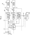
- the overcurrent cutoff circuit 42 is a switch circuit capable of cutting off a current when a current of a predetermined value or more flows through the power line L3 for a predetermined time or longer.
- the power line L3 is provided with a current sensor 48 that detects a current value.
- the current value detected by the current sensor 48 is input to the overcurrent cutoff circuit 42.
- the overcurrent cutoff circuit 42 cuts off a connection between each electric actuator 80 and the second DC power supply unit 20 in a case where the current value detected by the current sensor 48 is equal to or larger than a predetermined value for a predetermined time or longer.
- the overcurrent cutoff circuit 42 is controlled by the control unit 44.
- the control unit 44 is connected to a voltage sensor 14 that detects a voltage between terminals of the battery 30 and a current sensor 16 that detects a charge/discharge current of the battery 30.
- the control unit 44 calculates a storage rate A of the battery 30 on the basis of the voltage between the terminals of the battery 30 input from the voltage sensor 14 and the charge/discharge current of the battery 30 input from the current sensor 16.
- the regenerative power processing mode is a mode in which the battery 30 is charged with the generated regenerative power when the regenerative power is generated by the plurality of electric actuators 80 during a normal operation.
- the control unit 44 controls the step-up/down converter 41 to charge the battery 30 with the regenerative power from the power line L2.
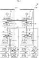
- the diode 50 is provided between the second DC power supply unit 20 and the DC bus L1. Therefore, in a case where the regenerative power is generated by the plurality of electric actuators 80, the regenerative power does not flow to the DC bus L1 and the battery 30 can be charged under the control of the step-up/down converter 41.
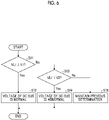
- step S50 the control unit 44 proceeds to step S30 and executes the regenerative power processing mode. Therefore, even if it is determined that the voltage VL2 is less than the threshold value Vr during the execution of the regenerative power processing mode, the regenerative power processing mode is continued until the predetermined standby time elapses. In a case where the voltage VL2 returns to a state of being equal to or more than the threshold value Vr (Yes in step S20) before the predetermined standby time elapses, the electric actuator 80 is in a state perform generating the regenerative power, and thus the execution of the regenerative power processing mode is continued (step S30).
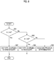
- step S63 the control unit 44 proceeds to step S65 and maintains the previous determination. That is, in a case where the storage rate A is brought into a state of being less than the first storage rate A1 (No in step S61), it is determined that the battery 30 is not required to be charged until the storage rate A is brought into to being lower than the second storage rate A2 (Yes in step S63). Therefore, in a case where it is temporarily determined that the battery 30 is not required to be charged, the determination that the battery 30 is not required to be charged is continued unless the storage rate A decreases to less than the second storage rate A2.
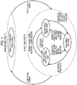
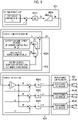
- Fig. 9 is an explanatory diagram illustrating an example of a control block for the step-up/down converter during a normal operation in which the first DC power supply unit can be used normally
- Fig. 10 is an explanatory diagram illustrating an example of a control block for the step-up/down converter during an emergency operation in which the first DC power supply unit cannot be used normally.
- a series of processes illustrated in Figs. 9 and 10 is repeatedly performed in every predetermined switching cycle (for example, 1/40 kHz) of the step-up/down converter 41.
- each switching element 411 of the step-up/down converter 41 is controlled turned on and off in a predetermined switching cycle on the basis of each gate signal P.
- charging and discharging of the battery 30 can be controlled during a normal operation in correspondence to the power running assist mode, the constant current charging mode, and the regenerative power processing mode.
- part of regenerative power generated by one electric actuator 80 can be supplied to another electric actuator 80.
- the electric power is suppressed from being supplied from the battery 30 to the electric actuator 80. Therefore, it is possible to suppress a decrease in the storage rate A of the battery 30.
Landscapes
- Engineering & Computer Science (AREA)
- Aviation & Aerospace Engineering (AREA)
- Power Engineering (AREA)
- Charge And Discharge Circuits For Batteries Or The Like (AREA)
- Protection Of Static Devices (AREA)
- Dc-Dc Converters (AREA)
Applications Claiming Priority (2)
| Application Number | Priority Date | Filing Date | Title |
|---|---|---|---|
| JP2019153703A JP7330817B2 (ja) | 2019-08-26 | 2019-08-26 | 配電システムおよび配電方法 |
| PCT/JP2020/031024 WO2021039475A1 (ja) | 2019-08-26 | 2020-08-17 | 配電システムおよび配電方法 |
Publications (2)
| Publication Number | Publication Date |
|---|---|
| EP4001122A1 true EP4001122A1 (de) | 2022-05-25 |
| EP4001122A4 EP4001122A4 (de) | 2022-11-30 |
Family
ID=74676229
Family Applications (1)
| Application Number | Title | Priority Date | Filing Date |
|---|---|---|---|
| EP20859118.0A Pending EP4001122A4 (de) | 2019-08-26 | 2020-08-17 | Stromverteilungssystem und stromverteilungsverfahren |
Country Status (4)
| Country | Link |
|---|---|
| US (1) | US11708171B2 (de) |
| EP (1) | EP4001122A4 (de) |
| JP (1) | JP7330817B2 (de) |
| WO (1) | WO2021039475A1 (de) |
Families Citing this family (4)
| Publication number | Priority date | Publication date | Assignee | Title |
|---|---|---|---|---|
| JP7134253B2 (ja) * | 2018-12-11 | 2022-09-09 | 本田技研工業株式会社 | ワーク検査装置及びワーク検査方法 |
| JP7793444B2 (ja) * | 2022-03-25 | 2026-01-05 | 本田技研工業株式会社 | 充電制御システム及び充電制御方法並びに航空機 |
| JP7744282B2 (ja) * | 2022-03-30 | 2025-09-25 | 本田技研工業株式会社 | 航空機の制御装置 |
| US12003132B2 (en) * | 2022-05-17 | 2024-06-04 | Hamilton Sundstrand Corporation | Hybrid electric secondary power and battery charging architecture and control system |
Family Cites Families (9)
| Publication number | Priority date | Publication date | Assignee | Title |
|---|---|---|---|---|
| JPS6181132A (ja) * | 1984-09-25 | 1986-04-24 | 三菱重工業株式会社 | 航空機用多重電源方式 |
| US9614465B2 (en) | 2011-07-26 | 2017-04-04 | Moog Inc. | Electric motor clamping system |
| JP5474898B2 (ja) | 2011-09-14 | 2014-04-16 | 本田技研工業株式会社 | 燃料電池車両 |
| US20140197681A1 (en) * | 2012-07-30 | 2014-07-17 | The Boeing Company | Electric system stabilizing system for aircraft |
| US9553467B2 (en) | 2013-11-05 | 2017-01-24 | Nabtesco Corporation | Distribution apparatus |
| JP6502758B2 (ja) * | 2015-06-15 | 2019-04-17 | 川崎重工業株式会社 | 直流安定化電源システム |
| MX393247B (es) * | 2016-09-06 | 2025-03-24 | Nissan Motor | Metodo de control y dispositivo de control para vehiculo hibrido. |
| WO2018175349A1 (en) * | 2017-03-19 | 2018-09-27 | Zunum Aero, Inc. | Hybrid-electric aircraft, and methods, apparatus and systems for facilitating same |
| JP7048313B2 (ja) * | 2017-12-28 | 2022-04-05 | 株式会社日立製作所 | 鉄道車両に備えられた蓄電装置の充放電を制御する制御装置及び制御方法 |
-
2019
- 2019-08-26 JP JP2019153703A patent/JP7330817B2/ja active Active
-
2020
- 2020-08-17 EP EP20859118.0A patent/EP4001122A4/de active Pending
- 2020-08-17 US US17/632,704 patent/US11708171B2/en active Active
- 2020-08-17 WO PCT/JP2020/031024 patent/WO2021039475A1/ja not_active Ceased
Also Published As
| Publication number | Publication date |
|---|---|
| US20220281612A1 (en) | 2022-09-08 |
| WO2021039475A1 (ja) | 2021-03-04 |
| JP2021035177A (ja) | 2021-03-01 |
| EP4001122A4 (de) | 2022-11-30 |
| JP7330817B2 (ja) | 2023-08-22 |
| US11708171B2 (en) | 2023-07-25 |
Similar Documents
| Publication | Publication Date | Title |
|---|---|---|
| EP4001122A1 (de) | Stromverteilungssystem und stromverteilungsverfahren | |
| US10992169B2 (en) | Vehicle-mounted backup device | |
| EP3190682B1 (de) | Stromversorgungssysteme und verfahren | |
| EP3444922B1 (de) | Unterbrechungsfreie stromversorgung | |
| US11190047B2 (en) | Uninterruptible power supply system including a plurality of uninterruptible power supplies connected in parallel | |
| CN110116621B (zh) | 电源系统 | |
| EP2648322B1 (de) | Überbrückungsschaltung bei Stromunterbrechung | |
| EP3591798A1 (de) | Unterbrechungsfreie stromversorgungsanlage mit energiespeichersystem | |
| JP6678342B2 (ja) | 電力供給システム、及び蓄電装置 | |
| EP3096435B1 (de) | Unterbrechungsfreies stromversorgungssystem mit störungsbehebungsfähigkeit | |
| KR20210075130A (ko) | 중간 회로 커패시터, 전력 변환기, 및 차량을 방전시키기 위한 장치 및 방법 | |
| EP2850717A1 (de) | Aufzugnotstromversorgung | |
| CN114944694A (zh) | 电源设备和控制方法 | |
| JP2016086506A (ja) | 電池監視装置及び方法 | |
| KR20150141315A (ko) | 인버터의 순간 정전 보상 방법 | |
| KR102369134B1 (ko) | 수중 이동체에서 전력 조절을 위한 방법 및 수중 이동체 | |
| JP2007290845A (ja) | エレベータシステムおよびバッテリユニット | |
| KR20200134976A (ko) | 배터리 시스템 및 이의 릴레이 제어 장치 | |
| KR20180099277A (ko) | 에너지 저장 장치를 포함하는 무정전 전원 공급 시스템 | |
| CN111316532B (zh) | 充电器 | |
| JP2014174944A (ja) | 多重電源装置、多重電源装置の制御方法、及びプログラム | |
| EP3640175B1 (de) | Dezentralisierte leistungsverwaltung in einer aufzugsanlage | |
| US12418258B2 (en) | Motor control device | |
| KR20140030740A (ko) | 전력계통에서 개폐기를 이용한 부하 차단 장치 및 방법 | |
| JP2001008382A (ja) | 無停電工事用電源装置 |
Legal Events
| Date | Code | Title | Description |
|---|---|---|---|
| STAA | Information on the status of an ep patent application or granted ep patent |
Free format text: STATUS: THE INTERNATIONAL PUBLICATION HAS BEEN MADE |
|
| PUAI | Public reference made under article 153(3) epc to a published international application that has entered the european phase |
Free format text: ORIGINAL CODE: 0009012 |
|
| STAA | Information on the status of an ep patent application or granted ep patent |
Free format text: STATUS: REQUEST FOR EXAMINATION WAS MADE |
|
| 17P | Request for examination filed |
Effective date: 20220216 |
|
| AK | Designated contracting states |
Kind code of ref document: A1 Designated state(s): AL AT BE BG CH CY CZ DE DK EE ES FI FR GB GR HR HU IE IS IT LI LT LU LV MC MK MT NL NO PL PT RO RS SE SI SK SM TR |
|
| A4 | Supplementary search report drawn up and despatched |
Effective date: 20221103 |
|
| DAV | Request for validation of the european patent (deleted) | ||
| DAX | Request for extension of the european patent (deleted) | ||
| RIC1 | Information provided on ipc code assigned before grant |
Ipc: H02J 1/10 20060101ALN20221027BHEP Ipc: H02H 3/087 20060101ALN20221027BHEP Ipc: H02J 7/14 20060101ALI20221027BHEP Ipc: H02J 7/00 20060101ALI20221027BHEP Ipc: H02J 1/08 20060101ALI20221027BHEP Ipc: H02H 7/18 20060101ALI20221027BHEP Ipc: B64D 41/00 20060101AFI20221027BHEP |