EP2648322B1 - Überbrückungsschaltung bei Stromunterbrechung - Google Patents
Überbrückungsschaltung bei Stromunterbrechung Download PDFInfo
- Publication number
- EP2648322B1 EP2648322B1 EP20130153421 EP13153421A EP2648322B1 EP 2648322 B1 EP2648322 B1 EP 2648322B1 EP 20130153421 EP20130153421 EP 20130153421 EP 13153421 A EP13153421 A EP 13153421A EP 2648322 B1 EP2648322 B1 EP 2648322B1
- Authority
- EP
- European Patent Office
- Prior art keywords
- power
- emergency
- controller
- circuit
- state
- Prior art date
- Legal status (The legal status is an assumption and is not a legal conclusion. Google has not performed a legal analysis and makes no representation as to the accuracy of the status listed.)
- Active
Links
- 238000012544 monitoring process Methods 0.000 claims description 17
- 230000007704 transition Effects 0.000 claims description 9
- 238000000034 method Methods 0.000 claims description 7
- 230000000779 depleting effect Effects 0.000 claims description 6
- 239000003990 capacitor Substances 0.000 claims description 4
- 239000000446 fuel Substances 0.000 claims description 2
- 238000010586 diagram Methods 0.000 description 6
- 230000007423 decrease Effects 0.000 description 1
- 239000000463 material Substances 0.000 description 1
- 238000012986 modification Methods 0.000 description 1
- 230000004048 modification Effects 0.000 description 1
Images


Classifications
-
- B—PERFORMING OPERATIONS; TRANSPORTING
- B64—AIRCRAFT; AVIATION; COSMONAUTICS
- B64D—EQUIPMENT FOR FITTING IN OR TO AIRCRAFT; FLIGHT SUITS; PARACHUTES; ARRANGEMENTS OR MOUNTING OF POWER PLANTS OR PROPULSION TRANSMISSIONS IN AIRCRAFT
- B64D41/00—Power installations for auxiliary purposes
- B64D41/007—Ram air turbines
-
- H—ELECTRICITY
- H02—GENERATION; CONVERSION OR DISTRIBUTION OF ELECTRIC POWER
- H02J—CIRCUIT ARRANGEMENTS OR SYSTEMS FOR SUPPLYING OR DISTRIBUTING ELECTRIC POWER; SYSTEMS FOR STORING ELECTRIC ENERGY
- H02J9/00—Circuit arrangements for emergency or stand-by power supply, e.g. for emergency lighting
- H02J9/04—Circuit arrangements for emergency or stand-by power supply, e.g. for emergency lighting in which the distribution system is disconnected from the normal source and connected to a standby source
- H02J9/06—Circuit arrangements for emergency or stand-by power supply, e.g. for emergency lighting in which the distribution system is disconnected from the normal source and connected to a standby source with automatic change-over, e.g. UPS systems
- H02J9/062—Circuit arrangements for emergency or stand-by power supply, e.g. for emergency lighting in which the distribution system is disconnected from the normal source and connected to a standby source with automatic change-over, e.g. UPS systems for AC powered loads
-
- B—PERFORMING OPERATIONS; TRANSPORTING
- B64—AIRCRAFT; AVIATION; COSMONAUTICS
- B64D—EQUIPMENT FOR FITTING IN OR TO AIRCRAFT; FLIGHT SUITS; PARACHUTES; ARRANGEMENTS OR MOUNTING OF POWER PLANTS OR PROPULSION TRANSMISSIONS IN AIRCRAFT
- B64D2221/00—Electric power distribution systems onboard aircraft
-
- H—ELECTRICITY
- H02—GENERATION; CONVERSION OR DISTRIBUTION OF ELECTRIC POWER
- H02J—CIRCUIT ARRANGEMENTS OR SYSTEMS FOR SUPPLYING OR DISTRIBUTING ELECTRIC POWER; SYSTEMS FOR STORING ELECTRIC ENERGY
- H02J2310/00—The network for supplying or distributing electric power characterised by its spatial reach or by the load
- H02J2310/40—The network being an on-board power network, i.e. within a vehicle
- H02J2310/44—The network being an on-board power network, i.e. within a vehicle for aircrafts
Definitions
- the present invention is related to power distribution systems and in particular to controllers employed in conjunction with power distribution systems.
- Controllers such as bus power control units (BPCUs) and emergency power controllers (EMPCs) are responsible for monitoring and controlling the operation of the electrical power distribution system.
- BPCU bus power control units
- EMPC emergency power controllers
- a BPCU is responsible for monitoring operation of the power distribution system and providing commands to selectively control the operation of various relays and/or contactors to selectively route power through various buses.
- an EMPC is responsible for monitoring and providing command instructions to relays and/or contactors within the emergency power system to selectively route power to desired buses.
- the EMPC may also be responsible for deploying an RAM Air Turbine (RAT) generator for the purpose of generating emergency power.
- RAT RAM Air Turbine
- Both the BPCUs and the EMPCs require power to operation, typically derived from one or more of the power buses the units are charged with monitoring and controlling. A loss of power on all of the power buses results in an undesirable loss of operational power in the BPCUs and EMPCs.
- US 2008/0155294 discloses a power supply for an image forming apparatus that includes a capacitor that powers the printer when its rectified power source voltage drops below a threshold.
- US 2006/0061213 discloses an electric vehicle with redundant generators and distribution buses in lieu of bleed air pneumatics or other mechanical power sources.
- a controller is employed in conjunction with an electrical power distribution system (EPDS).
- EPDS electrical power distribution system
- the present invention provides a controller according to claim 1 for providing control commands associated with at least one of an alternating current (AC) power bus and a direct current (DC) power bus, the controller comprising: at least a first input for receiving DC power from a DC power bus (DC Input); a power supply circuit connected to the first input to receive DC power that is used to power the controller; and a power interrupt bridge circuit connected to monitor a voltage provided by the DC power bus (DC Input) and in response to the monitored voltage being less than a threshold value supplies power to the power supply circuit from a DC emergency power source for only a defined time period to ensure the controller remains powered, characterised in that the power interrupt bridge circuit comprises a time constant selector that stores the defined time period which is sufficient to allow the controller to provide emergency commands necessary to transition the power distribution system to the desired safe operating mode or emergency operating mode and to connect essential buses and/or loads to emergency power sources such as a RAM Air Turbine generator without fully depleting the DC emergency power source (DC_EMER).
- DC_EMER DC emergency power source
- the present invention provides a method according to claim 10 of supplying power to a controller during emergency operations, the method comprising: monitoring a voltage associated with operational power provided to the controller; comparing the monitored voltage to a threshold value to detect a low voltage condition; connecting an emergency DC power supply (DC_EMER) to supply operational power to the controller in response to the monitored voltage being less than the threshold value; and disconnecting the emergency DC power supply from the controller upon expiration of a defined time period, characterised in that the time period is sufficient to allow the controller to provide emergency commands necessary to transition the power distribution system to the desired safe operating mode or emergency operating mode and to connect essential buses and/or loads to emergency power sources such as a RAM Air Turbine generator without fully depleting the emergency power supply (DC_EMER).
- DC_EMER emergency DC power supply
- the present invention is directed to a controller, such as a bus power control unit (BPCU) and/or emergency power controller (EMPC).
- the controller includes a power interrupt bridge circuit that monitors voltage on a DC bus that provides operational power to the controller, and compares the monitored DC voltage to a threshold. If the monitored DC voltage decreases below a threshold value, then the power interrupt bridge circuit supplies power to a DC output from an emergency DC power source for a defined period of time. In this way, the controller remains powered even during a loss of "normal" power.
- BPCU bus power control unit
- EMPC emergency power controller
- FIGS. 1A and 1B are circuit diagrams of a bus power control unit (BPCU) and emergency power controller (EMPC), respectively, employed as part of an electrical power distribution system (EPDS) according to an embodiment of the present invention.
- BPCU bus power control unit
- EMPC emergency power controller
- FIG. 1A illustrates BPCU 10 connected to receive "normal" operating power from DC power bus DC _ Input , and emergency power from DC emergency bus DC_EMER.
- BPCU 10 includes power interruption bridge circuit 12, diodes D1 and D2, power supply circuit 14, and micro-controller 16.
- power supplied by DC power bus DC _ Input is provided via diode D2 to power supply circuit 14, which supplies operational power to micro-controller 16.
- BPCU may receive power from a plurality of DC power buses, each of which is provided via a separate diode (creating a diode OR circuit) to power supply circuit 14.
- Power interruption bridge circuit 12 monitors the voltage provided by DC power bus DC_Input. In the event the monitored voltage falls below a threshold level, power interruption bridge circuit 12 operates to supply power from DC emergency bus DC_EMER through diode D1 to power supply circuit 14 for a defined period of time.
- power derived from the DC emergency bus DC_EMER is provided via one or more packs of batteries, referred to as a battery-direct bus.
- DC emergency bus DC_EMER may derive power from other emergency power sources.
- emergency power sources are only capable of providing a limited amount of power for a limited amount of time.
- power supply circuit 14 remains powered for a defined period of time based on power supplied by power interruption bridge circuit.
- power interruption bridge circuit prevents power from being supplied by DC emergency bus DC_EMER to power supply circuit 14 to prevent depletion of the DC emergency bus source (e.g., batteries).
- the DC emergency bus source e.g., batteries.
- BPCU remains operational and can transition the power distribution system from a nonnal operating mode to a "safe" or "emergency" operating mode.
- microcontroller 16 generates commands/instructions provided to contactors and/or relay drivers 18 to transition the power distribution system to the desired safe operating mode.
- This may include disconnecting non-essential buses and/or loads, and connecting essential buses and/or loads to emergency power sources such as a RAM Air Turbine (RAT) generator.
- RAT RAM Air Turbine
- the defined period of time power interruption bridge circuit supplies power to power supply circuit 14 is defined to ensure micro-controller 16 has sufficient time to generate the commands/instructions necessary to transition the power distribution system to the desired safe operating mode or emergency operating mode.
- FIG. 1B illustrates another type of controller, emergency power controller 20, in which the power interruption bridge circuit may be utilized.
- EMPC 20 is connected to receive "normal" operating power from DC power bus DC_Input, and emergency power from DC emergency bus DC_EMER.
- EMPC 20 includes power interruption bridge circuit 22, diodes D3 and D4, power supply circuit 24, and micro-controller 26.
- power supplied by DC power bus DC_Input is provided via diode D4 to power supply circuit 24, which supplies operational power to micro-controller 26.
- EMPC 20 may receive power from a plurality of DC power buses, each of which is provided via a separate diode (creating a diode OR circuit) to power supply circuit 24.
- Power interruption bridge circuit 22 monitors the voltage provided by DC power bus DC_Input. In the event the monitored voltage falls below a threshold level, power interruption bridge circuit 22 operates to supply power from DC emergency bus DC_EMER through diode D3 to power supply circuit 24 for a defined period of time.
- power derived from the DC emergency bus DC_EMER is provided via one or more packs of batteries, referred to as a battery-direct bus.
- DC emergency bus DC_EMER may derive power from other emergency power sources capable of providing power for limited periods of time (e.g., fuel cells, capacitors, super capacitors, etc.).. Typically, emergency power sources are only capable of providing a limited amount of power for a limited amount of time.
- power supply circuit 24 remains powered for a defined period of time based on power supplied by power interruption bridge circuit.
- power interruption bridge circuit 22 prevents power from being supplied by DC emergency bus DC_EMER to power supply circuit 24 to prevent depletion of the DC emergency bus source (e.g., batteries).
- the DC emergency bus source e.g., batteries.
- EMPC 20 remains operational and can transition the power distribution system from a normal operating mode to a "safe" or "emergency" operating mode. As described with respect to FIG.
- this may include generating commands/instructions provided to contractors and/or relay drivers 28 to transition the power distribution system to the desired safe operating mode. This may include disconnecting non-essential buses and/or loads, and connecting essential buses and/or loads to emergency power sources such as a RAM Air Turbine (RAT) generator.
- RAT RAM Air Turbine
- EMPC 20 is responsible for deploying RAM Air Turbine (RAT) generator 30 in response to an emergency loss of power.
- RAT RAM Air Turbine
- the defined period of time power interruption bridge circuit 22 maintains power to power supply circuit 24 is selected, in part, to ensure micro-controller 26 has sufficient time to deploy RAT 30.
- the defined period of time may also be selected based on time required to send command/instructions to contactors/relay drivers 28.
- FIG. 2 is a circuit diagram of BPCU 10 and/or EMPC 20 (referred to generically as "controller 10, 20") according to an embodiment of the present invention.
- Circuit elements previously described with respect to FIGS. 1A and 1B are described here with reference to both reference numbers.
- diode D2 shown in FIG. 1A
- diode D4 shown in FIG. 1B
- diode D2 is referred to here as diode D2
- diode D1 shown in FIG. 1A
- diode D3 shown in FIG. 1B
- power interruption bridge circuit 12 shown in FIG. 1A
- power interruption bridge circuit 22 shown in FIG. 1B
- power supply circuit 14 shown in FIG. 1A
- power supply circuit 24 shown in FIG. 1B
- power supply circuit 14, 24 is represented as power supply circuit 14, 24.
- FIG. 2 illustrates in additional detail the operation of power interruption bridge circuit 12, 22, which includes voltage monitoring/comparator 32, time constant selector 34, trigger circuit 36, and power switch 38.
- controller 10, 20 receives "normal" operational power from DC power bus DC_Input. Additionally, controller 10, 20 is connected to receive DC power from an emergency DC bus DC_EMER.
- Voltage monitoring/comparator circuit 32 monitors the voltage provided by DC bus DC_Input to detect low voltage conditions indicative of a potential fault. If the monitored voltage falls below the threshold value associated with or programmed into voltage monitoring/comparator circuit 32, a trigger signal is provided to the input of trigger circuit 36. In response, trigger circuit 36 turns ON power switch 38, creating a circuit path from the DC emergency bus DC_EMER through diode D1, D3 to power supply circuit 14, 24. In this way, controller 10, 20 remains powered despite the potential loss of power associated with DC power bus DC_Input.
- the duration of time trigger circuit 36 maintains power switch 38 in the On state is determined based on the value k stored by time constant selector 34, which is selected based on the particular application.
- the time value stored by time circuit 34 is selected to ensure that controller 10 remains powered for a duration of time sufficient to allow controller to provide emergency commands/instructions to the power distribution system, without fully depleting the power source associated with DC emergency bus DC_EMER.
- controller 10, 20 is an emergency power controller (EMPC) (as shown in FIG. 1B )
- the time constant k is selected to ensure controller 10, 20 receives operational power long enough to deploy RAT 30 (shown in FIG. 1B ).
- trigger circuit 36 turns power switch 38 Off, thereby disconnecting the DC emergency bus DC_EMER from supplying power to power supply circuit 14, 24.
- the expiration of the defined time period results in controller 10, 20 remaining unpowered until "normal" power sources are restored.
- the time period is defined such that at the end of the defined time period, emergency power such as that provided by RAT 30 (shown in FIG. 1B ) provides operational power to controller 10, 20.
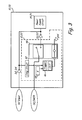
- FIG. 3 is a circuit diagram of another embodiment of BPCU 10 and/or EMPC 20 (referred to generically as "controller 10, 20").
- controller 10, 20 circuit elements previously described with respect to FIGS. 1A and 1B are described here with reference to both reference numbers.
- diode D2 shown in FIG. 1A
- diode D4 shown in FIG. 1B
- diode D2 is referred to here as diode D2
- diode D1 shown in FIG. 1A
- diode D3 shown in FIG. 1B
- power interruption bridge circuit 12 shown in FIG. 1A
- power interruption bridge circuit 22 shown in FIG. 1B
- power supply circuit 14 shown in FIG. 1A
- power supply circuit 24 shown in FIG. 1B
- power supply circuit 14, 24 is represented as power supply circuit 14, 24.
- FIG. 3 illustrates in additional detail the operation of power interruption bridge circuit 12, 22, which includes voltage monitoring/comparator 42, time constant selector 44, trigger circuit 46, and relay 48.
- controller 10, 20 receives "normal" operational power from DC power bus DC_Input. Additionally, controller 10, 20 is connected to receive DC power from an emergency DC bus DC_EMER.
- voltage monitoring/comparator 42 monitors the voltage provided by DC power bus DC_Input to a threshold. If the monitored voltage falls below the threshold value associated with or programmed into voltage monitoring/comparator circuit 42, a trigger signal is provided to the input of trigger circuit 46. In response, trigger circuit 46 creates a circuit path from DC power bus DC_Input through trigger circuit 46 and relay 48 to ground. The resulting circuit path energizes relay 48, creating a circuit path between DC emergency bus DC_EMER and power supply circuit 14, 24. In this way, controller 10, 20 remains powered despite the potential loss of power associated with DC power bus DC_Input.
- the duration of time trigger circuit 46 maintains power switch 38 in the On state is determined based on the value k stored by time constant selector 44, which is selected based on the particular application. As discussed above with respect to FIG. 2 , the time value k stored by time constant selector 44 is selected to ensure that controller 10, 20 remains powered for a duration of time sufficient to allow controller to provide emergency commands/instructions to the power distribution system, without fully depleting the power source associated with DC emergency bus DC_EMER.
- trigger circuit 46 turns Off, thereby de-energizing relay 48 and disconnecting DC emergency power DC_EMER from supplying power to power supply circuit 14, 24.
- the duration of the time period is selected based on the application to allow controller 10, 20 to remain operational long enough to configure the system for emergency operation and/or deploy emergency power systems (e.g., RAT).
Claims (13)
- Steuereinrichtung (10; 20) zum Bereitstellen von Steuerbefehlen im Zusammenhang mit wenigstens einer Wechselstrom-(AC)-Stromschiene und einer Gleichstrom-(DC)-Stromschiene, wobei die Steuereinrichtung Folgendes umfasst:wenigstens einen ersten Eingang zum Empfangen von Gleichstrom von einer Gleichstromschiene (DC-Eingang);eine Stromversorgungsschaltung (14; 24), die mit dem ersten Eingang verbunden ist, um Gleichstrom zu empfangen, der zum Betreiben der Steuereinrichtung (10; 20) benutzt wird; undeine Stromunterbrechungsüberbrückungsschaltung (12; 22), die verbunden ist, um eine Spannung zu überwachen, die von der Gleichstromschiene (DC-Eingang) bereitgestellt wird, und in Reaktion darauf, dass die überwachte Spannung kleiner als ein Schwellenwert ist, nur für eine definierten Zeitspanne (K) Strom von einer DC-Notstromquelle an die Stromversorgungsschaltung (14; 24) bereitstellt, um sicherzustellen, dass die Steuereinrichtung weiterhin mit Strom versorgt wird,dadurch gekennzeichnet, dass die Stromunterbrechungsüberbrückungsschaltung (12; 22) einen Zeitkonstantenwähler (34; 44) umfasst, der die definierte Zeitspanne (k) speichert, die ausreicht, um es der Steuereinrichtung (10; 20) zu ermöglichen, Notbefehle bereitzustellen, die für einen Übergang des Stromverteilungssystems in den gewünschten sicheren Betriebsmodus oder Notbetriebsmodus und zum Verbinden wesentlicher Schienen und/oder Lasten an Notstromquellen wie einen Staudruckturbinengenerator notwendig sind, ohne die DC-Notstromquelle (DC_EMER) vollständig zu entleeren.
- Steuereinrichtung nach Anspruch 1, wobei die Stromunterbrechungsüberbrückungsschaltung (12; 22) Folgendes aufweist:eine Überwachungs-/Vergleichsschaltung (42), die die von der Gleichstromschiene bereitgestellte Spannung überwacht und ein Auslösesignal bereitstellt, wenn die überwachte Spannung kleiner als ein Schwellenwert ist;eine Relaisschaltung (48) mit einem ersten Zustand und einem zweiten Zustand, wobei die Relaisschaltung im ersten Zustand die DC-Notstromquelle mit der Stromversorgungsschaltung verbindet und im zweiten Zustand die Verbindung der DC-Notstromquelle mit der Stromversorgungsschaltung verhindert; undeine Auslöseschaltung (46), die verbunden ist, um in Reaktion auf das Auslösesignal von der Überwachungs-/Vergleichsschaltung die Relaisschaltung in den ersten Zustand zu versetzen und die Relaisschaltung bei Ablauf der definierten Zeitspanne in den zweiten Zustand zu versetzen.
- Steuereinrichtung nach Anspruch 1, wobei die Stromunterbrechungsüberbrückungsschaltung Folgendes aufweist:eine Überwachungs-/Vergleichsschaltung (32), die die von der Gleichstromschiene bereitgestellte Spannung überwacht und ein Auslösesignal bereitstellt, wenn die überwachte Spannung kleiner als ein Schwellenwert ist;einen Festkörperschalter (38) mit einem ersten Zustand und einem zweiten Zustand, wobei der Festkörperschalter im ersten Zustand die DC-Notstromquelle mit der Stromversorgungsschaltung verbindet und im zweiten Zustand die Verbindung der DC-Notstromquelle mit der Stromversorgungsschaltung verhindert; undeine Auslöseschaltung (36), die verbunden ist, um in Reaktion auf das Auslösesignal von der Überwachungs-/Vergleichsschaltung den Festkörperschalter (38) in den ersten Zustand zu versetzen und den Festkörperschalter bei Ablauf der definierten Zeitspanne in den zweiten Zustand zu versetzen.
- Steuereinrichtung nach Anspruch 1, 2 oder 3, wobei die DC-Notstromquelle (DC_EMER) ausgewählt ist aus einer Gruppe bestehend aus wenigstens einem von: einer Batterie, einem Kondensator und einer Brennstoffzelle.
- Steuereinrichtung nach einem der vorangehenden Ansprüche, wobei die Steuereinrichtung (10) eine Schienenstromsteuereinheit (BPCU) ist, die Befehle an ein oder mehrere Relais und/oder Schütz(e) (18) bereitstellt.
- Steuereinrichtung nach einem der vorangehenden Ansprüche, wobei die Steuereinrichtung (10; 20) in Verbindung mit einer Staudruckturbine (RAT) (30) benutzt wird und Einsatzanweisungen an die RAT bereitstellt; wobei vorzugsweise die definierte Zeitspanne (k) größer als eine Zeit ist, die zum Einsetzen der RAT (30) in Reaktion auf einen erkannten Stromverlust benötigt wird.
- Steuereinrichtung nach einem der vorangehenden Ansprüche (20), wobei die Steuereinrichtung eine Notstromsteuereinheit (EMPC) ist.
- Stromverteilungssystem, umfassend:eine Gleichstrom-(DC)-Stromschiene (DC-Eingang);eine DC-Notstromschiene (DC_EMER);einen Staudruckturbinen-(RAT)-Generator (30), der eingesetzt wird, um Notstrom zu erzeugen;eine Notstromsteuereinrichtung (EMPC) (20) nach einem der Ansprüche 1 bis 6.
- Stromverteilungssystem nach Anspruch 8, wobei die definierte Zeitspanne (k) größer als eine Zeit ist, die zum Einsetzen der RAT (30) in Reaktion auf einen erkannten Stromverlust benötigt wird.
- Verfahren zum Versorgen einer Steuereinrichtung (10; 20) mit Strom bei Notbetriebsvorgängen, wobei das Verfahren Folgendes umfasst:Überwachen einer Spannung im Zusammenhang mit Betriebsstrom, der an die Steuereinrichtung bereitgestellt wird;Vergleichen der überwachten Spannung mit einem Schwellenwert, um einen Niederspannungszustand zu erkennen;Verbinden einer DC-Notstromversorgung (DC_EMER), um in Reaktion darauf, dass die überwachte Spannung kleiner als der Schwellenwert ist, die Steuereinrichtung mit Betriebsstrom zu versorgen; undTrennen der DC-Notstromversorgung von der Steuereinrichtung, wenn eine definierte Zeitspanne (k) abgelaufen ist,dadurch gekennzeichnet, dass die Zeitspanne (k) ausreicht, um es der Steuereinrichtung (10; 20) zu ermöglichen, Notbefehle bereitzustellen, die für einen Übergang des Stromverteilungssystems in den gewünschten sicheren Betriebsmodus oder Notbetriebsmodus und zum Verbinden wesentlicher Schienen und/oder Lasten an Notstromquellen wie einen Staudruckturbinengenerator notwendig sind, ohne die DC-Notstromquelle (DC_EMER) vollständig zu entleeren.
- Verfahren nach Anspruch 10, wobei die Steuereinrichtung (20) eine Notstromsteuereinrichtung (EMPC) ist, die in Verbindung mit einem elektrischen Stromzentrum (EPC) benutzt wird, wobei die EMPC Strom von der DC-Notstromversorgung nutzt, um einen Staudruckturbinen-(RAT)-Generator (30) zum Erzeugen von Notstrom einzusetzen.
- Verfahren nach Anspruch 11, wobei die definierte Zeitspanne (k) größer als eine Zeit ist, die von der EMPC zum Einsetzen der RAT (30) in Reaktion auf einen erkannten Stromverlust benötigt wird.
- Verfahren nach Anspruch 10, 11 oder 12, wobei die Steuereinrichtung (10) eine Schienenstromsteuereinheit (BPCU) ist, wobei die BPCU Strom von der DC-Notstromversorgung nutzt, um Relais und/oder Schütze (18), die einem Stromverteilungssystem zugeordnet sind, auf einen gewünschten Zustand für den Notbetrieb zu konfigurieren.
Applications Claiming Priority (1)
| Application Number | Priority Date | Filing Date | Title |
|---|---|---|---|
| US13/440,060 US9789973B2 (en) | 2012-04-05 | 2012-04-05 | Power interruption bridge circuit |
Publications (2)
| Publication Number | Publication Date |
|---|---|
| EP2648322A1 EP2648322A1 (de) | 2013-10-09 |
| EP2648322B1 true EP2648322B1 (de) | 2015-01-14 |
Family
ID=47632883
Family Applications (1)
| Application Number | Title | Priority Date | Filing Date |
|---|---|---|---|
| EP20130153421 Active EP2648322B1 (de) | 2012-04-05 | 2013-01-31 | Überbrückungsschaltung bei Stromunterbrechung |
Country Status (2)
| Country | Link |
|---|---|
| US (1) | US9789973B2 (de) |
| EP (1) | EP2648322B1 (de) |
Families Citing this family (9)
| Publication number | Priority date | Publication date | Assignee | Title |
|---|---|---|---|---|
| EP3148032B1 (de) * | 2015-09-28 | 2018-03-28 | GE Energy Power Conversion Technology Ltd | Stromversorgungssystem für eine anordnung von parallel angeschlossenen lasten an einen bus mit kontinuierlicher stromversorgung |
| JP7027027B2 (ja) * | 2016-03-17 | 2022-03-01 | キヤノン株式会社 | 情報処理装置、制御方法、およびそのプログラム |
| US10469250B2 (en) * | 2017-12-22 | 2019-11-05 | Max Adel Rady | Physical item mapping to blockchain framework |
| US10703502B2 (en) * | 2018-03-20 | 2020-07-07 | Hamilton Sunstrand Corporation | Emergency power system with energy storage device |
| US10322815B1 (en) | 2018-03-22 | 2019-06-18 | Hamilton Sundstrand Corporation | Stored electrical energy assisted ram air turbine (RAT) system |
| US11424642B2 (en) | 2019-03-22 | 2022-08-23 | Hamilton Sundstrand Corporation | Solid switch power distribution controller with storage device backup |
| US11616366B2 (en) | 2020-03-12 | 2023-03-28 | Hamilton Sundstrand Corporation | AC essential bus delta current and over current protection scheme |
| US11383855B2 (en) | 2020-03-18 | 2022-07-12 | Hamilton Sundstrand Corporation | DC bus voltage input into RAT auto-deploy |
| US20230378743A1 (en) * | 2022-05-20 | 2023-11-23 | Hamilton Sundstrand Corporation | Direct current bus control scheme |
Family Cites Families (19)
| Publication number | Priority date | Publication date | Assignee | Title |
|---|---|---|---|---|
| WO1996017260A1 (en) * | 1994-11-28 | 1996-06-06 | Analogic Corporation | Ups for medical imaging system |
| WO2001045230A1 (en) * | 1999-12-16 | 2001-06-21 | Mcandrews Enterprises Inc. | Spare bus power plant |
| JP2002025790A (ja) * | 2000-07-12 | 2002-01-25 | Koito Mfg Co Ltd | 放電灯点灯回路 |
| US7016171B2 (en) * | 2001-02-01 | 2006-03-21 | Hydro-Aire, Inc. | Current fault detector and circuit interrupter and packaging thereof |
| MXPA02007840A (es) * | 2001-08-15 | 2012-02-22 | Eltech Systems Corp | Sistemas y metodos para proteccion anodica. |
| US6862165B2 (en) * | 2003-06-06 | 2005-03-01 | Honeywell International Inc. | Method and apparatus for valve control |
| US7689852B2 (en) * | 2003-09-12 | 2010-03-30 | Broadcom Corporation | Method and system for providing power management for an integrated gigabit ethernet controller |
| JP4210200B2 (ja) * | 2003-11-11 | 2009-01-14 | 本田技研工業株式会社 | 車両用電源システム |
| US7439634B2 (en) | 2004-08-24 | 2008-10-21 | Honeywell International Inc. | Electrical starting, generation, conversion and distribution system architecture for a more electric vehicle |
| TWI298123B (en) * | 2005-07-11 | 2008-06-21 | Asrock Inc | Dc uninterruptible power supply and computer device using the same |
| US7750501B2 (en) * | 2005-10-27 | 2010-07-06 | Continental Automotive Systems Us, Inc. | System and method of over voltage control for a power system |
| US7949885B2 (en) * | 2006-12-22 | 2011-05-24 | Ricoh Company, Ltd. | Power supply device, image forming apparatus, and power supply method |
| US7872368B2 (en) * | 2008-10-24 | 2011-01-18 | The Boeing Company | Intelligent energy management architecture |
| US8829707B2 (en) * | 2010-07-15 | 2014-09-09 | Hamilton Sundstrand Corporation | Methods for aircraft emergency power management |
| US8344546B2 (en) * | 2010-07-16 | 2013-01-01 | Facebook, Inc. | Power supply unit directly connected to backup direct current power source |
| GB201015510D0 (en) * | 2010-09-16 | 2010-10-27 | Goodrich Actuation Systems Sas | Power supply system |
| US8738268B2 (en) * | 2011-03-10 | 2014-05-27 | The Boeing Company | Vehicle electrical power management and distribution |
| US8820677B2 (en) * | 2011-06-18 | 2014-09-02 | Jason A. Houdek | Aircraft power systems and methods |
| US20130181448A1 (en) * | 2012-01-17 | 2013-07-18 | Hamilton Sundstrand Corporation | Electric actuators in aircraft systems |
-
2012
- 2012-04-05 US US13/440,060 patent/US9789973B2/en active Active
-
2013
- 2013-01-31 EP EP20130153421 patent/EP2648322B1/de active Active
Also Published As
| Publication number | Publication date |
|---|---|
| US20130264878A1 (en) | 2013-10-10 |
| US9789973B2 (en) | 2017-10-17 |
| EP2648322A1 (de) | 2013-10-09 |
Similar Documents
| Publication | Publication Date | Title |
|---|---|---|
| EP2648322B1 (de) | Überbrückungsschaltung bei Stromunterbrechung | |
| US10003200B2 (en) | Decentralized module-based DC data center | |
| EP2408085B1 (de) | Verfahren für die Flugzeug-Notstromversorgung | |
| US9083201B2 (en) | Load shedding circuit for RAM air turbines | |
| AU2018227610B2 (en) | Extending black-start availability using energy storage systems | |
| CN108933476B (zh) | 用于操作电力系统架构的方法和设备 | |
| EP2850717B1 (de) | Aufzugnotstromversorgung | |
| WO2012124130A1 (ja) | 電力制御装置および電力制御方法 | |
| US10087902B2 (en) | Power limiting generator control unit (GCU) | |
| CN105576642B (zh) | 监视功率系统功率变换器的系统和方法 | |
| EP3883081A1 (de) | Gleichstrombusspannungseingang in automatischem rat-einsatz | |
| ES2742302T3 (es) | Distribución de carga y tensión de refuerzo en circuitos de aparatos de notificación | |
| US11708171B2 (en) | Power distribution system and power distribution method | |
| US9114888B2 (en) | RAM air turbine smoke isolation | |
| CN113022313A (zh) | Vcu断电保护电路、断电控制方法、系统和工程机械 | |
| CN112104037A (zh) | 电源系统及其控制方法、自动驾驶车辆和电源管理装置 | |
| KR101427680B1 (ko) | 고효율 전원 공급 장치 및 이를 이용한 전원 공급 방법 | |
| EP4280407A1 (de) | Steuerungsschema für gleichstrombus | |
| US11296506B2 (en) | Bidirectional charging panel | |
| CN112714990B (zh) | 提供电力的系统和方法 | |
| WO2024023305A1 (en) | An energy distribution system | |
| CN114499300A (zh) | 一种用于大功率电机起动和功率补偿的电路和控制逻辑 | |
| KR20140088393A (ko) | 전원 공급용 인터페이스 보드 | |
| KR20140088503A (ko) | 고효율 전원 공급 장치 및 이를 이용한 전원 공급 방법 | |
| KR20150112189A (ko) | 하이브리드 전력 제어장치 |
Legal Events
| Date | Code | Title | Description |
|---|---|---|---|
| PUAI | Public reference made under article 153(3) epc to a published international application that has entered the european phase |
Free format text: ORIGINAL CODE: 0009012 |
|
| AK | Designated contracting states |
Kind code of ref document: A1 Designated state(s): AL AT BE BG CH CY CZ DE DK EE ES FI FR GB GR HR HU IE IS IT LI LT LU LV MC MK MT NL NO PL PT RO RS SE SI SK SM TR |
|
| AX | Request for extension of the european patent |
Extension state: BA ME |
|
| 17P | Request for examination filed |
Effective date: 20140408 |
|
| RBV | Designated contracting states (corrected) |
Designated state(s): AL AT BE BG CH CY CZ DE DK EE ES FI FR GB GR HR HU IE IS IT LI LT LU LV MC MK MT NL NO PL PT RO RS SE SI SK SM TR |
|
| RIC1 | Information provided on ipc code assigned before grant |
Ipc: H02M 1/32 20070101AFI20140514BHEP Ipc: H02J 9/06 20060101ALI20140514BHEP Ipc: B64D 41/00 20060101ALI20140514BHEP |
|
| GRAP | Despatch of communication of intention to grant a patent |
Free format text: ORIGINAL CODE: EPIDOSNIGR1 |
|
| INTG | Intention to grant announced |
Effective date: 20140729 |
|
| GRAS | Grant fee paid |
Free format text: ORIGINAL CODE: EPIDOSNIGR3 |
|
| GRAA | (expected) grant |
Free format text: ORIGINAL CODE: 0009210 |
|
| AK | Designated contracting states |
Kind code of ref document: B1 Designated state(s): AL AT BE BG CH CY CZ DE DK EE ES FI FR GB GR HR HU IE IS IT LI LT LU LV MC MK MT NL NO PL PT RO RS SE SI SK SM TR |
|
| REG | Reference to a national code |
Ref country code: GB Ref legal event code: FG4D |
|
| REG | Reference to a national code |
Ref country code: CH Ref legal event code: EP |
|
| REG | Reference to a national code |
Ref country code: IE Ref legal event code: FG4D |
|
| REG | Reference to a national code |
Ref country code: AT Ref legal event code: REF Ref document number: 707476 Country of ref document: AT Kind code of ref document: T Effective date: 20150215 |
|
| REG | Reference to a national code |
Ref country code: DE Ref legal event code: R096 Ref document number: 602013000818 Country of ref document: DE Effective date: 20150226 |
|
| REG | Reference to a national code |
Ref country code: NL Ref legal event code: VDEP Effective date: 20150114 |
|
| REG | Reference to a national code |
Ref country code: AT Ref legal event code: MK05 Ref document number: 707476 Country of ref document: AT Kind code of ref document: T Effective date: 20150114 |
|
| REG | Reference to a national code |
Ref country code: LT Ref legal event code: MG4D |
|
| PG25 | Lapsed in a contracting state [announced via postgrant information from national office to epo] |
Ref country code: BE Free format text: LAPSE BECAUSE OF NON-PAYMENT OF DUE FEES Effective date: 20150131 |
|
| PG25 | Lapsed in a contracting state [announced via postgrant information from national office to epo] |
Ref country code: FI Free format text: LAPSE BECAUSE OF FAILURE TO SUBMIT A TRANSLATION OF THE DESCRIPTION OR TO PAY THE FEE WITHIN THE PRESCRIBED TIME-LIMIT Effective date: 20150114 Ref country code: BG Free format text: LAPSE BECAUSE OF FAILURE TO SUBMIT A TRANSLATION OF THE DESCRIPTION OR TO PAY THE FEE WITHIN THE PRESCRIBED TIME-LIMIT Effective date: 20150414 Ref country code: LT Free format text: LAPSE BECAUSE OF FAILURE TO SUBMIT A TRANSLATION OF THE DESCRIPTION OR TO PAY THE FEE WITHIN THE PRESCRIBED TIME-LIMIT Effective date: 20150114 Ref country code: SE Free format text: LAPSE BECAUSE OF FAILURE TO SUBMIT A TRANSLATION OF THE DESCRIPTION OR TO PAY THE FEE WITHIN THE PRESCRIBED TIME-LIMIT Effective date: 20150114 Ref country code: NO Free format text: LAPSE BECAUSE OF FAILURE TO SUBMIT A TRANSLATION OF THE DESCRIPTION OR TO PAY THE FEE WITHIN THE PRESCRIBED TIME-LIMIT Effective date: 20150414 Ref country code: HR Free format text: LAPSE BECAUSE OF FAILURE TO SUBMIT A TRANSLATION OF THE DESCRIPTION OR TO PAY THE FEE WITHIN THE PRESCRIBED TIME-LIMIT Effective date: 20150114 Ref country code: ES Free format text: LAPSE BECAUSE OF FAILURE TO SUBMIT A TRANSLATION OF THE DESCRIPTION OR TO PAY THE FEE WITHIN THE PRESCRIBED TIME-LIMIT Effective date: 20150114 |
|
| PG25 | Lapsed in a contracting state [announced via postgrant information from national office to epo] |
Ref country code: GR Free format text: LAPSE BECAUSE OF FAILURE TO SUBMIT A TRANSLATION OF THE DESCRIPTION OR TO PAY THE FEE WITHIN THE PRESCRIBED TIME-LIMIT Effective date: 20150415 Ref country code: LV Free format text: LAPSE BECAUSE OF FAILURE TO SUBMIT A TRANSLATION OF THE DESCRIPTION OR TO PAY THE FEE WITHIN THE PRESCRIBED TIME-LIMIT Effective date: 20150114 Ref country code: RS Free format text: LAPSE BECAUSE OF FAILURE TO SUBMIT A TRANSLATION OF THE DESCRIPTION OR TO PAY THE FEE WITHIN THE PRESCRIBED TIME-LIMIT Effective date: 20150114 Ref country code: IS Free format text: LAPSE BECAUSE OF FAILURE TO SUBMIT A TRANSLATION OF THE DESCRIPTION OR TO PAY THE FEE WITHIN THE PRESCRIBED TIME-LIMIT Effective date: 20150514 Ref country code: PL Free format text: LAPSE BECAUSE OF FAILURE TO SUBMIT A TRANSLATION OF THE DESCRIPTION OR TO PAY THE FEE WITHIN THE PRESCRIBED TIME-LIMIT Effective date: 20150114 Ref country code: AT Free format text: LAPSE BECAUSE OF FAILURE TO SUBMIT A TRANSLATION OF THE DESCRIPTION OR TO PAY THE FEE WITHIN THE PRESCRIBED TIME-LIMIT Effective date: 20150114 Ref country code: NL Free format text: LAPSE BECAUSE OF FAILURE TO SUBMIT A TRANSLATION OF THE DESCRIPTION OR TO PAY THE FEE WITHIN THE PRESCRIBED TIME-LIMIT Effective date: 20150114 |
|
| REG | Reference to a national code |
Ref country code: DE Ref legal event code: R097 Ref document number: 602013000818 Country of ref document: DE |
|
| PG25 | Lapsed in a contracting state [announced via postgrant information from national office to epo] |
Ref country code: MC Free format text: LAPSE BECAUSE OF FAILURE TO SUBMIT A TRANSLATION OF THE DESCRIPTION OR TO PAY THE FEE WITHIN THE PRESCRIBED TIME-LIMIT Effective date: 20150114 Ref country code: SK Free format text: LAPSE BECAUSE OF FAILURE TO SUBMIT A TRANSLATION OF THE DESCRIPTION OR TO PAY THE FEE WITHIN THE PRESCRIBED TIME-LIMIT Effective date: 20150114 Ref country code: CZ Free format text: LAPSE BECAUSE OF FAILURE TO SUBMIT A TRANSLATION OF THE DESCRIPTION OR TO PAY THE FEE WITHIN THE PRESCRIBED TIME-LIMIT Effective date: 20150114 Ref country code: RO Free format text: LAPSE BECAUSE OF FAILURE TO SUBMIT A TRANSLATION OF THE DESCRIPTION OR TO PAY THE FEE WITHIN THE PRESCRIBED TIME-LIMIT Effective date: 20150114 Ref country code: DK Free format text: LAPSE BECAUSE OF FAILURE TO SUBMIT A TRANSLATION OF THE DESCRIPTION OR TO PAY THE FEE WITHIN THE PRESCRIBED TIME-LIMIT Effective date: 20150114 Ref country code: EE Free format text: LAPSE BECAUSE OF FAILURE TO SUBMIT A TRANSLATION OF THE DESCRIPTION OR TO PAY THE FEE WITHIN THE PRESCRIBED TIME-LIMIT Effective date: 20150114 |
|
| REG | Reference to a national code |
Ref country code: IE Ref legal event code: MM4A |
|
| PLBE | No opposition filed within time limit |
Free format text: ORIGINAL CODE: 0009261 |
|
| STAA | Information on the status of an ep patent application or granted ep patent |
Free format text: STATUS: NO OPPOSITION FILED WITHIN TIME LIMIT |
|
| REG | Reference to a national code |
Ref country code: FR Ref legal event code: PLFP Year of fee payment: 4 |
|
| 26N | No opposition filed |
Effective date: 20151015 |
|
| PG25 | Lapsed in a contracting state [announced via postgrant information from national office to epo] |
Ref country code: IT Free format text: LAPSE BECAUSE OF FAILURE TO SUBMIT A TRANSLATION OF THE DESCRIPTION OR TO PAY THE FEE WITHIN THE PRESCRIBED TIME-LIMIT Effective date: 20150114 |
|
| PG25 | Lapsed in a contracting state [announced via postgrant information from national office to epo] |
Ref country code: IE Free format text: LAPSE BECAUSE OF NON-PAYMENT OF DUE FEES Effective date: 20150131 |
|
| PG25 | Lapsed in a contracting state [announced via postgrant information from national office to epo] |
Ref country code: SI Free format text: LAPSE BECAUSE OF FAILURE TO SUBMIT A TRANSLATION OF THE DESCRIPTION OR TO PAY THE FEE WITHIN THE PRESCRIBED TIME-LIMIT Effective date: 20150114 |
|
| PG25 | Lapsed in a contracting state [announced via postgrant information from national office to epo] |
Ref country code: BE Free format text: LAPSE BECAUSE OF FAILURE TO SUBMIT A TRANSLATION OF THE DESCRIPTION OR TO PAY THE FEE WITHIN THE PRESCRIBED TIME-LIMIT Effective date: 20150114 |
|
| REG | Reference to a national code |
Ref country code: CH Ref legal event code: PL |
|
| PG25 | Lapsed in a contracting state [announced via postgrant information from national office to epo] |
Ref country code: CH Free format text: LAPSE BECAUSE OF NON-PAYMENT OF DUE FEES Effective date: 20160131 Ref country code: LI Free format text: LAPSE BECAUSE OF NON-PAYMENT OF DUE FEES Effective date: 20160131 |
|
| REG | Reference to a national code |
Ref country code: FR Ref legal event code: PLFP Year of fee payment: 5 |
|
| PG25 | Lapsed in a contracting state [announced via postgrant information from national office to epo] |
Ref country code: MT Free format text: LAPSE BECAUSE OF FAILURE TO SUBMIT A TRANSLATION OF THE DESCRIPTION OR TO PAY THE FEE WITHIN THE PRESCRIBED TIME-LIMIT Effective date: 20150114 |
|
| PG25 | Lapsed in a contracting state [announced via postgrant information from national office to epo] |
Ref country code: HU Free format text: LAPSE BECAUSE OF FAILURE TO SUBMIT A TRANSLATION OF THE DESCRIPTION OR TO PAY THE FEE WITHIN THE PRESCRIBED TIME-LIMIT; INVALID AB INITIO Effective date: 20130131 |
|
| PG25 | Lapsed in a contracting state [announced via postgrant information from national office to epo] |
Ref country code: CY Free format text: LAPSE BECAUSE OF FAILURE TO SUBMIT A TRANSLATION OF THE DESCRIPTION OR TO PAY THE FEE WITHIN THE PRESCRIBED TIME-LIMIT Effective date: 20150114 |
|
| REG | Reference to a national code |
Ref country code: DE Ref legal event code: R082 Ref document number: 602013000818 Country of ref document: DE Representative=s name: SCHMITT-NILSON SCHRAUD WAIBEL WOHLFROM PATENTA, DE |
|
| PG25 | Lapsed in a contracting state [announced via postgrant information from national office to epo] |
Ref country code: TR Free format text: LAPSE BECAUSE OF FAILURE TO SUBMIT A TRANSLATION OF THE DESCRIPTION OR TO PAY THE FEE WITHIN THE PRESCRIBED TIME-LIMIT Effective date: 20150114 |
|
| PG25 | Lapsed in a contracting state [announced via postgrant information from national office to epo] |
Ref country code: LU Free format text: LAPSE BECAUSE OF NON-PAYMENT OF DUE FEES Effective date: 20150131 |
|
| REG | Reference to a national code |
Ref country code: FR Ref legal event code: PLFP Year of fee payment: 6 |
|
| PG25 | Lapsed in a contracting state [announced via postgrant information from national office to epo] |
Ref country code: SM Free format text: LAPSE BECAUSE OF FAILURE TO SUBMIT A TRANSLATION OF THE DESCRIPTION OR TO PAY THE FEE WITHIN THE PRESCRIBED TIME-LIMIT Effective date: 20150114 |
|
| PG25 | Lapsed in a contracting state [announced via postgrant information from national office to epo] |
Ref country code: MK Free format text: LAPSE BECAUSE OF FAILURE TO SUBMIT A TRANSLATION OF THE DESCRIPTION OR TO PAY THE FEE WITHIN THE PRESCRIBED TIME-LIMIT Effective date: 20150114 Ref country code: PT Free format text: LAPSE BECAUSE OF FAILURE TO SUBMIT A TRANSLATION OF THE DESCRIPTION OR TO PAY THE FEE WITHIN THE PRESCRIBED TIME-LIMIT Effective date: 20150114 |
|
| PG25 | Lapsed in a contracting state [announced via postgrant information from national office to epo] |
Ref country code: AL Free format text: LAPSE BECAUSE OF FAILURE TO SUBMIT A TRANSLATION OF THE DESCRIPTION OR TO PAY THE FEE WITHIN THE PRESCRIBED TIME-LIMIT Effective date: 20150114 |
|
| PGFP | Annual fee paid to national office [announced via postgrant information from national office to epo] |
Ref country code: DE Payment date: 20221220 Year of fee payment: 11 |
|
| P01 | Opt-out of the competence of the unified patent court (upc) registered |
Effective date: 20230522 |
|
| PGFP | Annual fee paid to national office [announced via postgrant information from national office to epo] |
Ref country code: GB Payment date: 20231219 Year of fee payment: 12 |
|
| PGFP | Annual fee paid to national office [announced via postgrant information from national office to epo] |
Ref country code: FR Payment date: 20231219 Year of fee payment: 12 |