EP4000548A1 - Dispositif de connexion et câble monopolaire pour instruments chirurgicaux monopolaires et bipolaires, instrument chirurgical et système chirurgical - Google Patents
Dispositif de connexion et câble monopolaire pour instruments chirurgicaux monopolaires et bipolaires, instrument chirurgical et système chirurgical Download PDFInfo
- Publication number
- EP4000548A1 EP4000548A1 EP21208237.4A EP21208237A EP4000548A1 EP 4000548 A1 EP4000548 A1 EP 4000548A1 EP 21208237 A EP21208237 A EP 21208237A EP 4000548 A1 EP4000548 A1 EP 4000548A1
- Authority
- EP
- European Patent Office
- Prior art keywords
- contact
- monopolar
- electrical connection
- connecting device
- cable
- Prior art date
- Legal status (The legal status is an assumption and is not a legal conclusion. Google has not performed a legal analysis and makes no representation as to the accuracy of the status listed.)
- Pending
Links
Images

Classifications
-
- A—HUMAN NECESSITIES
- A61—MEDICAL OR VETERINARY SCIENCE; HYGIENE
- A61B—DIAGNOSIS; SURGERY; IDENTIFICATION
- A61B18/00—Surgical instruments, devices or methods for transferring non-mechanical forms of energy to or from the body
- A61B18/04—Surgical instruments, devices or methods for transferring non-mechanical forms of energy to or from the body by heating
- A61B18/12—Surgical instruments, devices or methods for transferring non-mechanical forms of energy to or from the body by heating by passing a current through the tissue to be heated, e.g. high-frequency current
- A61B18/14—Probes or electrodes therefor
- A61B18/1442—Probes having pivoting end effectors, e.g. forceps
- A61B18/1445—Probes having pivoting end effectors, e.g. forceps at the distal end of a shaft, e.g. forceps or scissors at the end of a rigid rod
-
- A—HUMAN NECESSITIES
- A61—MEDICAL OR VETERINARY SCIENCE; HYGIENE
- A61B—DIAGNOSIS; SURGERY; IDENTIFICATION
- A61B18/00—Surgical instruments, devices or methods for transferring non-mechanical forms of energy to or from the body
- A61B18/04—Surgical instruments, devices or methods for transferring non-mechanical forms of energy to or from the body by heating
- A61B18/12—Surgical instruments, devices or methods for transferring non-mechanical forms of energy to or from the body by heating by passing a current through the tissue to be heated, e.g. high-frequency current
- A61B18/14—Probes or electrodes therefor
- A61B18/1402—Probes for open surgery
-
- A—HUMAN NECESSITIES
- A61—MEDICAL OR VETERINARY SCIENCE; HYGIENE
- A61B—DIAGNOSIS; SURGERY; IDENTIFICATION
- A61B18/00—Surgical instruments, devices or methods for transferring non-mechanical forms of energy to or from the body
- A61B18/04—Surgical instruments, devices or methods for transferring non-mechanical forms of energy to or from the body by heating
- A61B18/12—Surgical instruments, devices or methods for transferring non-mechanical forms of energy to or from the body by heating by passing a current through the tissue to be heated, e.g. high-frequency current
- A61B18/1206—Generators therefor
-
- A—HUMAN NECESSITIES
- A61—MEDICAL OR VETERINARY SCIENCE; HYGIENE
- A61B—DIAGNOSIS; SURGERY; IDENTIFICATION
- A61B18/00—Surgical instruments, devices or methods for transferring non-mechanical forms of energy to or from the body
- A61B18/04—Surgical instruments, devices or methods for transferring non-mechanical forms of energy to or from the body by heating
- A61B18/12—Surgical instruments, devices or methods for transferring non-mechanical forms of energy to or from the body by heating by passing a current through the tissue to be heated, e.g. high-frequency current
- A61B18/14—Probes or electrodes therefor
- A61B18/1442—Probes having pivoting end effectors, e.g. forceps
-
- A—HUMAN NECESSITIES
- A61—MEDICAL OR VETERINARY SCIENCE; HYGIENE
- A61B—DIAGNOSIS; SURGERY; IDENTIFICATION
- A61B17/00—Surgical instruments, devices or methods, e.g. tourniquets
- A61B2017/0046—Surgical instruments, devices or methods, e.g. tourniquets with a releasable handle; with handle and operating part separable
- A61B2017/00464—Surgical instruments, devices or methods, e.g. tourniquets with a releasable handle; with handle and operating part separable for use with different instruments
-
- A—HUMAN NECESSITIES
- A61—MEDICAL OR VETERINARY SCIENCE; HYGIENE
- A61B—DIAGNOSIS; SURGERY; IDENTIFICATION
- A61B17/00—Surgical instruments, devices or methods, e.g. tourniquets
- A61B2017/00477—Coupling
-
- A—HUMAN NECESSITIES
- A61—MEDICAL OR VETERINARY SCIENCE; HYGIENE
- A61B—DIAGNOSIS; SURGERY; IDENTIFICATION
- A61B18/00—Surgical instruments, devices or methods for transferring non-mechanical forms of energy to or from the body
- A61B2018/00053—Mechanical features of the instrument of device
- A61B2018/00059—Material properties
- A61B2018/00071—Electrical conductivity
- A61B2018/00077—Electrical conductivity high, i.e. electrically conducting
-
- A—HUMAN NECESSITIES
- A61—MEDICAL OR VETERINARY SCIENCE; HYGIENE
- A61B—DIAGNOSIS; SURGERY; IDENTIFICATION
- A61B18/00—Surgical instruments, devices or methods for transferring non-mechanical forms of energy to or from the body
- A61B2018/00053—Mechanical features of the instrument of device
- A61B2018/00059—Material properties
- A61B2018/00071—Electrical conductivity
- A61B2018/00083—Electrical conductivity low, i.e. electrically insulating
-
- A—HUMAN NECESSITIES
- A61—MEDICAL OR VETERINARY SCIENCE; HYGIENE
- A61B—DIAGNOSIS; SURGERY; IDENTIFICATION
- A61B18/00—Surgical instruments, devices or methods for transferring non-mechanical forms of energy to or from the body
- A61B2018/00053—Mechanical features of the instrument of device
- A61B2018/00172—Connectors and adapters therefor
- A61B2018/00178—Electrical connectors
-
- A—HUMAN NECESSITIES
- A61—MEDICAL OR VETERINARY SCIENCE; HYGIENE
- A61B—DIAGNOSIS; SURGERY; IDENTIFICATION
- A61B18/00—Surgical instruments, devices or methods for transferring non-mechanical forms of energy to or from the body
- A61B2018/00571—Surgical instruments, devices or methods for transferring non-mechanical forms of energy to or from the body for achieving a particular surgical effect
- A61B2018/00589—Coagulation
-
- A—HUMAN NECESSITIES
- A61—MEDICAL OR VETERINARY SCIENCE; HYGIENE
- A61B—DIAGNOSIS; SURGERY; IDENTIFICATION
- A61B18/00—Surgical instruments, devices or methods for transferring non-mechanical forms of energy to or from the body
- A61B2018/00571—Surgical instruments, devices or methods for transferring non-mechanical forms of energy to or from the body for achieving a particular surgical effect
- A61B2018/00595—Cauterization
-
- A—HUMAN NECESSITIES
- A61—MEDICAL OR VETERINARY SCIENCE; HYGIENE
- A61B—DIAGNOSIS; SURGERY; IDENTIFICATION
- A61B18/00—Surgical instruments, devices or methods for transferring non-mechanical forms of energy to or from the body
- A61B2018/00571—Surgical instruments, devices or methods for transferring non-mechanical forms of energy to or from the body for achieving a particular surgical effect
- A61B2018/00607—Coagulation and cutting with the same instrument
-
- A—HUMAN NECESSITIES
- A61—MEDICAL OR VETERINARY SCIENCE; HYGIENE
- A61B—DIAGNOSIS; SURGERY; IDENTIFICATION
- A61B18/00—Surgical instruments, devices or methods for transferring non-mechanical forms of energy to or from the body
- A61B2018/0091—Handpieces of the surgical instrument or device
-
- A—HUMAN NECESSITIES
- A61—MEDICAL OR VETERINARY SCIENCE; HYGIENE
- A61B—DIAGNOSIS; SURGERY; IDENTIFICATION
- A61B18/00—Surgical instruments, devices or methods for transferring non-mechanical forms of energy to or from the body
- A61B18/04—Surgical instruments, devices or methods for transferring non-mechanical forms of energy to or from the body by heating
- A61B18/12—Surgical instruments, devices or methods for transferring non-mechanical forms of energy to or from the body by heating by passing a current through the tissue to be heated, e.g. high-frequency current
- A61B18/1206—Generators therefor
- A61B2018/1246—Generators therefor characterised by the output polarity
- A61B2018/1253—Generators therefor characterised by the output polarity monopolar
-
- A—HUMAN NECESSITIES
- A61—MEDICAL OR VETERINARY SCIENCE; HYGIENE
- A61B—DIAGNOSIS; SURGERY; IDENTIFICATION
- A61B18/00—Surgical instruments, devices or methods for transferring non-mechanical forms of energy to or from the body
- A61B18/04—Surgical instruments, devices or methods for transferring non-mechanical forms of energy to or from the body by heating
- A61B18/12—Surgical instruments, devices or methods for transferring non-mechanical forms of energy to or from the body by heating by passing a current through the tissue to be heated, e.g. high-frequency current
- A61B18/1206—Generators therefor
- A61B2018/1246—Generators therefor characterised by the output polarity
- A61B2018/126—Generators therefor characterised by the output polarity bipolar
-
- A—HUMAN NECESSITIES
- A61—MEDICAL OR VETERINARY SCIENCE; HYGIENE
- A61B—DIAGNOSIS; SURGERY; IDENTIFICATION
- A61B18/00—Surgical instruments, devices or methods for transferring non-mechanical forms of energy to or from the body
- A61B18/04—Surgical instruments, devices or methods for transferring non-mechanical forms of energy to or from the body by heating
- A61B18/12—Surgical instruments, devices or methods for transferring non-mechanical forms of energy to or from the body by heating by passing a current through the tissue to be heated, e.g. high-frequency current
- A61B18/14—Probes or electrodes therefor
- A61B18/1442—Probes having pivoting end effectors, e.g. forceps
- A61B2018/146—Scissors
-
- A—HUMAN NECESSITIES
- A61—MEDICAL OR VETERINARY SCIENCE; HYGIENE
- A61B—DIAGNOSIS; SURGERY; IDENTIFICATION
- A61B18/00—Surgical instruments, devices or methods for transferring non-mechanical forms of energy to or from the body
- A61B18/04—Surgical instruments, devices or methods for transferring non-mechanical forms of energy to or from the body by heating
- A61B18/12—Surgical instruments, devices or methods for transferring non-mechanical forms of energy to or from the body by heating by passing a current through the tissue to be heated, e.g. high-frequency current
- A61B18/14—Probes or electrodes therefor
- A61B18/1442—Probes having pivoting end effectors, e.g. forceps
- A61B2018/1462—Tweezers
Definitions
- the present invention relates to a connecting device for surgical instruments that can be operated monopolarly and bipolarly, in particular for high-frequency surgery (HF surgery), and an associated monopolar cable, as well as a corresponding surgical instrument that can be operated monopolarly and bipolarly, and a corresponding surgical system.
- HF surgery high-frequency surgery
- a corresponding surgical instrument that can be operated monopolarly and bipolarly, and a corresponding surgical system.
- Surgical instruments often have a connecting device, in particular a handle or a robot interface, and a tool that can be attached to it by means of an accessory coupling, usually referred to as an accessory, for example scissors, clamps or the like.
- an accessory for example scissors, clamps or the like.
- the thermal effect of high-frequency alternating current on tissue is used in so-called electrotomy (also diathermy or electrocaustic) and coagulation (clotting) in order to cut through target tissue and, if necessary, to stop bleeding at the same time or instead.
- the surgical instruments have one or more (active) electrodes on their accessories (eg clamps, scissors or the like), via which the high-frequency alternating current is introduced into the target tissue of a patient becomes.
- a high current density is applied to the target tissue.
- (active) electrodes generally have a small surface area and are designed, for example, in the form of needles or blades in order to introduce the applied high-frequency alternating current into the target tissue with the highest possible current density.
- Either monopolar or bipolar operated surgical instruments can be used.
- a single active electrode is arranged on the accessory of the surgical instrument, via which the high-frequency alternating current is introduced into the tissue of a patient. So that the current can be introduced into the tissue from the individual active electrodes, a large counter-electrode (neutral electrode) must be attached to the patient's body as the opposite pole.
- two electrodes active electrode and neutral electrode
- the high-frequency alternating current is introduced into the target tissue from a first electrode (active electrode) directly opposite the second electrode (neutral electrode).
- plugs and sockets on the handles and cables are usually each shape-coded so that monopolar cables only fit on handles of monopolar-operated surgical instruments and bipolar cables only on handles of bipolar-operated surgical instruments instruments can be connected.
- the present invention is based on the object of providing an improved connection device that can in particular be used more flexibly, as well as a monopolar cable for surgical instruments that can be operated monopolarly and bipolarly.
- this object is achieved by a connecting device having the features of independent patent claim 1 and a monopolar cable, a surgical instrument and a surgical system having the features of the other independent patent claims.
- a connecting device for surgical instruments that can be operated monopolarly and bipolarly, in particular for high-frequency surgery, comprises a housing, an accessory coupling and an electrical connection.
- the accessory coupler is located on the housing.
- the accessory coupling is designed for the mechanical and electrical coupling of an accessory that can be operated in a monopolar manner and additionally or alternatively in a bipolar manner.
- the electrical connection is arranged on the housing.
- the electrical connection has a first contact and a second contact.
- the electrical connection can be connected either to a monopolar cable (for monopolar operation) or to a bipolar cable (for bipolar operation).
- the first contact and the second contact are electrically connected to the accessory coupling and are insulated in such a way that an accessory coupled to the accessory coupling can be operated either monopolarly or bipolarly via the two contacts.
- the idea on which the present invention is based is to use the two sufficiently insulated contacts and electrical connections of these two contacts with the accessory coupling to provide a surgical device equipped with the connecting device according to the invention Design the instrument to be operated in either a monopolar or bipolar manner.
- the surgical instrument which can be operated monopolarly and bipolarly, is used in surgical interventions.
- tissue can be severed (electrotomy) and bleeding can be additionally or alternatively stopped (coagulation) with the surgical instrument, which can be operated either monopolarly or bipolarly.
- the surgical instrument that can be operated monopolarly and bipolarly can be, for example, an instrument guided by a user or operator (eg surgeon) by hand or by a robot (arm).
- the connecting device is designed in such a way that an accessory mechanically connected to it can be guided.
- a guide element designed as a handle can be held in the hand of a user (eg a surgeon) and a mechanically connected accessory can thus be guided by hand.
- a connecting device designed as a manipulator coupling or robot mount can be connected to a surgical robot and a mechanically connected accessory can thus be guided through the surgical robot.
- the housing can be designed integrally or in one piece, or it can be formed from a number of components (e.g. shell elements) which are mechanically connected to one another in a detachable or fixed manner.
- the housing can be made at least partially from a plastic, a metal or an alloy.
- the housing can preferably be made at least partially from a biocompatible material.
- the housing can be used with the accessory coupling be detachably or firmly mechanically connected.
- the housing can accommodate the accessory coupler.
- the housing may include or be integrally formed with the accessory coupler.
- the housing can be mechanically connected to the electrical connection in a detachable or fixed manner.
- the housing can accommodate the electrical connection.
- the housing can comprise the electrical connection or be formed integrally therewith.
- the accessory coupling is designed in such a way that the accessory (e.g. scissors, clamps or the like) that can be operated monopolarly and additionally or alternatively bipolarly can be detachably mechanically connected to the housing (mechanical coupling).
- the accessory coupling can be designed as an internal thread, external thread, bayonet adapter (bayonet lock), snap element (snap connection), in particular a radially spring-loaded ring, or the like, which can be mechanically releasably connected to a suitable counterpart on a proximal end of the accessory.
- the accessory coupling is designed in such a way that there is an electrical connection (electrical coupling) between the detachably mechanically connected accessory and the accessory coupling.
- the electrical connection can be realized via a plug-socket connection, contact plates, sliding contacts and the like.
- the accessory is electrically connected to the first contact and the second contact of the electrical connection via the electrical coupling.
- suitable lines can run from the accessory coupling inside or outside along the housing to the electrical connection and electrically connect them to one another.
- the electrical connection is designed in such a way that the monopolar or the bipolar cable can be connected to it using a suitable electrical connection element (on the connecting device side).
- the monopolar/bipolar cable can be releasably mechanically connected to the electrical connection on the one hand and electrically to the first contact and additionally or alternatively to the second contact on the other hand via its suitable electrical connection element, in particular on the connection device side.
- the electrical connection can be in the form of a plug, socket, internal thread, external thread, bayonet adapter, snap-on element, in particular a radially spring-loaded ring, or the like with an integrated first and second contact.
- the electrical connection includes the first and second contacts.
- the first and additionally or alternatively the second contact can be made at least partially from an electrically conductive material, preferably stainless steel, gold, platinum, copper, aluminum, tungsten or the like and combinations thereof.
- the first and additionally or alternatively the second contact can be made of stainless steel with a gold coating.
- one pole of a monopolar cable can be electrically connected to the electrical connection via the first contact and additionally or alternatively via the second contact.
- the two poles of a bipolar cable can be electrically connected to the electrical connection via the first contact and the second contact.
- the one pole or the two poles of the monopolar/bipolar Cables may be electrically connected to the accessory coupler via the appropriate leads.
- the first electrical contact and the second electrical contact are insulated in such a way that both in bipolar operation with two different poles that are electrically connected to the first and second contact, and in monopolar operation with a single pole that is connected to the first contact and is additionally or alternatively electrically connected to the second contact, no electric current can flow between the two contacts and between one of the contacts and its surroundings.
- the first and the second contact are preferably insulated in such a way that in monopolar operation a voltage of 0 V [volt] to 5500 V and in bipolar operation a voltage of 0 V to 1000 V, more preferably in monopolar operation a voltage of 0 V to 4300 V and in bipolar operation a voltage of 0 V to 250 V and particularly preferably in monopolar operation a voltage of 0 V to 3000 V and in bipolar operation a voltage of 0 V to 190 V can be applied without causing a short circuit or voltage flashover occurs. Furthermore, the voltage security can be guaranteed to a much higher degree, in particular with values whose use is permitted for the respective user.
- the connecting device With the connecting device according to the invention, it is possible to switch quickly and with little effort between an accessory that can be operated in a monopolar manner and an accessory that can be operated in a bipolar manner or between monopolar operation and bipolar operation. There is no need to switch between a connection device for monopolar operation and one for bipolar operation.
- the user e.g. surgeon
- contact insulation is provided for electrically isolating the first contact and the second contact from one another.
- the contact insulation electrically isolates the first contact from the second contact.
- the contact insulation insulates the first and the second contact from their surroundings. Only in a respectively predefined area are the first contact and the second contact not electrically isolated from their surroundings, so that the electrical connection with the monopolar or bipolar cable or with one pole or both poles thereof can be established there.
- the contact insulation can be made at least partially from a plastic or a ceramic.
- the contact insulation is formed by at least one tube, in particular a shrink tube. Additionally or alternatively, the contact insulation can be formed by at least one coating. Additionally or alternatively, the line insulation can be formed by at least one tube made of polyetheretherketone (PEEK). be.
- PEEK polyetheretherketone
- a first power line for electrically connecting the first contact and a second power line for electrically connecting the second contact to the accessory coupling are arranged in or on the housing. Wire insulation is provided for electrically isolating the first power line and the second power line from each other and from their surroundings.
- the first power line connects the first contact of the electrical connector to the accessory coupler.
- one pole of a monopolar or bipolar cable connected to the electrical connection can be electrically connected to the monopolar or bipolar operable accessory that is coupled to the accessory coupling.
- the second power line connects the second contact of the electrical connector to the accessory coupler.
- the same or another pole of a monopolar or bipolar cable connected to the electrical connection can be electrically connected to the monopolar or bipolar operable accessory that is coupled to the accessory coupling.
- the first and additionally or alternatively the second power line can be at least partially made of an electrically conductive material, preferably stainless steel, gold, platinum, copper, Aluminum, tungsten or the like and combinations thereof.
- the first and additionally or alternatively the second power line can be made of stainless steel with a gold coating.
- the wire insulation electrically insulates the first power line from the second power line.
- the line insulation insulates the first and second power lines from their surroundings. In one embodiment, this corresponds to shaft insulation from the outside. In particular, insulation between the poles has no insulating effect to the outside.
- the line insulation can be made at least partially from a plastic or a ceramic.
- the line insulation is formed by at least one tube, in particular a shrink tube. Additionally or alternatively, the line insulation is formed by at least one coating. Additionally or alternatively, the line insulation is formed by at least one tube, which contains in particular plastic, preferably PEEK. The line insulation encloses the first power line and additionally or alternatively the second power line.
- the cable insulation enables the surgical instrument to be operated in either monopolar or bipolar mode, since a short circuit is effectively prevented in both operating modes.
- a short circuit between the first and second power lines in bipolar operation and between the first and second power lines and their surroundings in monopolar and bipolar operation is effectively prevented. This is advantageously ensured in particular in the case of a neutral electrode provided on the patient during operation.
- the contact insulation and additionally or alternatively the line insulation has an insulation section designed for alternating currents in monopolar operation, preferably for coagulation and additionally or alternatively electrotomy.
- the contact insulation and additionally or alternatively the line insulation is designed in such a way that no measurable current occurs during monopolar operation with alternating current, in particular with a voltage of 0 V to 5500 V, preferably from 0 V to 4300 V and particularly preferably from 0 V to 3000 V flows between the first contact and the second contact and between these and their surroundings or between the first power line and the second power line and between these and their surroundings.
- the contact insulation and additionally or alternatively the line insulation is designed in such a way that, in monopolar operation with alternating current, in particular with a voltage of 0 V to 5500 V, preferably from 0 V to 4300 V and particularly preferably from 0 V to 3000 V, no measurable Leakage current flows on its surface. An undesired short circuit or voltage flashover can thus be prevented in a particularly reliable manner both in the case of bipolar and in the case of monopolar operation of the surgical instrument.
- the electrical connection is designed for selectively connecting the first contact and the second contact to a monopolar cable or to a bipolar cable via a common plug.
- the common connector allows one pole of the monopolar cable or the two poles of the bipolar cable to be contacted with the first contact and the second contact via a single element, for example a pin.
- the mechanical connection between the electrical connection of the connecting device and the suitable electrical connection element of the monopolar or bipolar cable on the connecting device side is produced by static friction through the common plug.
- the static friction is adjusted by means of a transition fit or an oversize fit, with the static friction also being able to be adjusted via elastic elements.
- the mechanical connection can be made by means of a ball catch, a snap ring or the like.
- the mechanical and the electrical connection between the electrical connection and the suitable electrical connection element on the connection device side can be established in a particularly simple manner through the common plug.
- the electrical connection is designed as the common plug.
- the common plug On its outer surface along its longitudinal direction, the common plug has the first contact in a first contact area, the contact insulation in an insulation area and the second contact in a second contact area.
- the electrical connection of the connecting device designed as the common plug can electrically contact either one pole of the monopolar cable or one of the two poles of the bipolar cable in the first contact area.
- In the second contact area can accordingly either also one pole of the monopolar cable or the other of the two poles of the bipolar cable are electrically contacted.
- the electrical connection designed as the common plug can be cleaned and sterilized particularly easily after a surgical intervention together with or separately from the connecting device.
- the electrical connection is designed as a common socket.
- the common socket has on its inner surface along its longitudinal direction in a first contact area the first contact in an insulation area the contact insulation and in a second contact area the second contact.
- the electrical connection of the connecting device designed as the common socket can electrically contact either one pole of the monopolar cable or one of the two poles of the bipolar cable in the first contact area.
- either one pole of the monopolar cable or the other of the two poles of the bipolar cable can also be electrically contacted.
- the electrical connection designed as the common socket is particularly protected against mechanical deformation, since no contact element (e.g. pin) protrudes outwards and therefore cannot be accidentally bent.
- no contact element e.g. pin
- an actuating element is also arranged on the housing.
- a gear is arranged in or on the housing.
- the transmission is mechanically coupled to the actuator.
- the transmission is designed to transmit a movement of the actuating element to a mechanism of an accessory that can be mechanically connected via the accessory coupling, in particular with a predetermined transmission ratio.
- the housing can be mechanically connected to the actuating element in a detachable or non-detachable manner, with the actuating element being mounted such that it can be displaced or rotated relative to the housing in at least one translational and additionally or alternatively rotational degree of freedom.
- the transmission is movably mounted in an interior of the housing or on its outside in such a way that displacement or rotation in at least one translational and additionally or alternatively rotational degree of freedom relative to the housing is possible.
- the actuating element is used to introduce force or torque and to transmit force or torque from the outside.
- the actuating element can be designed, for example, as a manual actuation, via which a user or operator (e.g. surgeon) can manually apply a force to actuate an accessory, or as an actuating coupling for a robot (arm).
- the transmission is mechanically connected to the actuating element and absorbs the force or torque introduced from the outside via the actuating element and passes this on to the mechanism of the connected accessory in the area of the accessory coupling.
- One of them can Actuator introduced force can be converted into a torque or torque introduced into a force. A rotation can therefore be converted into a translation and vice versa.
- the transmission can also be used to implement a transmission with a predefined transmission ratio between the actuating element and the mechanism of the connected accessory or a manipulator of the accessory that is actuated via the mechanism of the accessory.
- the actuating element can be designed as a rotatable scissor handle and the gear as a gear rod, which is mounted in a sliding sleeve in the housing in a translationally displaceable manner.
- the scissors handle can rest against a correspondingly shaped sliding surface on a proximal end of the gear rod, so that a rotational movement of the scissors handle is transmitted to the gear rod and converted into a translation.
- Various accessories with various manipulators can be coupled to and actuated via the connecting device via the actuating element and the gearing.
- the transmission is designed to be at least partially electrically conductive.
- the transmission at least partially forms either the first power line and additionally or alternatively the second power line.
- the first contact and additionally or alternatively the second contact of the electrical connection are electrically connected to the accessory coupling via the transmission.
- the gear mechanism designed as a gear rod mounted in the sliding sleeve can at least partially form the first power line via said gear rod.
- the gear rod is electrically connected to the first contact of the electrical connection via a sliding contact.
- the sliding sleeve can be at least part of the cable insulation, z. B. in the form of a sleeve made of polytetrafluoroethylene (PTFE), and at the same time at least partially form the second power line.
- a line sleeve can be arranged around the (inner) part of the sliding sleeve that forms the line insulation, which sleeve is electrically connected to the second contact of the electrical connection.
- connection device can be made in a very efficient and simple way with particularly few elements.
- the accessory coupling is designed for the mechanical and electrical coupling of an accessory designed as a clamp or scissors.
- the contact insulation and additionally or alternatively the line insulation each have an insulation gap which is suitable for alternating currents with a voltage of up to 5.5 kV [kilovolt], preferably up to 4.3 kV and particularly preferably up to 3 .0 kV is designed.
- a monopolar cable for surgical instruments that can be operated monopolarly and bipolarly, in particular for high-frequency surgery, comprises an electrical connection element on the generator side, an electrical connection element on the connection device side, and a jumper.
- the electrical connection element on the generator side is designed for connection to a monopolar output of a high-frequency alternating current generator.
- the electrical connection element on the connection device side is designed for connection to an electrical connection of a connection device according to the invention as described above.
- the bridging is designed to electrically bridge the first electrical contact and the second electrical contact of the electrical connection.
- the electrical connection element on the generator side is designed to produce a mechanical, for example frictional, and electrical connection to the monopolar output of the generator.
- the electrical connection element on the connection device side is designed to establish a mechanical, for example frictional and electrical connection with the electrical connection of the connection device.
- the electrical connection element on the connecting device side can be embodied as a common socket, which can be pushed onto the electrical connection embodied as a common plug.
- the electrical connection element on the connecting device side can be designed as a common plug, which can be plugged into the electrical connection designed as a common socket.
- the bridging connects one pole of the monopolar output of the generator to both contacts of the electrical connection of the connecting device.
- the bridging bridges the contacts of the electrical connection of the connecting device, which contacts are designed to be insulated from one another (via the contact insulation).
- a surgical instrument that can be operated monopolarly and bipolarly, which includes the connecting device according to the invention, can be operated monopolarly.
- the monopolar cable instead of a bipolar cable, the monopolar cable only needs to be connected to the electrical connection of the connection device according to the invention and connected to the monopolar output of the generator. A complex change of instruments during a surgical intervention can thus advantageously be avoided.
- the bridging is either in the generator-side electrical connection element, the connecting device-side electrical connection element or in a region along the monopolar cable between the generator-side electrical connection element and the electrical connection element on the connection device side.
- the bridging is formed in the generator-side electrical connection element, then two electrical lines are electrically connected to the bridging.
- the two electrical lines run, insulated from one another, along the monopolar cable up to the electrical connection element on the connecting device side.
- the electrical connection element on the connection device makes electrical contact with the first and the second contact of the electrical connection of the connection device separately from one another.
- an electrical line is electrically connected along the monopolar cable from the generator-side electrical connection element to the bridging and two electrical lines are electrically connected from the bridging to the connecting device-side electrical connection element.
- the two electrical lines are isolated from each other.
- the electrical connection element on the connection device makes electrical contact with the first and the second contact of the electrical connection of the connection device separately from one another.
- the bridging is preferably formed in the electrical connection element on the connection device side.
- An electrical line runs along the monopolar cable from the electrical connection element on the generator side to the electrical connection element on the connection device side.
- the electrical connection element on the connection device side makes contact with the first and the second contact of the electrical connection of the connecting device electrically in common.
- the monopolar cable with bridging according to the invention in particular in the connector-side electrical connection element, securely connects the first contact and the second contact to one pole of the monopolar output of the generator.
- a surgical instrument in particular for high-frequency surgery, comprises a connection device according to the invention as described above and an accessory that can be operated monopolarly and additionally or alternatively in a bipolar manner.
- the monopolar and additionally or alternatively bipolar operable accessory is electrically and mechanically coupled to the connecting device via the accessory coupling of the connecting device.
- the connecting device is designed as a handle, in particular as a movable handle with an actuating element for actuating an accessory coupled thereto, which is preferably designed as a clamp or scissors.
- a surgical system in particular for high-frequency surgery, comprising a surgical instrument according to the invention as described above, a high-frequency generator (HF generator) and a monopolar cable according to the invention as described above.
- the HF generator has at least one monopolar output.
- the monopolar cable is connected with the electrical connection element on the connection device side to the electrical connection of the connection device of the surgical instrument and with the electrical connection element on the generator side to the monopolar output of the HF generator.
- the accessory of the surgical instrument is monopolarly connected to the monopolar output of the HF generator via the connecting device and the connected monopolar cable.
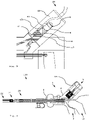
- FIG. 1 to 3 a first exemplary embodiment of a surgical instrument 100 with a connected cable 30, 40 is shown schematically.
- the surgical instrument comprises an exemplary embodiment of a connecting device 1 and an accessory 20.
- the accessory 20 here is an accessory that can be operated monopolarly and bipolarly. Of course, an accessory that can only be operated monopolarly or only bipolarly can also be connected to the surgical instrument 100 .
- the connecting device 1 is designed as a handle and comprises a housing 2 with a distal grip leg 3 (facing away from the user/surgeon or towards the body of a patient), an accessory coupling 4, an electrical connection element 5 with a first contact 6 and a second contact 7, a contact insulation 8, a first power line 9, a second power line 10, a line insulation 11, an actuating element 12, which as a proximal (facing the user/surgeon or the body a patient's handle arm is formed, and a gear 13.
- the accessory coupler 4 is located at a distal end of the connector. It is designed for the detachable mechanical and electrical connection of the accessory 20 to the connecting device 1 .
- the accessory coupling 4 is designed here, for example, as a spring-loaded ring in the radial direction, which can engage in a groove on the outer surface of a shank of a tool or can be engaged with it.
- the electrical connection element 5 is arranged at a proximal end of the connecting device 1 and is designed as a common plug.
- the common plug 5 here, for example, has a substantially cylindrical shape with a circular cross section and an outer surface that extends over the lateral surface of the cylindrical shape.
- the first contact 6 is arranged on the outer surface of the common plug 5 in a first, here proximal, area.
- the second contact 7 is arranged on the outer surface of the common plug 5 in a second, here distal area.
- the first contact 6 and the second contact 7 each have an electrical connection to the distal end of the common plug 5 .
- the first contact 6 and the second contact 7 and their electrical connections are electrically insulated from one another along the common plug 5 by the contact insulation 8 .
- the contact insulation 8 is designed such that in a monopolar or bipolar operation with an alternating current with a voltage of up to 5.5 kV no short circuit or voltage flashover between the first contact 6 and the second contact 7 (in bipolar operation) or between these and their surroundings (in monopolar and bipolar operation). In monopolar operation, the current can only flow from one or both of the contacts to a neutral electrode provided on the patient.
- a cable 30, 40 is electrically connected to the common plug 5 via a suitable connecting element 32, 42 on the connecting device side and mechanically connected in a detachable manner.
- the electrical connection element 32 , 42 on the connecting device side is designed as a matching common socket and is pushed onto the common plug 5 .
- the first power line 9 electrically connects the first contact 6 to a part of the accessory coupling 4 that can be moved via a gear rod 14 .
- a part of the first power line 9 is formed by the gear rod 14 of the gear 13 .
- the second power line 10 electrically connects the second contact 7 to a fixed part of the accessory coupling 4.
- a part of the second power line 10 is formed by a conductive sleeve 16 of the transmission 13.
- the first power line and the second power line are electrically insulated from one another and at least partially from their surroundings by the line insulation 11 .
- a part of the line insulation 11 is formed by a sliding sleeve 15 of the gear 13 .
- the line insulation 11 is designed in such a way that in monopolar or bipolar operation with an alternating current with a voltage of up to 5.5 kV, there is no short circuit or voltage flashover between the first power line 9 and the second power line 10 (in bipolar operation) or between these and their surroundings (in monopolar and bipolar operation).
- the actuating element 12 is designed as a proximal grip arm.
- the proximal handle limb 12 is rotatably mounted in the housing 2 and can be turned or rotated or pivoted relative to the distal handle limb 3 . A torque or a rotational movement can thus be transmitted to the gear mechanism 13 via the proximal grip arm 12 .
- the gear 13 comprises the gear rod 14 and a sliding sleeve 15 with a guide sleeve 16 arranged thereon.
- the gear rod 14 is mounted in the sliding sleeve 15 so that it can be displaced translationally in the direction of the accessory coupling 4 relative to the housing 2 .
- the gear rod 14 is mechanically connected to the proximal grip arm 12 via a sliding surface 17 at its proximal end.
- the transmission rod 14 extends to the accessory coupling 4 so that it can transmit a force or a translation to a mechanism (not shown here) of the coupled accessory 20 there.
- the sliding sleeve 15 provides the sliding bearing for the gear rod 14 relative to the housing 2 on the one hand and part of the cable insulation 11 on the other.
- the sliding sleeve 15 is surrounded by the guide sleeve 16 on its outer surface.
- the sliding sleeve 15 can be made of a plastic, in particular a friction-reducing and preferably steam-sterilizable plastic such as PEEK, polytetrafluoroethylene (PTFE) and the like can be made.
- the conductive sleeve 17 contains an electrically conductive material, preferably stainless steel, gold, platinum, copper, aluminum or the like, in particular stainless steel coated with gold. As a result, the gear rod 14 can be moved linearly with little sliding friction in the sliding sleeve 15 and is additionally electrically insulated from the second power line 10 or the electrically conductive conductive sleeve 17 .
- Torque or a rotational movement or rotation of the proximal grip arm 12 is transmitted to the gear rod 14 via the sliding surface 17 and converted into a translatory force or a translatory movement or translation.
- the transmission rod 14 transmits the force or translation to the mechanism of the attached accessory 20.
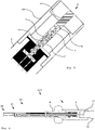
- In 2 is an enlarged section of the surgical instrument according to FIG 1 with a connected bipolar cable 30 shown schematically.
- the bipolar cable 30 is pushed onto the common plug 5 with an electrical connection element 32 on the connecting device side that is shaped as a common socket.
- the common connector 5 can also be of a Plug sleeve 18, not shown here for the sake of clarity (see figure 5 ) with a larger inner diameter than the connecting element 32, which protects the plug 5 and is designed to receive the connecting element 32 of the bipolar cable, which is shaped as a common socket.
- the common socket 32 has a bore in a substantially cylindrical shape with a circular cross-section, which is designed to accommodate the common plug 5 .
- the common socket 32 forms an interference fit or an interference fit with the common plug 5 so that there is sufficient static friction for the detachable mechanical connection between the two.
- the mechanical connection can be established between the common socket 32 and the common plug 5 via an O-ring or radially spring-loaded (snap) ring.
- a first cable contact 33 is arranged in a proximal region of the common socket 32 along the inner circumference of the bore.
- a second cable contact 34 is disposed in a distal portion of the common socket 32 along the inner circumference of the bore.
- a cable contact insulation 35 is arranged between the first cable contact 33 and the second cable contact 34 and electrically insulates the first cable contact 33 from the second cable contact 34 .
- the common socket 32 When the common socket 32 is pushed onto the common plug 5, there is a detachable mechanical connection between the bipolar cable 30 and the connecting device 1. Furthermore, the first cable contact 33 is exclusively on the first contact 6 and the second cable contact 34 exclusively to the second contact 7, so that there is an electrical connection between them.
- the surgical instrument 100 can be operated in a bipolar manner via the connected bipolar cable 30 .
- FIG 3 is an enlarged section of the surgical instrument of FIG 1 shown schematically with a connected monopolar cable 40 according to an embodiment. Only the differences to the bipolar cable 30 are explained below 2 explained. For the rest, the same applies as before with regard to 2 described.
- the monopolar cable 40 is pushed onto the common plug 5 with its electrical connection element 42 on the connecting device side, which is shaped as a common socket.
- the common bushing 42 has a bore in a substantially cylindrical shape with a circular cross-section.
- the common socket 42 forms an interference fit or an interference fit with the common plug 5 so that there is sufficient static friction for the detachable mechanical connection between the two.
- the mechanical connection can be established between the common socket 42 and the common plug 5 via an O-ring or radially spring-loaded (snap) ring.
- a first cable contact 43 is arranged in a proximal area of the common socket 42 along the inner circumference of the bore.
- a second cable contact 44 is disposed in a distal portion of the common socket 42 along the inner circumference of the bore.
- a Bridging 45 arranged between the first cable contact 43 and the second cable contact 44, which bridges the first cable contact 43 and the second cable contact 44 electrically.
- only a single elongate wire contact extending over the same area as the first and second wire contacts 43, 44 combined may be located in the bore.
- the surgical instrument 100 can be operated monopolarly via the connected monopolar cable 40 .
- FIG. 4 to 7 Another embodiment of the surgical instrument 100 according to the present invention is shown schematically, which is essentially the embodiment of FIG Figures 1 to 3 is equivalent to. There are only differences to the embodiment of the Figures 1 to 3 explained. Incidentally, the above apply to the Figures 1 to 3 according to the statements made.
- the common plug 5 also has a plug sleeve 18 which surrounds the cylindrical common plug 5 at a predefined radial distance.
- the plug sleeve 18 protects the common plug 5 from mechanical deformation and makes it easier to push on a common one Socket of a cable to the common connector 5 through their management properties.
- an O-ring or radially spring-loaded (snap) ring can be provided, which increases the friction between the common socket and the common plug 5 or the plug sleeve 18 .
- the accessory 20 is designed here as a clamp.
- the clamp 20 includes a mechanism 21 and a manipulator 22, which is formed here with two jaws.
- the clamping jaws can be rotated towards one another and away from one another via the mechanism 21 .
- the mechanism 21 is mechanically connected to the accessory coupling 4 with the gear 13 , in particular with the gear rod 14 .
- the gear rod 14 transmits a torque or a rotary movement as a translatory force or translation to the mechanism 21.
- the mechanism 21 converts the translatory force or translation into a torque or a rotary movement and transmits this(s) to the clamping jaws of the manipulator 22
- figure 5 is an enlarged section of the surgical instrument of FIG 4 shown schematically.
- the common connector 5 is here protected within the connector sleeve 18, which is mechanically connected to the housing 2 in a detachable or fixed manner.
- the connector sleeve 18 can also be designed integrally or in one piece with the housing 2 .
- a connector sleeve 18 on a gripping arm, preferably the non-movable gripping arm 3, would also be conceivable.
- In 6 is the surgical instrument of 4 in a to 4 vertical sectional plane shown schematically.
- Torque or a rotational movement of the proximal grip arm 12 is transmitted to the gear rod 14 on the sliding surface 17 .
- the torque or the rotational movement is converted into a translational force or translation.
- the monopolar cable 40 has instead of two cable contacts with bridging (cf. 3 ) has only a single elongated cable contact 46 in the electrical connection element 42 on the connecting device side, which is shaped as a common socket.
- the cable contact 42 electrically connects the first contact 6 and the second contact 7 and thus bridges them.
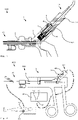
- the surgical system 200 includes the surgical instrument 100 according to FIG Figures 1 to 3 or 4 to 7 , the monopolar cable 40 according to 3 or 7 , a high-frequency generator (HF generator) 50 and a counter electrode or neutral electrode 60.
- HF generator high-frequency generator
- the monopolar cable 40 is connected to a monopolar output 51 of the HF generator 50 with an electrical connection element 41 on the generator side.
- the monopolar cable 40 is connected to the common plug 5 of the connecting device 1 of the surgical instrument 100 with the electrical connection element 42 on the connecting device side.
- the first contact and the second contact of the common plug 5 are bridged by bridging the monopolar cable 40 and electrically connected to one pole of the HF generator 50 .
- the accessory 20 of the surgical instrument 100 is mechanically and electrically connected to the connecting device 1 via the accessory coupling 4 of the connecting device 1 .
- the accessory 20 is electrically connected to one pole of the HF generator 50 via the connecting device 1 .
- the counter-electrode 60 is connected to a counter-electrode output 52 of the HF generator 52 via a monopolar cable and attached to a patient 70, for example in the form of an adhesive electrode.
- the counter-electrode 60 or the patient 70 is electrically connected to an opposite pole of the HF generator 50 .
- a surgeon can use the surgical instrument 100, which is operated monopolarly by the generator via the monopolar cable 40, to cut tissue in the patient 70 with monopolar alternating current between the accessory 20 and the counter electrode 60 (electrotomy) and at the same time or alternatively stop bleeding ( coagulation) .
- a bipolar cable can be pushed onto the common plug 5 with its electrical connection element on the connecting device side and connected with its electrical connection element on the generator side to a bipolar output of the HF generator 50 .
- bridging by a switchable bridging in the connecting device or in the HF generator can also be provided.
Landscapes
- Health & Medical Sciences (AREA)
- Surgery (AREA)
- Engineering & Computer Science (AREA)
- Life Sciences & Earth Sciences (AREA)
- Biomedical Technology (AREA)
- Otolaryngology (AREA)
- Nuclear Medicine, Radiotherapy & Molecular Imaging (AREA)
- Plasma & Fusion (AREA)
- Physics & Mathematics (AREA)
- Heart & Thoracic Surgery (AREA)
- Medical Informatics (AREA)
- Molecular Biology (AREA)
- Animal Behavior & Ethology (AREA)
- General Health & Medical Sciences (AREA)
- Public Health (AREA)
- Veterinary Medicine (AREA)
- Surgical Instruments (AREA)
Applications Claiming Priority (1)
| Application Number | Priority Date | Filing Date | Title |
|---|---|---|---|
| DE102020130716.0A DE102020130716A1 (de) | 2020-11-20 | 2020-11-20 | Verbindungsvorrichtung und monopolares Kabel für monopolar und bipolar betreibbare chirurgische Instrumente, chirurgisches Instrument und chirurgisches System |
Publications (1)
| Publication Number | Publication Date |
|---|---|
| EP4000548A1 true EP4000548A1 (fr) | 2022-05-25 |
Family
ID=78621798
Family Applications (1)
| Application Number | Title | Priority Date | Filing Date |
|---|---|---|---|
| EP21208237.4A Pending EP4000548A1 (fr) | 2020-11-20 | 2021-11-15 | Dispositif de connexion et câble monopolaire pour instruments chirurgicaux monopolaires et bipolaires, instrument chirurgical et système chirurgical |
Country Status (3)
| Country | Link |
|---|---|
| US (1) | US20220160420A1 (fr) |
| EP (1) | EP4000548A1 (fr) |
| DE (1) | DE102020130716A1 (fr) |
Families Citing this family (2)
| Publication number | Priority date | Publication date | Assignee | Title |
|---|---|---|---|---|
| DE102023102049A1 (de) | 2023-01-27 | 2024-08-01 | Joimax Gmbh | Bipolare Sonde, Sondensystem und Verfahren für einen elektrochirurgischen Eingriff |
| CN117064538B (zh) * | 2023-08-21 | 2024-02-13 | 江苏康进医疗器材有限公司 | 一种多功能高频切开刀 |
Citations (4)
| Publication number | Priority date | Publication date | Assignee | Title |
|---|---|---|---|---|
| EP0338105A1 (fr) * | 1988-04-20 | 1989-10-25 | Erbe Elektromedizin GmbH | Connecteur |
| US5573424A (en) * | 1995-02-09 | 1996-11-12 | Everest Medical Corporation | Apparatus for interfacing a bipolar electrosurgical instrument to a monopolar generator |
| DE20107483U1 (de) * | 2001-05-02 | 2002-01-03 | Olympus Winter & Ibe Gmbh, 22045 Hamburg | Bipolares endoskopisches Instrument |
| DE112017005056T5 (de) * | 2016-10-05 | 2019-06-13 | I.C. Medical, Inc. | Ultrapolare elektrochirurgische klinge und ultrapolarer elektrochirurgischer stift und teleskopischer elektrochirurgischer stift zur verwendung im monopolaren und bipolaren esu-modus |
Family Cites Families (2)
| Publication number | Priority date | Publication date | Assignee | Title |
|---|---|---|---|---|
| DE102009012431A1 (de) | 2009-03-10 | 2010-09-23 | Farin, Günter, Dipl.-Ing. | Verfahren und Einrichtung zum Betreiben einer HF-chirurgischen Anordnung |
| US20140276770A1 (en) | 2013-03-15 | 2014-09-18 | Alan G Ellman | Electrosurgical Handpiece |
-
2020
- 2020-11-20 DE DE102020130716.0A patent/DE102020130716A1/de active Pending
-
2021
- 2021-11-15 EP EP21208237.4A patent/EP4000548A1/fr active Pending
- 2021-11-19 US US17/531,604 patent/US20220160420A1/en active Pending
Patent Citations (4)
| Publication number | Priority date | Publication date | Assignee | Title |
|---|---|---|---|---|
| EP0338105A1 (fr) * | 1988-04-20 | 1989-10-25 | Erbe Elektromedizin GmbH | Connecteur |
| US5573424A (en) * | 1995-02-09 | 1996-11-12 | Everest Medical Corporation | Apparatus for interfacing a bipolar electrosurgical instrument to a monopolar generator |
| DE20107483U1 (de) * | 2001-05-02 | 2002-01-03 | Olympus Winter & Ibe Gmbh, 22045 Hamburg | Bipolares endoskopisches Instrument |
| DE112017005056T5 (de) * | 2016-10-05 | 2019-06-13 | I.C. Medical, Inc. | Ultrapolare elektrochirurgische klinge und ultrapolarer elektrochirurgischer stift und teleskopischer elektrochirurgischer stift zur verwendung im monopolaren und bipolaren esu-modus |
Also Published As
| Publication number | Publication date |
|---|---|
| DE102020130716A1 (de) | 2022-05-25 |
| US20220160420A1 (en) | 2022-05-26 |
Similar Documents
| Publication | Publication Date | Title |
|---|---|---|
| DE69803141T2 (de) | Verfahren und Einrichtung zur Versorgung von medizinischen Geräten mit elektrischer Energie | |
| EP1056409B1 (fr) | Instrument bipolaire a usage medical | |
| EP1392192B1 (fr) | Pince bipolaire | |
| DE60116147T2 (de) | Gefässverschliessende zange mit einmal-elektroden | |
| DE19729461C1 (de) | Bipolares endoskopisches Instrument | |
| EP4000548A1 (fr) | Dispositif de connexion et câble monopolaire pour instruments chirurgicaux monopolaires et bipolaires, instrument chirurgical et système chirurgical | |
| EP1211995A1 (fr) | Instrument medical bipolaire | |
| EP3033022B1 (fr) | Instrument chirurgical bipolaire comportant une poignée à usages multiples et outil à usage unique | |
| EP3132765B1 (fr) | Instrument de coagulation et de dissection a commande amelioree | |
| DE102008018614B4 (de) | Klemme für elektrochirurgische Anwendungen | |
| EP0596436A1 (fr) | Appareil électro-chirurgical | |
| DE102011107783B4 (de) | Bipolares Resektoskop sowie Schlitten und Kabel dafür | |
| DE10156917B4 (de) | Instrument für die endoskopische Chirurgie | |
| DE19641564C1 (de) | Chirurgische Vorrichtung | |
| DE10205093B4 (de) | Bipolare Klemme | |
| EP4046583A1 (fr) | Appareil électrochirurgical portatif et corps de contact pour appareils electrochirurgicaux portatifs | |
| DE102005004085B4 (de) | Doppelgelenkinstrument für chirurgische Anwendungen | |
| EP2298204B1 (fr) | Instrument médical pour l'électrochirurgie bipolaire | |
| DE102021132425B3 (de) | Handhabungsvorrichtung für ein elektrochirurgisches Instrument, Verfahren zur Herstellung einer Handhabungsvorrichtung und elektrochirurgisches Instrument | |
| DE102021108313A1 (de) | Elektrochirurgisches Handgerät sowie ein proximaler, mittlerer und distaler Abschnitt eines Hauptkörpers eines elektrochirurgischen Handgeräts | |
| DE102007001751B4 (de) | Elektrochirurgisches Verbindungsglied und elektrochirurgisches Instrument | |
| EP1771120B1 (fr) | Dispositif adaptateur | |
| DE102015004328B4 (de) | Transporteur und Stecker eines Resektoskopes | |
| WO1998053749A1 (fr) | Capot protecteur pour instruments hf medicaux | |
| DE102008044887A1 (de) | Bipolarelektrodeneinrichtung, Handgriff und bipolares System für elektrochirurgische Anwendungen |
Legal Events
| Date | Code | Title | Description |
|---|---|---|---|
| PUAI | Public reference made under article 153(3) epc to a published international application that has entered the european phase |
Free format text: ORIGINAL CODE: 0009012 |
|
| STAA | Information on the status of an ep patent application or granted ep patent |
Free format text: STATUS: THE APPLICATION HAS BEEN PUBLISHED |
|
| AK | Designated contracting states |
Kind code of ref document: A1 Designated state(s): AL AT BE BG CH CY CZ DE DK EE ES FI FR GB GR HR HU IE IS IT LI LT LU LV MC MK MT NL NO PL PT RO RS SE SI SK SM TR |
|
| STAA | Information on the status of an ep patent application or granted ep patent |
Free format text: STATUS: REQUEST FOR EXAMINATION WAS MADE |
|
| 17P | Request for examination filed |
Effective date: 20221114 |
|
| RBV | Designated contracting states (corrected) |
Designated state(s): AL AT BE BG CH CY CZ DE DK EE ES FI FR GB GR HR HU IE IS IT LI LT LU LV MC MK MT NL NO PL PT RO RS SE SI SK SM TR |
|
| P01 | Opt-out of the competence of the unified patent court (upc) registered |
Effective date: 20230527 |