EP4000548A1 - Connecting device and monopolar cable for monopolar and bipolar surgical instruments, surgical instrument and surgical system - Google Patents
Connecting device and monopolar cable for monopolar and bipolar surgical instruments, surgical instrument and surgical system Download PDFInfo
- Publication number
- EP4000548A1 EP4000548A1 EP21208237.4A EP21208237A EP4000548A1 EP 4000548 A1 EP4000548 A1 EP 4000548A1 EP 21208237 A EP21208237 A EP 21208237A EP 4000548 A1 EP4000548 A1 EP 4000548A1
- Authority
- EP
- European Patent Office
- Prior art keywords
- contact
- monopolar
- electrical connection
- connecting device
- cable
- Prior art date
- Legal status (The legal status is an assumption and is not a legal conclusion. Google has not performed a legal analysis and makes no representation as to the accuracy of the status listed.)
- Pending
Links
Images

Classifications
-
- A—HUMAN NECESSITIES
- A61—MEDICAL OR VETERINARY SCIENCE; HYGIENE
- A61B—DIAGNOSIS; SURGERY; IDENTIFICATION
- A61B18/00—Surgical instruments, devices or methods for transferring non-mechanical forms of energy to or from the body
- A61B18/04—Surgical instruments, devices or methods for transferring non-mechanical forms of energy to or from the body by heating
- A61B18/12—Surgical instruments, devices or methods for transferring non-mechanical forms of energy to or from the body by heating by passing a current through the tissue to be heated, e.g. high-frequency current
- A61B18/14—Probes or electrodes therefor
- A61B18/1442—Probes having pivoting end effectors, e.g. forceps
- A61B18/1445—Probes having pivoting end effectors, e.g. forceps at the distal end of a shaft, e.g. forceps or scissors at the end of a rigid rod
-
- A—HUMAN NECESSITIES
- A61—MEDICAL OR VETERINARY SCIENCE; HYGIENE
- A61B—DIAGNOSIS; SURGERY; IDENTIFICATION
- A61B18/00—Surgical instruments, devices or methods for transferring non-mechanical forms of energy to or from the body
- A61B18/04—Surgical instruments, devices or methods for transferring non-mechanical forms of energy to or from the body by heating
- A61B18/12—Surgical instruments, devices or methods for transferring non-mechanical forms of energy to or from the body by heating by passing a current through the tissue to be heated, e.g. high-frequency current
- A61B18/14—Probes or electrodes therefor
- A61B18/1402—Probes for open surgery
-
- A—HUMAN NECESSITIES
- A61—MEDICAL OR VETERINARY SCIENCE; HYGIENE
- A61B—DIAGNOSIS; SURGERY; IDENTIFICATION
- A61B18/00—Surgical instruments, devices or methods for transferring non-mechanical forms of energy to or from the body
- A61B18/04—Surgical instruments, devices or methods for transferring non-mechanical forms of energy to or from the body by heating
- A61B18/12—Surgical instruments, devices or methods for transferring non-mechanical forms of energy to or from the body by heating by passing a current through the tissue to be heated, e.g. high-frequency current
- A61B18/1206—Generators therefor
-
- A—HUMAN NECESSITIES
- A61—MEDICAL OR VETERINARY SCIENCE; HYGIENE
- A61B—DIAGNOSIS; SURGERY; IDENTIFICATION
- A61B18/00—Surgical instruments, devices or methods for transferring non-mechanical forms of energy to or from the body
- A61B18/04—Surgical instruments, devices or methods for transferring non-mechanical forms of energy to or from the body by heating
- A61B18/12—Surgical instruments, devices or methods for transferring non-mechanical forms of energy to or from the body by heating by passing a current through the tissue to be heated, e.g. high-frequency current
- A61B18/14—Probes or electrodes therefor
- A61B18/1442—Probes having pivoting end effectors, e.g. forceps
-
- A—HUMAN NECESSITIES
- A61—MEDICAL OR VETERINARY SCIENCE; HYGIENE
- A61B—DIAGNOSIS; SURGERY; IDENTIFICATION
- A61B17/00—Surgical instruments, devices or methods, e.g. tourniquets
- A61B2017/0046—Surgical instruments, devices or methods, e.g. tourniquets with a releasable handle; with handle and operating part separable
- A61B2017/00464—Surgical instruments, devices or methods, e.g. tourniquets with a releasable handle; with handle and operating part separable for use with different instruments
-
- A—HUMAN NECESSITIES
- A61—MEDICAL OR VETERINARY SCIENCE; HYGIENE
- A61B—DIAGNOSIS; SURGERY; IDENTIFICATION
- A61B17/00—Surgical instruments, devices or methods, e.g. tourniquets
- A61B2017/00477—Coupling
-
- A—HUMAN NECESSITIES
- A61—MEDICAL OR VETERINARY SCIENCE; HYGIENE
- A61B—DIAGNOSIS; SURGERY; IDENTIFICATION
- A61B18/00—Surgical instruments, devices or methods for transferring non-mechanical forms of energy to or from the body
- A61B2018/00053—Mechanical features of the instrument of device
- A61B2018/00059—Material properties
- A61B2018/00071—Electrical conductivity
- A61B2018/00077—Electrical conductivity high, i.e. electrically conducting
-
- A—HUMAN NECESSITIES
- A61—MEDICAL OR VETERINARY SCIENCE; HYGIENE
- A61B—DIAGNOSIS; SURGERY; IDENTIFICATION
- A61B18/00—Surgical instruments, devices or methods for transferring non-mechanical forms of energy to or from the body
- A61B2018/00053—Mechanical features of the instrument of device
- A61B2018/00059—Material properties
- A61B2018/00071—Electrical conductivity
- A61B2018/00083—Electrical conductivity low, i.e. electrically insulating
-
- A—HUMAN NECESSITIES
- A61—MEDICAL OR VETERINARY SCIENCE; HYGIENE
- A61B—DIAGNOSIS; SURGERY; IDENTIFICATION
- A61B18/00—Surgical instruments, devices or methods for transferring non-mechanical forms of energy to or from the body
- A61B2018/00053—Mechanical features of the instrument of device
- A61B2018/00172—Connectors and adapters therefor
- A61B2018/00178—Electrical connectors
-
- A—HUMAN NECESSITIES
- A61—MEDICAL OR VETERINARY SCIENCE; HYGIENE
- A61B—DIAGNOSIS; SURGERY; IDENTIFICATION
- A61B18/00—Surgical instruments, devices or methods for transferring non-mechanical forms of energy to or from the body
- A61B2018/00571—Surgical instruments, devices or methods for transferring non-mechanical forms of energy to or from the body for achieving a particular surgical effect
- A61B2018/00589—Coagulation
-
- A—HUMAN NECESSITIES
- A61—MEDICAL OR VETERINARY SCIENCE; HYGIENE
- A61B—DIAGNOSIS; SURGERY; IDENTIFICATION
- A61B18/00—Surgical instruments, devices or methods for transferring non-mechanical forms of energy to or from the body
- A61B2018/00571—Surgical instruments, devices or methods for transferring non-mechanical forms of energy to or from the body for achieving a particular surgical effect
- A61B2018/00595—Cauterization
-
- A—HUMAN NECESSITIES
- A61—MEDICAL OR VETERINARY SCIENCE; HYGIENE
- A61B—DIAGNOSIS; SURGERY; IDENTIFICATION
- A61B18/00—Surgical instruments, devices or methods for transferring non-mechanical forms of energy to or from the body
- A61B2018/00571—Surgical instruments, devices or methods for transferring non-mechanical forms of energy to or from the body for achieving a particular surgical effect
- A61B2018/00607—Coagulation and cutting with the same instrument
-
- A—HUMAN NECESSITIES
- A61—MEDICAL OR VETERINARY SCIENCE; HYGIENE
- A61B—DIAGNOSIS; SURGERY; IDENTIFICATION
- A61B18/00—Surgical instruments, devices or methods for transferring non-mechanical forms of energy to or from the body
- A61B2018/0091—Handpieces of the surgical instrument or device
-
- A—HUMAN NECESSITIES
- A61—MEDICAL OR VETERINARY SCIENCE; HYGIENE
- A61B—DIAGNOSIS; SURGERY; IDENTIFICATION
- A61B18/00—Surgical instruments, devices or methods for transferring non-mechanical forms of energy to or from the body
- A61B18/04—Surgical instruments, devices or methods for transferring non-mechanical forms of energy to or from the body by heating
- A61B18/12—Surgical instruments, devices or methods for transferring non-mechanical forms of energy to or from the body by heating by passing a current through the tissue to be heated, e.g. high-frequency current
- A61B18/1206—Generators therefor
- A61B2018/1246—Generators therefor characterised by the output polarity
- A61B2018/1253—Generators therefor characterised by the output polarity monopolar
-
- A—HUMAN NECESSITIES
- A61—MEDICAL OR VETERINARY SCIENCE; HYGIENE
- A61B—DIAGNOSIS; SURGERY; IDENTIFICATION
- A61B18/00—Surgical instruments, devices or methods for transferring non-mechanical forms of energy to or from the body
- A61B18/04—Surgical instruments, devices or methods for transferring non-mechanical forms of energy to or from the body by heating
- A61B18/12—Surgical instruments, devices or methods for transferring non-mechanical forms of energy to or from the body by heating by passing a current through the tissue to be heated, e.g. high-frequency current
- A61B18/1206—Generators therefor
- A61B2018/1246—Generators therefor characterised by the output polarity
- A61B2018/126—Generators therefor characterised by the output polarity bipolar
-
- A—HUMAN NECESSITIES
- A61—MEDICAL OR VETERINARY SCIENCE; HYGIENE
- A61B—DIAGNOSIS; SURGERY; IDENTIFICATION
- A61B18/00—Surgical instruments, devices or methods for transferring non-mechanical forms of energy to or from the body
- A61B18/04—Surgical instruments, devices or methods for transferring non-mechanical forms of energy to or from the body by heating
- A61B18/12—Surgical instruments, devices or methods for transferring non-mechanical forms of energy to or from the body by heating by passing a current through the tissue to be heated, e.g. high-frequency current
- A61B18/14—Probes or electrodes therefor
- A61B18/1442—Probes having pivoting end effectors, e.g. forceps
- A61B2018/146—Scissors
-
- A—HUMAN NECESSITIES
- A61—MEDICAL OR VETERINARY SCIENCE; HYGIENE
- A61B—DIAGNOSIS; SURGERY; IDENTIFICATION
- A61B18/00—Surgical instruments, devices or methods for transferring non-mechanical forms of energy to or from the body
- A61B18/04—Surgical instruments, devices or methods for transferring non-mechanical forms of energy to or from the body by heating
- A61B18/12—Surgical instruments, devices or methods for transferring non-mechanical forms of energy to or from the body by heating by passing a current through the tissue to be heated, e.g. high-frequency current
- A61B18/14—Probes or electrodes therefor
- A61B18/1442—Probes having pivoting end effectors, e.g. forceps
- A61B2018/1462—Tweezers
Definitions
- the present invention relates to a connecting device for surgical instruments that can be operated monopolarly and bipolarly, in particular for high-frequency surgery (HF surgery), and an associated monopolar cable, as well as a corresponding surgical instrument that can be operated monopolarly and bipolarly, and a corresponding surgical system.
- HF surgery high-frequency surgery
- a corresponding surgical instrument that can be operated monopolarly and bipolarly, and a corresponding surgical system.
- Surgical instruments often have a connecting device, in particular a handle or a robot interface, and a tool that can be attached to it by means of an accessory coupling, usually referred to as an accessory, for example scissors, clamps or the like.
- an accessory for example scissors, clamps or the like.
- the thermal effect of high-frequency alternating current on tissue is used in so-called electrotomy (also diathermy or electrocaustic) and coagulation (clotting) in order to cut through target tissue and, if necessary, to stop bleeding at the same time or instead.
- the surgical instruments have one or more (active) electrodes on their accessories (eg clamps, scissors or the like), via which the high-frequency alternating current is introduced into the target tissue of a patient becomes.
- a high current density is applied to the target tissue.
- (active) electrodes generally have a small surface area and are designed, for example, in the form of needles or blades in order to introduce the applied high-frequency alternating current into the target tissue with the highest possible current density.
- Either monopolar or bipolar operated surgical instruments can be used.
- a single active electrode is arranged on the accessory of the surgical instrument, via which the high-frequency alternating current is introduced into the tissue of a patient. So that the current can be introduced into the tissue from the individual active electrodes, a large counter-electrode (neutral electrode) must be attached to the patient's body as the opposite pole.
- two electrodes active electrode and neutral electrode
- the high-frequency alternating current is introduced into the target tissue from a first electrode (active electrode) directly opposite the second electrode (neutral electrode).
- plugs and sockets on the handles and cables are usually each shape-coded so that monopolar cables only fit on handles of monopolar-operated surgical instruments and bipolar cables only on handles of bipolar-operated surgical instruments instruments can be connected.
- the present invention is based on the object of providing an improved connection device that can in particular be used more flexibly, as well as a monopolar cable for surgical instruments that can be operated monopolarly and bipolarly.
- this object is achieved by a connecting device having the features of independent patent claim 1 and a monopolar cable, a surgical instrument and a surgical system having the features of the other independent patent claims.
- a connecting device for surgical instruments that can be operated monopolarly and bipolarly, in particular for high-frequency surgery, comprises a housing, an accessory coupling and an electrical connection.
- the accessory coupler is located on the housing.
- the accessory coupling is designed for the mechanical and electrical coupling of an accessory that can be operated in a monopolar manner and additionally or alternatively in a bipolar manner.
- the electrical connection is arranged on the housing.
- the electrical connection has a first contact and a second contact.
- the electrical connection can be connected either to a monopolar cable (for monopolar operation) or to a bipolar cable (for bipolar operation).
- the first contact and the second contact are electrically connected to the accessory coupling and are insulated in such a way that an accessory coupled to the accessory coupling can be operated either monopolarly or bipolarly via the two contacts.
- the idea on which the present invention is based is to use the two sufficiently insulated contacts and electrical connections of these two contacts with the accessory coupling to provide a surgical device equipped with the connecting device according to the invention Design the instrument to be operated in either a monopolar or bipolar manner.
- the surgical instrument which can be operated monopolarly and bipolarly, is used in surgical interventions.
- tissue can be severed (electrotomy) and bleeding can be additionally or alternatively stopped (coagulation) with the surgical instrument, which can be operated either monopolarly or bipolarly.
- the surgical instrument that can be operated monopolarly and bipolarly can be, for example, an instrument guided by a user or operator (eg surgeon) by hand or by a robot (arm).
- the connecting device is designed in such a way that an accessory mechanically connected to it can be guided.
- a guide element designed as a handle can be held in the hand of a user (eg a surgeon) and a mechanically connected accessory can thus be guided by hand.
- a connecting device designed as a manipulator coupling or robot mount can be connected to a surgical robot and a mechanically connected accessory can thus be guided through the surgical robot.
- the housing can be designed integrally or in one piece, or it can be formed from a number of components (e.g. shell elements) which are mechanically connected to one another in a detachable or fixed manner.
- the housing can be made at least partially from a plastic, a metal or an alloy.
- the housing can preferably be made at least partially from a biocompatible material.
- the housing can be used with the accessory coupling be detachably or firmly mechanically connected.
- the housing can accommodate the accessory coupler.
- the housing may include or be integrally formed with the accessory coupler.
- the housing can be mechanically connected to the electrical connection in a detachable or fixed manner.
- the housing can accommodate the electrical connection.
- the housing can comprise the electrical connection or be formed integrally therewith.
- the accessory coupling is designed in such a way that the accessory (e.g. scissors, clamps or the like) that can be operated monopolarly and additionally or alternatively bipolarly can be detachably mechanically connected to the housing (mechanical coupling).
- the accessory coupling can be designed as an internal thread, external thread, bayonet adapter (bayonet lock), snap element (snap connection), in particular a radially spring-loaded ring, or the like, which can be mechanically releasably connected to a suitable counterpart on a proximal end of the accessory.
- the accessory coupling is designed in such a way that there is an electrical connection (electrical coupling) between the detachably mechanically connected accessory and the accessory coupling.
- the electrical connection can be realized via a plug-socket connection, contact plates, sliding contacts and the like.
- the accessory is electrically connected to the first contact and the second contact of the electrical connection via the electrical coupling.
- suitable lines can run from the accessory coupling inside or outside along the housing to the electrical connection and electrically connect them to one another.
- the electrical connection is designed in such a way that the monopolar or the bipolar cable can be connected to it using a suitable electrical connection element (on the connecting device side).
- the monopolar/bipolar cable can be releasably mechanically connected to the electrical connection on the one hand and electrically to the first contact and additionally or alternatively to the second contact on the other hand via its suitable electrical connection element, in particular on the connection device side.
- the electrical connection can be in the form of a plug, socket, internal thread, external thread, bayonet adapter, snap-on element, in particular a radially spring-loaded ring, or the like with an integrated first and second contact.
- the electrical connection includes the first and second contacts.
- the first and additionally or alternatively the second contact can be made at least partially from an electrically conductive material, preferably stainless steel, gold, platinum, copper, aluminum, tungsten or the like and combinations thereof.
- the first and additionally or alternatively the second contact can be made of stainless steel with a gold coating.
- one pole of a monopolar cable can be electrically connected to the electrical connection via the first contact and additionally or alternatively via the second contact.
- the two poles of a bipolar cable can be electrically connected to the electrical connection via the first contact and the second contact.
- the one pole or the two poles of the monopolar/bipolar Cables may be electrically connected to the accessory coupler via the appropriate leads.
- the first electrical contact and the second electrical contact are insulated in such a way that both in bipolar operation with two different poles that are electrically connected to the first and second contact, and in monopolar operation with a single pole that is connected to the first contact and is additionally or alternatively electrically connected to the second contact, no electric current can flow between the two contacts and between one of the contacts and its surroundings.
- the first and the second contact are preferably insulated in such a way that in monopolar operation a voltage of 0 V [volt] to 5500 V and in bipolar operation a voltage of 0 V to 1000 V, more preferably in monopolar operation a voltage of 0 V to 4300 V and in bipolar operation a voltage of 0 V to 250 V and particularly preferably in monopolar operation a voltage of 0 V to 3000 V and in bipolar operation a voltage of 0 V to 190 V can be applied without causing a short circuit or voltage flashover occurs. Furthermore, the voltage security can be guaranteed to a much higher degree, in particular with values whose use is permitted for the respective user.
- the connecting device With the connecting device according to the invention, it is possible to switch quickly and with little effort between an accessory that can be operated in a monopolar manner and an accessory that can be operated in a bipolar manner or between monopolar operation and bipolar operation. There is no need to switch between a connection device for monopolar operation and one for bipolar operation.
- the user e.g. surgeon
- contact insulation is provided for electrically isolating the first contact and the second contact from one another.
- the contact insulation electrically isolates the first contact from the second contact.
- the contact insulation insulates the first and the second contact from their surroundings. Only in a respectively predefined area are the first contact and the second contact not electrically isolated from their surroundings, so that the electrical connection with the monopolar or bipolar cable or with one pole or both poles thereof can be established there.
- the contact insulation can be made at least partially from a plastic or a ceramic.
- the contact insulation is formed by at least one tube, in particular a shrink tube. Additionally or alternatively, the contact insulation can be formed by at least one coating. Additionally or alternatively, the line insulation can be formed by at least one tube made of polyetheretherketone (PEEK). be.
- PEEK polyetheretherketone
- a first power line for electrically connecting the first contact and a second power line for electrically connecting the second contact to the accessory coupling are arranged in or on the housing. Wire insulation is provided for electrically isolating the first power line and the second power line from each other and from their surroundings.
- the first power line connects the first contact of the electrical connector to the accessory coupler.
- one pole of a monopolar or bipolar cable connected to the electrical connection can be electrically connected to the monopolar or bipolar operable accessory that is coupled to the accessory coupling.
- the second power line connects the second contact of the electrical connector to the accessory coupler.
- the same or another pole of a monopolar or bipolar cable connected to the electrical connection can be electrically connected to the monopolar or bipolar operable accessory that is coupled to the accessory coupling.
- the first and additionally or alternatively the second power line can be at least partially made of an electrically conductive material, preferably stainless steel, gold, platinum, copper, Aluminum, tungsten or the like and combinations thereof.
- the first and additionally or alternatively the second power line can be made of stainless steel with a gold coating.
- the wire insulation electrically insulates the first power line from the second power line.
- the line insulation insulates the first and second power lines from their surroundings. In one embodiment, this corresponds to shaft insulation from the outside. In particular, insulation between the poles has no insulating effect to the outside.
- the line insulation can be made at least partially from a plastic or a ceramic.
- the line insulation is formed by at least one tube, in particular a shrink tube. Additionally or alternatively, the line insulation is formed by at least one coating. Additionally or alternatively, the line insulation is formed by at least one tube, which contains in particular plastic, preferably PEEK. The line insulation encloses the first power line and additionally or alternatively the second power line.
- the cable insulation enables the surgical instrument to be operated in either monopolar or bipolar mode, since a short circuit is effectively prevented in both operating modes.
- a short circuit between the first and second power lines in bipolar operation and between the first and second power lines and their surroundings in monopolar and bipolar operation is effectively prevented. This is advantageously ensured in particular in the case of a neutral electrode provided on the patient during operation.
- the contact insulation and additionally or alternatively the line insulation has an insulation section designed for alternating currents in monopolar operation, preferably for coagulation and additionally or alternatively electrotomy.
- the contact insulation and additionally or alternatively the line insulation is designed in such a way that no measurable current occurs during monopolar operation with alternating current, in particular with a voltage of 0 V to 5500 V, preferably from 0 V to 4300 V and particularly preferably from 0 V to 3000 V flows between the first contact and the second contact and between these and their surroundings or between the first power line and the second power line and between these and their surroundings.
- the contact insulation and additionally or alternatively the line insulation is designed in such a way that, in monopolar operation with alternating current, in particular with a voltage of 0 V to 5500 V, preferably from 0 V to 4300 V and particularly preferably from 0 V to 3000 V, no measurable Leakage current flows on its surface. An undesired short circuit or voltage flashover can thus be prevented in a particularly reliable manner both in the case of bipolar and in the case of monopolar operation of the surgical instrument.
- the electrical connection is designed for selectively connecting the first contact and the second contact to a monopolar cable or to a bipolar cable via a common plug.
- the common connector allows one pole of the monopolar cable or the two poles of the bipolar cable to be contacted with the first contact and the second contact via a single element, for example a pin.
- the mechanical connection between the electrical connection of the connecting device and the suitable electrical connection element of the monopolar or bipolar cable on the connecting device side is produced by static friction through the common plug.
- the static friction is adjusted by means of a transition fit or an oversize fit, with the static friction also being able to be adjusted via elastic elements.
- the mechanical connection can be made by means of a ball catch, a snap ring or the like.
- the mechanical and the electrical connection between the electrical connection and the suitable electrical connection element on the connection device side can be established in a particularly simple manner through the common plug.
- the electrical connection is designed as the common plug.
- the common plug On its outer surface along its longitudinal direction, the common plug has the first contact in a first contact area, the contact insulation in an insulation area and the second contact in a second contact area.
- the electrical connection of the connecting device designed as the common plug can electrically contact either one pole of the monopolar cable or one of the two poles of the bipolar cable in the first contact area.
- In the second contact area can accordingly either also one pole of the monopolar cable or the other of the two poles of the bipolar cable are electrically contacted.
- the electrical connection designed as the common plug can be cleaned and sterilized particularly easily after a surgical intervention together with or separately from the connecting device.
- the electrical connection is designed as a common socket.
- the common socket has on its inner surface along its longitudinal direction in a first contact area the first contact in an insulation area the contact insulation and in a second contact area the second contact.
- the electrical connection of the connecting device designed as the common socket can electrically contact either one pole of the monopolar cable or one of the two poles of the bipolar cable in the first contact area.
- either one pole of the monopolar cable or the other of the two poles of the bipolar cable can also be electrically contacted.
- the electrical connection designed as the common socket is particularly protected against mechanical deformation, since no contact element (e.g. pin) protrudes outwards and therefore cannot be accidentally bent.
- no contact element e.g. pin
- an actuating element is also arranged on the housing.
- a gear is arranged in or on the housing.
- the transmission is mechanically coupled to the actuator.
- the transmission is designed to transmit a movement of the actuating element to a mechanism of an accessory that can be mechanically connected via the accessory coupling, in particular with a predetermined transmission ratio.
- the housing can be mechanically connected to the actuating element in a detachable or non-detachable manner, with the actuating element being mounted such that it can be displaced or rotated relative to the housing in at least one translational and additionally or alternatively rotational degree of freedom.
- the transmission is movably mounted in an interior of the housing or on its outside in such a way that displacement or rotation in at least one translational and additionally or alternatively rotational degree of freedom relative to the housing is possible.
- the actuating element is used to introduce force or torque and to transmit force or torque from the outside.
- the actuating element can be designed, for example, as a manual actuation, via which a user or operator (e.g. surgeon) can manually apply a force to actuate an accessory, or as an actuating coupling for a robot (arm).
- the transmission is mechanically connected to the actuating element and absorbs the force or torque introduced from the outside via the actuating element and passes this on to the mechanism of the connected accessory in the area of the accessory coupling.
- One of them can Actuator introduced force can be converted into a torque or torque introduced into a force. A rotation can therefore be converted into a translation and vice versa.
- the transmission can also be used to implement a transmission with a predefined transmission ratio between the actuating element and the mechanism of the connected accessory or a manipulator of the accessory that is actuated via the mechanism of the accessory.
- the actuating element can be designed as a rotatable scissor handle and the gear as a gear rod, which is mounted in a sliding sleeve in the housing in a translationally displaceable manner.
- the scissors handle can rest against a correspondingly shaped sliding surface on a proximal end of the gear rod, so that a rotational movement of the scissors handle is transmitted to the gear rod and converted into a translation.
- Various accessories with various manipulators can be coupled to and actuated via the connecting device via the actuating element and the gearing.
- the transmission is designed to be at least partially electrically conductive.
- the transmission at least partially forms either the first power line and additionally or alternatively the second power line.
- the first contact and additionally or alternatively the second contact of the electrical connection are electrically connected to the accessory coupling via the transmission.
- the gear mechanism designed as a gear rod mounted in the sliding sleeve can at least partially form the first power line via said gear rod.
- the gear rod is electrically connected to the first contact of the electrical connection via a sliding contact.
- the sliding sleeve can be at least part of the cable insulation, z. B. in the form of a sleeve made of polytetrafluoroethylene (PTFE), and at the same time at least partially form the second power line.
- a line sleeve can be arranged around the (inner) part of the sliding sleeve that forms the line insulation, which sleeve is electrically connected to the second contact of the electrical connection.
- connection device can be made in a very efficient and simple way with particularly few elements.
- the accessory coupling is designed for the mechanical and electrical coupling of an accessory designed as a clamp or scissors.
- the contact insulation and additionally or alternatively the line insulation each have an insulation gap which is suitable for alternating currents with a voltage of up to 5.5 kV [kilovolt], preferably up to 4.3 kV and particularly preferably up to 3 .0 kV is designed.
- a monopolar cable for surgical instruments that can be operated monopolarly and bipolarly, in particular for high-frequency surgery, comprises an electrical connection element on the generator side, an electrical connection element on the connection device side, and a jumper.
- the electrical connection element on the generator side is designed for connection to a monopolar output of a high-frequency alternating current generator.
- the electrical connection element on the connection device side is designed for connection to an electrical connection of a connection device according to the invention as described above.
- the bridging is designed to electrically bridge the first electrical contact and the second electrical contact of the electrical connection.
- the electrical connection element on the generator side is designed to produce a mechanical, for example frictional, and electrical connection to the monopolar output of the generator.
- the electrical connection element on the connection device side is designed to establish a mechanical, for example frictional and electrical connection with the electrical connection of the connection device.
- the electrical connection element on the connecting device side can be embodied as a common socket, which can be pushed onto the electrical connection embodied as a common plug.
- the electrical connection element on the connecting device side can be designed as a common plug, which can be plugged into the electrical connection designed as a common socket.
- the bridging connects one pole of the monopolar output of the generator to both contacts of the electrical connection of the connecting device.
- the bridging bridges the contacts of the electrical connection of the connecting device, which contacts are designed to be insulated from one another (via the contact insulation).
- a surgical instrument that can be operated monopolarly and bipolarly, which includes the connecting device according to the invention, can be operated monopolarly.
- the monopolar cable instead of a bipolar cable, the monopolar cable only needs to be connected to the electrical connection of the connection device according to the invention and connected to the monopolar output of the generator. A complex change of instruments during a surgical intervention can thus advantageously be avoided.
- the bridging is either in the generator-side electrical connection element, the connecting device-side electrical connection element or in a region along the monopolar cable between the generator-side electrical connection element and the electrical connection element on the connection device side.
- the bridging is formed in the generator-side electrical connection element, then two electrical lines are electrically connected to the bridging.
- the two electrical lines run, insulated from one another, along the monopolar cable up to the electrical connection element on the connecting device side.
- the electrical connection element on the connection device makes electrical contact with the first and the second contact of the electrical connection of the connection device separately from one another.
- an electrical line is electrically connected along the monopolar cable from the generator-side electrical connection element to the bridging and two electrical lines are electrically connected from the bridging to the connecting device-side electrical connection element.
- the two electrical lines are isolated from each other.
- the electrical connection element on the connection device makes electrical contact with the first and the second contact of the electrical connection of the connection device separately from one another.
- the bridging is preferably formed in the electrical connection element on the connection device side.
- An electrical line runs along the monopolar cable from the electrical connection element on the generator side to the electrical connection element on the connection device side.
- the electrical connection element on the connection device side makes contact with the first and the second contact of the electrical connection of the connecting device electrically in common.
- the monopolar cable with bridging according to the invention in particular in the connector-side electrical connection element, securely connects the first contact and the second contact to one pole of the monopolar output of the generator.
- a surgical instrument in particular for high-frequency surgery, comprises a connection device according to the invention as described above and an accessory that can be operated monopolarly and additionally or alternatively in a bipolar manner.
- the monopolar and additionally or alternatively bipolar operable accessory is electrically and mechanically coupled to the connecting device via the accessory coupling of the connecting device.
- the connecting device is designed as a handle, in particular as a movable handle with an actuating element for actuating an accessory coupled thereto, which is preferably designed as a clamp or scissors.
- a surgical system in particular for high-frequency surgery, comprising a surgical instrument according to the invention as described above, a high-frequency generator (HF generator) and a monopolar cable according to the invention as described above.
- the HF generator has at least one monopolar output.
- the monopolar cable is connected with the electrical connection element on the connection device side to the electrical connection of the connection device of the surgical instrument and with the electrical connection element on the generator side to the monopolar output of the HF generator.
- the accessory of the surgical instrument is monopolarly connected to the monopolar output of the HF generator via the connecting device and the connected monopolar cable.
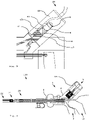
- FIG. 1 to 3 a first exemplary embodiment of a surgical instrument 100 with a connected cable 30, 40 is shown schematically.
- the surgical instrument comprises an exemplary embodiment of a connecting device 1 and an accessory 20.
- the accessory 20 here is an accessory that can be operated monopolarly and bipolarly. Of course, an accessory that can only be operated monopolarly or only bipolarly can also be connected to the surgical instrument 100 .
- the connecting device 1 is designed as a handle and comprises a housing 2 with a distal grip leg 3 (facing away from the user/surgeon or towards the body of a patient), an accessory coupling 4, an electrical connection element 5 with a first contact 6 and a second contact 7, a contact insulation 8, a first power line 9, a second power line 10, a line insulation 11, an actuating element 12, which as a proximal (facing the user/surgeon or the body a patient's handle arm is formed, and a gear 13.
- the accessory coupler 4 is located at a distal end of the connector. It is designed for the detachable mechanical and electrical connection of the accessory 20 to the connecting device 1 .
- the accessory coupling 4 is designed here, for example, as a spring-loaded ring in the radial direction, which can engage in a groove on the outer surface of a shank of a tool or can be engaged with it.
- the electrical connection element 5 is arranged at a proximal end of the connecting device 1 and is designed as a common plug.
- the common plug 5 here, for example, has a substantially cylindrical shape with a circular cross section and an outer surface that extends over the lateral surface of the cylindrical shape.
- the first contact 6 is arranged on the outer surface of the common plug 5 in a first, here proximal, area.
- the second contact 7 is arranged on the outer surface of the common plug 5 in a second, here distal area.
- the first contact 6 and the second contact 7 each have an electrical connection to the distal end of the common plug 5 .
- the first contact 6 and the second contact 7 and their electrical connections are electrically insulated from one another along the common plug 5 by the contact insulation 8 .
- the contact insulation 8 is designed such that in a monopolar or bipolar operation with an alternating current with a voltage of up to 5.5 kV no short circuit or voltage flashover between the first contact 6 and the second contact 7 (in bipolar operation) or between these and their surroundings (in monopolar and bipolar operation). In monopolar operation, the current can only flow from one or both of the contacts to a neutral electrode provided on the patient.
- a cable 30, 40 is electrically connected to the common plug 5 via a suitable connecting element 32, 42 on the connecting device side and mechanically connected in a detachable manner.
- the electrical connection element 32 , 42 on the connecting device side is designed as a matching common socket and is pushed onto the common plug 5 .
- the first power line 9 electrically connects the first contact 6 to a part of the accessory coupling 4 that can be moved via a gear rod 14 .
- a part of the first power line 9 is formed by the gear rod 14 of the gear 13 .
- the second power line 10 electrically connects the second contact 7 to a fixed part of the accessory coupling 4.
- a part of the second power line 10 is formed by a conductive sleeve 16 of the transmission 13.
- the first power line and the second power line are electrically insulated from one another and at least partially from their surroundings by the line insulation 11 .
- a part of the line insulation 11 is formed by a sliding sleeve 15 of the gear 13 .
- the line insulation 11 is designed in such a way that in monopolar or bipolar operation with an alternating current with a voltage of up to 5.5 kV, there is no short circuit or voltage flashover between the first power line 9 and the second power line 10 (in bipolar operation) or between these and their surroundings (in monopolar and bipolar operation).
- the actuating element 12 is designed as a proximal grip arm.
- the proximal handle limb 12 is rotatably mounted in the housing 2 and can be turned or rotated or pivoted relative to the distal handle limb 3 . A torque or a rotational movement can thus be transmitted to the gear mechanism 13 via the proximal grip arm 12 .
- the gear 13 comprises the gear rod 14 and a sliding sleeve 15 with a guide sleeve 16 arranged thereon.
- the gear rod 14 is mounted in the sliding sleeve 15 so that it can be displaced translationally in the direction of the accessory coupling 4 relative to the housing 2 .
- the gear rod 14 is mechanically connected to the proximal grip arm 12 via a sliding surface 17 at its proximal end.
- the transmission rod 14 extends to the accessory coupling 4 so that it can transmit a force or a translation to a mechanism (not shown here) of the coupled accessory 20 there.
- the sliding sleeve 15 provides the sliding bearing for the gear rod 14 relative to the housing 2 on the one hand and part of the cable insulation 11 on the other.
- the sliding sleeve 15 is surrounded by the guide sleeve 16 on its outer surface.
- the sliding sleeve 15 can be made of a plastic, in particular a friction-reducing and preferably steam-sterilizable plastic such as PEEK, polytetrafluoroethylene (PTFE) and the like can be made.
- the conductive sleeve 17 contains an electrically conductive material, preferably stainless steel, gold, platinum, copper, aluminum or the like, in particular stainless steel coated with gold. As a result, the gear rod 14 can be moved linearly with little sliding friction in the sliding sleeve 15 and is additionally electrically insulated from the second power line 10 or the electrically conductive conductive sleeve 17 .
- Torque or a rotational movement or rotation of the proximal grip arm 12 is transmitted to the gear rod 14 via the sliding surface 17 and converted into a translatory force or a translatory movement or translation.
- the transmission rod 14 transmits the force or translation to the mechanism of the attached accessory 20.
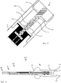
- In 2 is an enlarged section of the surgical instrument according to FIG 1 with a connected bipolar cable 30 shown schematically.
- the bipolar cable 30 is pushed onto the common plug 5 with an electrical connection element 32 on the connecting device side that is shaped as a common socket.
- the common connector 5 can also be of a Plug sleeve 18, not shown here for the sake of clarity (see figure 5 ) with a larger inner diameter than the connecting element 32, which protects the plug 5 and is designed to receive the connecting element 32 of the bipolar cable, which is shaped as a common socket.
- the common socket 32 has a bore in a substantially cylindrical shape with a circular cross-section, which is designed to accommodate the common plug 5 .
- the common socket 32 forms an interference fit or an interference fit with the common plug 5 so that there is sufficient static friction for the detachable mechanical connection between the two.
- the mechanical connection can be established between the common socket 32 and the common plug 5 via an O-ring or radially spring-loaded (snap) ring.
- a first cable contact 33 is arranged in a proximal region of the common socket 32 along the inner circumference of the bore.
- a second cable contact 34 is disposed in a distal portion of the common socket 32 along the inner circumference of the bore.
- a cable contact insulation 35 is arranged between the first cable contact 33 and the second cable contact 34 and electrically insulates the first cable contact 33 from the second cable contact 34 .
- the common socket 32 When the common socket 32 is pushed onto the common plug 5, there is a detachable mechanical connection between the bipolar cable 30 and the connecting device 1. Furthermore, the first cable contact 33 is exclusively on the first contact 6 and the second cable contact 34 exclusively to the second contact 7, so that there is an electrical connection between them.
- the surgical instrument 100 can be operated in a bipolar manner via the connected bipolar cable 30 .
- FIG 3 is an enlarged section of the surgical instrument of FIG 1 shown schematically with a connected monopolar cable 40 according to an embodiment. Only the differences to the bipolar cable 30 are explained below 2 explained. For the rest, the same applies as before with regard to 2 described.
- the monopolar cable 40 is pushed onto the common plug 5 with its electrical connection element 42 on the connecting device side, which is shaped as a common socket.
- the common bushing 42 has a bore in a substantially cylindrical shape with a circular cross-section.
- the common socket 42 forms an interference fit or an interference fit with the common plug 5 so that there is sufficient static friction for the detachable mechanical connection between the two.
- the mechanical connection can be established between the common socket 42 and the common plug 5 via an O-ring or radially spring-loaded (snap) ring.
- a first cable contact 43 is arranged in a proximal area of the common socket 42 along the inner circumference of the bore.
- a second cable contact 44 is disposed in a distal portion of the common socket 42 along the inner circumference of the bore.
- a Bridging 45 arranged between the first cable contact 43 and the second cable contact 44, which bridges the first cable contact 43 and the second cable contact 44 electrically.
- only a single elongate wire contact extending over the same area as the first and second wire contacts 43, 44 combined may be located in the bore.
- the surgical instrument 100 can be operated monopolarly via the connected monopolar cable 40 .
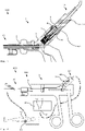
- FIG. 4 to 7 Another embodiment of the surgical instrument 100 according to the present invention is shown schematically, which is essentially the embodiment of FIG Figures 1 to 3 is equivalent to. There are only differences to the embodiment of the Figures 1 to 3 explained. Incidentally, the above apply to the Figures 1 to 3 according to the statements made.
- the common plug 5 also has a plug sleeve 18 which surrounds the cylindrical common plug 5 at a predefined radial distance.
- the plug sleeve 18 protects the common plug 5 from mechanical deformation and makes it easier to push on a common one Socket of a cable to the common connector 5 through their management properties.
- an O-ring or radially spring-loaded (snap) ring can be provided, which increases the friction between the common socket and the common plug 5 or the plug sleeve 18 .
- the accessory 20 is designed here as a clamp.
- the clamp 20 includes a mechanism 21 and a manipulator 22, which is formed here with two jaws.
- the clamping jaws can be rotated towards one another and away from one another via the mechanism 21 .
- the mechanism 21 is mechanically connected to the accessory coupling 4 with the gear 13 , in particular with the gear rod 14 .
- the gear rod 14 transmits a torque or a rotary movement as a translatory force or translation to the mechanism 21.
- the mechanism 21 converts the translatory force or translation into a torque or a rotary movement and transmits this(s) to the clamping jaws of the manipulator 22
- figure 5 is an enlarged section of the surgical instrument of FIG 4 shown schematically.
- the common connector 5 is here protected within the connector sleeve 18, which is mechanically connected to the housing 2 in a detachable or fixed manner.
- the connector sleeve 18 can also be designed integrally or in one piece with the housing 2 .
- a connector sleeve 18 on a gripping arm, preferably the non-movable gripping arm 3, would also be conceivable.
- In 6 is the surgical instrument of 4 in a to 4 vertical sectional plane shown schematically.
- Torque or a rotational movement of the proximal grip arm 12 is transmitted to the gear rod 14 on the sliding surface 17 .
- the torque or the rotational movement is converted into a translational force or translation.
- the monopolar cable 40 has instead of two cable contacts with bridging (cf. 3 ) has only a single elongated cable contact 46 in the electrical connection element 42 on the connecting device side, which is shaped as a common socket.
- the cable contact 42 electrically connects the first contact 6 and the second contact 7 and thus bridges them.
- the surgical system 200 includes the surgical instrument 100 according to FIG Figures 1 to 3 or 4 to 7 , the monopolar cable 40 according to 3 or 7 , a high-frequency generator (HF generator) 50 and a counter electrode or neutral electrode 60.
- HF generator high-frequency generator
- the monopolar cable 40 is connected to a monopolar output 51 of the HF generator 50 with an electrical connection element 41 on the generator side.
- the monopolar cable 40 is connected to the common plug 5 of the connecting device 1 of the surgical instrument 100 with the electrical connection element 42 on the connecting device side.
- the first contact and the second contact of the common plug 5 are bridged by bridging the monopolar cable 40 and electrically connected to one pole of the HF generator 50 .
- the accessory 20 of the surgical instrument 100 is mechanically and electrically connected to the connecting device 1 via the accessory coupling 4 of the connecting device 1 .
- the accessory 20 is electrically connected to one pole of the HF generator 50 via the connecting device 1 .
- the counter-electrode 60 is connected to a counter-electrode output 52 of the HF generator 52 via a monopolar cable and attached to a patient 70, for example in the form of an adhesive electrode.
- the counter-electrode 60 or the patient 70 is electrically connected to an opposite pole of the HF generator 50 .
- a surgeon can use the surgical instrument 100, which is operated monopolarly by the generator via the monopolar cable 40, to cut tissue in the patient 70 with monopolar alternating current between the accessory 20 and the counter electrode 60 (electrotomy) and at the same time or alternatively stop bleeding ( coagulation) .
- a bipolar cable can be pushed onto the common plug 5 with its electrical connection element on the connecting device side and connected with its electrical connection element on the generator side to a bipolar output of the HF generator 50 .
- bridging by a switchable bridging in the connecting device or in the HF generator can also be provided.
Abstract
Die vorliegende Erfindung betrifft eine Verbindungsvorrichtung und ein monopolares Kabel für monopolar und bipolar betreibbare chirurgische Instrumente, insbesondere für die Hochfrequenzchirurgie (HF-Chirurgie), sowie ein entsprechendes chirurgisches Instrument und chirurgisches System), insbesondere für die HF-Chirurgie. Ein elektrischer Anschluss der Verbindungsvorrichtung ist wahlweise für einen monopolaren Betrieb mit einem monopolaren Kabel oder für einen bipolaren Betrieb mit einem bipolaren Kabel verbindbar ausgebildet. Ein erster Kontakt und ein zweiter Kontakt des elektrischen Anschlusses sind mit einer Zubehörkupplung der Verbindungsvorrichtung elektrisch verbunden und derart isoliert ausgebildet, dass ein mit der Zubehörkupplung gekoppeltes Zubehör über die beiden Kontakte wahlweise monopolar oder bipolar betreibbar ist. Die vorliegende Erfindung betrifft ferner ein monopolares Kabel für eine derartige Verbindungsvorrichtung, ein chirurgisches Instrument mit einer derartigen Verbindungsvorrichtung sowie ein chirurgisches System mit einem derartigen chirurgischen Instrument und einem derartigen monopolaren Kabel.The present invention relates to a connecting device and a monopolar cable for surgical instruments that can be operated monopolarly and bipolarly, in particular for high-frequency surgery (HF surgery), and a corresponding surgical instrument and surgical system), in particular for HF surgery. An electrical connection of the connecting device is designed so that it can be connected either for monopolar operation with a monopolar cable or for bipolar operation with a bipolar cable. A first contact and a second contact of the electrical connection are electrically connected to an accessory coupling of the connecting device and are insulated in such a way that an accessory coupled to the accessory coupling can be operated either monopolarly or bipolarly via the two contacts. The present invention also relates to a monopolar cable for such a connecting device, a surgical instrument with such a connecting device and a surgical system with such a surgical instrument and such a monopolar cable.
Description
Die vorliegende Erfindung betrifft eine Verbindungsvorrichtung für monopolar und bipolar betreibbare chirurgische Instrumente, insbesondere für die Hochfrequenzchirurgie (HF-Chirurgie), und ein zugehöriges monopolares Kabel sowie ein entsprechendes monopolar und bipolar betreibbares chirurgisches Instrument und ein entsprechendes chirurgisches System.The present invention relates to a connecting device for surgical instruments that can be operated monopolarly and bipolarly, in particular for high-frequency surgery (HF surgery), and an associated monopolar cable, as well as a corresponding surgical instrument that can be operated monopolarly and bipolarly, and a corresponding surgical system.
Chirurgische Instrumente weisen oftmals eine Verbindungsvorrichtung, insbesondere einen Handgriff oder eine Roboterschnittstelle, und ein daran mittels einer Zubehörkupplung anbringbares zumeist als Zubehör bezeichnetes Werkzeug auf, beispielsweise eine Schere, Klemme oder dergleichen.Surgical instruments often have a connecting device, in particular a handle or a robot interface, and a tool that can be attached to it by means of an accessory coupling, usually referred to as an accessory, for example scissors, clamps or the like.
In der HF-Chirurgie wird bei der sogenannten Elektrotomie (auch Diathermie oder Elektrokaustik) und der Koagulation (Gerinnung) die thermische Wirkung von hochfrequentem Wechselstrom auf Gewebe ausgenutzt, um Zielgewebe zu durchtrennen und gegebenenfalls gleichzeitig oder stattdessen Blutungen zu stillen. Die chirurgischen Instrumente weisen dazu eine oder mehrere (Aktiv-) Elektroden an ihrem Zubehör (z. B. Klemme, Schere oder dergleichen) auf, über welche der hochfrequente Wechselstrom in das Zielgewebe eines Patienten eingeleitet wird. Damit am Zielgewebe der gewünschte Effekt der Elektrotomie und/oder Koagulation auftritt, wird eine hohe Stromdichte am Zielgewebe eingebracht. Daher weisen (Aktiv-) Elektroden in der Regel eine geringe Oberfläche auf und sind dazu beispielsweise nadelförmig oder klingenförmig ausgebildet, um den angelegten hochfrequenten Wechselstrom mit möglichst hoher Stromdichte in das Zielgewebe einzubringen. Es können dabei entweder monopolar oder bipolar betriebene chirurgische Instrumente zum Einsatz kommen.In HF surgery, the thermal effect of high-frequency alternating current on tissue is used in so-called electrotomy (also diathermy or electrocaustic) and coagulation (clotting) in order to cut through target tissue and, if necessary, to stop bleeding at the same time or instead. For this purpose, the surgical instruments have one or more (active) electrodes on their accessories (eg clamps, scissors or the like), via which the high-frequency alternating current is introduced into the target tissue of a patient becomes. In order for the desired effect of electrotomy and/or coagulation to occur on the target tissue, a high current density is applied to the target tissue. For this reason, (active) electrodes generally have a small surface area and are designed, for example, in the form of needles or blades in order to introduce the applied high-frequency alternating current into the target tissue with the highest possible current density. Either monopolar or bipolar operated surgical instruments can be used.
Bei monopolar betriebenen chirurgischen Instrumenten ist an dem Zubehör des chirurgischen Instruments eine einzige Aktivelektrode angeordnet, über welche der hochfrequente Wechselstrom in das Gewebe eines Patienten eingeleitet wird. Damit von der einzelnen Aktivelektrode aus der Strom in das Gewebe eingeleitet werden kann, muss eine großflächige Gegenelektrode (Neutralelektrode) an dem Körper des Patienten als Gegenpol angebracht werden.In the case of monopolarly operated surgical instruments, a single active electrode is arranged on the accessory of the surgical instrument, via which the high-frequency alternating current is introduced into the tissue of a patient. So that the current can be introduced into the tissue from the individual active electrodes, a large counter-electrode (neutral electrode) must be attached to the patient's body as the opposite pole.
Bei bipolar betriebenen chirurgischen Instrumenten sind an dem Zubehör des chirurgischen Instruments zwei Elektroden (Aktivelektrode und Neutralelektrode) angeordnet. Dabei wird von einer ersten Elektrode (Aktivelektrode) aus der hochfrequente Wechselstrom direkt gegenüber der zweiten Elektrode (Neutralelektrode) in das Zielgewebe eingebracht.In the case of bipolarly operated surgical instruments, two electrodes (active electrode and neutral electrode) are arranged on the accessory of the surgical instrument. The high-frequency alternating current is introduced into the target tissue from a first electrode (active electrode) directly opposite the second electrode (neutral electrode).
Um den gewünschten Effekt (Elektrotomie und/oder Koagulation) am Zielgewebe zu erreichen, werden bei monopolar betriebenen chirurgischen Instrumenten höhere Spannungen zwischen der Aktivelektrode am Zubehör und der großflächigen Neutralelektrode am Körper des Patienten benötigt als bei bipolar betriebenen chirurgischen Instrumenten zwischen den beiden Elektroden am Werkzeug. Somit sind in Verbindungsvorrichtungen, insbesondere in Handgriffen, von monopolar betriebenen chirurgischen Instrumenten größere Isolations- und Kriechstrecken vorzusehen als bei bipolar betriebenen chirurgischen Instrumenten. Eine Verbindungsvorrichtung bzw. ein Handgriff eines bipolar betriebenen chirurgischen Instruments kann daher nicht für monopolar betriebene chirurgische Instrumente eingesetzt werden, da es sonst zu Fehlfunktionen und Kurzschlüssen kommen kann. Ebenso kann ein Handgriff eines monopolar betriebenen chirurgischen Instruments nicht für ein bipolar betriebenes chirurgisches Instrument eingesetzt werden.In order to achieve the desired effect (electrotomy and/or coagulation) on the target tissue, higher voltages are required between the active electrode on the accessory and the large-area neutral electrode on the patient's body when using monopolar surgical instruments than with bipolar operated surgical instruments between the two electrodes on the tool. Thus, greater insulation and creepage distances are to be provided in connecting devices, in particular in handles, of surgical instruments operated in monopolar fashion than in the case of surgical instruments operated in bipolar fashion. A connecting device or a handle of a surgical instrument operated in a bipolar manner cannot therefore be used for surgical instruments operated in a monopolar manner, since this could lead to malfunctions and short circuits. Likewise, a handle of a monopolar operated surgical instrument cannot be used for a bipolar operated surgical instrument.
Um Verwechslungen beim Anschließen von chirurgischen Instrumenten an einen HF-Generator zu vermeiden, sind üblicherweise Stecker und Buchsen an den Handgriffen und Kabeln jeweils formcodiert, so dass monopolare Kabel nur an Handgriffen von monopolar betriebenen chirurgischen Instrumenten und bipolare Kabel nur an Handgriffen von bipolar betriebenen chirurgischen Instrumenten angeschlossen werden können.To avoid confusion when connecting surgical instruments to an HF generator, plugs and sockets on the handles and cables are usually each shape-coded so that monopolar cables only fit on handles of monopolar-operated surgical instruments and bipolar cables only on handles of bipolar-operated surgical instruments instruments can be connected.
Vor diesem Hintergrund liegt der vorliegenden Erfindung die Aufgabe zugrunde, eine verbesserte und insbesondere flexibler einsetzbare Verbindungsvorrichtung sowie ein monopolares Kabel für monopolar und bipolar betreibbare chirurgische Instrumente bereitzustellen.Against this background, the present invention is based on the object of providing an improved connection device that can in particular be used more flexibly, as well as a monopolar cable for surgical instruments that can be operated monopolarly and bipolarly.
Erfindungsgemäß wird diese Aufgabe durch eine Verbindungsvorrichtung mit den Merkmalen des unabhängigen Patentanspruchs 1 sowie ein monopolares Kabel, ein chirurgisches Instrument und ein chirurgisches System mit den Merkmalen der weiteren unabhängigen Patentansprüche gelöst.According to the invention, this object is achieved by a connecting device having the features of
Demgemäß ist vorgesehen:
Eine Verbindungsvorrichtung für monopolar und bipolar betreibbare chirurgische Instrumente, insbesondere für die Hochfrequenzchirurgie umfasst ein Gehäuse, eine Zubehörkupplung und einen elektrischen Anschluss. Die Zubehörkupplung ist an dem Gehäuse angeordnet. Die Zubehörkupplung ist zum mechanischen und elektrischen Koppeln eines monopolar und zusätzlich oder alternativ bipolar betreibbaren Zubehörs ausgebildet. Der elektrische Anschluss ist an dem Gehäuse angeordnet. Der elektrische Anschluss weist einen ersten Kontakt und einen zweiten Kontakt auf. Der elektrische Anschluss ist wahlweise (für einen monopolaren Betrieb) mit einem monopolaren Kabel oder (für einen bipolaren Betrieb) mit einem bipolaren Kabel verbindbar ausgebildet. Der erste Kontakt und der zweite Kontakt sind mit der Zubehörkupplung elektrisch verbunden sowie derart isoliert ausgebildet, dass ein mit der Zubehörkupplung gekoppeltes Zubehör über die beiden Kontakte wahlweise monopolar oder bipolar betreibbar ist.Accordingly, it is provided:
A connecting device for surgical instruments that can be operated monopolarly and bipolarly, in particular for high-frequency surgery, comprises a housing, an accessory coupling and an electrical connection. The accessory coupler is located on the housing. The accessory coupling is designed for the mechanical and electrical coupling of an accessory that can be operated in a monopolar manner and additionally or alternatively in a bipolar manner. The electrical connection is arranged on the housing. The electrical connection has a first contact and a second contact. The electrical connection can be connected either to a monopolar cable (for monopolar operation) or to a bipolar cable (for bipolar operation). The first contact and the second contact are electrically connected to the accessory coupling and are insulated in such a way that an accessory coupled to the accessory coupling can be operated either monopolarly or bipolarly via the two contacts.
Die der vorliegenden Erfindung zugrundeliegende Idee besteht darin, durch die beiden ausreichend voneinander isoliert ausgeführten Kontakte und elektrischen Verbindungen dieser beiden Kontakte mit der Zubehörkupplung ein mit der erfindungsgemäßen Verbindungsvorrichtung ausgestattetes chirurgisches Instrument wahlweise monopolar oder bipolar betreibbar auszubilden.The idea on which the present invention is based is to use the two sufficiently insulated contacts and electrical connections of these two contacts with the accessory coupling to provide a surgical device equipped with the connecting device according to the invention Design the instrument to be operated in either a monopolar or bipolar manner.
Das monopolar und bipolar betreibbare chirurgische Instrument kommt bei chirurgischen Eingriffen zum Einsatz. Insbesondere in der Hochfrequenzchirurgie kann mit dem wahlweise monopolar oder bipolar betreibbaren chirurgischen Instrument Gewebe durchtrennt werden (Elektrotomie) sowie zusätzlich oder alternativ Blutungen gestillt werden (Koagulation). Das monopolar und bipolar betreibbare chirurgische Instrument kann beispielsweise ein durch einen Nutzer bzw. Bediener (z. B. Chirurg) von Hand oder ein durch einen Roboter(-arm) geführtes Instrument sein.The surgical instrument, which can be operated monopolarly and bipolarly, is used in surgical interventions. In high-frequency surgery in particular, tissue can be severed (electrotomy) and bleeding can be additionally or alternatively stopped (coagulation) with the surgical instrument, which can be operated either monopolarly or bipolarly. The surgical instrument that can be operated monopolarly and bipolarly can be, for example, an instrument guided by a user or operator (eg surgeon) by hand or by a robot (arm).
Die Verbindungsvorrichtung ist derart ausgebildet, dass ein damit mechanisch verbundenes Zubehör geführt werden kann. Insbesondere kann beispielsweise ein als Handgriff ausgeführtes Führungselement von einem Nutzer (z. B. Chirurg) in der Hand gehalten und somit ein mechanisch verbundenes Zubehör von Hand geführt werden. Ferner kann beispielsweise eine als Manipulatorkupplung oder Roboteraufnahme ausgeführte Verbindungsvorrichtung an einen chirurgischen Roboter angeschlossen werden und somit ein mechanisch angeschlossenes Zubehör durch den chirurgischen Roboter geführt werden.The connecting device is designed in such a way that an accessory mechanically connected to it can be guided. In particular, for example, a guide element designed as a handle can be held in the hand of a user (eg a surgeon) and a mechanically connected accessory can thus be guided by hand. Furthermore, for example, a connecting device designed as a manipulator coupling or robot mount can be connected to a surgical robot and a mechanically connected accessory can thus be guided through the surgical robot.
Das Gehäuse kann integral bzw. einstückig ausgeführt sein oder aus mehreren Komponenten (z. B. Schalenelementen), die mit einander lösbar oder fest mechanisch verbunden sind, gebildet sein. Das Gehäuse kann zumindest teilweise aus einem Kunststoff, einem Metall oder einer Legierung gefertigt sein. Bevorzugt kann das Gehäuse zumindest teilweise aus einem biokompatiblen Werkstoff gefertigt sein. Das Gehäuse kann mit der Zubehörkupplung lösbar oder fest mechanisch verbunden sein. Alternativ kann das Gehäuse die Zubehörkupplung aufnehmen. Weiter alternativ kann das Gehäuse die Zubehörkupplung umfassen oder integral damit ausgebildet sein. Das Gehäuse kann mit dem elektrischen Anschluss lösbar oder fest mechanisch verbunden sein. Alternativ kann das Gehäuse den elektrischen Anschluss aufnehmen. Weiter alternativ kann das Gehäuse den elektrischen Anschluss umfassen oder integral damit ausgebildet sein.The housing can be designed integrally or in one piece, or it can be formed from a number of components (e.g. shell elements) which are mechanically connected to one another in a detachable or fixed manner. The housing can be made at least partially from a plastic, a metal or an alloy. The housing can preferably be made at least partially from a biocompatible material. The housing can be used with the accessory coupling be detachably or firmly mechanically connected. Alternatively, the housing can accommodate the accessory coupler. Further alternatively, the housing may include or be integrally formed with the accessory coupler. The housing can be mechanically connected to the electrical connection in a detachable or fixed manner. Alternatively, the housing can accommodate the electrical connection. Further alternatively, the housing can comprise the electrical connection or be formed integrally therewith.
Die Zubehörkupplung ist derart ausgeführt, dass das monopolar und zusätzlich oder alternativ bipolar betreibbare Zubehör (z. B. Schere, Klemme oder dergleichen) mit dem Gehäuse lösbar mechanisch verbindbar ist (mechanische Kopplung). Beispielsweise kann die Zubehörkupplung als Innengewinde, Außengewinde, Bajonettadapter (Bajonettverschlusses), Schnappelement (Schnappverbindung), insbesondere radial gefederter Ring, oder dergleichen ausgebildet sein, welcher/welches mit einem passenden Gegenstück an einem proximalen Ende des Zubehörs mechanisch lösbar verbunden werden kann. Zudem ist die Zubehörkupplung derart ausgeführt, dass zwischen dem lösbar mechanisch verbundenen Zubehör und der Zubehörkupplung eine elektrische Verbindung besteht (elektrische Kopplung). Die elektrische Verbindung kann über eine Stecker-Buchse-Verbindung, Kontaktplatten, Schleifkontakte und dergleichen realisiert sein. Über die elektrische Kopplung ist das Zubehör mit dem ersten Kontakt und dem zweiten Kontakt des elektrischen Anschlusses elektrisch verbunden. Dazu können geeignete Leitungen von der Zubehörkupplung innen oder außen entlang des Gehäuses zu dem elektrischen Anschluss verlaufen und diese miteinander elektrisch verbinden.The accessory coupling is designed in such a way that the accessory (e.g. scissors, clamps or the like) that can be operated monopolarly and additionally or alternatively bipolarly can be detachably mechanically connected to the housing (mechanical coupling). For example, the accessory coupling can be designed as an internal thread, external thread, bayonet adapter (bayonet lock), snap element (snap connection), in particular a radially spring-loaded ring, or the like, which can be mechanically releasably connected to a suitable counterpart on a proximal end of the accessory. In addition, the accessory coupling is designed in such a way that there is an electrical connection (electrical coupling) between the detachably mechanically connected accessory and the accessory coupling. The electrical connection can be realized via a plug-socket connection, contact plates, sliding contacts and the like. The accessory is electrically connected to the first contact and the second contact of the electrical connection via the electrical coupling. For this purpose, suitable lines can run from the accessory coupling inside or outside along the housing to the electrical connection and electrically connect them to one another.
Der elektrische Anschluss ist derart ausgebildet, dass das monopolare oder das bipolare Kabel mit einem geeigneten (verbindungsvorrichtungsseitigen) elektrischen Anschlusselement daran anschließbar ist. Somit kann das monopolare/bipolare Kabel über sein geeignetes, insbesondere verbindungsvorrichtungsseitiges, elektrisches Anschlusselement einerseits lösbar mechanisch mit dem elektrischen Anschluss und andererseits elektrisch mit dem ersten Kontakt und zusätzlich oder alternativ dem zweiten Kontakt verbunden werden. Beispielsweise kann der elektrische Anschluss als Stecker, Buchse, Innengewinde, Außengewinde, Bajonettadapter, Schnappelement, insbesondere radial gefederter Ring, oder dergleichen mit integriertem ersten und zweiten Kontakt ausgebildet sein.The electrical connection is designed in such a way that the monopolar or the bipolar cable can be connected to it using a suitable electrical connection element (on the connecting device side). Thus, the monopolar/bipolar cable can be releasably mechanically connected to the electrical connection on the one hand and electrically to the first contact and additionally or alternatively to the second contact on the other hand via its suitable electrical connection element, in particular on the connection device side. For example, the electrical connection can be in the form of a plug, socket, internal thread, external thread, bayonet adapter, snap-on element, in particular a radially spring-loaded ring, or the like with an integrated first and second contact.
Der elektrische Anschluss umfasst den ersten und zweiten Kontakt. Der erste und zusätzlich oder alternativ der zweite Kontakt kann zumindest teilweise aus einem elektrisch leitfähigen Material, bevorzugt Edelstahl, Gold, Platin, Kupfer, Aluminium, Wolfram oder dergleichen sowie Kombinationen daraus gefertigt sein. Insbesondere kann der erste und zusätzlich oder alternativ der zweite Kontakt aus Edelstahl mit einer Goldbeschichtung gefertigt sein. Über den ersten Kontakt und zusätzlich oder alternativ über den zweiten Kontakt kann einerseits der eine Pol eines monopolaren Kabels mit dem elektrischen Anschluss elektrisch verbunden werden. Andererseits können über den ersten Kontakt und den zweiten Kontakt die zwei Pole eines bipolaren Kabels mit dem elektrischen Anschluss elektrisch verbunden werden. Der eine Pol bzw. die zwei Pole des monopolaren/bipolaren Kabels können über die geeigneten Leitungen mit der Zubehörkupplung elektrisch verbunden sein. Dabei sind der erste elektrische Kontakt und der zweite elektrische Kontakt derart isoliert, dass sowohl bei bipolarem Betrieb mit zwei unterschiedlichen Polen, die mit dem ersten und zweiten Kontakt elektrisch verbunden sind, als auch bei monopolarem Betrieb mit einem einzigen Pol, der mit dem ersten Kontakt und zusätzlich oder alternativ mit dem zweiten Kontakt elektrisch verbunden ist, kein elektrischer Strom zwischen den beiden Kontakten und zwischen einem der Kontakte und deren Umgebung fließen kann. Bevorzugt sind der erste und der zweite Kontakt derart isoliert ausgeführt, dass bei monopolarem Betrieb eine Spannung von 0 V [Volt] bis 5500 V und bei bipolarem Betrieb eine Spannung von 0 V bis 1000 V, weiter bevorzugt bei monopolarem Betrieb eine Spannung von 0 V bis 4300 V und bei bipolarem Betrieb eine Spannung von 0 V bis 250 V und besonders bevorzugt bei monopolarem Betrieb eine Spannung von 0 V bis 3000 V und bei bipolarem Betrieb eine Spannung von 0 V bis 190 V anliegen kann, ohne das es zu einem Kurzschluss oder Spannungsüberschlag kommt. Ferner kann die Spannungssicherheit noch weitaus höher gewährleistet sein, insbesondere auch mit Werten, deren Anwendung für den jeweiligen Anwender zugelassen ist.The electrical connection includes the first and second contacts. The first and additionally or alternatively the second contact can be made at least partially from an electrically conductive material, preferably stainless steel, gold, platinum, copper, aluminum, tungsten or the like and combinations thereof. In particular, the first and additionally or alternatively the second contact can be made of stainless steel with a gold coating. On the one hand, one pole of a monopolar cable can be electrically connected to the electrical connection via the first contact and additionally or alternatively via the second contact. On the other hand, the two poles of a bipolar cable can be electrically connected to the electrical connection via the first contact and the second contact. The one pole or the two poles of the monopolar/bipolar Cables may be electrically connected to the accessory coupler via the appropriate leads. The first electrical contact and the second electrical contact are insulated in such a way that both in bipolar operation with two different poles that are electrically connected to the first and second contact, and in monopolar operation with a single pole that is connected to the first contact and is additionally or alternatively electrically connected to the second contact, no electric current can flow between the two contacts and between one of the contacts and its surroundings. The first and the second contact are preferably insulated in such a way that in monopolar operation a voltage of 0 V [volt] to 5500 V and in bipolar operation a voltage of 0 V to 1000 V, more preferably in monopolar operation a voltage of 0 V to 4300 V and in bipolar operation a voltage of 0 V to 250 V and particularly preferably in monopolar operation a voltage of 0 V to 3000 V and in bipolar operation a voltage of 0 V to 190 V can be applied without causing a short circuit or voltage flashover occurs. Furthermore, the voltage security can be guaranteed to a much higher degree, in particular with values whose use is permitted for the respective user.
Mit der erfindungsgemäßen Verbindungsvorrichtung kann schnell und aufwandsarm zwischen einem monopolar betreibbaren Zubehör und einem bipolar betreibbaren Zubehör bzw. zwischen einem monopolaren Betrieb und einem bipolaren Betrieb gewechselt werden. Es muss nicht zwischen einer Verbindungsvorrichtung für monopolaren Betrieb und einer für bipolaren Betrieb gewechselt werden. Somit kann der Nutzer (z. B. Chirurg) während eines chirurgischen Eingriffs schnell und einfach zwischen monopolarem und bipolarem Betrieb wechseln. Dadurch wird die Zeit von chirurgischen Eingriffen und somit das Risiko für Patienten verringert. Ferner wird die Anzahl an nach dem chirurgischen Eingriff zu reinigenden Teilen reduziert.With the connecting device according to the invention, it is possible to switch quickly and with little effort between an accessory that can be operated in a monopolar manner and an accessory that can be operated in a bipolar manner or between monopolar operation and bipolar operation. There is no need to switch between a connection device for monopolar operation and one for bipolar operation. Thus, the user (e.g. surgeon) switch quickly and easily between monopolar and bipolar operation during a surgical procedure. This reduces the time of surgical procedures and thus the risk for patients. Furthermore, the number of parts to be cleaned after the surgical procedure is reduced.
Vorteilhafte Ausgestaltungen und Weiterbildungen ergeben sich aus den weiteren Unteransprüchen sowie aus der Beschreibung unter Bezugnahme auf die Figuren der Zeichnung.Advantageous refinements and developments result from the further dependent claims and from the description with reference to the figures of the drawing.
Gemäß einer Weiterbildung der vorliegenden Erfindung ist eine Kontaktisolierung zum elektrischen Isolieren des ersten Kontakts und des zweiten Kontakts voneinander vorgesehen. Die Kontaktisolierung isoliert den ersten Kontakt elektrisch von dem zweiten Kontakt. Zusätzlich isoliert die Kontaktisolierung den ersten und den zweiten Kontakt gegenüber deren Umgebung. Nur in einem jeweils vordefinierten Bereich sind der erste Kontakt und der zweite Kontakt nicht elektrisch gegenüber ihrer Umgebung isoliert, sodass dort die elektrische Verbindung mit dem monopolaren oder bipolaren Kabel bzw. mit dessen einem Pol oder beiden Polen hergestellt werden kann.According to one development of the present invention, contact insulation is provided for electrically isolating the first contact and the second contact from one another. The contact insulation electrically isolates the first contact from the second contact. In addition, the contact insulation insulates the first and the second contact from their surroundings. Only in a respectively predefined area are the first contact and the second contact not electrically isolated from their surroundings, so that the electrical connection with the monopolar or bipolar cable or with one pole or both poles thereof can be established there.
Die Kontaktisolierung kann zumindest teilweise aus einem Kunststoff oder einer Keramik gefertigt sein.The contact insulation can be made at least partially from a plastic or a ceramic.
Bei einer Ausführungsform wird die Kontaktisolierung durch wenigstens einen Schlauch, insbesondere Schrumpfschlauch, gebildet. Zusätzlich oder alternativ kann die Kontaktisolierung durch wenigstens eine Beschichtung gebildet sein. Zusätzlich oder alternativ kann die Leitungsisolierung durch wenigstens ein Rohr aus Polyetheretherketon (PEEK)gebildet sein. Die Kontaktisolierung umschließt den ersten Kontakt und zusätzlich oder alternativ den zweiten Kontakt. Die Kontaktisolierung ermöglicht den wahlweisen monopolaren oder bipolaren Betrieb des chirurgischen Instruments, da ein Kurzschluss in beiden Betriebsarten effektiv verhindert wird.In one embodiment, the contact insulation is formed by at least one tube, in particular a shrink tube. Additionally or alternatively, the contact insulation can be formed by at least one coating. Additionally or alternatively, the line insulation can be formed by at least one tube made of polyetheretherketone (PEEK). be. The contact insulation encloses the first contact and additionally or alternatively the second contact. The contact insulation enables the surgical instrument to be operated in either monopolar or bipolar mode, since a short circuit is effectively prevented in both operating modes.
Gemäß einer Weiterbildung sind eine erste Stromleitung zum elektrischen Verbinden des ersten Kontakts und eine zweite Stromleitung zum elektrischen Verbinden des zweiten Kontakts mit der Zubehörkupplung in oder an dem Gehäuse angeordnet. Es ist eine Leitungsisolierung zum elektrischen Isolieren der ersten Stromleitung und der zweiten Stromleitung voneinander und gegenüber deren Umgebung vorgesehen.According to one development, a first power line for electrically connecting the first contact and a second power line for electrically connecting the second contact to the accessory coupling are arranged in or on the housing. Wire insulation is provided for electrically isolating the first power line and the second power line from each other and from their surroundings.
Die erste Stromleitung verbindet den ersten Kontakt des elektrischen Anschlusses mit der Zubehörkupplung. Somit kann ein Pol eines an den elektrischen Anschluss angeschlossenen monopolaren oder bipolaren Kabels mit dem monopolar oder bipolar betreibbaren Zubehör, das an bzw. mit der Zubehörkupplung gekoppelt ist, elektrisch verbunden werden.The first power line connects the first contact of the electrical connector to the accessory coupler. Thus, one pole of a monopolar or bipolar cable connected to the electrical connection can be electrically connected to the monopolar or bipolar operable accessory that is coupled to the accessory coupling.
Die zweite Stromleitung verbindet den zweiten Kontakt des elektrischen Anschlusses mit der Zubehörkupplung. Somit kann der gleiche oder ein weiterer Pol eines an den elektrischen Anschluss angeschlossenen monopolaren oder bipolaren Kabels mit dem monopolar oder bipolar betreibbaren Zubehör, das an bzw. mit der Zubehörkupplung gekoppelt ist, elektrisch verbunden werden.The second power line connects the second contact of the electrical connector to the accessory coupler. Thus, the same or another pole of a monopolar or bipolar cable connected to the electrical connection can be electrically connected to the monopolar or bipolar operable accessory that is coupled to the accessory coupling.
Die erste und zusätzlich oder alternativ die zweite Stromleitung kann zumindest teilweise aus einem elektrisch leitfähigen Material, bevorzugt Edelstahl, Gold, Platin, Kupfer, Aluminium, Wolfram oder dergleichen sowie Kombinationen daraus gefertigt sein. Insbesondere kann die erste und zusätzlich oder alternativ die zweite Stromleitung aus Edelstahl mit einer Goldbeschichtung gefertigt sein.The first and additionally or alternatively the second power line can be at least partially made of an electrically conductive material, preferably stainless steel, gold, platinum, copper, Aluminum, tungsten or the like and combinations thereof. In particular, the first and additionally or alternatively the second power line can be made of stainless steel with a gold coating.
Die Leitungsisolierung isoliert die erste Stromleitung elektrisch von der zweiten Stromleitung. Zusätzlich isoliert die Leitungsisolierung die erste und die zweite Stromleitung gegenüber deren Umgebung. Bei einer Ausführungsform entspricht dies einer Schaftisolierung nach außen. Insbesondere weist eine Isolierung zwischen den Polen dabei keine isolierende Wirkung nach außen auf.The wire insulation electrically insulates the first power line from the second power line. In addition, the line insulation insulates the first and second power lines from their surroundings. In one embodiment, this corresponds to shaft insulation from the outside. In particular, insulation between the poles has no insulating effect to the outside.
Die Leitungsisolierung kann zumindest teilweise aus einem Kunststoff oder einer Keramik gefertigt sein.The line insulation can be made at least partially from a plastic or a ceramic.
Gemäß einer Ausführungsform wird die Leitungsisolierung durch wenigstens einen Schlauch, insbesondere Schrumpfschlauch gebildet. Zusätzlich oder alternativ wird die Leitungsisolierung durch wenigstens eine Beschichtung gebildet. Zusätzlich oder alternativ wird die Leitungsisolierung durch wenigstens ein Rohr gebildet, welches insbesondere Kunststoff, vorzugsweise PEEK, enthält. Die Leitungsisolierung umschließt die erste Stromleitung und zusätzlich oder alternativ die zweite Stromleitung.According to one embodiment, the line insulation is formed by at least one tube, in particular a shrink tube. Additionally or alternatively, the line insulation is formed by at least one coating. Additionally or alternatively, the line insulation is formed by at least one tube, which contains in particular plastic, preferably PEEK. The line insulation encloses the first power line and additionally or alternatively the second power line.
Die Leitungsisolierung ermöglicht den wahlweisen monopolaren oder bipolaren Betrieb des chirurgischen Instruments, da ein Kurzschluss in beiden Betriebsarten effektiv verhindert wird. Insbesondere wird ein Kurzschluss zwischen der ersten und zweiten Stromleitung im bipolaren Betrieb und zwischen der ersten bzw. zweiten Stromleitung und deren Umgebung im monopolaren und bipolaren Betrieb effektiv verhindert. Dies ist vorteilhaft insbesondere auch im Falle einer im Betrieb am Patienten vorgesehenen Neutralelektrode gewährleistet.The cable insulation enables the surgical instrument to be operated in either monopolar or bipolar mode, since a short circuit is effectively prevented in both operating modes. In particular, a short circuit between the first and second power lines in bipolar operation and between the first and second power lines and their surroundings in monopolar and bipolar operation is effectively prevented. This is advantageously ensured in particular in the case of a neutral electrode provided on the patient during operation.
Gemäß einer Weiterbildung der vorliegenden Erfindung weist die Kontaktisolierung und zusätzlich oder alternativ die Leitungsisolierung eine für Wechselströme bei monopolarem Betrieb, bevorzugt für Koagulation und zusätzlich oder alternativ Elektrotomie, ausgelegte Isolationsstrecke auf.According to a development of the present invention, the contact insulation and additionally or alternatively the line insulation has an insulation section designed for alternating currents in monopolar operation, preferably for coagulation and additionally or alternatively electrotomy.
Die Kontaktisolierung und zusätzlich oder alternativ die Leitungsisolierung ist derart ausgebildet, dass bei monopolarem Betrieb mit Wechselstrom, insbesondere mit einer Spannung von 0 V bis 5500 V, bevorzugt von 0 V bis 4300 V und besonders bevorzugt von 0 V bis 3000 V, kein messbarer Strom zwischen dem ersten Kontakt und dem zweiten Kontakt sowie zwischen diesen und deren Umgebung bzw. zwischen der ersten Stromleitung und der zweiten Stromleitung sowie zwischen diesen und deren Umgebung fließt. Zudem ist die Kontaktisolierung und zusätzlich oder alternativ die Leitungsisolierung derart ausgebildet, dass bei monopolarem Betrieb mit Wechselstrom, insbesondere mit einer Spannung von 0 V bis 5500 V, bevorzugt von 0 V bis 4300 V und besonders bevorzugt von 0 V bis 3000 V, kein messbarer Kriechstrom an ihrer Oberfläche fließt. Ein ungewollter Kurzschluss bzw. Spannungsüberschlag kann somit besonders sicher sowohl bei bipolarem als auch bei monopolarem Betrieb des chirurgischen Instruments verhindert werden.The contact insulation and additionally or alternatively the line insulation is designed in such a way that no measurable current occurs during monopolar operation with alternating current, in particular with a voltage of 0 V to 5500 V, preferably from 0 V to 4300 V and particularly preferably from 0 V to 3000 V flows between the first contact and the second contact and between these and their surroundings or between the first power line and the second power line and between these and their surroundings. In addition, the contact insulation and additionally or alternatively the line insulation is designed in such a way that, in monopolar operation with alternating current, in particular with a voltage of 0 V to 5500 V, preferably from 0 V to 4300 V and particularly preferably from 0 V to 3000 V, no measurable Leakage current flows on its surface. An undesired short circuit or voltage flashover can thus be prevented in a particularly reliable manner both in the case of bipolar and in the case of monopolar operation of the surgical instrument.
Gemäß einer Weiterbildung der vorliegenden Erfindung ist der elektrische Anschluss zum wahlweisen Verbinden des ersten Kontakts und des zweiten Kontakts mit einem monopolaren Kabel oder mit einem bipolaren Kabel über einen gemeinsamen Stecker ausgebildet.According to a development of the present invention, the electrical connection is designed for selectively connecting the first contact and the second contact to a monopolar cable or to a bipolar cable via a common plug.
Der gemeinsame Stecker ermöglicht die Kontaktierung des einen Pols des monopolaren Kabels oder der beiden Pole des bipolaren Kabels mit dem ersten Kontakt und dem zweiten Kontakt über ein einziges Element, beispielsweise einen Pin. Gleichzeitig wird durch den gemeinsamen Stecker die mechanische Verbindung zwischen dem elektrischen Anschluss der Verbindungsvorrichtung und dem geeigneten, verbindungsvorrichtungsseitigen, elektrischen Anschlusselement des monopolaren oder bipolaren Kabels durch Haftreibung hergestellt. Die Haftreibung wird durch eine Übergangspassung oder Übermaßpassung eingestellt, wobei zusätzlich eine Einstellung der Haftreibung über elastische Elemente vorgesehen sein kann. Zusätzlich oder alternativ kann die mechanische Verbindung mittels einer Kugelraste, einem Sprengring oder dergleichen hergestellt werden. Durch den gemeinsamen Stecker kann auf besonders einfache Art und Weise die mechanische und die elektrische Verbindung zwischen dem elektrischen Anschluss und dem geeigneten, verbindungsvorrichtungsseitigen, elektrischen Anschlusselement hergestellt werden.The common connector allows one pole of the monopolar cable or the two poles of the bipolar cable to be contacted with the first contact and the second contact via a single element, for example a pin. At the same time, the mechanical connection between the electrical connection of the connecting device and the suitable electrical connection element of the monopolar or bipolar cable on the connecting device side is produced by static friction through the common plug. The static friction is adjusted by means of a transition fit or an oversize fit, with the static friction also being able to be adjusted via elastic elements. Additionally or alternatively, the mechanical connection can be made by means of a ball catch, a snap ring or the like. The mechanical and the electrical connection between the electrical connection and the suitable electrical connection element on the connection device side can be established in a particularly simple manner through the common plug.
Gemäß einer Weiterbildung ist der elektrische Anschluss als der gemeinsame Stecker ausgebildet. Der gemeinsame Stecker weist auf seiner äußeren Oberfläche entlang seiner Längsrichtung in einem ersten Kontaktbereich den ersten Kontakt, in einem Isolierungsbereich die Kontaktisolierung und einem zweiten Kontaktbereich den zweiten Kontakt auf.According to a development, the electrical connection is designed as the common plug. On its outer surface along its longitudinal direction, the common plug has the first contact in a first contact area, the contact insulation in an insulation area and the second contact in a second contact area.
Der als der gemeinsame Stecker ausgebildete elektrische Anschluss der Verbindungsvorrichtung kann in dem ersten Kontaktbereich entweder den einen Pol des monopolaren Kabels oder einen der beiden Pole des bipolaren Kabels elektrisch kontaktieren. In dem zweiten Kontaktbereich kann entsprechend entweder ebenfalls der eine Pol des monopolaren Kabels oder der andere der beiden Pole des bipolaren Kabels elektrisch kontaktiert werden.The electrical connection of the connecting device designed as the common plug can electrically contact either one pole of the monopolar cable or one of the two poles of the bipolar cable in the first contact area. In the second contact area can accordingly either also one pole of the monopolar cable or the other of the two poles of the bipolar cable are electrically contacted.
Der als der gemeinsame Stecker ausgebildete elektrische Anschluss lässt sich nach einem chirurgischen Eingriff gemeinsam mit oder separat von der Verbindungsvorrichtung besonders einfach reinigen und sterilisieren.The electrical connection designed as the common plug can be cleaned and sterilized particularly easily after a surgical intervention together with or separately from the connecting device.
Gemäß einer Weiterbildung der vorliegenden Erfindung ist der elektrische Anschluss als gemeinsame Buchse ausgebildet. Die gemeinsame Buchse weist auf ihrer inneren Oberfläche entlang ihrer Längsrichtung in einem ersten Kontaktbereich den ersten Kontakt in einem Isolierungsbereich die Kontaktisolierung und einem zweiten Kontaktbereich den zweiten Kontakt auf.According to a development of the present invention, the electrical connection is designed as a common socket. The common socket has on its inner surface along its longitudinal direction in a first contact area the first contact in an insulation area the contact insulation and in a second contact area the second contact.
Der als die gemeinsame Buchse ausgebildete elektrische Anschluss der Verbindungsvorrichtung kann in dem ersten Kontaktbereich entweder den einen Pol des monopolaren Kabels oder einen der beiden Pole des bipolaren Kabels elektrisch kontaktieren. In dem zweiten Kontaktbereich kann entsprechend entweder ebenfalls der eine Pol des monopolaren Kabels oder der andere der beiden Pole des bipolaren Kabels elektrisch kontaktiert werden.The electrical connection of the connecting device designed as the common socket can electrically contact either one pole of the monopolar cable or one of the two poles of the bipolar cable in the first contact area. Correspondingly, in the second contact area either one pole of the monopolar cable or the other of the two poles of the bipolar cable can also be electrically contacted.
Der als die gemeinsame Buchse ausgebildete elektrische Anschluss ist besonders vor mechanischen Verformungen geschützt, da kein Kontaktelement (z. B. Pin) nach außen absteht und somit auch nicht versehentlich verbogen werden kann.The electrical connection designed as the common socket is particularly protected against mechanical deformation, since no contact element (e.g. pin) protrudes outwards and therefore cannot be accidentally bent.
Gemäß einer Weiterbildung der vorliegenden Erfindung ist ferner ein Betätigungselement an dem Gehäuse angeordnet. In oder an dem Gehäuse ist ein Getriebe angeordnet. Das Getriebe ist mit dem Betätigungselement mechanisch gekoppelt. Das Getriebe ist zum Übertragen einer Bewegung des Betätigungselements auf einen Mechanismus eines über die Zubehörkupplung mechanisch verbindbaren Zubehörs, insbesondere mit einer vorbestimmten Übersetzung, ausgebildet.According to a development of the present invention, an actuating element is also arranged on the housing. A gear is arranged in or on the housing. The transmission is mechanically coupled to the actuator. The transmission is designed to transmit a movement of the actuating element to a mechanism of an accessory that can be mechanically connected via the accessory coupling, in particular with a predetermined transmission ratio.
Das Gehäuse kann mit dem Betätigungselement lösbar oder unlösbar mechanisch verbunden sein, wobei das Betätigungselement in mindestens einem translatorischen und zusätzlich oder alternativ rotatorischen Freiheitsgrad gegenüber dem Gehäuse verschiebbar bzw. drehbar gelagert ist. Das Getriebe ist in einem Inneren des Gehäuses oder an dessen Außenseite derart beweglich gelagert, dass eine Verschiebung bzw. Rotation in mindestens einem translatorischen und zusätzlich oder alternativ rotatorischen Freiheitsgrad gegenüber dem Gehäuse möglich ist.The housing can be mechanically connected to the actuating element in a detachable or non-detachable manner, with the actuating element being mounted such that it can be displaced or rotated relative to the housing in at least one translational and additionally or alternatively rotational degree of freedom. The transmission is movably mounted in an interior of the housing or on its outside in such a way that displacement or rotation in at least one translational and additionally or alternatively rotational degree of freedom relative to the housing is possible.
Das Betätigungselement dient zur Kraft- bzw. Drehmomenteileitung und Kraft- bzw. Drehmomentweiterleitung von außen. Das Betätigungselement kann beispielsweise als Handbetätigung, über die ein Nutzer bzw. Bediener (z. B. Chirurg) von Hand eine Kraft zur Betätigung eines Zubehörs einleiten kann, oder als Betätigungskupplung für einen Roboter(-arm) ausgebildet sein.The actuating element is used to introduce force or torque and to transmit force or torque from the outside. The actuating element can be designed, for example, as a manual actuation, via which a user or operator (e.g. surgeon) can manually apply a force to actuate an accessory, or as an actuating coupling for a robot (arm).
Das Getriebe ist mit dem Betätigungselement mechanisch verbunden und nimmt von außen über das Betätigungselement eingeleitete Kraft bzw. eingeleitetes Drehmoment auf und gibt diese an den Mechanismus des angeschlossenen Zubehörs im Bereich der Zubehörkupplung weiter. Dabei kann eine von dem Betätigungselement eingeleitete Kraft in ein Drehmoment bzw. bzw. eingeleitetes Drehmoment in eine Kraft umgewandelt werden. Es kann also eine Rotation in eine Translation umgewandelt werden und umgekehrt. Mit dem Getriebe kann auch eine Übersetzung mit einem vordefinierten Übersetzungsverhältnis zwischen dem Betätigungselement und dem Mechanismus des angeschlossenen Zubehörs bzw. einem Manipulator des Zubehörs, der über den Mechanismus des Zubehörs betätigt wird, realisiert werden.The transmission is mechanically connected to the actuating element and absorbs the force or torque introduced from the outside via the actuating element and passes this on to the mechanism of the connected accessory in the area of the accessory coupling. One of them can Actuator introduced force can be converted into a torque or torque introduced into a force. A rotation can therefore be converted into a translation and vice versa. The transmission can also be used to implement a transmission with a predefined transmission ratio between the actuating element and the mechanism of the connected accessory or a manipulator of the accessory that is actuated via the mechanism of the accessory.
Beispielsweise kann das Betätigungselement als drehbarer Scherengriff und das Getriebe als Getriebestange, die in einer Gleithülse in dem Gehäuse translatorisch verschiebbar gelagert ist, ausgebildet sein. Der Scherengriff kann an einer entsprechend geformten Gleitfläche an einem proximalen Ende der Getriebestange anliegen, sodass eine Drehbewegung des Scherengriffs auf die Getriebestange übertragen und in eine Translation umgewandelt wird.For example, the actuating element can be designed as a rotatable scissor handle and the gear as a gear rod, which is mounted in a sliding sleeve in the housing in a translationally displaceable manner. The scissors handle can rest against a correspondingly shaped sliding surface on a proximal end of the gear rod, so that a rotational movement of the scissors handle is transmitted to the gear rod and converted into a translation.
Über das Betätigungselement und das Getriebe können verschiedene Zubehöre mit verschiedenen Manipulatoren (z. B. Schere, Klemme usw.) mit der Verbindungsvorrichtung gekoppelt und über diese betätigt werden.Various accessories with various manipulators (e.g. scissors, clamps, etc.) can be coupled to and actuated via the connecting device via the actuating element and the gearing.
Gemäß einer Weiterbildung der vorliegenden Erfindung ist das Getriebe zumindest teilweise elektrisch leitend ausgebildet. Das Getriebe bildet zumindest teilweise entweder die erste Stromleitung und zusätzlich oder alternativ die zweite Stromleitung.According to a development of the present invention, the transmission is designed to be at least partially electrically conductive. The transmission at least partially forms either the first power line and additionally or alternatively the second power line.
Über das Getriebe wird der erste Kontakt und zusätzlich oder alternativ der zweite Kontakt des elektrischen Anschlusses mit der Zubehörkupplung elektrisch verbunden. Beispielsweise kann das als in der Gleithülse gelagerte Getriebestange ausgebildete Getriebe zumindest teilweise die erste Stromleitung über besagte Getriebestange ausbilden. Dabei ist die Getriebestange über einen Schleifkontakt mit dem ersten Kontakt des elektrischen Anschlusses elektrisch verbunden. Zusätzlich oder alternativ kann die Gleithülse zumindest einen Teil der Leitungsisolierung, z. B. in Form einer Hülse aus Polytetrafluorethylen (PTFE), und gleichzeitig zumindest teilweise die zweite Stromleitung bilden. Dazu kann um den die Leitungsisolierung bildenden (inneren) Teil der Gleithülse eine Leitungshülse angeordnet sein, die mit dem zweiten Kontakt des elektrischen Anschlusses elektrisch verbunden ist.The first contact and additionally or alternatively the second contact of the electrical connection are electrically connected to the accessory coupling via the transmission. For example the gear mechanism designed as a gear rod mounted in the sliding sleeve can at least partially form the first power line via said gear rod. The gear rod is electrically connected to the first contact of the electrical connection via a sliding contact. Additionally or alternatively, the sliding sleeve can be at least part of the cable insulation, z. B. in the form of a sleeve made of polytetrafluoroethylene (PTFE), and at the same time at least partially form the second power line. For this purpose, a line sleeve can be arranged around the (inner) part of the sliding sleeve that forms the line insulation, which sleeve is electrically connected to the second contact of the electrical connection.
Auf diese Weise kann die elektrische Verbindung zwischen dem Zubehör und dem monopolaren oder bipolaren Kabel über die Verbindungsvorrichtung mit besonders wenigen Elementen auf sehr effiziente und einfache Weise hergestellt werden.In this way, the electrical connection between the accessory and the monopolar or bipolar cable via the connection device can be made in a very efficient and simple way with particularly few elements.
Gemäß einer Weiterbildung der vorliegenden Erfindung ist die Zubehörkupplung zum mechanischen und elektrischen Koppeln eines als Klemme oder Schere ausgeführten Zubehörs ausgebildet.According to a development of the present invention, the accessory coupling is designed for the mechanical and electrical coupling of an accessory designed as a clamp or scissors.
Gemäß einer Weiterbildung der vorliegenden Erfindung weisen die Kontaktisolierung und zusätzlich oder alternativ die Leitungsisolierung jeweils eine Isolationsstrecke auf, die für Wechselströme mit einer Spannung von bis zu 5,5 kV [Kilovolt], bevorzugt bis zu 4,3 kV und besonders bevorzugt bis zu 3,0 kV ausgelegt ist.According to a further development of the present invention, the contact insulation and additionally or alternatively the line insulation each have an insulation gap which is suitable for alternating currents with a voltage of up to 5.5 kV [kilovolt], preferably up to 4.3 kV and particularly preferably up to 3 .0 kV is designed.
Bei monopolarem Betrieb, insbesondere in der Elektrochirurgie, kommen Wechselströme mit einer Spannung von bis zu 5500 V oder 5,5 kV zum Einsatz. Durch die Kontaktisolierung und zusätzlich oder alternativ die Leitungsisolierung wird ein ungewollter Kurzschluss oder Spannungsüberschlag zwischen dem ersten Kontakt und dem zweiten Kontakt bzw. zwischen der ersten Stromleitung und der zweiten Stromleitung effektiv verhindert.With monopolar operation, especially in electrosurgery, alternating currents with a voltage of up to 5500 V or 5.5 kV are used. The contact insulation and additionally or alternatively the line insulation effectively prevent an unwanted short circuit or voltage flashover between the first contact and the second contact or between the first power line and the second power line.
Weiterhin ist erfindungsgemäß vorgesehen:
Ein monopolares Kabel für monopolar und bipolar betreibbare chirurgische Instrumente, insbesondere für die Hochfrequenzchirurgie, umfasst ein generatorseitiges, elektrisches Anschlusselement, ein verbindungsvorrichtungsseitiges, elektrisches Anschlusselement und eine Überbrückung. Das generatorseitige, elektrische Anschlusselement ist zum Anschließen an einen monopolaren Ausgang eines Hochfrequenzwechselstromgenerators ausgebildet. Das verbindungsvorrichtungsseitige, elektrische Anschlusselement ist zum Anschließen an einen elektrischen Anschluss einer erfindungsgemäßen Verbindungsvorrichtung wie sie zuvor beschreiben wurde, ausgebildet. Die Überbrückung ist zum elektrischen Überbrücken des ersten elektrischen Kontakts und des zweiten elektrischen Kontakts des elektrischen Anschlusses ausgebildet.Furthermore, the invention provides:
A monopolar cable for surgical instruments that can be operated monopolarly and bipolarly, in particular for high-frequency surgery, comprises an electrical connection element on the generator side, an electrical connection element on the connection device side, and a jumper. The electrical connection element on the generator side is designed for connection to a monopolar output of a high-frequency alternating current generator. The electrical connection element on the connection device side is designed for connection to an electrical connection of a connection device according to the invention as described above. The bridging is designed to electrically bridge the first electrical contact and the second electrical contact of the electrical connection.
Das generatorseitige, elektrische Anschlusselement ist ausgebildet eine mechanische, beispielsweise reibschlüssige, und elektrische Verbindung mit dem monopolaren Ausgang des Generators herzustellen.The electrical connection element on the generator side is designed to produce a mechanical, for example frictional, and electrical connection to the monopolar output of the generator.
Das verbindungsvorrichtungsseitige, elektrische Anschlusselement ist ausgebildet eine mechanische, beispielsweise reibschlüssige und elektrische Verbindung mit dem elektrischen Anschluss der Verbindungsvorrichtung herzustellen. Insbesondere kann das verbindungsvorrichtungsseitige, elektrische Anschlusselement als gemeinsame Buchse ausgebildet sein, die auf den als gemeinsamen Stecker ausgebildeten elektrischen Anschluss aufgeschoben werden kann. Alternativ kann das verbindungsvorrichtungsseitige, elektrische Anschlusselement als gemeinsamer Stecker ausgebildet sein, der in den als gemeinsame Buchse ausgebildeten elektrischen Anschluss eingesteckt werden kann.The electrical connection element on the connection device side is designed to establish a mechanical, for example frictional and electrical connection with the electrical connection of the connection device. In particular, the electrical connection element on the connecting device side can be embodied as a common socket, which can be pushed onto the electrical connection embodied as a common plug. Alternatively, the electrical connection element on the connecting device side can be designed as a common plug, which can be plugged into the electrical connection designed as a common socket.
Die Überbrückung verbindet den einen Pol des monopolaren Ausgangs des Generators mit beiden Kontakten des elektrischen Anschlusses der Verbindungsvorrichtung. Dazu überbrückt die Überbrückung die voneinander (über die Kontaktisolierung) isoliert ausgeführten Kontakte des elektrischen Anschlusses der Verbindungsvorrichtung.The bridging connects one pole of the monopolar output of the generator to both contacts of the electrical connection of the connecting device. For this purpose, the bridging bridges the contacts of the electrical connection of the connecting device, which contacts are designed to be insulated from one another (via the contact insulation).
Mit dem monopolaren Kabel kann ein monopolar und bipolar betreibbares chirurgisches Instrument, das die erfindungsgemäße Verbindungsvorrichtung umfasst, monopolar betrieben werden. Zum Wechsel von bipolarem Betrieb in monopolaren Betrieb braucht lediglich statt eines bipolaren Kabels das monopolare Kabel an dem elektrischen Anschluss der erfindungsgemäßen Verbindungsvorrichtung angeschlossen und mit dem monopolaren Ausgang des Generators verbunden zu werden. Ein aufwändiger Instrumentenwechsel während eines chirurgischen Eingriffs kann somit vorteilhaft vermieden werden.With the monopolar cable, a surgical instrument that can be operated monopolarly and bipolarly, which includes the connecting device according to the invention, can be operated monopolarly. To change from bipolar operation to monopolar operation, instead of a bipolar cable, the monopolar cable only needs to be connected to the electrical connection of the connection device according to the invention and connected to the monopolar output of the generator. A complex change of instruments during a surgical intervention can thus advantageously be avoided.
Gemäß einer Weiterbildung ist die Überbrückung entweder in dem generatorseitigen, elektrischen Anschlusselement, dem verbindungsvorrichtungsseitigen, elektrischen Anschlusselement oder in einem Bereich entlang des monopolaren Kabels zwischen dem generatorseitigen, elektrischen Anschlusselement und dem verbindungsvorrichtungsseitigen, elektrischen Anschlusselement angeordnet ausgebildet.According to one development, the bridging is either in the generator-side electrical connection element, the connecting device-side electrical connection element or in a region along the monopolar cable between the generator-side electrical connection element and the electrical connection element on the connection device side.
Ist die Überbrückung in dem generatorseitigen, elektrischen Anschlusselement ausgebildet, so sind an der Überbrückung zwei elektrische Leitungen elektrisch angeschlossen. Die zwei elektrischen Leitungen verlaufen isoliert voneinander entlang des monopolaren Kabels bis zu dem verbindungsvorrichtungsseitigen, elektrischen Anschlusselement. Das verbindungsvorrichtungsseitige, elektrische Anschlusselement kontaktiert den ersten und den zweiten Kontakt des elektrischen Anschlusses der Verbindungsvorrichtung getrennt voneinander elektrisch.If the bridging is formed in the generator-side electrical connection element, then two electrical lines are electrically connected to the bridging. The two electrical lines run, insulated from one another, along the monopolar cable up to the electrical connection element on the connecting device side. The electrical connection element on the connection device makes electrical contact with the first and the second contact of the electrical connection of the connection device separately from one another.
Ist die Überbrückung in dem Bereich entlang des monopolaren Kabels ausgebildet, so sind entlang des monopolaren Kabels von dem generatorseitigen, elektrischen Anschlusselement zu der Überbrückung eine elektrische Leitung und von der Überbrückung zu dem verbindungsvorrichtungsseitigen, elektrischen Anschlusselement zwei elektrische Leitungen elektrisch angeschlossen. Die zwei elektrischen Leitungen verlaufen isoliert voneinander. Das verbindungsvorrichtungsseitige, elektrische Anschlusselement kontaktiert den ersten und den zweiten Kontakt des elektrischen Anschlusses der Verbindungsvorrichtung getrennt voneinander elektrisch.If the bridging is formed in the area along the monopolar cable, an electrical line is electrically connected along the monopolar cable from the generator-side electrical connection element to the bridging and two electrical lines are electrically connected from the bridging to the connecting device-side electrical connection element. The two electrical lines are isolated from each other. The electrical connection element on the connection device makes electrical contact with the first and the second contact of the electrical connection of the connection device separately from one another.
Bevorzugt ist die Überbrückung in dem verbindungsvorrichtungsseitigen, elektrischen Anschlusselement ausgebildet. Dabei verläuft eine elektrische Leitung entlang des monopolaren Kabels von dem generatorseitigen, elektrischen Anschlusselement zu dem verbindungsvorrichtungsseitigen, elektrischen Anschlusselement. Das verbindungsvorrichtungsseitige, elektrische Anschlusselement kontaktiert den ersten und den zweiten Kontakt des elektrischen Anschlusses der Verbindungsvorrichtung gemeinsam elektrisch.The bridging is preferably formed in the electrical connection element on the connection device side. An electrical line runs along the monopolar cable from the electrical connection element on the generator side to the electrical connection element on the connection device side. The electrical connection element on the connection device side makes contact with the first and the second contact of the electrical connection of the connecting device electrically in common.
Durch das erfindungsgemäße monopolare Kabel mit Überbrückung, insbesondere in dem verbindungsvorrichtungsseitigen, elektrischen Anschlusselement, werden der erste Kontakt und der zweite Kontakt sicher mit dem einen Pol des monopolaren Ausgangs des Generators verbunden.The monopolar cable with bridging according to the invention, in particular in the connector-side electrical connection element, securely connects the first contact and the second contact to one pole of the monopolar output of the generator.
Ferner ist erfindungsgemäß vorgesehen:
Ein chirurgisches Instrument, insbesondere für die Hochfrequenzchirurgie, umfasst eine erfindungsgemäße Verbindungsvorrichtung wie sie zuvor beschreiben wurde und ein monopolar und zusätzlich oder alternativ bipolar betreibbares Zubehör. Das monopolar und zusätzlich oder alternativ bipolar betreibbare Zubehör ist über die Zubehörkupplung der Verbindungsvorrichtung elektrisch und mechanisch mit der Verbindungsvorrichtung gekoppelt.Furthermore, the invention provides:
A surgical instrument, in particular for high-frequency surgery, comprises a connection device according to the invention as described above and an accessory that can be operated monopolarly and additionally or alternatively in a bipolar manner. The monopolar and additionally or alternatively bipolar operable accessory is electrically and mechanically coupled to the connecting device via the accessory coupling of the connecting device.
Gemäß einer Weiterbildung der vorliegenden Erfindung ist die Verbindungsvorrichtung als Handgriff, insbesondere als beweglicher Handgriff mit einem Betätigungselement zur Betätigung eines damit gekoppelten Zubehörs, das bevorzugt als Klemme oder Schere ausgeführt ist, ausgebildet.According to a development of the present invention, the connecting device is designed as a handle, in particular as a movable handle with an actuating element for actuating an accessory coupled thereto, which is preferably designed as a clamp or scissors.
Alle bereits zuvor beschriebenen Weiterbildungen sind auch auf das erfindungsgemäße chirurgische Instrument übertragbar bzw. anwendbar. Alle genannten Vorteile gelten ebenso für das erfindungsgemäße chirurgische Instrument entsprechend.All the developments already described above can also be transferred or applied to the surgical instrument according to the invention. All of the advantages mentioned also apply correspondingly to the surgical instrument according to the invention.
Außerdem ist erfindungsgemäß vorgesehen:
Ein chirurgisches System, insbesondere für die Hochfrequenzchirurgie, umfassend ein erfindungsgemäßes chirurgisches Instrument wie zuvor beschrieben, ein Hochfrequenz-Generator (HF-Generator) und ein erfindungsgemäßes monopolares Kabel wie zuvor beschrieben. Der HF-Generator weist zumindest einen monopolaren Ausgang auf. Das monopolare Kabel ist mit dem verbindungsvorrichtungsseitigen, elektrischen Anschlusselement an dem elektrischen Anschluss der Verbindungsvorrichtung des chirurgischen Instruments und mit dem generatorseitigen, elektrischen Anschlusselement an dem monopolaren Ausgang des HF-Generators angeschlossen. Das Zubehör des chirurgischen Instruments ist über die Verbindungsvorrichtung und das angeschlossene monopolare Kabel mit dem monopolaren Ausgang des HF-Generators monopolar verbunden.In addition, the invention provides:
A surgical system, in particular for high-frequency surgery, comprising a surgical instrument according to the invention as described above, a high-frequency generator (HF generator) and a monopolar cable according to the invention as described above. The HF generator has at least one monopolar output. The monopolar cable is connected with the electrical connection element on the connection device side to the electrical connection of the connection device of the surgical instrument and with the electrical connection element on the generator side to the monopolar output of the HF generator. The accessory of the surgical instrument is monopolarly connected to the monopolar output of the HF generator via the connecting device and the connected monopolar cable.
Alle bereits zuvor beschriebenen Weiterbildungen sind auch auf das erfindungsgemäße chirurgische System übertragbar bzw. anwendbar. Alle genannten Vorteile gelten ebenso für das erfindungsgemäße chirurgische System entsprechend.All the developments already described above can also be transferred or applied to the surgical system according to the invention. All of the advantages mentioned also apply correspondingly to the surgical system according to the invention.
Die obigen Ausgestaltungen und Weiterbildungen lassen sich, sofern sinnvoll, beliebig miteinander kombinieren. Weitere mögliche Ausgestaltungen, Weiterbildungen und Implementierungen der Erfindung umfassen auch nicht explizit genannte Kombinationen von zuvor oder im Folgenden bezüglich der Ausführungsbeispiele beschriebenen Merkmale der Erfindung. Insbesondere wird dabei der Fachmann auch Einzelaspekte als Verbesserungen oder Ergänzungen zu der jeweiligen Grundform der vorliegenden Erfindung hinzufügen.The above configurations and developments can be combined with one another as desired, insofar as this makes sense. Further possible configurations, developments and implementations of the invention also include combinations of features of the invention described above or below with regard to the exemplary embodiments that are not explicitly mentioned. In particular, the person skilled in the art will also add individual aspects as improvements or additions to the respective basic form of the present invention.
Die vorliegende Erfindung wird nachfolgend anhand der in den schematischen Figuren der Zeichnung angegebenen Ausführungsbeispiele näher erläutert. Es zeigen dabei:
- Fig. 1
- ein Ausführungsbeispiel eines chirurgischen Instruments mit einem angeschlossenen bipolaren Kabel;
- Fig. 2
- einen vergrößerten Ausschnitt aus
Fig. 1 ; - Fig. 3
- einen vergrößerten Ausschnitt des Ausführungsbeispiels des chirurgischen Instruments aus
Fig. 1 mit einem angeschlossenen monopolaren Kabel; - Fig. 4
- eine Schnittansicht eines Ausführungsbeispiels eines chirurgischen Instruments;
- Fig. 5
- einen vergrößerten Ausschnitt aus
Fig. 4 ; - Fig. 6
- eine weitere Schnittansicht des chirurgischen Instruments aus
Fig. 4 ; - Fig. 7
- das chirurgische Instrument aus
Fig. 4 mit einem angeschlossenen monopolaren Kabel gemäß einem Ausführungsbeispiel; und - Fig. 8
- ein Ausführungsbeispiel eines chirurgischen Systems.
- 1
- an embodiment of a surgical instrument with an attached bipolar cable;
- 2
- an
enlarged section 1 ; - 3
- shows an enlarged section of the exemplary embodiment of the
surgical instrument 1 with a connected monopolar cable; - 4
- a sectional view of an embodiment of a surgical instrument;
- figure 5
- an
enlarged section 4 ; - 6
- Another sectional view of the
surgical instrument 4 ; - 7
- the
surgical instrument 4 with an attached monopolar cable according to one embodiment; and - 8
- an embodiment of a surgical system.
Die beiliegenden Figuren der Zeichnung sollen ein weiteres Verständnis der Ausführungsformen der Erfindung vermitteln. Sie veranschaulichen Ausführungsformen und dienen im Zusammenhang mit der Beschreibung der Erklärung von Prinzipien und Konzepten der Erfindung. Andere Ausführungsformen und viele der genannten Vorteile ergeben sich im Hinblick auf die Zeichnungen. Die Elemente der Zeichnungen sind nicht notwendigerweise maßstabsgetreu zueinander gezeigt.The accompanying drawing figures are intended to provide a further understanding of embodiments of the invention. They illustrate embodiments and, together with the description, serve to explain principles and concepts of the invention. Other embodiments and many of the advantages mentioned arise in view of the drawings. The elements of the drawings are not necessarily shown to scale with respect to one another.
In den Figuren der Zeichnung sind gleiche, funktionsgleiche und gleich wirkende Elemente, Merkmale und Komponenten - sofern nichts Anderes ausgeführt ist - jeweils mit denselben Bezugszeichen versehen.In the figures of the drawing, elements, features and components that are the same in function and have the same effect are provided with the same reference symbols unless otherwise stated.
In den
Das chirurgische Instrument umfasst ein Ausführungsbeispiel einer Verbindungsvorrichtung 1 und ein Zubehör 20.The surgical instrument comprises an exemplary embodiment of a connecting
Das Zubehör 20 ist hier ein monopolar und bipolar betreibbares Zubehör. Es kann selbstverständlich auch ein nur monopolar oder nur bipolar betreibbares Zubehör an das chirurgische Instrument 100 angeschlossen werden.The
Die Verbindungsvorrichtung 1 ist als Handgriff ausgebildet und umfasst ein Gehäuse 2 mit einem distalen (von dem Anwender/Chirurgen abgewandten bzw. dem Körper eines Patienten zugewandten) Griffschenkel 3, eine Zubehörkupplung 4, ein elektrisches Anschlusselement 5 mit einem ersten Kontakt 6, einem zweiten Kontakt 7, einer Kontaktisolierung 8, eine erste Stromleitung 9, eine zweite Stromleitung 10, eine Leitungsisolierung 11, ein Betätigungselement 12, das als proximaler (dem Anwender/Chirurgen zugewandter bzw. dem Körper eines Patienten abgewandter) Griffschenkel ausgebildet ist, und ein Getriebe 13.The connecting
Die Zubehörkupplung 4 ist an einem distalen Ende der Verbindungsvorrichtung angeordnet. Sie ist zum lösbaren mechanischen und elektrischen Verbinden des Zubehörs 20 mit der Verbindungsvorrichtung 1 ausgebildet. Die Zubehörkupplung 4 ist hier beispielhaft als in radialer Richtung gefederter Ring ausgebildet, der in eine Nut an der Mantelfläche eines Schafts eines Werkzeugs einrasten kann bzw. damit verrastbar ist.The
Das elektrische Anschlusselement 5 ist an einem proximalen Ende der Verbindungsvorrichtung 1 angeordnet und als gemeinsamer Stecker ausgebildet. Der gemeinsame Stecker 5 weist hier beispielhaft eine im Wesentlichen zylindrische Form mit kreisrundem Querschnitt und einer sich über die Mantelfläche der Zylinderform erstreckenden äußeren Oberfläche auf. In einem ersten, hier proximalen, Bereich ist der erste Kontakt 6 auf der äußeren Oberfläche des gemeinsamen Steckers 5 angeordnet. In einem zweiten, hier distalen, Bereich ist der zweite Kontakt 7 auf der äußeren Oberfläche des gemeinsamen Steckers 5 angeordnet. Der erste Kontakt 6 und der zweite Kontakt 7 weisen jeweils eine elektrische Verbindung zum distalen Ende des gemeinsamen Steckers 5 hin auf. Der erste Kontakt 6 und der zweite Kontakt 7 sowie deren elektrische Verbindungen sind entlang des gemeinsamen Steckers 5 durch die Kontaktisolierung 8 gegeneinander elektrisch isoliert.The
Die Kontaktisolierung 8 ist derart ausgebildet, dass in einem monopolaren oder bipolaren Betrieb bei einem Wechselstrom mit einer Spannung von bis zu 5,5 kV kein Kurzschluss oder Spannungsüberschlag zwischen dem ersten Kontakt 6 und dem zweiten Kontakt 7 (im bipolaren Betrieb) oder zwischen diesen und deren Umgebung (im monopolaren und bipolaren Betrieb) auftreten kann. Im monopolaren Betrieb kann der Strom lediglich von einem oder beiden der Kontakte zu einer am Patienten vorgesehenen Neutralelektrode fließen.The
An dem gemeinsamen Stecker 5 ist ein Kabel 30, 40 über ein geeignetes verbindungsvorrichtungsseitiges Anschlusselement 32, 42 elektrisch angeschlossen und lösbar mechanisch verbunden. Das verbindungsvorrichtungsseitige elektrische Anschlusselement 32, 42 ist dazu als passende gemeinsame Buchse ausgebildet und auf den gemeinsamen Stecker 5 aufgeschoben.A
Die erste Stromleitung 9 verbindet den ersten Kontakt 6 elektrisch mit einem über eine Getriebestange 14 beweglichen Teil der Zubehörkupplung 4. Dabei wird ein Teil der ersten Stromleitung 9 von der Getriebestange 14 des Getriebes 13 gebildet.The
Die zweite Stromleitung 10 verbindet den zweiten Kontakt 7 elektrisch mit einem festen Teil der Zubehörkupplung 4. Dabei wird ein Teil der zweiten Stromleitung 10 von einer Leithülse 16 des Getriebes 13 gebildet.The
Die erste Stromleitung und die zweite Stromleitung werden gegeneinander und zumindest teilweise gegenüber ihrer Umgebung durch die Leitungsisolierung 11 elektrisch isoliert. Dabei wird ein Teil der Leitungsisolierung 11 durch eine Gleithülse 15 des Getriebes 13 gebildet. Die Leitungsisolierung 11 ist derart ausgebildet, dass in einem monopolaren oder bipolaren Betrieb bei einem Wechselstrom mit einer Spannung von bis zu 5,5 kV kein Kurzschluss oder Spannungsüberschlag zwischen der ersten Stromleitung 9 und der zweiten Stromleitung 10 (im bipolaren Betrieb) oder zwischen diesen und deren Umgebung (im monopolaren und bipolaren Betrieb) auftreten kann.The first power line and the second power line are electrically insulated from one another and at least partially from their surroundings by the
Das Betätigungselement 12 ist als proximaler Griffschenkel ausgebildet. Der proximale Griffschenkel 12 ist drehbar in dem Gehäuse 2 gelagert und kann relativ zu dem distalen Griffschenkel 3 gedreht bzw. rotiert oder geschwenkt werden. Über den proximalen Griffschenkel 12 kann somit ein Drehmoment bzw. eine Drehbewegung auf das Getriebe 13 übertragen werden.The
Das Getriebe 13 umfasst die Getriebestange 14 und eine Gleithülse 15 mit darauf angeordneter Leithülse 16.The
Die Getriebestange 14 ist translatorisch in Richtung auf die Zubehörkupplung 4 zu verschiebbar gegenüber dem Gehäuse 2 in der Gleithülse 15 gelagert. Über eine Gleitfläche 17 an ihrem proximalen Ende ist die Getriebestange 14 mit dem proximalen Griffschenkel 12 mechanisch verbunden. Die Getriebestange 14 erstreckt sich bis zu der Zubehörkupplung 4, sodass sie dort eine Kraft bzw. eine Translation auf einen Mechanismus (hier nicht dargestellt) des angekoppelten Zubehörs 20 übertragen kann.The
Die Gleithülse 15 stellt zum einen die Gleitlagerung für die Getriebestange 14 gegenüber dem Gehäuse 2 und zum anderen einen Teil der Leitungsisolierung 11 bereit. Dazu ist die Gleithülse 15 an ihrer äußeren Oberfläche von der Leithülse 16 umschlossen. Die Gleithülse 15 kann aus einem Kunststoff, insbesondere einem reibungsreduzierenden und vorzugsweise dampfsterilisierbaren Kunststoff wie PEEK, Polytetrafluorethylen (PTFE) und dergleichen gefertigt sein. Die Leithülse 17 enthält ein elektrisch leitfähiges Material, bevorzugt Edelstahl, Gold, Platin, Kupfer, Aluminium oder dergleichen, insbesondere mit Gold beschichteten Edelstahl. Dadurch ist die Getriebestange 14 linear mit geringer Gleitreibung in der Gleithülse 15 beweglich und zusätzlich gegenüber der zweiten Stromleitung 10 bzw. der elektrisch leitfähigen Leithülse 17 elektrisch isoliert.The sliding sleeve 15 provides the sliding bearing for the
Über die Gleitfläche 17 wird ein Drehmoment bzw. eine Drehbewegung oder Rotation des proximalen Griffschenkels 12 auf die Getriebestange 14 übertragen und in eine translatorische Kraft bzw. eine translatorische Bewegung oder Translation umgewandelt. Die Getriebestange 14 überträgt die Kraft bzw. Translation auf den Mechanismus des angekoppelten Zubehörs 20.Torque or a rotational movement or rotation of the
Somit wird neben der mechanischen Verbindung zu dem Gehäuse 2 an der Zubehörkupplung 4 einerseits eine elektrische Verbindung zwischen dem an das Gehäuse 2 gekoppelten Zubehör 20 und dem ersten Kontakt 6 sowie dem zweiten Kontakt 7 und andererseits eine mechanische Verbindung zwischen dem Mechanismus des Zubehörs 20 und dem Getriebe 13 hergestellt.Thus, in addition to the mechanical connection to the
In
Das bipolare Kabel 30 ist bei der dargestellten Ausführungsform mit einem als gemeinsame Buchse geformten verbindungsvorrichtungsseitigen elektrischen Anschlusselement 32 auf dem gemeinsamen Stecker 5 aufgeschoben. Bei weiteren Ausführungsformen kann der gemeinsame Stecker 5 zusätzlich von einer hier zur besseren Übersichtlichkeit nicht dargestellten Steckerhülse 18 (siehe
Die gemeinsamen Buchse 32 weist eine Bohrung in im Wesentlichen zylindrischer Form mit kreisrundem Querschnitt auf, die zur Aufnahme des gemeinsamen Steckers 5 ausgebildet ist. Die gemeinsame Buchse 32 bildet mit dem gemeinsamen Stecker 5 eine Übergangspassung oder eine Übermaßpassung, sodass eine ausreichende Haftreibung zum lösbaren mechanischen Verbinden zwischen den beiden herrscht. Zusätzlich oder alternativ kann die mechanische Verbindung über einen O-Ring oder radial gefederten (Spreng-)Ring zwischen der gemeinsamen Buchse 32 und dem gemeinsamen Stecker 5 hergestellt werden.The
In einem proximalen Bereich der gemeinsamen Buchse 32 ist entlang des inneren Umfangs der Bohrung ein erster Kabelkontakt 33 angeordnet. In einem distalen Bereich der gemeinsamen Buchse 32 ist entlang des inneren Umfangs der Bohrung ein zweiter Kabelkontakt 34 angeordnet. Zwischen dem ersten Kabelkontakt 33 und dem zweiten Kabelkontakt 34 ist eine Kabelkontaktisolierung 35 angeordnet, die den ersten Kabelkontakt 33 von dem zweiten Kabelkontakt 34 elektrisch isoliert.A
Wenn die gemeinsame Buchse 32 auf den gemeinsamen Stecker 5 aufgeschoben ist, liegt eine lösbare mechanische Verbindung zwischen dem bipolaren Kabel 30 und der Verbindungsvorrichtung 1 vor. Ferner liegt der erste Kabelkontakt 33 ausschließlich an dem ersten Kontakt 6 und der zweite Kabelkontakt 34 ausschließlich an dem zweiten Kontakt 7 an, sodass zwischen diesen jeweils eine elektrische Verbindung besteht.When the
Über das angeschlossene bipolare Kabel 30 kann das chirurgische Instrument 100 bipolar betrieben werden.The
In
Das monopolare Kabel 40 ist mit seinem als gemeinsame Buchse ausgeformten verbindungsvorrichtungsseitigen elektrischen Anschlusselement 42 auf den gemeinsamen Stecker 5 aufgeschoben. Die gemeinsamen Buchse 42 weist eine Bohrung in im Wesentlichen zylindrischer Form mit kreisrundem Querschnitt auf. Die gemeinsame Buchse 42 bildet mit dem gemeinsamen Stecker 5 eine Übergangspassung oder eine Übermaßpassung, sodass eine ausreichende Haftreibung zum lösbaren mechanischen Verbinden zwischen den beiden herrscht. Zusätzlich oder alternativ kann die mechanische Verbindung über einen O-Ring oder radial gefederten (Spreng-)Ring zwischen der gemeinsamen Buchse 42 und dem gemeinsamen Stecker 5 hergestellt werden.The
In einem proximalen Bereich der gemeinsamen Buchse 42 ist entlang des inneren Umfangs der Bohrung ein erster Kabelkontakt 43 angeordnet. In einem distalen Bereich der gemeinsamen Buchse 42 ist entlang des inneren Umfangs der Bohrung ein zweiter Kabelkontakt 44 angeordnet. Zwischen dem ersten Kabelkontakt 43 und dem zweiten Kabelkontakt 44 ist eine Überbrückung 45 angeordnet, die den ersten Kabelkontakt 43 und den zweiten Kabelkontakt 44 elektrisch überbrückt. Alternativ kann auch nur ein einziger langgestreckter Kabelkontakt, der sich über die gleiche Fläche wie der erste und der zweite Kabelkontakt 43, 44 zusammen erstreckt, in der Bohrung angeordnet sein.A
Wenn die gemeinsame Buchse 42 auf den gemeinsamen Stecker 5 aufgeschoben ist, liegt eine lösbare mechanische Verbindung zwischen dem monopolaren Kabel 40 und der Verbindungsvorrichtung 1 vor. Ferner liegt der erste Kabelkontakt 43 ausschließlich an dem ersten Kontakt 6 und der zweite Kabelkontakt 44 ausschließlich an dem zweiten Kontakt 7 an, sodass beide Kontakte 6, 7 über die Überbrückung 45 und die beiden Kabelkontakte 43, 44 des monopolaren Kabels 40 überbrückt sind.When the
Über das angeschlossene monopolare Kabel 40 kann das chirurgische Instrument 100 monopolar betrieben werden.The
In den
Der gemeinsame Stecker 5 weist zusätzlich eine Steckerhülse 18 auf, die den zylinderförmigen gemeinsamen Stecker 5 in einem vordefinierten radialen Abstand umgibt. Die Steckerhülse 18 schützt den gemeinsamen Stecker 5 vor mechanischer Verformung und erleichtert das Aufschieben einer gemeinsamen Buchse eines Kabels auf den gemeinsamen Stecker 5 durch ihre Führungseigenschaften. Zusätzlich kann ein O-Ring oder radial gefederter (Spreng-)Ring vorgesehen sein, der die Reibung zwischen der gemeinsamen Buchse und dem gemeinsamen Stecker 5 bzw. der Steckerhülse 18 erhöht.The
Das Zubehör 20 ist hier als Klemme ausgeführt. Die Klemme 20 umfasst eine Mechanik 21 und einen Manipulator 22, der hier mit zwei Klemmbacken gebildet ist. Die Klemmbacken können über die Mechanik 21 aufeinander zu und wieder voneinander weg verdreht werden. Die Mechanik 21 ist an der Zubehörkupplung 4 mit dem Getriebe 13, insbesondere mit der Getriebestange 14 mechanisch verbunden. Die Getriebestange 14 überträgt ein Drehmoment bzw. eine Drehbewegung als translatorische Kraft bzw. Translation auf die Mechanik 21. Die Mechanik 21 wandelt die translatorische Kraft bzw. Translation in ein Drehmoment bzw. eine Drehbewegung um und überträgt diese(s) auf die Klemmbacken des Manipulators 22.The
In
Der gemeinsame Stecker 5 liegt hier geschützt innerhalb der Steckerhülse 18, die mit dem Gehäuse 2 lösbar oder fest mechanisch verbunden ist. Die Steckerhülse 18 kann auch integral bzw. einstückig mit dem Gehäuse 2 ausgeführt sein. Bei weiteren Ausführungsformen wäre auch eine Steckerhülse 18 an einem Griffschenkel, vorzugsweise dem nicht beweglichen Griffschenkel 3, denkbar.The
In
An der Gleitfläche 17 wird ein Drehmoment bzw. eine Drehbewegung des proximalen Griffschenkels 12 auf die Getriebestange 14 übertragen. Durch das Zusammenspiel aus Gleitfläche 17 und in der Gleithülse 15 translatorisch geführter Getriebestange 14 wird das Drehmoment bzw. die Drehbewegung in eine translatorische Kraft bzw. Translation umgewandelt.Torque or a rotational movement of the
In
Das monopolare Kabel 40 weist anstelle zweier Kabelkontakte mit Überbrückung (vgl.
In
Das chirurgische System 200 umfasst das chirurgische Instrument 100 gemäß der
Das monopolare Kabel 40 ist mit einem generatorseitigen, elektrischen Anschlusselement 41 an einem monopolaren Ausgang 51 des HF-Generators 50 angeschlossen. Mit dem verbindungsvorrichtungsseitigen elektrischen Anschlusselement 42 ist das monopolare Kabel 40 an dem gemeinsamen Stecker 5 der Verbindungsvorrichtung 1 des chirurgischen Instruments 100 angeschlossen. Der erste Kontakt und der zweite Kontakt des gemeinsamen Steckers 5 sind durch die Überbrückung des monopolaren Kabels 40 überbrückt und mit dem einen Pol des HF-Generators 50 elektrisch verbunden. Das Zubehör 20 des chirurgischen Instruments 100 ist über die Zubehörkupplung 4 der Verbindungsvorrichtung 1 mit der Verbindungsvorrichtung 1 mechanisch und elektrisch verbunden. Dabei ist das Zubehör 20 über die Verbindungsvorrichtung 1 mit dem einen Pol des HF-Generators 50 elektrisch verbunden.The
Die Gegenelektrode 60 ist über ein monopolares Kabel an einem Gegenelektrodenausgang 52 des HF-Generators 52 angeschlossen und an einem Patienten 70 angebracht, beispielsweise in Form einer Klebeelektrode. Somit ist die Gegenelektrode 60 bzw. der Patient 70 mit einem Gegenpol des HF-Generators 50 elektrisch verbunden.The counter-electrode 60 is connected to a
Ein Chirurg kann mit dem chirurgischen Instrument 100 das über das monopolare Kabel 40 von dem Generator monopolar betrieben wird bei einem chirurgischen Eingriff Gewebe des Patienten 70 mit monopolarem Wechselstrom zwischen dem Zubehör 20 und der Gegenelektrode 60 schneiden (Elektrotomie) und gleichzeitig oder alternativ Blutungen stillen (Koagulation) .During a surgical intervention, a surgeon can use the
Zum Wechsel in einen bipolaren Betrieb während des chirurgischen Eingriffs braucht lediglich statt des monopolaren Kabels 40 ein bipolares Kabel mit seinem verbindungsvorrichtungsseitigen, elektrischen Anschlusselement auf den gemeinsamen Stecker 5 aufgeschoben und mit seinem generatorseitigen, elektrischen Anschlusselement mit einem bipolaren Ausgang des HF-Generators 50 verbunden werden.To switch to bipolar operation during surgery, you only need to replace the monopolar cable 40 a bipolar cable can be pushed onto the
Obwohl die vorliegende Erfindung anhand bevorzugter Ausführungsbeispiele vorstehend vollständig beschrieben wurde, ist sie darauf nicht beschränkt, sondern auf vielfältige Art und Weise modifizierbar.Although the present invention has been fully described above on the basis of preferred exemplary embodiments, it is not restricted to them, but rather can be modified in a variety of ways.
Beispielsweise kann statt einer Überbrückung im monopolaren Kabel auch ein Überbrücken durch eine schaltbare Überbrückung in der Verbindungsvorrichtung oder in dem HF-Generator (z. B. durch einen Schalter an der Verbindungsvorrichtung und/oder am HF-Generator) vorgesehen sein.For example, instead of bridging in the monopolar cable, bridging by a switchable bridging in the connecting device or in the HF generator (e.g. by a switch on the connecting device and/or on the HF generator) can also be provided.
- 11
- Verbindungsvorrichtungconnecting device
- 22
- GehäuseHousing
- 33
- proximaler Griffschenkelproximal handle
- 44
- ZubehörkupplungAccessory clutch
- 55
- elektrisches Anschlusselement / gemeinsamer Steckerelectrical connection element / common plug
- 66
- erster Kontaktfirst contact
- 77
- zweiter Kontaktsecond contact
- 88th
- Kontaktisolierungcontact insulation
- 99
- erste Stromleitungfirst power line
- 1010
- zweite Stromleitungsecond power line
- 1111
- Leitungsisolierungline insulation
- 1212
- Betätigungselement / distaler GriffschenkelActuating element / distal handle
- 1313
- Getriebetransmission
- 1414
- Getriebestangegear rod
- 1515
- Gleithülsesliding sleeve
- 1616
- Leithülseconduction sleeve
- 1717
- Gleitflächesliding surface
- 1818
- Steckerhülseconnector sleeve
- 2020
- ZubehörAccesories
- 2121
- Mechanikmechanics
- 2222
- Manipulatormanipulator
- 3030
- bipolares Kabelbipolar cable
- 3232
- verbindungsvorrichtungsseitiges elektrisches An-schlusselementconnection device-side electrical connection element
- 3333
- erster Kabelkontaktfirst cable contact
- 3434
- zweiter Kabelkontaktsecond cable contact
- 3535
- Kabelkontaktisolierungcable contact insulation
- 4040
- monopolares Kabelmonopolar cable
- 4141
- generatorseitiges elektrisches Anschlusselementgenerator-side electrical connection element
- 4242
- verbindungsvorrichtungsseitiges elektrisches An-schlusselementconnection device-side electrical connection element
- 4343
- erster Kabelkontaktfirst cable contact
- 4444
- zweiter Kabelkontaktsecond cable contact
- 4545
- Überbrückungbridging
- 4646
- langgestreckter Kabelkontaktelongated cable contact
- 5050
- HF-GeneratorHF generator
- 5151
- monopolarer Ausgangmonopolar output
- 5252
- Gegenelektrodenausgangcounter electrode output
- 6060
- Gegenelektrodecounter electrode
- 7070
- Patientpatient
- 100100
- chirurgisches Instrumentsurgical instrument
- 200200
- Systemsystem
Claims (16)
dadurch gekennzeichnet,
dass eine Kontaktisolierung (8) zum elektrischen Isolieren des ersten Kontakts (6) und des zweiten Kontakts (7) voneinander vorgesehen ist.Connecting device (1) according to claim 1,
characterized,
that contact insulation (8) is provided for electrically isolating the first contact (6) and the second contact (7) from one another.
dadurch gekennzeichnet,
dass die Kontaktisolierung (8) und/oder die Leitungsisolierung (11) eine für Wechselströme bei monopolarem Betrieb, bevorzugt für Koagulation und/oder Elektrotomie, ausgelegte Isolationsstrecke aufweist.Connecting device (1) according to one of claims 2 or 3,
characterized,
that the contact insulation (8) and/or the line insulation (11) has an insulation section designed for alternating currents in monopolar operation, preferably for coagulation and/or electrotomy.
dadurch gekennzeichnet,
dass der elektrische Anschluss (5) zum wahlweisen Verbinden des ersten Kontakts (6) und des zweiten Kontakts (7) mit einem monopolaren Kabel (40) oder mit einem bipolaren Kabel (30) über einen gemeinsamen Stecker ausgebildet ist.Connecting device (1) according to one of the preceding claims,
characterized,
that the electrical connection (5) is designed for selectively connecting the first contact (6) and the second contact (7) to a monopolar cable (40) or to a bipolar cable (30) via a common plug.
dadurch gekennzeichnet,
dass der elektrische Anschluss (5) als der gemeinsame Stecker ausgebildet ist und auf seiner äußeren Oberfläche entlang seiner Längsrichtung in einem ersten Kontaktbereich den ersten Kontakt (6) in einem Isolierungsbereich die Kontaktisolierung (8) und einem zweiten Kontaktbereich den zweiten Kontakt (7) aufweist.Connecting device (1) according to claim 5,
characterized,
that the electrical connection (5) is formed as the common plug and along its outer surface has the first contact (6) in a first contact area in its longitudinal direction, the contact insulation (8) in an insulation area and the second contact (7) in a second contact area.
dadurch gekennzeichnet,
dass der elektrische Anschluss (5) als gemeinsame Buchse ausgebildet ist, und auf ihrer inneren Oberfläche entlang ihrer Längsrichtung in einem ersten Kontaktbereich den ersten Kontakt (6) in einem Isolierungsbereich die Kontaktisolierung (8) und einem zweiten Kontaktbereich den zweiten Kontakt (7) aufweist.Connecting device (1) according to claim 5,
characterized,
that the electrical connection (5) is designed as a common socket, and has on its inner surface along its longitudinal direction in a first contact area the first contact (6), in an insulating area the contact insulation (8) and in a second contact area the second contact (7). .
dadurch gekennzeichnet,
characterized,
dadurch gekennzeichnet,
dass das Getriebe (13) zumindest teilweise elektrisch leitend ausgebildet ist und zumindest teilweise entweder die erste Stromleitung (9) und/oder die zweite Stromleitung (10) bildet.Connecting device (1) according to claim 8,
characterized,
that the transmission (13) is at least partially electrically conductive and at least partially forms either the first power line (9) and/or the second power line (10).
dass die Zubehörkupplung (4) zum mechanischen und elektrischen Koppeln eines als Klemme oder Schere ausgeführten Zubehörs (20) ausgebildet ist.Connecting device (1) according to claim 8 or 9, characterized in that
that the accessory coupling (4) is designed for mechanically and electrically coupling an accessory (20) designed as a clamp or scissors.
dadurch gekennzeichnet,
dass die Kontaktisolierung (8) und/oder die Leitungsisolierung (11) jeweils eine Isolationsstrecke aufweisen, die für Wechselströme mit einer Spannung von bis zu 5,5 kV [Kilovolt], bevorzugt bis zu 4,3 kV und besonders bevorzugt bis zu 3,0 kV ausgelegt ist.Connecting device (1) according to one of the preceding claims,
characterized,
that the contact insulation (8) and/or the line insulation (11) each have an insulation distance that is suitable for alternating currents with a voltage of up to 5.5 kV [kilovolt], preferably up to 4.3 kV and particularly preferably up to 3, 0 kV is designed.
dadurch gekennzeichnet,
dass die Überbrückung (45) entweder in dem generatorseitigen, elektrischen Anschlusselement (41), dem verbindungsvorrichtungsseitigen, elektrischen Anschlusselement (42) oder in einem Bereich entlang des monopolaren Kabels (40) zwischen dem generatorseitigen, elektrischen Anschlusselement (41) und dem verbindungsvorrichtungsseitigen, elektrischen Anschlusselement (42) ausgebildet ist.Monopolar cable (40) according to claim 12,
characterized,
that the bridging (45) either in the generator-side, electrical connection element (41), the connection device-side, electrical connection element (42) or in an area along the monopolar cable (40) between the generator-side, electrical connection element (41) and the connection device-side, electrical Connection element (42) is formed.
dass die Verbindungsvorrichtung (1) als Handgriff, insbesondere als beweglicher Handgriff mit einem Betätigungselement (12) zur Betätigung eines damit gekoppelten Zubehörs (20), das bevorzugt als Klemme oder Schere ausgeführt ist, ausgebildet ist.Surgical instrument (100) according to Claim 14, characterized in that
that the connecting device (1) is designed as a handle, in particular as a movable handle with an actuating element (12) for actuating an accessory (20) coupled thereto, which is preferably designed as a clamp or scissors.
Applications Claiming Priority (1)
| Application Number | Priority Date | Filing Date | Title |
|---|---|---|---|
| DE102020130716.0A DE102020130716A1 (en) | 2020-11-20 | 2020-11-20 | Connection device and monopolar cable for surgical instruments, surgical instruments and surgical systems that can be operated monopolarly and bipolarly |
Publications (1)
| Publication Number | Publication Date |
|---|---|
| EP4000548A1 true EP4000548A1 (en) | 2022-05-25 |
Family
ID=78621798
Family Applications (1)
| Application Number | Title | Priority Date | Filing Date |
|---|---|---|---|
| EP21208237.4A Pending EP4000548A1 (en) | 2020-11-20 | 2021-11-15 | Connecting device and monopolar cable for monopolar and bipolar surgical instruments, surgical instrument and surgical system |
Country Status (3)
| Country | Link |
|---|---|
| US (1) | US20220160420A1 (en) |
| EP (1) | EP4000548A1 (en) |
| DE (1) | DE102020130716A1 (en) |
Families Citing this family (1)
| Publication number | Priority date | Publication date | Assignee | Title |
|---|---|---|---|---|
| CN117064538B (en) * | 2023-08-21 | 2024-02-13 | 江苏康进医疗器材有限公司 | Multifunctional high-frequency slitting knife |
Citations (4)
| Publication number | Priority date | Publication date | Assignee | Title |
|---|---|---|---|---|
| EP0338105A1 (en) * | 1988-04-20 | 1989-10-25 | Erbe Elektromedizin GmbH | Connector |
| US5573424A (en) * | 1995-02-09 | 1996-11-12 | Everest Medical Corporation | Apparatus for interfacing a bipolar electrosurgical instrument to a monopolar generator |
| DE20107483U1 (en) * | 2001-05-02 | 2002-01-03 | Winter & Ibe Olympus | Bipolar endoscopic instrument |
| DE112017005056T5 (en) * | 2016-10-05 | 2019-06-13 | I.C. Medical, Inc. | ULTRAPOLAR ELECTRO-SURGICAL BLADES AND ULTRAPOLAR ELECTRO-SURGICAL PEN AND TELESCOPIC ELECTRO-SURGICAL PENCIL FOR USE IN MONOPOLAR AND BIPOLAR ESU MODE |
Family Cites Families (2)
| Publication number | Priority date | Publication date | Assignee | Title |
|---|---|---|---|---|
| DE102009012431A1 (en) | 2009-03-10 | 2010-09-23 | Farin, Günter, Dipl.-Ing. | Method and device for operating an HF surgical device |
| WO2014152059A1 (en) | 2013-03-15 | 2014-09-25 | Ellman Alan G | Electrosurgical handpiece |
-
2020
- 2020-11-20 DE DE102020130716.0A patent/DE102020130716A1/en active Pending
-
2021
- 2021-11-15 EP EP21208237.4A patent/EP4000548A1/en active Pending
- 2021-11-19 US US17/531,604 patent/US20220160420A1/en active Pending
Patent Citations (4)
| Publication number | Priority date | Publication date | Assignee | Title |
|---|---|---|---|---|
| EP0338105A1 (en) * | 1988-04-20 | 1989-10-25 | Erbe Elektromedizin GmbH | Connector |
| US5573424A (en) * | 1995-02-09 | 1996-11-12 | Everest Medical Corporation | Apparatus for interfacing a bipolar electrosurgical instrument to a monopolar generator |
| DE20107483U1 (en) * | 2001-05-02 | 2002-01-03 | Winter & Ibe Olympus | Bipolar endoscopic instrument |
| DE112017005056T5 (en) * | 2016-10-05 | 2019-06-13 | I.C. Medical, Inc. | ULTRAPOLAR ELECTRO-SURGICAL BLADES AND ULTRAPOLAR ELECTRO-SURGICAL PEN AND TELESCOPIC ELECTRO-SURGICAL PENCIL FOR USE IN MONOPOLAR AND BIPOLAR ESU MODE |
Also Published As
| Publication number | Publication date |
|---|---|
| US20220160420A1 (en) | 2022-05-26 |
| DE102020130716A1 (en) | 2022-05-25 |
Similar Documents
| Publication | Publication Date | Title |
|---|---|---|
| EP1056409B1 (en) | Bipolar medical instrument | |
| EP1392192B1 (en) | Bipolar clamp | |
| DE60116147T2 (en) | VASCESSING PLIERS WITH ONCE ELECTRODES | |
| EP1211995A1 (en) | Bipolar medical instrument | |
| EP0521501A2 (en) | Electrosurgical treatment instrument | |
| EP3132765B1 (en) | Coagulation and dissection instrument with improved control | |
| EP3033022B1 (en) | Bipolar surgical instrument comprising a reusable handle and a single-use tool | |
| EP4000548A1 (en) | Connecting device and monopolar cable for monopolar and bipolar surgical instruments, surgical instrument and surgical system | |
| DE102008018614B4 (en) | Clamp for electrosurgical applications | |
| EP0596436A1 (en) | Electrosurgical instrument | |
| DE102011107783B4 (en) | Bipolar resectoscope and carriage and cable therefor | |
| DE102007017966B3 (en) | Surgical instrument has clamping unit for holding or clamping tissue, cutting unit for cutting tissue and handling device for operating clamping unit and cutting unit | |
| DE10156917B4 (en) | Instrument for endoscopic surgery | |
| DE19641564C1 (en) | Surgical instrument for endoscopic resectioning body tissue | |
| DE10205093B4 (en) | Bipolar clamp | |
| DE102005004085B4 (en) | Double jointed instrument for surgical applications | |
| EP2298204B1 (en) | Medical instrument for bipolar electrosurgery | |
| DE102021132425B3 (en) | Handling device for an electrosurgical instrument, method for producing a handling device and electrosurgical instrument | |
| EP3583906A1 (en) | Shaft for a medical instrument and medical instrument, in particular mono- or bipolar medical instrument | |
| DE102007001751B4 (en) | Electrosurgical connector and electrosurgical instrument | |
| EP1771120B1 (en) | Adapter device | |
| DE102015004328B4 (en) | Transporter and plug of a resectoscope | |
| EP0994675A1 (en) | Protective cap for medical hf instruments | |
| DE102008044887A1 (en) | Bipolar electrode device for use in bipolar system for electrosurgical application, comprises bipolar electrode, bipolar handhold and electrode holder with hexagonal plug connection on turned away side of bipolar electrode | |
| EP4140419B1 (en) | Ultrasonic surgical apparatus and handpiece therefor |
Legal Events
| Date | Code | Title | Description |
|---|---|---|---|
| PUAI | Public reference made under article 153(3) epc to a published international application that has entered the european phase |
Free format text: ORIGINAL CODE: 0009012 |
|
| STAA | Information on the status of an ep patent application or granted ep patent |
Free format text: STATUS: THE APPLICATION HAS BEEN PUBLISHED |
|
| AK | Designated contracting states |
Kind code of ref document: A1 Designated state(s): AL AT BE BG CH CY CZ DE DK EE ES FI FR GB GR HR HU IE IS IT LI LT LU LV MC MK MT NL NO PL PT RO RS SE SI SK SM TR |
|
| STAA | Information on the status of an ep patent application or granted ep patent |
Free format text: STATUS: REQUEST FOR EXAMINATION WAS MADE |
|
| 17P | Request for examination filed |
Effective date: 20221114 |
|
| RBV | Designated contracting states (corrected) |
Designated state(s): AL AT BE BG CH CY CZ DE DK EE ES FI FR GB GR HR HU IE IS IT LI LT LU LV MC MK MT NL NO PL PT RO RS SE SI SK SM TR |
|
| P01 | Opt-out of the competence of the unified patent court (upc) registered |
Effective date: 20230527 |