EP3132765B1 - Coagulation and dissection instrument with improved control - Google Patents
Coagulation and dissection instrument with improved control Download PDFInfo
- Publication number
- EP3132765B1 EP3132765B1 EP15182008.1A EP15182008A EP3132765B1 EP 3132765 B1 EP3132765 B1 EP 3132765B1 EP 15182008 A EP15182008 A EP 15182008A EP 3132765 B1 EP3132765 B1 EP 3132765B1
- Authority
- EP
- European Patent Office
- Prior art keywords
- coagulation
- voltage source
- cutting
- instrument
- electrode
- Prior art date
- Legal status (The legal status is an assumption and is not a legal conclusion. Google has not performed a legal analysis and makes no representation as to the accuracy of the status listed.)
- Active
Links
- 238000005345 coagulation Methods 0.000 title claims description 161
- 230000015271 coagulation Effects 0.000 title claims description 161
- 238000002224 dissection Methods 0.000 title claims description 17
- 230000004913 activation Effects 0.000 claims description 75
- 230000003213 activating effect Effects 0.000 claims description 5
- 230000009849 deactivation Effects 0.000 claims description 2
- 238000002955 isolation Methods 0.000 claims 1
- 238000004804 winding Methods 0.000 description 20
- 239000003990 capacitor Substances 0.000 description 11
- 230000000694 effects Effects 0.000 description 7
- 230000009471 action Effects 0.000 description 5
- 238000000034 method Methods 0.000 description 3
- 230000008569 process Effects 0.000 description 3
- 238000010276 construction Methods 0.000 description 2
- 230000008878 coupling Effects 0.000 description 2
- 238000010168 coupling process Methods 0.000 description 2
- 238000005859 coupling reaction Methods 0.000 description 2
- 238000001514 detection method Methods 0.000 description 2
- 238000009413 insulation Methods 0.000 description 2
- 230000004048 modification Effects 0.000 description 2
- 238000012986 modification Methods 0.000 description 2
- 229920001296 polysiloxane Polymers 0.000 description 2
- 230000000903 blocking effect Effects 0.000 description 1
- 210000004204 blood vessel Anatomy 0.000 description 1
- 239000000919 ceramic Substances 0.000 description 1
- 229920001971 elastomer Polymers 0.000 description 1
- 239000000806 elastomer Substances 0.000 description 1
- 230000005611 electricity Effects 0.000 description 1
- 230000001939 inductive effect Effects 0.000 description 1
- 239000011810 insulating material Substances 0.000 description 1
- 238000002357 laparoscopic surgery Methods 0.000 description 1
- 239000000463 material Substances 0.000 description 1
- 239000012811 non-conductive material Substances 0.000 description 1
- 210000000056 organ Anatomy 0.000 description 1
- 230000003071 parasitic effect Effects 0.000 description 1
- 239000012858 resilient material Substances 0.000 description 1
- 238000010079 rubber tapping Methods 0.000 description 1
- 238000007789 sealing Methods 0.000 description 1
- 238000000926 separation method Methods 0.000 description 1
- 238000001356 surgical procedure Methods 0.000 description 1
Images


Classifications
-
- A—HUMAN NECESSITIES
- A61—MEDICAL OR VETERINARY SCIENCE; HYGIENE
- A61B—DIAGNOSIS; SURGERY; IDENTIFICATION
- A61B18/00—Surgical instruments, devices or methods for transferring non-mechanical forms of energy to or from the body
- A61B18/04—Surgical instruments, devices or methods for transferring non-mechanical forms of energy to or from the body by heating
- A61B18/12—Surgical instruments, devices or methods for transferring non-mechanical forms of energy to or from the body by heating by passing a current through the tissue to be heated, e.g. high-frequency current
- A61B18/1206—Generators therefor
-
- A—HUMAN NECESSITIES
- A61—MEDICAL OR VETERINARY SCIENCE; HYGIENE
- A61B—DIAGNOSIS; SURGERY; IDENTIFICATION
- A61B18/00—Surgical instruments, devices or methods for transferring non-mechanical forms of energy to or from the body
- A61B18/04—Surgical instruments, devices or methods for transferring non-mechanical forms of energy to or from the body by heating
- A61B18/12—Surgical instruments, devices or methods for transferring non-mechanical forms of energy to or from the body by heating by passing a current through the tissue to be heated, e.g. high-frequency current
- A61B18/14—Probes or electrodes therefor
- A61B18/1442—Probes having pivoting end effectors, e.g. forceps
- A61B18/1445—Probes having pivoting end effectors, e.g. forceps at the distal end of a shaft, e.g. forceps or scissors at the end of a rigid rod
-
- A—HUMAN NECESSITIES
- A61—MEDICAL OR VETERINARY SCIENCE; HYGIENE
- A61B—DIAGNOSIS; SURGERY; IDENTIFICATION
- A61B18/00—Surgical instruments, devices or methods for transferring non-mechanical forms of energy to or from the body
- A61B2018/00571—Surgical instruments, devices or methods for transferring non-mechanical forms of energy to or from the body for achieving a particular surgical effect
- A61B2018/00589—Coagulation
-
- A—HUMAN NECESSITIES
- A61—MEDICAL OR VETERINARY SCIENCE; HYGIENE
- A61B—DIAGNOSIS; SURGERY; IDENTIFICATION
- A61B18/00—Surgical instruments, devices or methods for transferring non-mechanical forms of energy to or from the body
- A61B2018/00571—Surgical instruments, devices or methods for transferring non-mechanical forms of energy to or from the body for achieving a particular surgical effect
- A61B2018/00601—Cutting
-
- A—HUMAN NECESSITIES
- A61—MEDICAL OR VETERINARY SCIENCE; HYGIENE
- A61B—DIAGNOSIS; SURGERY; IDENTIFICATION
- A61B18/00—Surgical instruments, devices or methods for transferring non-mechanical forms of energy to or from the body
- A61B2018/00571—Surgical instruments, devices or methods for transferring non-mechanical forms of energy to or from the body for achieving a particular surgical effect
- A61B2018/00607—Coagulation and cutting with the same instrument
-
- A—HUMAN NECESSITIES
- A61—MEDICAL OR VETERINARY SCIENCE; HYGIENE
- A61B—DIAGNOSIS; SURGERY; IDENTIFICATION
- A61B18/00—Surgical instruments, devices or methods for transferring non-mechanical forms of energy to or from the body
- A61B2018/00636—Sensing and controlling the application of energy
-
- A—HUMAN NECESSITIES
- A61—MEDICAL OR VETERINARY SCIENCE; HYGIENE
- A61B—DIAGNOSIS; SURGERY; IDENTIFICATION
- A61B18/00—Surgical instruments, devices or methods for transferring non-mechanical forms of energy to or from the body
- A61B2018/00636—Sensing and controlling the application of energy
- A61B2018/00696—Controlled or regulated parameters
- A61B2018/00702—Power or energy
- A61B2018/00708—Power or energy switching the power on or off
-
- A—HUMAN NECESSITIES
- A61—MEDICAL OR VETERINARY SCIENCE; HYGIENE
- A61B—DIAGNOSIS; SURGERY; IDENTIFICATION
- A61B18/00—Surgical instruments, devices or methods for transferring non-mechanical forms of energy to or from the body
- A61B2018/0091—Handpieces of the surgical instrument or device
- A61B2018/00916—Handpieces of the surgical instrument or device with means for switching or controlling the main function of the instrument or device
- A61B2018/00922—Handpieces of the surgical instrument or device with means for switching or controlling the main function of the instrument or device by switching or controlling the treatment energy directly within the hand-piece
-
- A—HUMAN NECESSITIES
- A61—MEDICAL OR VETERINARY SCIENCE; HYGIENE
- A61B—DIAGNOSIS; SURGERY; IDENTIFICATION
- A61B18/00—Surgical instruments, devices or methods for transferring non-mechanical forms of energy to or from the body
- A61B2018/0091—Handpieces of the surgical instrument or device
- A61B2018/00916—Handpieces of the surgical instrument or device with means for switching or controlling the main function of the instrument or device
- A61B2018/00928—Handpieces of the surgical instrument or device with means for switching or controlling the main function of the instrument or device by sending a signal to an external energy source
-
- A—HUMAN NECESSITIES
- A61—MEDICAL OR VETERINARY SCIENCE; HYGIENE
- A61B—DIAGNOSIS; SURGERY; IDENTIFICATION
- A61B18/00—Surgical instruments, devices or methods for transferring non-mechanical forms of energy to or from the body
- A61B2018/0091—Handpieces of the surgical instrument or device
- A61B2018/00916—Handpieces of the surgical instrument or device with means for switching or controlling the main function of the instrument or device
- A61B2018/0094—Types of switches or controllers
- A61B2018/00952—Types of switches or controllers rotatable
-
- A—HUMAN NECESSITIES
- A61—MEDICAL OR VETERINARY SCIENCE; HYGIENE
- A61B—DIAGNOSIS; SURGERY; IDENTIFICATION
- A61B18/00—Surgical instruments, devices or methods for transferring non-mechanical forms of energy to or from the body
- A61B2018/0091—Handpieces of the surgical instrument or device
- A61B2018/00916—Handpieces of the surgical instrument or device with means for switching or controlling the main function of the instrument or device
- A61B2018/00958—Handpieces of the surgical instrument or device with means for switching or controlling the main function of the instrument or device for switching between different working modes of the main function
-
- A—HUMAN NECESSITIES
- A61—MEDICAL OR VETERINARY SCIENCE; HYGIENE
- A61B—DIAGNOSIS; SURGERY; IDENTIFICATION
- A61B18/00—Surgical instruments, devices or methods for transferring non-mechanical forms of energy to or from the body
- A61B18/04—Surgical instruments, devices or methods for transferring non-mechanical forms of energy to or from the body by heating
- A61B18/12—Surgical instruments, devices or methods for transferring non-mechanical forms of energy to or from the body by heating by passing a current through the tissue to be heated, e.g. high-frequency current
- A61B18/1206—Generators therefor
- A61B2018/1273—Generators therefor including multiple generators in one device
-
- A—HUMAN NECESSITIES
- A61—MEDICAL OR VETERINARY SCIENCE; HYGIENE
- A61B—DIAGNOSIS; SURGERY; IDENTIFICATION
- A61B18/00—Surgical instruments, devices or methods for transferring non-mechanical forms of energy to or from the body
- A61B18/04—Surgical instruments, devices or methods for transferring non-mechanical forms of energy to or from the body by heating
- A61B18/12—Surgical instruments, devices or methods for transferring non-mechanical forms of energy to or from the body by heating by passing a current through the tissue to be heated, e.g. high-frequency current
- A61B18/1206—Generators therefor
- A61B2018/1286—Generators therefor having a specific transformer
-
- A—HUMAN NECESSITIES
- A61—MEDICAL OR VETERINARY SCIENCE; HYGIENE
- A61B—DIAGNOSIS; SURGERY; IDENTIFICATION
- A61B18/00—Surgical instruments, devices or methods for transferring non-mechanical forms of energy to or from the body
- A61B18/04—Surgical instruments, devices or methods for transferring non-mechanical forms of energy to or from the body by heating
- A61B18/12—Surgical instruments, devices or methods for transferring non-mechanical forms of energy to or from the body by heating by passing a current through the tissue to be heated, e.g. high-frequency current
- A61B18/14—Probes or electrodes therefor
- A61B18/1442—Probes having pivoting end effectors, e.g. forceps
- A61B2018/1452—Probes having pivoting end effectors, e.g. forceps including means for cutting
- A61B2018/1457—Probes having pivoting end effectors, e.g. forceps including means for cutting having opposing blades cutting tissue grasped by the jaws, i.e. combined scissors and pliers
-
- A—HUMAN NECESSITIES
- A61—MEDICAL OR VETERINARY SCIENCE; HYGIENE
- A61B—DIAGNOSIS; SURGERY; IDENTIFICATION
- A61B18/00—Surgical instruments, devices or methods for transferring non-mechanical forms of energy to or from the body
- A61B18/04—Surgical instruments, devices or methods for transferring non-mechanical forms of energy to or from the body by heating
- A61B18/12—Surgical instruments, devices or methods for transferring non-mechanical forms of energy to or from the body by heating by passing a current through the tissue to be heated, e.g. high-frequency current
- A61B18/14—Probes or electrodes therefor
- A61B2018/1467—Probes or electrodes therefor using more than two electrodes on a single probe
Definitions
- the invention relates to an instrument for dissection and coagulation or, if necessary, only for coagulation of biological tissue.
- Instruments for coagulation and dissection of biological tissue are, for example, from U.S. 8,394,094 B2 famous.
- the instrument is designed in the manner of forceps, between the branches of which tissue is coagulated by means of an electric current.
- both coagulation electrodes and a cutting electrode are attached to one of the branches.
- the other branch serves as a counter electrode.
- a similar instrument is from WO 00/47124 famous.
- the instrument contains a transformer assembly powered by an electrical generator.
- the transformer arrangement generates both the coagulation voltage and the cutting voltage. This allows coagulation and dissection to be carried out simultaneously.
- Another instrument belonging to the same genus is from the EP 1 958 583 A2 known, the tool in turn contains coagulation electrodes and at least one cutting electrode.
- a switch arrangement is used for activation, which is attached to the handle of the instrument and allows activation of the electrodes.
- the U.S. 2005/0171533 A1 an instrument with coagulation and cutting electrodes, which consist of an HF generator be powered.
- the instrument includes a controller that sequentially actuates two switches to first activate the coagulation electrodes and then the cutting electrode. Activation control is effected by tapping transformer windings.
- a medical forceps-like instrument with electrodes is known, at least one of which is divided into a distal and a proximal section.
- An activation switch is designed to selectively activate the distal section alone, the proximal section alone, or both sections together, depending on how far the switch is actuated.
- the document U.S. 2004/054365 A1 also discloses relevant prior art.
- the instrument according to the invention can be used for coagulation and dissection of biological tissue as required. It comprises a tool with at least two coagulation electrodes, at least one of which is movable with respect to the other so that, viewed as a whole, they are relative to one another are movable. They serve to grasp tissue between one another and, if desired, to mechanically press them together. At least one cutting electrode is also provided in order to cut through tissue held between the coagulation electrodes as required. The separation is again effected by electrical action. It can be supported by the mechanical action of the cutting electrode on the tissue.
- An electrical circuit is provided in the instrument, which is connected on the output side to the coagulation electrodes and to the cutting electrode.
- the electrical circuit can be connected to a supply voltage source.
- the supply voltage source is preferably an HF output voltage source.
- the HF output voltage source feeds a cutting voltage source and a coagulation voltage source, which can be part of the electrical circuit.
- the cutting voltage source is formed by an output of a transformer which is connected to the HF output voltage source on the input side. The transformer is located in the instrument.
- the electrical circuit contains a power switch for selectively disconnecting or connecting the cutting electrode to or from the cutting voltage source and a switch for selectively activating the coagulation voltage source or the HF output voltage source.
- a transformer present in the instrument can serve as a coagulation voltage source and at the same time be fed by the coagulation voltage that can be supplied by the HF output voltage source.
- the activation of the coagulation voltage source can take place directly by activating (switching on and off) the coagulation voltage source (eg the transformer) as such.
- Preferred activation occurs indirectly, in that the coagulation activation switch serves to activate (and deactivate) the HF output voltage source, which is formed, for example, by an HF generator of a feeding medical device to which the instrument is connected. If the instrument receives supply voltage from the HF output voltage source, the coagulation voltage source is active.
- the power switch and the control switch for activating the coagulation voltage source are controlled in series by a common actuating element.
- the control switch can be a coagulation activation switch or a cutting activation switch.
- the serial control of the control switch and the circuit breaker means that manual actuation of the actuating element first results in one of the switches, preferably the circuit breaker, being actuated, i.e. opened or closed, and the switch for activating the coagulation voltage source only afterwards, i.e. then is closed when the circuit breaker has already interrupted the current path leading to the cutting electrode or has already closed it. In this way, during coagulation, the cutting electrode is separated from the cutting voltage source before activation, for example of the HF output voltage source, takes place.
- the cutting electrode is connected to the cutting voltage source before activation takes place.
- the coagulation voltage source and the cutting voltage source can be activated simultaneously without the cutting electrode receiving cutting voltage in the coagulation mode.
- the power switch and the coagulation activation switch are connected to the actuating element in such a way that when the actuating element is actuated, the power switch first opens before the coagulation activation switch closes, and when the actuating element is released, the coagulation activation switch opens before the power switch closes.
- the concept mentioned opens up the possibility of designing or providing the cutting voltage source at a circuit point which is transformer-connected to the coagulation voltage, with the coagulation voltage being supplied by the HF output voltage source. This leads to a simple construction of the instrument.
- the circuit breaker that carries the cutting current, ie connects the cutting voltage source to the cutting electrode is preferably a normally closed contact. This means that when it is not actuated (idle state), it creates an electrical connection between the cutting voltage source and the cutting electrode. In the actuated state, on the other hand, it separates the cutting electrode from the cutting voltage source. When actuated, it assumes the coagulation mode. In this he can connect the cutting electrode to the coagulation voltage source. In this case, the cutting electrode can contribute to the coagulation effect. However, it may also be desirable to apply a voltage to the cutting electrode in the coagulation mode which is lower than the coagulation voltage, in order to thereby preclude any cutting action.
- the circuit breaker can be actuated Connect the cutting electrode to a reduced voltage source that provides a reduced voltage.
- This reduced tension can be, for example, a fraction of the coagulation tension, for example 75% or 50% of the same.
- the low-voltage source can be a transformer fed by the coagulation voltage on the primary side.
- the transformer can be designed as an autotransformer, so that the low-voltage source is formed by a tap on a winding to which the coagulation voltage is applied.
- the power switch can connect the cutting electrode to the cutting voltage source or to the coagulation voltage source via a current limiting means when the coagulation activation switch is in the activated state.
- the current limiting means can be a capacitor, an ohmic resistor, a non-linear resistor, an inductive component or a combination of two or more of the components mentioned. In any event, it is dimensioned to limit the current delivered to the cutting electrode in the coagulation mode to a value that does not result in cutting of tissue.
- the cutting electrode potential-free in coagulation mode i.e. not to connect it to any electrical source.
- the cutting electrode does not take part in the coagulation process, so that little or no tissue shrinkage occurs in the area of the cutting electrode.
- the cutting electrode and any abutment that may be present are designed to be resiliently flexible in relation to one another.
- the cutting electrode can be resiliently mounted in order to be movable in the closing direction of the branch.
- the abutment can be movably arranged or designed to be elastic in order to be able to dodge the cutting electrode in the direction of movement of the branch when the tool is closing. This can be used in all of the embodiments of the electrical circuit explained above. However, this is particularly advantageous when the cutting electrode is switched to be potential-free.
- the coagulation instrument may include a cutting activation switch operable to directly or indirectly activate the cutting voltage source. For indirect activation, it is connected, for example, in a controlling manner to an HF output voltage source of a generator, which emits a suitable HF output voltage for operating the instrument.
- This HF output voltage can be a cutting voltage or a coagulation voltage.
- a transformer present in the instrument can serve as a cutting voltage source and be fed by the coagulation voltage. Alternatively, the transformer can also be fed from the cutting voltage and supply the coagulation voltage. If the control switch is actuated to activate the cutting mode, the power switch, which is in the idle state, is closed and thus connects the cutting voltage source to the cutting electrode.
- the cutting activation switch and the coagulation activation switch are interlocked so that they can only be operated alternatively.
- the two switches can have a common actuating element, for example in the form of a rocker switch. This ensures that only either the cutting activation switch or the coagulation activation switch is actuated.
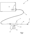
- a coagulation device 10 which includes a coagulation and dissection instrument 11 for laparoscopic surgery and a device 12 serving to feed the same.
- the instrument 11 is connected to the device 12 via a multi-wire cable 13 which conducts electrical current from the device 12 to the instrument 11 for coagulation and/or dissection of biological tissue and which may also contain at least one signal line to transmit commands for release and Blocking the electrical energy from the instrument 11 to the device 12 to conduct.
- the instrument 11 has a housing 14 with a handle 15 and an operating element 16 for actuating a tool 17 which is arranged on the distal end of a shaft 18 extending away from the housing 14 .
- the invention can also be implemented in an instrument for use in open surgery. A shank 18 of such an instrument can then be designed according to the instrument in terms of structure and diameter figure 1 differ and an electrical circuit according to Figures 5 to 10 exhibit.
- the invention can be implemented on an instrument 11 whose tool 17 is controlled by other means, for example by control means of a robot or arms of scissors or pliers acting directly on the axis of articulation of the tool 17. With such an instrument 11, the housing 14, the handle 15 and the operating element 16 can then be partially omitted or designed differently.
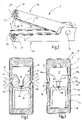
- Tool 17 is in figure 2 illustrated in a little more detail. It is designed in the manner of a pair of pliers and has a first branch 19 and a second branch 20, which are connected to one another at a hinge 21 or other joint in such a way that at least one of the branches 19, 20 rests on the other branch (20 or 19) is movable towards and away from it.
- the opening and closing movement of the branches 19, 20 is controlled by the operating element 16 or two manual branches, for example an open surgical instrument.
- the first branch 19 has at least one first coagulation electrode.
- two first coagulation electrodes 22, 23 are provided, which are provided at the outermost ends of two legs 24, 25 of the first branch 19, which is U-shaped in cross section.
- the first coagulation electrodes 22, 23 are preferably electrically connected to one another. They can also be interrupted along the free ends of each leg 24, 25 by insulating sections 26.
- the second branch 20 is designed accordingly. It also preferably has a U-shaped cross section with two legs 27, 28, at the free ends of which second coagulation electrodes 29, 30 are formed.
- the coagulation electrodes 29, 30 or their coagulation surfaces are at an angle a to an imaginary plane E ( figure 3 ) arranged, which runs in the direction of the longitudinal axis of the branch 20 and rests on both legs 27 and 28.
- the angle a to the plane E is preferably 20 degrees.
- the coagulation surfaces of the coagulation electrodes 29, 30 are preferably arranged sloping towards the bearing surface 39.
- the coagulation electrodes 29, 30 can in turn be interrupted by insulating sections 31 in order to prevent short circuits between the two branches 19, 20 when they are moved towards one another and brought into contact with one another.
- the cutting electrode insert 32 is made of a non-conductive material, preferably plastic, silicone or ceramic. It has a central wall section 34 that thickens towards its base and protrudes from a boundary surface 35a, 35b that extends from the leg 25 to the wall section 34 and from the wall section 34 to the leg 24, respectively.
- the boundary surfaces 35a, 35b lie in a common plane and are perpendicular to the wall section 34 and also perpendicular to the legs 24, 25. The legs 24, 25 protrude beyond the boundary surfaces 35a, 35b.
- the wall section 34 On the surface which points away from the boundary surfaces 35a, 35b and is parallel thereto, the wall section 34 is provided with a cutting electrode 36 which is used for severing biological tissue as required.
- the cutting electrode 36 consisting of a material with good electrical conductivity is embedded in the wall section 34 consisting of insulating material and is only exposed on the side facing the abutment element 33 .
- the abutment element 33 consists, for example, of an elastomer or another electrically insulating, preferably resilient material, for example silicone.
- the branches 19, 20 can, like figure 3 indicates to be provided with insulation 42, 43 on their outer sides in order to prevent electrical contact with the surrounding tissue.
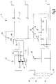
- An electric circuit 44 which can be accommodated in the instrument 11, in particular in the housing 14 of the same, serves to supply the tool 17 with electricity in connection with the device 12.
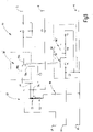
- the electrical circuit 44 is illustrated in FIG. 5 by way of example.
- the circuit 44 has three output terminals M, K and S connected to the electrodes are.
- the connection M serves as a ground connection and is preferably connected to the second branch 20 and correspondingly to the second coagulation electrodes 29, 30.
- the coagulation electrodes 29, 30 thus form the common electrical opposite pole for the cutting electrode 36 and the first coagulation electrodes 22, 23.
- the output connection K is a coagulation connection which is preferably connected to the first branch 19 and thus to the first coagulation electrodes 22, 23.
- the output connection S is the connection for cutting voltage. This connection is connected to the cutting electrode 36 .
- HF output voltage source 47 (schematically indicated in figure 1 ) which is designed as an HF generator and provides electrical energy for operating the instrument 11 .
- a third input connection 48 is used to activate or deactivate the HF output voltage source 47.
- the instrument contains a transformer 49 which can be in the form of an autotransformer. It can have a primary winding 52 divided into two partial windings 50, 51, and a secondary winding 53 which is connected in series with the primary winding 52 according to the autotransformer principle. However, other transformer arrangements with separate primary and secondary windings are also possible.
- the input connection 46 is connected to the primary winding 52 , this connection of the primary winding 52 also representing a coagulation voltage source 54 .
- the upper end of the secondary winding 53 represents a cutting voltage source 55.
- the lower end of the primary winding 52 is connected to ground, ie the input terminal 45 and the output terminal M, directly or, if desired, via a coupling capacitor 56.
- the led out between the partial windings 50, 51 Connection of the transformer 49 can serve as a low voltage source 57.
- the ratio of the number of turns of the first partial winding 50 to the second partial winding 51 to the secondary winding 53 is preferably 11:11:77.
- a supply voltage of, for example, 100 V (HF) (measured against ground, ie input terminal 45) present at the input connection 46 is passed on as a coagulation voltage to the point forming the coagulation voltage source, while the cutting voltage source 55 delivers approximately 450 V measured against ground.
- a conductive path extends from the cutting voltage source 55 to the output terminal S, i.e. to the cutting electrode 36.
- a capacitor preferably several nanofarads
- a resistor severe 10 k2
- Sparking would lead to a direct component of the current at the connection 46, which can be detected by the device. If spark detection is not desired, the resistor R and the capacitor 56 can also be omitted.
- a circuit breaker 58 with a movable contact 58b and at least one fixed contact 58a, 58c.
- the power switch 58 connects the cutting voltage source 55 to the cutting electrode in the non-actuated state. In the actuated state, on the other hand, the power switch 58 connects the cutting electrode 36 to a different voltage, for example to the low-voltage source 57.
- the output connection K for the coagulation voltage is connected to one of the branches, preferably the first branch 19, which also accommodates the cutting electrode insert 32.
- a capacitor C1 can be provided in the corresponding current path. This can serve to limit the coagulation current and preferably has a value of several nF.
- the coagulation current preferably has a frequency between 300 kHz and 400 kHz kHz and is available as CW (continuous wave, ie uninterrupted HF voltage).
- the circuit 44 preferably includes an activation switch 62, which may be a coagulation activation switch 59 or a cutting activation switch 60. Both switches 59, 60 can be actuated by a common actuating element 61, for example by a rocker ( figure 1 ) such that actuation of activation switch 62 closes either cutting activation switch 59 or coagulation activation switch 60, but not both simultaneously. In the center position of the rocker, neither of the two switches 59, 60 is closed.
- the switches 59, 60 can be arranged in parallel with resistors R1, R2 which are connected in series with a third resistor R3.
- the series connection of the resistors R1 to R3 is preferably provided between the input terminals 48,45. To avoid interference, the resistors R1, R2, R3 can be bridged individually or in series by one or more capacitors C2.
- a bridging of one of the two resistors R1 or R2 is detected by the device connected to the connection 48 and interpreted as a command to activate the HF output voltage source 47. This is thus activated both when the coagulation activation switch 59 is actuated and when the cutting activation switch 60 is actuated. If both switches 59, 60 are open, the HF output voltage source 47 is deactivated.
- a special feature lies in the mechanical connection between the coagulation activation switch 59 and the power switch 58. These are connected in such a way that when the actuating element 61 is actuated accordingly, the power switch 58 first opens the connection between the cutting voltage source 55 and the output terminal S or the cutting electrode 36, ie between the contacts 58a and 58b, before the coagulation activation switch 59 closes.
- the circuit breaker 58 preferably works without hysteresis.
- the coagulation activation switch 59 can have a clearly noticeable switching hysteresis in order to give the operator tactile feedback about the activation of the coagulation mode or the cutting mode.
- the hysteresis range of the movement of the switch is dimensioned such that the power switch 58 is switched over outside the hysteresis range of the coagulation activation switch 60 .
- the device 10 described so far works as follows:
- the instrument 11 is connected to the device 12 in operation.
- the operator can then grasp tissue with the instrument 11 and close the branches 19 , 20 by actuating the operating element 16 .
- He can, for example, take a hollow organ, such as a blood vessel, which then how figure 4 shows is taken between the first coagulation electrodes 22, 23 and the second coagulation electrodes 29, 30 and clamped.
- the cutting activation switch 60 is actuated.
- the instrument 11 now receives a supply voltage which is provided as a coagulation voltage at the coagulation voltage source 54 for the coagulation electrodes 22, 23.
- the transformer 49 generates the cutting voltage, which is provided as a cutting voltage source 55 at the transformer output and is conducted to the cutting electrode 36 via the power switch 58 .
- the coagulation activation switch 59 If the operator decides to refrain from dissection and only to carry out coagulation, he actuates on the other hand, the coagulation activation switch 59. In doing so, it first switches over the power switch 58, so that the cutting electrode 36 is connected to the low-voltage source 57. Only then does the coagulation activation switch 59 close and thereby activate the supply voltage source 47. Coagulation voltage from the coagulation voltage source 54 thus reaches the connection K, ie the coagulation electrodes 22, 23, while the cutting electrode 36 receives a lower voltage of, for example, only half the coagulation voltage. This reduces or avoids cutting effects on the cutting electrode 36 .
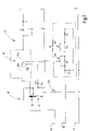
- circuit 44 after figure 6 has a transformer 49 with an undivided primary winding 52 .
- circuit 44 does not include a low voltage source.
- the contact 58a of the power switch 58 is connected to the first end of the secondary winding 53, ie to the cutting voltage source 55, as above, the contact 58c of the power switch 58 is connected to the coagulation voltage source 54.
- actuation of the coagulation activation switch 59 results in disconnection of the cutting current path prior to activation of the HF output voltage source 47. Releasing the coagulation activation switch 59 results in deactivation of the HF output voltage source 47 before the cutting current path is closed again by the switch 58 . Otherwise applies to the Figures 1 to 5 given description based on the reference numerals already introduced accordingly.
- a current-limiting device in the circuit 44 in the path leading from the coagulation voltage source 54 to the contact 58c of the power switch 58.
- This can be, for example, a capacitor C3 or another component, for example a coil (inductance), a resistor or a combination of two or more such components.
- the impedance of the capacitor C3 or another current-limiting component is dimensioned in such a way that the current reaching the cutting electrode 36 in the coagulation mode is limited and thus no longer has a cutting effect. Otherwise applies to the Figures 1 to 5 given description based on the reference numerals already introduced accordingly.
- the contact 58c of the power switch 58 may also be connected to the cutting voltage source 55 via the current-limiting component, for example the capacitor C3.
- the current-limiting component for example the capacitor C3.
- FIG. 9 shows, it is also possible to design the circuit breaker 58 not as a changeover switch, as is the case in all the above embodiments, but as an opener (ie contact 58c is missing).
- the opener is in turn designed to lead the coagulation activation switch 59, ie it opens before the coagulation activation switch 59 closes and it only closes after the coagulation activation switch 59 has opened.
- the Cutting electrode 36 is potential-free in the coagulation mode and therefore has no current. Otherwise applies to the Figures 1 to 5 given description based on the reference numerals already introduced accordingly.
- the power switch 58 is a normally open contact which provides a conductive connection between the contacts 58a, 58b when the cutter activation switch 60 is activated.
- the circuit breaker leads the cutting activation switch 60 when it is closed and lags behind the cutting activation switch 60 when it is deactivated.
- the circuit breaker 58 remains open.
- the cutting electrode can be currentless or carry a negligible current through the parasitic capacitance of the power switch 58 . Otherwise applies to the Figures 1 to 5 given description based on the reference numerals already introduced accordingly.
- the mechanical connection is alternatively between the power switch 58 and the cutting activation switch 60 instead of between the power switch 58 and the coagulation activation switch 59 .
- contact 58b is then connected to contact 58c.
- the power switch 58 switches over in advance in order to establish the connection between the contact 58a and the contact 58b before the cutting activation switch 60 is closed.
- the power switch 58 toggles lagging.
- the coagulation activation switch 59 is actuated, the power switch 58 remains in the idle state and the contact 58b therefore remains connected to the contact 58c.
- connection 46 serving for connection to an HF output voltage source 47
- two connections 46a, 46b are provided on the plug, see FIG figure 10 .
- the connection 46a is connected to a coagulation voltage source provided in the device 12
- the connection 46b is connected to a cutting voltage source provided in the device 12 . Both are activated simultaneously by actuation of one of the switches 59, 60, the power switch 58 being switched in the same switching sequence as the coagulation activation switch 59 as described above and thus suppressing any cutting action in coagulation mode.
- the circuit breaker 58 can also be connected or coupled to the cutting activation switch 60 and the contact 58b can be connected to the contact 58c in the circuit breaker 58 in the idle state (not shown).
- the power switch 58 when the cutting activation switch 60 is actuated, the power switch 58 is switched over in advance so that the cutting action is permitted in the cutting mode.
- the power switch 58 When the cutting activation switch 60 is released, the power switch 58 subsequently returns to the idle state, so that the cutting effect remains suppressed in the event of a subsequent coagulation activation. Otherwise applies to the Figures 1 to 5 given description based on the reference numerals already introduced accordingly.
- the coagulation device 10 contains an instrument 11 whose tool 17 has coagulation electrodes 22 , 23 , 27 , 28 and a cutting electrode 36 .
- the electrodes are powered by a circuit 44 which includes a coagulation power source 54 and a cutting power source 55 or is connectable to such sources.
- the device has a Cutting activation switch 60 and a coagulation activation switch 59 on. The first is connected to a power switch 58 which, in the coagulation mode, disconnects the current path from the cutting voltage source 55 to the cutting electrode 36 before the coagulation voltage source 54 is activated. This provides the user with a simple, reliable means of being able to carry out complicated operations flexibly.
- the coagulation device (10) contains an instrument (11) whose tool (17) has coagulation electrodes (22, 23, 27, 28) and a cutting electrode (36).
- the electrodes are powered by a circuit (44) which includes or is connectable to a coagulation power source (54) and a cutting power source (55).
- the device has a cutting activation switch (60) and a coagulation activation switch (59).
- the first is connected to a power switch 58 which, in cutting mode, connects the current path from the cutting voltage source (55) to the cutting electrode (36) before the cutting voltage source 55 or the HF output voltage source 47 and the coagulation voltage source 54 is activated. This provides the user with a simple, reliable means of being able to carry out complicated operations flexibly.
- Reference sign 10 coagulation device 11 Instrument for coagulation and dissection of biological tissue 12 equipment 13 cable 14 housing 15 handle 16 control element 17 tool 18 shaft 19 first branch of the tool 17 20 second branch of tool 17 21 hinge 22, 23 first coagulation electrodes 24, 25 Legs of the first branch 19 26 insulating sections 27, 28 Leg of the second branch 20 29, 30 second coagulation electrodes 31 insulating sections 32 cutting electrode insert 33 abutment element 34 middle wall section 35a, 35b boundary surface 36 cutting electrode 39 contact surface 42, 43 insulation 44 circuit M, K, S output connections 45, 46 Circuit 44 input terminals 47 HF output voltage source (HF generator) 48 input port 49 transformer 50, 51 partial windings 52 primary winding 53 secondary winding 54 coagulation voltage source 55 cutting voltage source 56 coupling capacitor 57 low voltage source C, C1, C2, C3 capacitors R, R1, R2, R3 resistors 58 circuit breaker 58a Fixed contact of switch 58 (normally closed) 58b moving contact of switch 58 58c Fixed contact of switch 58 (NO contact) 59
Description
Die Erfindung betrifft ein Instrument zur Dissektion und Koagulation oder bedarfsweise nur zur Koagulation von biologischem Gewebe.The invention relates to an instrument for dissection and coagulation or, if necessary, only for coagulation of biological tissue.
Instrumente zur Koagulation und Dissektion von biologischem Gewebe sind beispielsweise aus der
Ein ähnliches Instrument ist aus der
Ein weiteres zur gleichen Gattung gehöriges Instrument ist aus der
Zur elektrischen Steuerung des Koagulations- und Dissektionsprozesses offenbart die
Bei der praktischen Anwendung kann es wünschenswert sein, die Abläufe der Koagulation und Dissektion manuell zu steuern. Dabei kann es vorkommen, dass der Anwender zum Beispiel nur eine Koagulation oder nur eine Dissektion durchführen will oder dass er nach Koagulation und Dissektion nochmals koagulieren will.In practice, it may be desirable to manually control the coagulation and dissection processes. It can happen that the user only wants to carry out a coagulation or a dissection, for example, or that he wants to coagulate again after coagulation and dissection.
Aus der
Es ist Aufgabe der Erfindung, ein Instrument anzugeben, das eine verlässliche manuelle Steuerung des Koagulierens und Schneidens ermöglicht, wobei dazu eine technisch möglichst einfache Lösung angestrebt wird.It is the object of the invention to specify an instrument that enables reliable manual control of the coagulation and cutting, the aim being a technically simple solution.
Diese Aufgabe wird mit dem Instrument nach Anspruch 1 gelöst:This object is solved with the instrument according to claim 1:
Das erfindungsgemäße Instrument kann zur bedarfsweisen Koagulation und Dissektion von biologischem Gewebe eingesetzt werden. Es umfasst ein Werkzeug mit wenigstens zwei Koagulationselektroden, von denen mindestens eine in Bezug auf die andere beweglich ist, so dass sie insgesamt gesehen relativ zueinander beweglich sind. Sie dienen dazu, zwischen einander Gewebe zu fassen und, falls gewünscht, mechanisch zusammen zu drücken. Weiter ist wenigstens eine Schneidelektrode vorgesehen, um zwischen den Koagulationselektroden gefasstes Gewebe bedarfsweise zu durchtrennen. Die Trennung erfolgt dabei wiederum durch elektrische Einwirkung. Sie kann durch mechanische Einwirkung der Schneidelektrode auf das Gewebe unterstützt sein.The instrument according to the invention can be used for coagulation and dissection of biological tissue as required. It comprises a tool with at least two coagulation electrodes, at least one of which is movable with respect to the other so that, viewed as a whole, they are relative to one another are movable. They serve to grasp tissue between one another and, if desired, to mechanically press them together. At least one cutting electrode is also provided in order to cut through tissue held between the coagulation electrodes as required. The separation is again effected by electrical action. It can be supported by the mechanical action of the cutting electrode on the tissue.
In dem Instrument ist eine elektrische Schaltung vorgesehen, die ausgangsseitig an die Koagulationselektroden und an die Schneidelektrode angeschlossen ist. Eingangsseitig ist die elektrische Schaltung an eine Versorgungsspannungsquelle anschließbar. Die Versorgungsspannungsquelle ist vorzugsweise eine HF-Ausgangsspannungsquelle. Die HF-Ausgangsspannungsquelle speist eine Schneidspannungsquelle sowie eine Koagulationsspannungsquelle, die Bestandteil der elektrischen Schaltung sein können. Es ist jedoch auch möglich, die Schneidspannungsquelle und die Koagulationsspannungsquelle extern bereit zu stellen, wobei das Instrument mit seiner elektrischen Schaltung an diese Quellen anschließbar ist. Die Schneidspannungsquelle ist durch einen Ausgang eines Transformators gebildet, der eingangsseitig an die HF-Ausgangsspannungsquelle angeschlossen ist. Der Transformator ist im Instrument angeordnet.An electrical circuit is provided in the instrument, which is connected on the output side to the coagulation electrodes and to the cutting electrode. On the input side, the electrical circuit can be connected to a supply voltage source. The supply voltage source is preferably an HF output voltage source. The HF output voltage source feeds a cutting voltage source and a coagulation voltage source, which can be part of the electrical circuit. However, it is also possible to provide the cutting voltage source and the coagulation voltage source externally, with the instrument being able to be connected to these sources with its electrical circuit. The cutting voltage source is formed by an output of a transformer which is connected to the HF output voltage source on the input side. The transformer is located in the instrument.
Die elektrische Schaltung enthält einen Leistungsschalter zur wahlweisen Trennung oder Zuschaltung der Schneidelektrode von bzw. zu der Schneidspannungsquelle sowie einen Schalter zur wahlweisen Aktivierung der Koagulationsspannungsquelle bzw. der HF-Ausgangsspannungsquelle. Ein in dem Instrument vorhandener Transformator kann als Koagulationsspannungsquelle dienen und zugleich von der Koagulationsspannung gespeist werden, die von der HF-Ausgangsspannungsquelle geliefert werden kann. Die Aktivierung der Koagulationsspannungsquelle kann direkt erfolgen, indem die Koagulationsspannungsquelle (z.B. der Transformator) als solche aktiviert (ein- und ausgeschaltet) wird. Bevorzugt erfolgt die Aktivierung indirekt, indem der Koagulationsaktivierungsschalter zur Aktivierung (und Deaktivierung) der HF-Ausgangsspannungsquelle dient, die beispielsweise durch einen HF-Generator eines speisenden medizinischen Geräts gebildet ist, an das das Instrument angeschlossen ist. Erhält das Instrument von der HF-Ausgangsspannungsquelle Versorgungsspannung, ist die Koagulationsspannungsquelle aktiv.The electrical circuit contains a power switch for selectively disconnecting or connecting the cutting electrode to or from the cutting voltage source and a switch for selectively activating the coagulation voltage source or the HF output voltage source. A transformer present in the instrument can serve as a coagulation voltage source and at the same time be fed by the coagulation voltage that can be supplied by the HF output voltage source. The activation of the coagulation voltage source can take place directly by activating (switching on and off) the coagulation voltage source (eg the transformer) as such. Preferred activation occurs indirectly, in that the coagulation activation switch serves to activate (and deactivate) the HF output voltage source, which is formed, for example, by an HF generator of a feeding medical device to which the instrument is connected. If the instrument receives supply voltage from the HF output voltage source, the coagulation voltage source is active.
Bei dem erfindungsgemäßen Instrument sind der Leistungsschalter und der Steuerschalter zur Aktivierung der Koagulationsspannungsquelle von einem gemeinsamen Betätigungselement seriell gesteuert. Der Steuerschalter kann ein Koagulationsaktivierungsschalter oder ein Schneidaktivierungsschalter sein. Die serielle Steuerung des Steuerschalters und des Leistungsschalters bedeutet, dass eine manuelle Betätigung des Betätigungselements zunächst dazu führt, dass einer der Schalter, vorzugsweise der Leistungsschalter, betätigt, d.h. geöffnet oder geschlossen wird, und dass der Schalter zur Aktivierung der Koagulationsspannungsquelle erst danach, d.h. dann geschlossen wird, wenn der Leistungsschalter den zur Schneidelektrode führenden Strompfad bereits unterbrochen oder eben bereits geschlossen hat. Auf diese Weise ist beim Koagulieren die Schneidelektrode von der Schneidspannungsquelle getrennt, bevor eine Aktivierung, zum Beispiel der HF-Ausgangsspannungsquelle, erfolgt. Bei der alternativen Ausführungsform mit als Schließer ausgebildetem Leistungsschalter ist die Schneidelektrode mit der Schneidspannungsquelle verbunden, bevor eine Aktivierung erfolgt. Somit können die Koagulationsspannungsquelle und die Schneidspannungsquelle gleichzeitig aktiviert werden, ohne dass im Koagulationsmodus die Schneidelektrode Schneidspannung erhalten würde.In the instrument according to the invention, the power switch and the control switch for activating the coagulation voltage source are controlled in series by a common actuating element. The control switch can be a coagulation activation switch or a cutting activation switch. The serial control of the control switch and the circuit breaker means that manual actuation of the actuating element first results in one of the switches, preferably the circuit breaker, being actuated, i.e. opened or closed, and the switch for activating the coagulation voltage source only afterwards, i.e. then is closed when the circuit breaker has already interrupted the current path leading to the cutting electrode or has already closed it. In this way, during coagulation, the cutting electrode is separated from the cutting voltage source before activation, for example of the HF output voltage source, takes place. In the alternative embodiment with a circuit breaker designed as a make contact, the cutting electrode is connected to the cutting voltage source before activation takes place. Thus, the coagulation voltage source and the cutting voltage source can be activated simultaneously without the cutting electrode receiving cutting voltage in the coagulation mode.
Mit diesem Konzept lässt sich mit einer besonders einfachen Schaltung ein sehr verlässlich arbeitendes feinfühlig zu steuerndes Instrument erstellen, das an einen HF-Generator mit zweipoligem Ausgang anschließbar und wahlweise sowohl zum Koagulieren als auch zum Schneiden verwendbar ist, wobei das Umschalten mit einfachsten Mitteln direkt am Instrument manuell erfolgen kann.With this concept, a very reliably working, sensitively controlled instrument can be created with a particularly simple circuit, which can be connected to an HF generator with a two-pole output and optionally for coagulation as well as for cutting, whereby switching can be done manually directly on the instrument with the simplest of means.
Bei dem erfindungsgemäßen Instrument sind der Leistungsschalter und der Koagulationsaktivierungsschalter derart mit dem Betätigungselement verbunden, dass bei einer Betätigung des Betätigungselements zunächst der Leistungsschalter öffnet, bevor der Koagulationsaktivierungsschalter schließt, und dass bei einer Freigabe des Betätigungselements der Koagulationsaktivierungsschalter öffnet, bevor der Leistungsschalter schließt. Dies stellt sicher, dass im reinen Koagulationsmodus stets die Schneidelektrode von der Schneidspannungsquelle getrennt ist, und zwar unabhängig davon, ob diese tatsächlich aktiv ist oder nicht. Mit dem genannten Konzept wird die Möglichkeit eröffnet, die Schneidspannungsquelle an einem Schaltungspunkt auszubilden bzw. bereitzustellen, der transformatorisch fest an die Koagulationsspannung gekoppelt ist, wobei die Koagulationsspannung von der HF-Ausgangsspannungsquelle geliefert wird. Dies führt zu einem einfachen Aufbau des Instruments.In the instrument according to the invention, the power switch and the coagulation activation switch are connected to the actuating element in such a way that when the actuating element is actuated, the power switch first opens before the coagulation activation switch closes, and when the actuating element is released, the coagulation activation switch opens before the power switch closes. This ensures that in pure coagulation mode the cutting electrode is always disconnected from the cutting voltage source, regardless of whether it is actually active or not. The concept mentioned opens up the possibility of designing or providing the cutting voltage source at a circuit point which is transformer-connected to the coagulation voltage, with the coagulation voltage being supplied by the HF output voltage source. This leads to a simple construction of the instrument.
Der Leistungsschalter, der den Schneidstrom führt, d.h. die Schneidspannungsquelle mit der Schneidelektrode verbindet, ist vorzugsweise ein Ruhekontakt. Das heißt er stellt in nicht betätigtem Zustand (Ruhezustand) eine elektrische Verbindung zwischen der Schneidspannungsquelle und der Schneidelektrode her. In betätigtem Zustand trennt er hingegen die Schneidelektrode von der Schneidspannungsquelle. In betätigtem Zustand nimmt er den Koagulationsmode ein. In diesem kann er die Schneidelektrode mit der Koagulationsspanungsquelle verbinden. In diesem Fall kann die Schneidelektrode zur Koagulationswirkung beitragen. Es kann jedoch auch gewünscht sein, die Schneidelektrode im Koagulationsmodus mit einer Spannung zu beaufschlagen, die niedriger ist als die Koagulationsspannung, um dadurch jede Schneidwirkung auszuschließen. Damit kann der Leistungsschalter in betätigtem Zustand die Schneidelektrode mit einer Minderspannungsquelle verbinden, die eine verminderte Spannung bereitstellt. Diese mindere Spannung kann z.B. einen Bruchteil der Koagulationsspannung betragen, bspw. 75% oder 50% derselben. Die Minderspannungsquelle kann ein primärseitig von der Koagulationsspannung gespeister Transformator sein. Der Transformator kann als Spartransformator ausgebildet sein, so dass die Minderspannungsquelle von einer Anzapfung einer Wicklung gebildet wird, die mit der Koagulationsspannung beaufschlagt ist.The circuit breaker that carries the cutting current, ie connects the cutting voltage source to the cutting electrode, is preferably a normally closed contact. This means that when it is not actuated (idle state), it creates an electrical connection between the cutting voltage source and the cutting electrode. In the actuated state, on the other hand, it separates the cutting electrode from the cutting voltage source. When actuated, it assumes the coagulation mode. In this he can connect the cutting electrode to the coagulation voltage source. In this case, the cutting electrode can contribute to the coagulation effect. However, it may also be desirable to apply a voltage to the cutting electrode in the coagulation mode which is lower than the coagulation voltage, in order to thereby preclude any cutting action. So that the circuit breaker can be actuated Connect the cutting electrode to a reduced voltage source that provides a reduced voltage. This reduced tension can be, for example, a fraction of the coagulation tension, for example 75% or 50% of the same. The low-voltage source can be a transformer fed by the coagulation voltage on the primary side. The transformer can be designed as an autotransformer, so that the low-voltage source is formed by a tap on a winding to which the coagulation voltage is applied.
Es ist auch möglich, dass der Leistungsschalter die Schneidelektrode im aktivierten Zustand des Koagulationsaktivierungsschalters über ein Strombegrenzungsmittel mit der Schneidspannungsquelle oder mit der Koagulationsspannungsquelle verbindet. Das Strombegrenzungsmittel kann ein Kondensator, ein ohmscher Widerstand, ein nichtlinearer Widerstand, ein induktives Bauelement oder eine Kombination aus zwei oder mehreren der genannten Bauelemente sein. Jedenfalls ist es so bemessen, dass es den zur Schneidelektrode geleiteten Strom in dem Koagulationsmodus auf einen Wert begrenzt, der nicht zum Schneiden von Gewebe führt.It is also possible for the power switch to connect the cutting electrode to the cutting voltage source or to the coagulation voltage source via a current limiting means when the coagulation activation switch is in the activated state. The current limiting means can be a capacitor, an ohmic resistor, a non-linear resistor, an inductive component or a combination of two or more of the components mentioned. In any event, it is dimensioned to limit the current delivered to the cutting electrode in the coagulation mode to a value that does not result in cutting of tissue.
Alternativ ist es auch möglich, die Schneidelektrode im Koagulationsmodus potentialfrei zu schalten, d.h. mit keiner elektrischen Quelle zu verbinden. In diesem Fall nimmt die Schneidelektrode am Koagulationsprozess nicht teil, so dass im Bereich der Schneidelektrode eine geringe oder keine Gewebeschrumpfung eintritt.Alternatively, it is also possible to switch the cutting electrode potential-free in coagulation mode, i.e. not to connect it to any electrical source. In this case, the cutting electrode does not take part in the coagulation process, so that little or no tissue shrinkage occurs in the area of the cutting electrode.
Generell ist es vorteilhaft, wenn die Schneidelektrode und ein eventuell vorhandenes Widerlager in Bezug aufeinander federnd nachgiebig ausgebildet sind. Beispielsweise kann die Schneidelektrode federnd gelagert sein, um in Schlussrichtung der Branche beweglich zu sein. Zusätzlich oder alternativ kann das Widerlager beweglich angeordnet oder elastisch ausgebildet sein, um gleichfalls in Bewegungsrichtung der Branche bei schließendem Werkzeug der Schneidelektrode ausweichen zu können. Dies kann bei allen vorstehend erläuterten Ausführungsformen der elektrischen Schaltung Anwendung finden. Besonders vorteilhaft ist dies jedoch bei potentialfrei geschalteter Schneidelektrode. Hier ist es möglich im Koagulationsmodus ohne jegliche Schneidwirkung einen wenig geschrumpften Gewebestreifen zwischen zwei Versiegelungssäumen zu erzeugen, die ihrerseits von den Koagulationselektroden erzeugt wurden.It is generally advantageous if the cutting electrode and any abutment that may be present are designed to be resiliently flexible in relation to one another. For example, the cutting electrode can be resiliently mounted in order to be movable in the closing direction of the branch. Additionally or alternatively the abutment can be movably arranged or designed to be elastic in order to be able to dodge the cutting electrode in the direction of movement of the branch when the tool is closing. This can be used in all of the embodiments of the electrical circuit explained above. However, this is particularly advantageous when the cutting electrode is switched to be potential-free. Here it is possible in the coagulation mode without any cutting effect to create a slightly shrunken tissue strip between two sealing seams, which in turn were created by the coagulation electrodes.
Das Koagulationsinstrument kann einen Schneidaktivierungsschalter enthalten, der dazu dient, die Schneidspannungsquelle direkt oder indirekt zu aktivieren. Zur indirekten Aktivierung ist er beispielsweise steuernd mit einer HF-Ausgangsspannungsquelle eines Generators verbunden, der eine geeignete HF-Ausgangsspannung zum Betrieb des Instruments abgibt. Diese HF-Ausgangsspannung kann eine Schneidspannung oder eine Koagulationsspannung sein. Ein in dem Instrument vorhandener Transformator kann als Schneidspannungsquelle dienen und von der Koagulationsspannung gespeist werden. Alternativ kann der Transformator auch von der Schneidspannung gespeist werden und die Koagulationsspannung liefern. Wird der Steuerschalter zur Aktivierung des Schneidmodus betätigt, ist der im Ruhezustand befindliche Leistungsschalter geschlossen und verbindet somit die Schneidspannungsquelle mit der Schneidelektrode.The coagulation instrument may include a cutting activation switch operable to directly or indirectly activate the cutting voltage source. For indirect activation, it is connected, for example, in a controlling manner to an HF output voltage source of a generator, which emits a suitable HF output voltage for operating the instrument. This HF output voltage can be a cutting voltage or a coagulation voltage. A transformer present in the instrument can serve as a cutting voltage source and be fed by the coagulation voltage. Alternatively, the transformer can also be fed from the cutting voltage and supply the coagulation voltage. If the control switch is actuated to activate the cutting mode, the power switch, which is in the idle state, is closed and thus connects the cutting voltage source to the cutting electrode.
Vorzugsweise sind der Schneidaktivierungsschalter und der Koagulationsaktivierungsschalter gegeneinander verriegelt, so dass sie lediglich alternativ betätigt werden können. Beispielsweise können die beiden Schalter ein gemeinsames Betätigungselement zum Beispiel in Gestalt einer Schaltwippe aufweisen. Diese stellt sicher, dass nur entweder der Schneidaktivierungsschalter oder der Koagulationsaktivierungsschalter betätigt wird.Preferably, the cutting activation switch and the coagulation activation switch are interlocked so that they can only be operated alternatively. For example, the two switches can have a common actuating element, for example in the form of a rocker switch. This ensures that only either the cutting activation switch or the coagulation activation switch is actuated.
Weitere Einzelheiten vorteilhafter Ausführungsformen der Erfindung sind Gegenstand der Zeichnung, der Beschreibung oder von Ansprüchen. Es zeigen:
-
Figur 1 eine Koagulations- und Dissektionseinrichtung bestehend aus einem Koagulations- und Dissektionsinstrument und einem speisenden Gerät, an das das Instrument mittels eines Kabels angeschlossen ist, in schematischer Darstellung, -
Figur 2 das Werkzeug des Instruments nachFigur 1 , in perspektivischer teilweiser geschnittener Darstellung, -
Figur 3 und 4 das Instrument nachFigur 2 mit und ohne biologisches Gewebe, in Querschnittsdarstellung, -
Figur 5 verschiedene Ausführungsformen der elektrischen Schaltung zur Speisung der Elektroden des Instruments.bis 10
-
figure 1 a coagulation and dissection device consisting of a coagulation and dissection instrument and a feeding device to which the instrument is connected by a cable, in a schematic representation, -
figure 2 the tool of the instrumentfigure 1 , in a perspective partially sectioned view, -
Figure 3 and 4 the instrument afterfigure 2 with and without biological tissue, in cross-section, -
Figure 5 to 10 various embodiments of the electric circuit for feeding the electrodes of the instrument.
In
Das Instrument 11 weist ein Gehäuse 14 mit Handgriff 15 und Bedienelement 16 zur Betätigung eines Werkzeugs 17 auf, das an dem distalen Ende eines sich von dem Gehäuse 14 weg erstreckenden Schafts 18 angeordnet ist. Die Erfindung kann auch an einem Instrument zur offenchirurgischen Anwendung verwirklicht sein. Ein Schaft 18 eines solchen Instruments kann dann im Aufbau und Durchmesser vom Instrument gemäß
Das Werkzeug 17 ist in
Die erste Branche 19 weist mindestens eine erste Koagulationselektrode auf. Im Ausführungsbeispiel sind zwei erste Koagulationselektroden 22, 23 vorgesehen, die an den äußersten Enden zweier Schenkel 24, 25 der im Querschnitt u-förmig ausgebildeten ersten Branche 19 vorgesehen sind. Die ersten Koagulationselektroden 22, 23 sind vorzugsweise elektrisch untereinander verbunden. Außerdem können sie längs der freien Enden jedes Schenkels 24, 25 durch isolierende Abschnitte 26 unterbrochen sein.The
Die zweite Branche 20 ist entsprechend ausgebildet. Sie weist ebenfalls vorzugsweise einen U-förmigen Querschnitt mit zwei Schenkeln 27, 28 auf, an deren freien Enden zweite Koagulationselektroden 29, 30 ausgebildet sind. Die Koagulationselektroden 29, 30 beziehungsweise deren Koagulationsflächen sind in einem Winkel a zu einer gedachten Ebene E (
Während eine Branche, beispielsweise die erste Branche 19, in einer mittleren Nut einen Schneidelektrodeneinsatz 32 aufnimmt, ist gegenüber liegend in einer entsprechenden Nut der zweiten Branche 20 ein Widerlagerelement 33 angeordnet (
An der von den Begrenzungsflächen 35a, 35b weg weisenden und dazu parallelen Fläche ist der Wandabschnitt 34 mit einer Schneidelektrode 36 versehen, die zur bedarfsweisen Durchtrennung von biologischem Gewebe dient. Die aus einem elektrisch gut leitfähigen Material bestehende Schneidelektrode 36 ist in den aus isolierendem Material bestehenden Wandabschnitt 34 eingebettet und liegt nur an der dem Widerlagerelement 33 zugewandten Seite frei. In geschlossenem Zustand des Werkzeugs 17 findet die Schneidelektrode 36 Anlage an dem Widerlagerelement 33, das eine sich von einem Schenkel 28 zu dem anderen Schenkel 27 erstreckende Gewebeauflagefläche 39 aufweist. Das Widerlagerelement 33 besteht z.B. aus einem Elastomer oder einem sonstigen elektrisch isolierenden vorzugsweise federnd nachgiebigem Material, z.B. Silikon.On the surface which points away from the
Die Branchen 19, 20 können, wie
Zur elektrischen Versorgung des Werkzeugs 17 dient in Verbindung mit dem Gerät 12 eine elektrische Schaltung 44, die in dem Instrument 11, insbesondere in dem Gehäuse 14 desselben untergebracht sein kann. Die elektrische Schaltung 44 ist in Figur 5 beispielhaft veranschaulicht. Die Schaltung 44 weist drei Ausgangsanschlüsse M, K und S auf, die mit den Elektroden verbunden sind. Im Einzelnen dient der Anschluss M als Masseanschluss und ist vorzugsweise mit der zweiten Branche 20 und entsprechend mit den zweiten Koagulationselektroden 29, 30 verbunden. Damit bilden die Koagulationselektroden 29, 30 den gemeinsamen elektrischen Gegenpol für die Schneidelektrode 36 und die ersten Koagulationselektroden 22, 23. Der Ausgangsanschluss K ist ein Koagulationsanschluss der vorzugsweise mit der ersten Branche 19 und somit mit den ersten Koagulationselektroden 22, 23 verbunden ist. Der Ausgangsanschluss S ist der Anschluss für Schneidspannung. Dieser Anschluss ist mit der Schneidelektrode 36 verbunden.An
Eingangsseitig führen Leitungen durch das Kabel 13 zu dem mit dem Gerät 12 verbundenen Stecker, der mindestens drei Anschlüsse aufweist. Zwei Anschlüsse 45, 46 dienen zum Anschluss an eine HF-Ausgangsspannungsquelle 47 (schematisch angedeutet in
Der Eingangsanschluss 46 ist mit der Primärwicklung 52 verbunden, wobei dieser Anschluss der Primärwicklung 52 zugleich eine Koagulationsspannungsquelle 54 darstellt. Das obere Ende der Sekundärwicklung 53 stellt hingegen eine Schneidspannungsquelle 55 dar. Das untere Ende der Primärwicklung 52 ist direkt oder, falls gewünscht, über einen Koppelkondensator 56 mit Masse, d.h. dem Eingangsanschluss 45 bzw. dem Ausgangsanschluss M verbunden. Der zwischen den Teilwicklungen 50, 51 herausgeführte Anschluss des Transformators 49 kann als Minderspannungsquelle 57 dienen. Vorzugsweise verhalten sich die Windungszahlen der ersten Teilwicklung 50 zur zweiten Teilwicklung 51 zur Sekundärwicklung 53 wie 11:11:77. Damit wird eine an dem Eingangsanschluss 46 anliegende Versorgungsspannung von zum Beispiel 100 V (HF) (gemessen gegen Masse, d.h. Eingangsanschluss 45) als Koagulationsspannung an den die Koagulationsspannungsquelle bildenden Punkt weitergegeben während die Schneidspannungsquelle 55 etwa 450V gemessen gegen Masse liefert.The
Von der Schneidspannungsquelle 55 verläuft ein Leitungspfad zum Ausgangsanschluss S, d.h. zu der Schneidelektrode 36. In diesem Strompfad können ein Kondensator (vorzugsweise mehrere Nanofarad) und ein Widerstand (mehrere 10 k2) vorgesehen sein, um eine Funkenbildungserkennung zu ermöglichen. Eine Funkenbildung würde zu einem Gleichanteil des Stroms an dem Anschluss 46 führen, was geräteseitig erfassbar ist. Ist eine Funkenerkennung nicht gewünscht, können der Widerstand R, sowie der Kondensator 56 auch entfallen. Des Weiteren liegt in dem Strompfad zwischen der Schneidspannungsquelle 55 und der Schneidelektrode ein Leistungsschalter 58 mit einem beweglichen Kontakt 58b und mindestens einem festen Kontakt 58a, 58c. Der Leistungsschalter 58 verbindet in der vorliegenden ersten Ausführungsform in nichtbetätigtem Zustand die Schneidspannungsquelle 55 mit der Schneidelektrode. In betätigtem Zustand verbindet der Leistungsschalter 58 hingegen die Schneidelektrode 36 mit einer anderen Spannung, beispielsweise mit der Minderspannungsquelle 57.A conductive path extends from the cutting
Der Ausgangsanschluss K für die Koagulationsspannung ist mit einer der Branchen, vorzugsweise der ersten Branche 19 verbunden, die auch den Schneidelektrodeneinsatz 32 beherbergt. In dem entsprechenden Strompfad kann ein Kondensator Cl vorgesehen sein. Dieser kann zur Begrenzung des Koagulationsstroms dienen und hat vorzugsweise einen Wert von mehreren nF. Der Koagulationsstrom hat vorzugsweise eine Frequenz zwischen 300 kHz und 400 kHz und liegt als CW (Dauerstrich, d.h. ununterbrochene HF-Spannung) an.The output connection K for the coagulation voltage is connected to one of the branches, preferably the
Die Schaltung 44 enthält vorzugsweise einen Aktivierungsschalter 62, der ein Koagulationsaktivierungsschalter 59 oder ein Schneidaktivierungsschalter 60 sein kann. Beide Schalter 59, 60 können von einem gemeinsamen Betätigungselement 61 aus betätigt werden, beispielsweise durch eine Wippe (
Eine Überbrückung eines der beiden Widerstände R1 oder R2 wird von dem an den Anschluss 48 angeschlossenen Gerät erfasst und als Befehl zur Aktivierung der HF-Ausgangsspannungsquelle 47 interpretiert. Diese wird somit sowohl bei der Betätigung des Koagulationsaktivierungsschalters 59 wie auch bei der Betätigung des Schneidaktivierungsschalters 60 aktiviert. Sind beide Schalter 59, 60 offen ist die HF-Ausgangsspannungsquelle 47 deaktiviert.A bridging of one of the two resistors R1 or R2 is detected by the device connected to the
Eine Besonderheit liegt in der mechanischen Verbindung zwischen dem Koagulationsaktivierungsschalter 59 und dem Leistungsschalter 58. Diese sind so verbunden, dass bei einer entsprechenden Betätigung des Betätigungselements 61 zunächst der Leistungsschalter 58 die Verbindung zwischen der Schneidspannungsquelle 55 und dem Ausgangsanschluss S bzw. der Schneidelektrode 36, d.h. zwischen den Kontakten 58a und 58b, auftrennt, bevor der Koagulationsaktivierungsschalter 59 schließt. Der Leistungsschalter 58 arbeitet dabei vorzugsweise hysteresefrei. Der Koagulationsaktivierungsschalter 59 kann hingegen eine deutlich spürbare Schalthysterese aufweisen, um den Bediener eine taktile Rückmeldung über die Aktivierung des Koagulationsmodus oder des Schneidmodus zu geben. Der Hysteresebereich der Bewegung des Schalters ist dabei so bemessen, dass die Umschaltung des Leistungsschalters 58 außerhalb des Hysterebereichs des Koagulationsaktivierungsschalters 60 erfolgt.A special feature lies in the mechanical connection between the
Die insoweit beschriebene Einrichtung 10 arbeitet wie folgt:
Im Betrieb ist das Instrument 11 an das Gerät 12 angeschlossen. Der Bediener kann dann mit dem Instrument 11 Gewebe erfassen und durch Betätigung des Bedienelements 16 die Branchen 19, 20 schließen. Er kann beispielsweise ein Hohlorgan, z.B. ein Blutgefäß fassen, das dann, wie
The
Entschließt sich der Bediener von einer Dissektion abzusehen und lediglich eine Koagulation durchzuführen, betätigt er hingegen den Koagulationsaktivierungsschalter 59. Dabei schaltet er zunächst den Leistungsschalter 58 um, so dass die Schneidelektrode 36 mit der Minderspannungsquelle 57 verbunden wird. Erst danach schließt der Koagulationsaktivierungsschalter 59 und aktiviert dadurch die Versorgungsspanungsquelle 47. Somit gelangt Koagulationsspannung aus der Koagulationsspannungsquelle 54 an den Anschluss K, d.h. die Koagulationselektroden 22, 23, während die Schneidelektrode 36 eine mindere Spannung von zum Beispiel lediglich der halben Koagulationsspannung erhält. Damit werden Schneideffekte an der Schneidelektrode 36 vermindert oder vermieden.If the operator decides to refrain from dissection and only to carry out coagulation, he actuates on the other hand, the
Bei der vorgestellten Schaltung 44 sind zahlreiche Abwandlungen möglich, die nachfolgend unter Beschränkung auf die Unterschiede zur Schaltung 44 gemäß
Die Schaltung 44 nach
Gemäß
Alternativ kann, wie die Schaltung 44 nach
Wie
Eine weitere mögliche bevorzugte Abwandlung der erfindungsgemäßen Schaltung ist aus
Bei allen Ausführungsformen der
Während bei allen vorstehend beschriebenen Ausführungsformen der Schaltung 44 die Koagulationsspannungsquelle 54 und die Schneidspannungsquelle 55 Teil der Schaltung 44 waren, ist es auch möglich, die beiden Spannungsquellen in dem Gerät 12 vorzusehen. Anstelle eines zur Verbindung mit einer HF-Ausgangsspannungsquelle 47 dienenden Anschluss 46 sind an dem Stecker zwei Anschlüsse 46a, 46b vorgesehen, siehe
Die erfindungsgemäße Koagulationseinrichtung 10 enthält ein Instrument 11, dessen Werkzeug 17 Koagulationselektroden 22, 23, 27, 28 sowie eine Schneidelektrode 36 aufweist. Die Elektroden werden von einer Schaltung 44 gespeist, die eine Koagulationsspannungsquelle 54 und eine Schneidspannungsquelle 55 enthält oder an solche Quellen anschließbar ist. Das Gerät weist einen Schneidaktivierungsschalter 60 und einen Koagulationsaktivierungsschalter 59 auf. Erster ist mit einem Leistungsschalter 58 verbunden, der im Koagulationsmodus den Strompfad von der Schneidspannungsquelle 55 zu der Schneidelektrode 36 trennt, bevor die Koagulationsspannungsquelle 54 aktiviert wird. Damit ist dem Anwender auf einfache Weise ein verlässliches Mittel an die Hand gegeben, um komplizierte Operationen flexibel durchführen zu können.The
Die erfindungsgemäße Koagulationseinrichtung (10) enthält ein Instrument (11), dessen Werkzeug (17) Koagulationselektroden (22, 23, 27, 28) sowie eine Schneidelektrode (36) aufweist. Die Elektroden werden von einer Schaltung (44) gespeist, die eine Koagulationsspannungsquelle (54) und eine Schneidspannungsquelle (55) enthält oder an solche Quellen anschließbar ist. Das Gerät weist einen Schneidaktivierungsschalter (60) und einen Koagulationsaktivierungsschalter (59) auf. Erster ist mit einem Leistungsschalter 58 verbunden, der im Schneidemodus den Strompfad von der Schneidspannungsquelle (55) zu der Schneidelektrode (36) verbindet, bevor die Schneidspannungsquelle 55 bzw. die HF-Ausgangsspannungsquelle 47 und die Koagulationsspannungsquelle 54 aktiviert wird. Damit ist dem Anwender auf einfache Weise ein verlässliches Mittel an die Hand gegeben, um komplizierte Operationen flexibel durchführen zu können.
Claims (12)
- Instrument for coagulation and targeted dissection of biological tissue,with a tool (17) which has at least one first coagulation electrode (22) and one second coagulation electrode (29) that are movable relative to one another in order to hold tissue between them, and which has at least one cutting electrode (36) for cutting through tissue held between the least one first coagulation electrode (22) and the at least one second coagulation electrode (29),with an electrical circuit (44) which is connected to the coagulation electrodes (22, 29) and to the cutting electrode (36) and contains or can be connected to a cutting voltage source (55) and a coagulation voltage source (54), wherein the cutting voltage source (55) is formed by a transformer (49) which is arranged in the instrument (11) and is or can be connected on the input side to the HF output voltage source (47), and wherein the HF output voltage source (47) serves to supply the coagulation voltage source (54),wherein the circuit (44) has three output ports (M, K and S), of which the one output port (M) is a ground port connected to the at least one second coagulation electrode (29), the one further output port (K) is a coagulation port connected to the at least one first coagulation electrode (22), and the other further output port (S) is a port connected to the at least one cutting electrode (36) for a cutting voltage of the cutting voltage source (55),wherein the electrical circuit (44) has a power switch (58) which is arranged in a current path between the cutting voltage source (55) and the cutting electrode (36) and is configured for optional isolation of the cutting electrode (36) from the cutting voltage source (55) or for optional connection of the cutting electrode (36) to the cutting voltage source (55), and an activation switch (62) which is configured for optional activation of the coagulation voltage source (54), the cutting voltage source (55) or the HF output voltage source (47),wherein the activation switch (62) and the power switch (58) are controlled in series by a common actuation element (61).
- Instrument according to claim 1, characterised in that on the input side, the electrical circuit (44) has three ports (45, 46, 48), wherein two ports (45, 46) are configured for connection to the HF output voltage source (47) in order to provide electrical energy for operation of the instrument (11), and wherein a third port (48) is configured for activation or deactivation of the HF output voltage source (47).
- Instrument according to claim 1 or 2, characterised in that the power switch (58) and the activation switch (62) are connected to the actuation element (61) such that when the actuation element (61) is actuated, the power switch (58) closes before the activation switch (62) closes, and that when the actuation element (61) is de-actuated, the activation switch (62) opens before the power switch (58) opens.
- Instrument according to any of the preceding claims, characterised in that the power switch (58) in rest state does not establish an electrical connection between the cutting voltage source (55) and the cutting electrode (36), and in actuated state connects the cutting electrode (36) to the cutting voltage source (55).
- Instrument according to claim 4, characterised in that in rest state, the power switch (58) connects the cutting electrode (36) to the coagulation voltage source (54) or to a reduced voltage source (57) or is switched potential-free.
- Instrument going to claim 5, characterised in that the reduced voltage source (57) is a transformer (49) which is connected to the coagulation voltage source (54) on the primary side.
- Instrument according to claim 4, characterised in that in rest state, the power switch (58) connects the cutting electrode (36) to a current-limiting means (C3).
- Instrument according to any of the preceding claims, characterised in that the instrument (11) has a coagulation activation switch (59) which is configured for activating the HF output voltage source (47).
- Instrument according to any of the preceding claims, characterised in that the instrument (11) has a cutting activation switch (60) which is configured to activate the HF output voltage source (47).
- Instrument according to claim 8 or 9, characterised in that the cutting activation switch (60) and the coagulation activation switch (59) are configured so as to be activatable exclusively alternatively.
- Instrument according to any of the preceding claims, characterised in that the transformer (49) is or can be connected to the coagulation voltage source (54).
- Instrument according to any of the preceding claims, characterised in that the coagulation voltage source (54) is arranged outside the instrument (11).
Priority Applications (8)
| Application Number | Priority Date | Filing Date | Title |
|---|---|---|---|
| EP15182008.1A EP3132765B1 (en) | 2015-08-21 | 2015-08-21 | Coagulation and dissection instrument with improved control |
| PL15182008T PL3132765T3 (en) | 2015-08-21 | 2015-08-21 | Coagulation and dissection instrument with improved control |
| BR102016018296-4A BR102016018296B1 (en) | 2015-08-21 | 2016-08-09 | Instrument for coagulation and, if necessary, for dissection of biological tissue |
| JP2016159715A JP6836859B2 (en) | 2015-08-21 | 2016-08-16 | Coagulation and incision device with improved control |
| CN201610697052.8A CN106562821B (en) | 2015-08-21 | 2016-08-19 | Coagulation and dissection instrument with improved control |
| US15/241,892 US10987157B2 (en) | 2015-08-21 | 2016-08-19 | Coagulation and dissecting instrument with improved control |
| KR1020160105535A KR102573937B1 (en) | 2015-08-21 | 2016-08-19 | Coagulation and dissecting instrument with improved control |
| RU2016134133A RU2696244C2 (en) | 2015-08-21 | 2016-08-19 | Coagulation and cutting tool with improved control |
Applications Claiming Priority (1)
| Application Number | Priority Date | Filing Date | Title |
|---|---|---|---|
| EP15182008.1A EP3132765B1 (en) | 2015-08-21 | 2015-08-21 | Coagulation and dissection instrument with improved control |
Publications (2)
| Publication Number | Publication Date |
|---|---|
| EP3132765A1 EP3132765A1 (en) | 2017-02-22 |
| EP3132765B1 true EP3132765B1 (en) | 2022-03-30 |
Family
ID=53969239
Family Applications (1)
| Application Number | Title | Priority Date | Filing Date |
|---|---|---|---|
| EP15182008.1A Active EP3132765B1 (en) | 2015-08-21 | 2015-08-21 | Coagulation and dissection instrument with improved control |
Country Status (8)
| Country | Link |
|---|---|
| US (1) | US10987157B2 (en) |
| EP (1) | EP3132765B1 (en) |
| JP (1) | JP6836859B2 (en) |
| KR (1) | KR102573937B1 (en) |
| CN (1) | CN106562821B (en) |
| BR (1) | BR102016018296B1 (en) |
| PL (1) | PL3132765T3 (en) |
| RU (1) | RU2696244C2 (en) |
Families Citing this family (6)
| Publication number | Priority date | Publication date | Assignee | Title |
|---|---|---|---|---|
| US11826091B2 (en) * | 2016-08-16 | 2023-11-28 | Xcellanxe Medical Technologies Pvt Ltd | Bipolar electrosurgical cutting and coagulation instrument |
| GB2567480A (en) * | 2017-10-13 | 2019-04-17 | Creo Medical Ltd | Electrosurgical resector tool |
| PL3639779T3 (en) | 2018-10-16 | 2022-11-21 | Erbe Elektromedizin Gmbh | Instrument for coagulation and dissection of biological tissue |
| PL3777739T3 (en) | 2019-08-14 | 2022-06-20 | Erbe Elektromedizin Gmbh | Cutting electrode, surgical instrument and method of manufacturing the cutting electrode |
| EP3895642B1 (en) * | 2020-04-14 | 2023-09-27 | Erbe Elektromedizin GmbH | Device for coagulation and/or dissection of biological tissue and a method of operating a device. |
| EP4026507A1 (en) * | 2021-01-12 | 2022-07-13 | Erbe Elektromedizin GmbH | Dissection instrument |
Citations (3)
| Publication number | Priority date | Publication date | Assignee | Title |
|---|---|---|---|---|
| WO2000047124A1 (en) * | 1999-02-11 | 2000-08-17 | Medical Scientific, Inc. | Seal and cut electrosurgical instrument |
| US20040054365A1 (en) * | 2002-09-18 | 2004-03-18 | Gyrus Medical Limited | Electrosurgical system |
| US20160249975A1 (en) * | 2013-12-20 | 2016-09-01 | Olympus Corporation | Thermocoagulation/cutting device |
Family Cites Families (19)
| Publication number | Priority date | Publication date | Assignee | Title |
|---|---|---|---|---|
| JPS5074195U (en) | 1973-11-06 | 1975-06-28 | ||
| DE2646229A1 (en) * | 1976-10-13 | 1978-04-20 | Erbe Elektromedizin | HIGH FREQUENCY SURGICAL EQUIPMENT |
| JPS57185852A (en) * | 1981-05-13 | 1982-11-16 | Olympus Optical Co | High frequency electric knife apparatus |
| CA2173825A1 (en) | 1995-04-12 | 1996-10-13 | Warren P. Williamson, Iv | Electrosurgical hemostatic device with multiple selectable electrodes |
| US8002769B2 (en) * | 2001-08-27 | 2011-08-23 | Gyrus Medical Limited | Electrosurgical generator and system |
| US7931649B2 (en) * | 2002-10-04 | 2011-04-26 | Tyco Healthcare Group Lp | Vessel sealing instrument with electrical cutting mechanism |
| US7204835B2 (en) | 2004-02-02 | 2007-04-17 | Gyrus Medical, Inc. | Surgical instrument |
| DE102005024221B4 (en) | 2005-05-25 | 2009-10-08 | Erbe Elektromedizin Gmbh | rocker |
| GB0804688D0 (en) | 2008-03-13 | 2008-04-16 | Gyrus Group Plc | Surgical instrument |
| US8361065B2 (en) | 2008-07-10 | 2013-01-29 | HS West Investements, LLC | Electrosurgical instrument with an ablation mode and a coagulation mode |
| US8277446B2 (en) * | 2009-04-24 | 2012-10-02 | Tyco Healthcare Group Lp | Electrosurgical tissue sealer and cutter |
| DE102009049401B4 (en) * | 2009-08-20 | 2023-09-28 | Erbe Elektromedizin Gmbh | Electrosurgical forceps |
| DE102010060336B4 (en) * | 2010-11-04 | 2015-03-26 | Erbe Elektromedizin Gmbh | Electrode device of an electrosurgical instrument |
| US8998899B2 (en) * | 2010-11-08 | 2015-04-07 | Bovie Medical Corporation | Multi-button electrosurgical apparatus |
| CN102059378B (en) * | 2010-11-26 | 2013-12-25 | 重庆润泽医药有限公司 | Operating milling tool |
| US8932291B2 (en) * | 2012-04-13 | 2015-01-13 | Covidien Lp | Electrosurgical systems |
| EP2679186B1 (en) * | 2012-06-25 | 2015-09-09 | Erbe Elektromedizin GmbH | Instrument for vessel fusion and separation |
| US9610114B2 (en) * | 2013-01-29 | 2017-04-04 | Ethicon Endo-Surgery, Llc | Bipolar electrosurgical hand shears |
| JP2014241187A (en) | 2013-06-11 | 2014-12-25 | 富士電機株式会社 | DC switch |
-
2015
- 2015-08-21 PL PL15182008T patent/PL3132765T3/en unknown
- 2015-08-21 EP EP15182008.1A patent/EP3132765B1/en active Active
-
2016
- 2016-08-09 BR BR102016018296-4A patent/BR102016018296B1/en active IP Right Grant
- 2016-08-16 JP JP2016159715A patent/JP6836859B2/en active Active
- 2016-08-19 KR KR1020160105535A patent/KR102573937B1/en active IP Right Grant
- 2016-08-19 US US15/241,892 patent/US10987157B2/en active Active
- 2016-08-19 CN CN201610697052.8A patent/CN106562821B/en active Active
- 2016-08-19 RU RU2016134133A patent/RU2696244C2/en active
Patent Citations (3)
| Publication number | Priority date | Publication date | Assignee | Title |
|---|---|---|---|---|
| WO2000047124A1 (en) * | 1999-02-11 | 2000-08-17 | Medical Scientific, Inc. | Seal and cut electrosurgical instrument |
| US20040054365A1 (en) * | 2002-09-18 | 2004-03-18 | Gyrus Medical Limited | Electrosurgical system |
| US20160249975A1 (en) * | 2013-12-20 | 2016-09-01 | Olympus Corporation | Thermocoagulation/cutting device |
Also Published As
| Publication number | Publication date |
|---|---|
| EP3132765A1 (en) | 2017-02-22 |
| US10987157B2 (en) | 2021-04-27 |
| RU2016134133A (en) | 2018-02-21 |
| PL3132765T3 (en) | 2022-06-06 |
| JP2017038927A (en) | 2017-02-23 |
| KR20170022939A (en) | 2017-03-02 |
| RU2016134133A3 (en) | 2019-07-17 |
| BR102016018296A2 (en) | 2017-03-01 |
| CN106562821A (en) | 2017-04-19 |
| US20170049505A1 (en) | 2017-02-23 |
| RU2696244C2 (en) | 2019-07-31 |
| CN106562821B (en) | 2020-12-18 |
| JP6836859B2 (en) | 2021-03-03 |
| BR102016018296B1 (en) | 2022-05-03 |
| KR102573937B1 (en) | 2023-09-05 |
Similar Documents
| Publication | Publication Date | Title |
|---|---|---|
| EP3132765B1 (en) | Coagulation and dissection instrument with improved control | |
| EP2992849B1 (en) | System for simultaneous tissue coagulation and tissue dissection | |
| EP1649820B1 (en) | Electrosurgical apparatus | |
| DE4339049C2 (en) | Surgical system configuration facility | |
| DE4032471C2 (en) | Electrosurgical device | |
| DE3423356C2 (en) | Electrosurgical high frequency cutting instrument | |
| EP1527743B1 (en) | Medical device for electrotomy | |
| DE3510586C2 (en) | ||
| DE69819972T2 (en) | Inductively coupled electrosurgical instrument | |
| WO2004045436A1 (en) | Electrosurgical device and method for the operation thereof | |
| DE102007053359B3 (en) | Surgical instrument | |
| EP1336384A1 (en) | Bipolar medical device for cutting tissue | |
| EP1107703A1 (en) | Medical bipolar instrument for cutting tissue | |
| DE102005053764B4 (en) | Instrument for endoscopically controlled reduction and / or fragmentation of stents | |
| DE112012001600T5 (en) | Electrosurgical generator | |
| EP3616637A1 (en) | Medical instrument | |
| EP1983918B1 (en) | Electrosurgical instrument and type series for electrosurgical instruments | |
| EP4000548A1 (en) | Connecting device and monopolar cable for monopolar and bipolar surgical instruments, surgical instrument and surgical system | |
| EP2298204B1 (en) | Medical instrument for bipolar electrosurgery | |
| EP4048176B1 (en) | Electrosurgical generator | |
| DE102009020930B4 (en) | Application electrode, electrosurgical instrument with application electrode, electrosurgical device | |
| EP1771120B1 (en) | Adapter device | |
| DE10351818A1 (en) | Medical electronic equipment for electrotomy uses converter connected to AC generator and supplies high-frequency AC to sharp cutting electrode and pair of large area electrodes acting as pincers | |
| DE19708763A1 (en) | Interchangeable cable and hand switch accessory set for electrosurgery | |
| WO2017001648A1 (en) | High-frequency electrosurgical instrument |
Legal Events
| Date | Code | Title | Description |
|---|---|---|---|
| PUAI | Public reference made under article 153(3) epc to a published international application that has entered the european phase |
Free format text: ORIGINAL CODE: 0009012 |
|
| STAA | Information on the status of an ep patent application or granted ep patent |
Free format text: STATUS: REQUEST FOR EXAMINATION WAS MADE |
|
| 17P | Request for examination filed |
Effective date: 20150821 |
|
| AK | Designated contracting states |
Kind code of ref document: A1 Designated state(s): AL AT BE BG CH CY CZ DE DK EE ES FI FR GB GR HR HU IE IS IT LI LT LU LV MC MK MT NL NO PL PT RO RS SE SI SK SM TR |
|
| AX | Request for extension of the european patent |
Extension state: BA ME |
|
| STAA | Information on the status of an ep patent application or granted ep patent |
Free format text: STATUS: EXAMINATION IS IN PROGRESS |
|
| 17Q | First examination report despatched |
Effective date: 20180706 |
|
| STAA | Information on the status of an ep patent application or granted ep patent |
Free format text: STATUS: EXAMINATION IS IN PROGRESS |
|
| GRAP | Despatch of communication of intention to grant a patent |
Free format text: ORIGINAL CODE: EPIDOSNIGR1 |
|
| STAA | Information on the status of an ep patent application or granted ep patent |
Free format text: STATUS: GRANT OF PATENT IS INTENDED |
|
| INTG | Intention to grant announced |
Effective date: 20211004 |
|
| GRAJ | Information related to disapproval of communication of intention to grant by the applicant or resumption of examination proceedings by the epo deleted |
Free format text: ORIGINAL CODE: EPIDOSDIGR1 |
|
| STAA | Information on the status of an ep patent application or granted ep patent |
Free format text: STATUS: EXAMINATION IS IN PROGRESS |
|
| INTC | Intention to grant announced (deleted) | ||
| GRAP | Despatch of communication of intention to grant a patent |
Free format text: ORIGINAL CODE: EPIDOSNIGR1 |
|
| STAA | Information on the status of an ep patent application or granted ep patent |
Free format text: STATUS: GRANT OF PATENT IS INTENDED |
|
| INTG | Intention to grant announced |
Effective date: 20220111 |
|
| GRAS | Grant fee paid |
Free format text: ORIGINAL CODE: EPIDOSNIGR3 |
|
| GRAA | (expected) grant |
Free format text: ORIGINAL CODE: 0009210 |
|
| STAA | Information on the status of an ep patent application or granted ep patent |
Free format text: STATUS: THE PATENT HAS BEEN GRANTED |
|
| AK | Designated contracting states |
Kind code of ref document: B1 Designated state(s): AL AT BE BG CH CY CZ DE DK EE ES FI FR GB GR HR HU IE IS IT LI LT LU LV MC MK MT NL NO PL PT RO RS SE SI SK SM TR |
|
| REG | Reference to a national code |
Ref country code: GB Ref legal event code: FG4D Free format text: NOT ENGLISH |
|
| REG | Reference to a national code |
Ref country code: CH Ref legal event code: EP |
|
| REG | Reference to a national code |
Ref country code: AT Ref legal event code: REF Ref document number: 1478490 Country of ref document: AT Kind code of ref document: T Effective date: 20220415 |
|
| REG | Reference to a national code |
Ref country code: DE Ref legal event code: R096 Ref document number: 502015015719 Country of ref document: DE |
|
| REG | Reference to a national code |
Ref country code: IE Ref legal event code: FG4D Free format text: LANGUAGE OF EP DOCUMENT: GERMAN |
|
| REG | Reference to a national code |
Ref country code: LT Ref legal event code: MG9D |
|
| PG25 | Lapsed in a contracting state [announced via postgrant information from national office to epo] |
Ref country code: SE Free format text: LAPSE BECAUSE OF FAILURE TO SUBMIT A TRANSLATION OF THE DESCRIPTION OR TO PAY THE FEE WITHIN THE PRESCRIBED TIME-LIMIT Effective date: 20220330 Ref country code: RS Free format text: LAPSE BECAUSE OF FAILURE TO SUBMIT A TRANSLATION OF THE DESCRIPTION OR TO PAY THE FEE WITHIN THE PRESCRIBED TIME-LIMIT Effective date: 20220330 Ref country code: NO Free format text: LAPSE BECAUSE OF FAILURE TO SUBMIT A TRANSLATION OF THE DESCRIPTION OR TO PAY THE FEE WITHIN THE PRESCRIBED TIME-LIMIT Effective date: 20220630 Ref country code: LT Free format text: LAPSE BECAUSE OF FAILURE TO SUBMIT A TRANSLATION OF THE DESCRIPTION OR TO PAY THE FEE WITHIN THE PRESCRIBED TIME-LIMIT Effective date: 20220330 Ref country code: HR Free format text: LAPSE BECAUSE OF FAILURE TO SUBMIT A TRANSLATION OF THE DESCRIPTION OR TO PAY THE FEE WITHIN THE PRESCRIBED TIME-LIMIT Effective date: 20220330 Ref country code: BG Free format text: LAPSE BECAUSE OF FAILURE TO SUBMIT A TRANSLATION OF THE DESCRIPTION OR TO PAY THE FEE WITHIN THE PRESCRIBED TIME-LIMIT Effective date: 20220630 |
|
| REG | Reference to a national code |
Ref country code: NL Ref legal event code: MP Effective date: 20220330 |
|
| PG25 | Lapsed in a contracting state [announced via postgrant information from national office to epo] |
Ref country code: LV Free format text: LAPSE BECAUSE OF FAILURE TO SUBMIT A TRANSLATION OF THE DESCRIPTION OR TO PAY THE FEE WITHIN THE PRESCRIBED TIME-LIMIT Effective date: 20220330 Ref country code: GR Free format text: LAPSE BECAUSE OF FAILURE TO SUBMIT A TRANSLATION OF THE DESCRIPTION OR TO PAY THE FEE WITHIN THE PRESCRIBED TIME-LIMIT Effective date: 20220701 Ref country code: FI Free format text: LAPSE BECAUSE OF FAILURE TO SUBMIT A TRANSLATION OF THE DESCRIPTION OR TO PAY THE FEE WITHIN THE PRESCRIBED TIME-LIMIT Effective date: 20220330 |
|
| PG25 | Lapsed in a contracting state [announced via postgrant information from national office to epo] |
Ref country code: NL Free format text: LAPSE BECAUSE OF FAILURE TO SUBMIT A TRANSLATION OF THE DESCRIPTION OR TO PAY THE FEE WITHIN THE PRESCRIBED TIME-LIMIT Effective date: 20220330 |
|
| PG25 | Lapsed in a contracting state [announced via postgrant information from national office to epo] |
Ref country code: SM Free format text: LAPSE BECAUSE OF FAILURE TO SUBMIT A TRANSLATION OF THE DESCRIPTION OR TO PAY THE FEE WITHIN THE PRESCRIBED TIME-LIMIT Effective date: 20220330 Ref country code: SK Free format text: LAPSE BECAUSE OF FAILURE TO SUBMIT A TRANSLATION OF THE DESCRIPTION OR TO PAY THE FEE WITHIN THE PRESCRIBED TIME-LIMIT Effective date: 20220330 Ref country code: RO Free format text: LAPSE BECAUSE OF FAILURE TO SUBMIT A TRANSLATION OF THE DESCRIPTION OR TO PAY THE FEE WITHIN THE PRESCRIBED TIME-LIMIT Effective date: 20220330 Ref country code: PT Free format text: LAPSE BECAUSE OF FAILURE TO SUBMIT A TRANSLATION OF THE DESCRIPTION OR TO PAY THE FEE WITHIN THE PRESCRIBED TIME-LIMIT Effective date: 20220801 Ref country code: ES Free format text: LAPSE BECAUSE OF FAILURE TO SUBMIT A TRANSLATION OF THE DESCRIPTION OR TO PAY THE FEE WITHIN THE PRESCRIBED TIME-LIMIT Effective date: 20220330 Ref country code: EE Free format text: LAPSE BECAUSE OF FAILURE TO SUBMIT A TRANSLATION OF THE DESCRIPTION OR TO PAY THE FEE WITHIN THE PRESCRIBED TIME-LIMIT Effective date: 20220330 Ref country code: CZ Free format text: LAPSE BECAUSE OF FAILURE TO SUBMIT A TRANSLATION OF THE DESCRIPTION OR TO PAY THE FEE WITHIN THE PRESCRIBED TIME-LIMIT Effective date: 20220330 |
|
| PG25 | Lapsed in a contracting state [announced via postgrant information from national office to epo] |
Ref country code: IS Free format text: LAPSE BECAUSE OF FAILURE TO SUBMIT A TRANSLATION OF THE DESCRIPTION OR TO PAY THE FEE WITHIN THE PRESCRIBED TIME-LIMIT Effective date: 20220730 Ref country code: AL Free format text: LAPSE BECAUSE OF FAILURE TO SUBMIT A TRANSLATION OF THE DESCRIPTION OR TO PAY THE FEE WITHIN THE PRESCRIBED TIME-LIMIT Effective date: 20220330 |
|
| REG | Reference to a national code |
Ref country code: DE Ref legal event code: R097 Ref document number: 502015015719 Country of ref document: DE |
|
| PG25 | Lapsed in a contracting state [announced via postgrant information from national office to epo] |
Ref country code: DK Free format text: LAPSE BECAUSE OF FAILURE TO SUBMIT A TRANSLATION OF THE DESCRIPTION OR TO PAY THE FEE WITHIN THE PRESCRIBED TIME-LIMIT Effective date: 20220330 |
|
| PLBE | No opposition filed within time limit |
Free format text: ORIGINAL CODE: 0009261 |
|
| STAA | Information on the status of an ep patent application or granted ep patent |
Free format text: STATUS: NO OPPOSITION FILED WITHIN TIME LIMIT |
|
| 26N | No opposition filed |
Effective date: 20230103 |
|
| PG25 | Lapsed in a contracting state [announced via postgrant information from national office to epo] |
Ref country code: MC Free format text: LAPSE BECAUSE OF FAILURE TO SUBMIT A TRANSLATION OF THE DESCRIPTION OR TO PAY THE FEE WITHIN THE PRESCRIBED TIME-LIMIT Effective date: 20220330 |
|
| REG | Reference to a national code |
Ref country code: CH Ref legal event code: PL |
|
| PG25 | Lapsed in a contracting state [announced via postgrant information from national office to epo] |
Ref country code: LU Free format text: LAPSE BECAUSE OF NON-PAYMENT OF DUE FEES Effective date: 20220821 Ref country code: LI Free format text: LAPSE BECAUSE OF NON-PAYMENT OF DUE FEES Effective date: 20220831 Ref country code: CH Free format text: LAPSE BECAUSE OF NON-PAYMENT OF DUE FEES Effective date: 20220831 |
|
| REG | Reference to a national code |
Ref country code: BE Ref legal event code: MM Effective date: 20220831 |
|
| PG25 | Lapsed in a contracting state [announced via postgrant information from national office to epo] |
Ref country code: SI Free format text: LAPSE BECAUSE OF FAILURE TO SUBMIT A TRANSLATION OF THE DESCRIPTION OR TO PAY THE FEE WITHIN THE PRESCRIBED TIME-LIMIT Effective date: 20220330 |
|
| PG25 | Lapsed in a contracting state [announced via postgrant information from national office to epo] |
Ref country code: IE Free format text: LAPSE BECAUSE OF NON-PAYMENT OF DUE FEES Effective date: 20220821 |
|
| PG25 | Lapsed in a contracting state [announced via postgrant information from national office to epo] |
Ref country code: BE Free format text: LAPSE BECAUSE OF NON-PAYMENT OF DUE FEES Effective date: 20220831 |
|
| REG | Reference to a national code |
Ref country code: AT Ref legal event code: MM01 Ref document number: 1478490 Country of ref document: AT Kind code of ref document: T Effective date: 20220821 |
|
| PG25 | Lapsed in a contracting state [announced via postgrant information from national office to epo] |
Ref country code: AT Free format text: LAPSE BECAUSE OF NON-PAYMENT OF DUE FEES Effective date: 20220821 |
|
| PGFP | Annual fee paid to national office [announced via postgrant information from national office to epo] |
Ref country code: IT Payment date: 20230822 Year of fee payment: 9 Ref country code: GB Payment date: 20230822 Year of fee payment: 9 |
|
| PGFP | Annual fee paid to national office [announced via postgrant information from national office to epo] |
Ref country code: PL Payment date: 20230801 Year of fee payment: 9 Ref country code: FR Payment date: 20230824 Year of fee payment: 9 Ref country code: DE Payment date: 20230828 Year of fee payment: 9 |
|
| PG25 | Lapsed in a contracting state [announced via postgrant information from national office to epo] |
Ref country code: HU Free format text: LAPSE BECAUSE OF FAILURE TO SUBMIT A TRANSLATION OF THE DESCRIPTION OR TO PAY THE FEE WITHIN THE PRESCRIBED TIME-LIMIT; INVALID AB INITIO Effective date: 20150821 |