EP3995422A1 - Pulververteilvorrichtung zur verteilung pulverförmiger medien - Google Patents
Pulververteilvorrichtung zur verteilung pulverförmiger medien Download PDFInfo
- Publication number
- EP3995422A1 EP3995422A1 EP21201476.5A EP21201476A EP3995422A1 EP 3995422 A1 EP3995422 A1 EP 3995422A1 EP 21201476 A EP21201476 A EP 21201476A EP 3995422 A1 EP3995422 A1 EP 3995422A1
- Authority
- EP
- European Patent Office
- Prior art keywords
- powder
- housing
- longitudinal axis
- axis
- inlet
- Prior art date
- Legal status (The legal status is an assumption and is not a legal conclusion. Google has not performed a legal analysis and makes no representation as to the accuracy of the status listed.)
- Granted
Links
Images

Classifications
-
- B—PERFORMING OPERATIONS; TRANSPORTING
- B65—CONVEYING; PACKING; STORING; HANDLING THIN OR FILAMENTARY MATERIAL
- B65G—TRANSPORT OR STORAGE DEVICES, e.g. CONVEYORS FOR LOADING OR TIPPING, SHOP CONVEYOR SYSTEMS OR PNEUMATIC TUBE CONVEYORS
- B65G53/00—Conveying materials in bulk through troughs, pipes or tubes by floating the materials or by flow of gas, liquid or foam
- B65G53/04—Conveying materials in bulk pneumatically through pipes or tubes; Air slides
-
- B—PERFORMING OPERATIONS; TRANSPORTING
- B65—CONVEYING; PACKING; STORING; HANDLING THIN OR FILAMENTARY MATERIAL
- B65G—TRANSPORT OR STORAGE DEVICES, e.g. CONVEYORS FOR LOADING OR TIPPING, SHOP CONVEYOR SYSTEMS OR PNEUMATIC TUBE CONVEYORS
- B65G53/00—Conveying materials in bulk through troughs, pipes or tubes by floating the materials or by flow of gas, liquid or foam
- B65G53/34—Details
- B65G53/40—Feeding or discharging devices
- B65G53/50—Pneumatic devices
Definitions
- the invention relates to a powder distribution device for distributing powdery media, comprising a housing with a longitudinal axis, an inlet for the intake of powder-laden air and at least two outlets for the outlet of the powder-laden air.
- Powder is required for various technical applications, which must be routed to a processing or consumption point.
- the powder is first introduced into an air stream using a powder conveying device.
- a powder conveying device is from DE 10 2016 106 052 A1 famous. With it it is possible to convey powder over certain conveying distances.
- the powder to be conveyed can be provided for a wide variety of applications. Aside from general applications, dosing of the powder for application to technical surfaces can be considered, for example.
- glass powder can be applied as a lubricant to the surface of workpieces in order to extrude them. The application of deoxidation powder mixtures to hot workpiece surfaces also comes into consideration.
- powdered lubricant can be applied to tool surfaces, in particular mandrel rods, upset mandrels, upset shells and press rams being considered.
- powdered lubricants can be applied to workpiece surfaces, for example to pipe ends, heavy plates or forged blanks.
- fine or compactable powders tend to adhere to the impact surfaces of the distributors mentioned.
- the undesired result is uneven delivery rates in the individual, divided transport lines, which can lead to blockages in the lines.
- the invention is based on the object of developing a device of the type mentioned at the outset in such a way that it is possible to distribute powder-laden air, which is supplied via the inlet of the device, to a plurality of outlets as evenly as possible.
- the solution of this object by the invention is characterized in that the inlet is arranged at a first position of the longitudinal axis of the housing and that the outlets are arranged at a second position of the longitudinal axis of the housing, the second position differing from the first position, wherein a flow path for the powder-laden air is formed inside the housing and wherein the area of the flow path in a section perpendicular to the longitudinal axis of the housing decreases at least in sections as you progress from the first position to the second position.
- the area of the flow path decreases constantly and continuously in a section perpendicular to the longitudinal axis of the housing as you progress from the first position to the second position.
- a wall element can be arranged in the interior of the housing, which wall element forms an inner delimitation of the flow path.
- the wall element has a conical outer surface.
- An outer boundary of the flow path which has a cylindrical shape, can also be formed inside the housing.
- the inlet preferably comprises or is formed as a tubular portion having an inlet axis, the inlet axis lying in a plane perpendicular to the longitudinal axis of the housing, the inlet axis and the longitudinal axis being spaced from one another.
- the inlet axis preferably meets the annular flow path tangentially in a section perpendicular to the longitudinal axis.
- the outlets have a tubular section with an outlet axis or are designed as such, the outlet axis lying in a plane which is perpendicular to the longitudinal axis of the housing, the outlet axis and the longitudinal axis being at a distance from one another.
- the outlet axis in turn, preferably meets the annular flow path tangentially in a section perpendicular to the longitudinal axis.
- At least three outlets are preferably arranged.
- the outlets are preferably arranged equidistantly around the circumference of the housing.
- the housing preferably has an essentially cylindrical outer contour.
- the proposed device generally allows for the reduction of the necessary investment in the system, in that separate conveying devices can be saved. Nevertheless, it is possible to apply technical powders over a large area and evenly, for example on hot surfaces, in order to prevent scale formation or to enable the formation of a lubricating film for a subsequent process (rolling process), which is particularly relevant for sheets, plates, strips and profiles.
- the powder-air mixture coming from the dosing device is preferably blown tangentially into a chamber and thereby set in rotation.
- the volume of the chamber (which forms the flow path of the mixture) reduces, increasing the speed of rotation of the mixture.
- the outlets At the top of the chamber are the outlets, which in turn are preferably oriented tangentially toward the chamber.
- the outlets each have the same cross section.
- the powder can thus be applied evenly and quickly, thereby increasing process reliability.
- Such a procedure is known, for example, in warm forging processes, in which the billet is pre-graphitized. It is heated to approx. 120 °C, then runs through a graphite-water bath and, after drying, can then be fed into the forging process.
- the z. B. be pretreated with a slurry.
- these are always water-lubricant mixtures in which the water must have evaporated before the actual forming process.
- a workpiece can be directly coated with a lubricant or a deoxidation protection (or both) directly in the process. Accordingly, an intermediate step in the form of preheating or drying is not required.
- Exact dosing of the powder can be done, for example, by screw conveyors or disc conveyors.
- the application of powder per time i.e. in grams/second
- the layer thickness on the surface being able to be set in a reproducible manner, for example.
- air loaded with powder is spoken of.
- the typical application is where compressed air is used to convey the powder.
- another conveying gas can also be used, for example nitrogen, which is equally suitable for the use of the present invention.
- powder which can also be optimally conveyed with the proposal according to the invention, can have particles that are 1 mm or larger.
- powder is also to be understood as meaning materials that could alternatively also be referred to as granules.
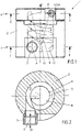
- a powder distribution device 1 is shown, as can be used to distribute a powder to a number of supply points.
- the powder is fed in via a line (not shown) and is in compressed air as a load.
- the introduction of the powder into the air takes place with a device such as that from the above-mentioned DE 10 2016 106 052 A1 is known, to which reference is made in this respect.
- the powder distribution device 1 has an essentially cylindrical housing 2 which extends along a longitudinal axis L.
- FIG. At a first position 7 of the longitudinal axis, i.e. at a first axial point of the housing 2, there is an inlet 3, with which the powder-laden air P is supplied (see figure 2 ).
- the flow path 9 has a radially outer boundary 12 formed by a corresponding cylindrical recess inside the housing. Furthermore, the flow path 9 has a radially inner boundary 11 which is formed by a wall element 10 which is located coaxially to the longitudinal axis L in the housing 2 .
- the wall element has a conical shape. The axis of rotation of the cone and the longitudinal axis L are identical.
- the area of the flow path 9 decreases in a section perpendicular to the longitudinal axis L of the housing 2 as you progress from the first position 7 to the second position 8, with this being continuous in the exemplary embodiment and over the entire extent from the first position 7 to to the second position 8 takes place.
- the inlet 3 comprises a tubular section having an inlet axis A. This lies in a plane that is perpendicular to the longitudinal axis L.
- the inlet axis A enters the flow path 9 tangentially, which is determined by the distance a between the inlet axis A and the longitudinal axis L in figure 2 is marked.
- the three outlets 4, 5 and 6 are evenly distributed around the circumference of the housing 2 (ie each offset by an angle of 120°), the outlets 4, 5 and 6 also being formed by tubular sections which have respective outlet axes B. Again, the outlet axes B also enter the flow path 9 tangentially, which is caused by the distance b between the outlet axis B and the longitudinal axis L in figure 3 is marked.
- the air entering via the inlet 3, which contains the powder load, is accelerated as a result of the gradually narrowing flow path (because of the conical shape of the wall element 10) due to the conditions of the continuity equation and reaches the upper area of the housing, i.e. in the area of the three outlets 4 , 5 and 6 to the same ones, where there is automatically an even distribution of the output of the powder P at all three outlets 4, 5 and 6, as explained above.
- the flow path of the air loaded with powder is in figure 1 and in figure 3 indicated schematically with arrows.
Landscapes
- Engineering & Computer Science (AREA)
- Mechanical Engineering (AREA)
- Nozzles (AREA)
- Coating Apparatus (AREA)
Abstract
Description
- Die Erfindung betrifft eine Pulververteilvorrichtung zur Verteilung pulverförmiger Medien, umfassend ein Gehäuse mit einer Längsachse, einen Einlass für den Einlass von mit Pulver beladener Luft und mindestens zwei Auslässe für den Auslass der mit Pulver beladenen Luft.
- Für verschiedene technische Anwendungen wird Pulver benötigt, welches zu einer Bearbeitungs- oder Verbrauchsstelle geleitet werden muss. Dabei wird mit einer Pulverfördervorrichtung zunächst das Pulver in einen Luftstrom eingebracht. Eine solche Vorrichtung ist aus der
DE 10 2016 106 052 A1 bekannt. Mit ihr ist es möglich, Pulver über gewisse Förderstrecken zu fördern. Das zu fördernde Pulver kann dabei für die verschiedensten Anwendungen vorgesehen sein. Abgesehen von allgemeinen Anwendungen kann beispielsweise eine Dosierung des Pulvers zwecks Auftragens auf technische Oberflächen in Betracht kommen. Weiterhin kann Glaspulver als Schmierstoff auf die Oberfläche von Werkstücken aufgebracht werden, um diese strangzupressen. Weiterhin kommt der Auftrag von Desoxidationspulvermischungen auf heiße Werkstückoberflächen in Betracht. Ferner kann pulverförmiger Schmierstoff auf Werkzeugoberflächen aufgebracht werden, wobei insbesondere an Dornstangen, an Stauchdorne, an Stauchschalen und an Pressstempel gedacht ist. Schließlich sei die Aufbringung von pulverförmigen Schmierstoffen auf Werkstückoberflächen erwähnt, beispielsweise auf Rohrenden, Grobbleche oder Schmiederohlinge. - Sind mehrere Verbrauchsstellen für das Pulver vorgesehen, ist es aus ökonomischen Gründen sinnvoll, nicht separate Leitungen vorzusehen (mit jeweils separaten Pulverfördervorrichtung), sondern am Ende der Förderstrecke das Pulver auf mehrere Verbrauchsstellen zu verteilen. Das Pulver wird demgemäß am Ende der Leitung gleichmäßig und gleichzeitig auf mehrere Stellen verteilt, wobei auch größere Mengen an Pulver erforderlich sein können.
- Üblich ist es, den Pulverstrom über Y-Verteiler oder T-Verteiler auf mehrere Verbrauchsstellen zu verteilen. Ist dies nicht angebracht, kommt, wie oben angemerkt, der Einsatz mehrerer unabhängiger Pulverfördersysteme in Betracht, was allerdings entsprechend kostenintensiv ist.
- Insbesondere feine oder kompaktierbare Pulver neigen zum Anhaften an den Prallflächen der genannten Verteiler. Das unerwünschte Resultat sind ungleichmäßige Fördermengen in den einzelnen aufgeteilten Transportsträngen, was bis hin zu Verstopfungen in den Leitungen führen kann.
- Der Erfindung liegt die Aufgabe zugrunde, eine Vorrichtung der eingangs genannten Art so fortzubilden, dass es möglich ist, mit Pulver beladene Luft, die über den Einlass der Vorrichtung zugeführt wird, auf mehrere Auslässe möglichst gleichmäßig zu verteilen.
- Die Lösung dieser Aufgabe durch die Erfindung ist dadurch gekennzeichnet, dass der Einlass an einer ersten Position der Längsachse des Gehäuses angeordnet ist und dass die Auslässe an einer zweiten Position der Längsachse des Gehäuses angeordnet sind, wobei sich die zweite Position von der ersten Position unterscheidet, wobei im Inneren des Gehäuses ein Strömungsweg für die mit Pulver beladene Luft gebildet wird und wobei sich die Fläche des Strömungsweges in einem Schnitt senkrecht zur Längsachse des Gehäuses beim Fortschreiten von der ersten Position zur zweiten Position zumindest abschnittsweise verkleinert.
- Bevorzugt verkleinert sich die Fläche des Strömungsweges in einem Schnitt senkrecht zur Längsachse des Gehäuses beim Fortschreiten von der ersten Position zur zweiten Position stets und kontinuierlich.
- Im Inneren des Gehäuses kann ein Wandungselement angeordnet sein, welches eine innere Begrenzung des Strömungsweges bildet. Das Wandungselement weist gemäß einer bevorzugten Ausführungsform der Erfindung eine kegelförmige Außenfläche auf.
- Im Inneren des Gehäuses kann ferner eine äußere Begrenzung des Strömungsweges ausgebildet sein, die eine zylindrische Form aufweist.
- Der Einlass weist vorzugsweise einen rohrförmigen Abschnitt mit einer Einlassachse auf oder ist als solcher ausgebildet, wobei die Einlassachse in einer Ebene liegt, die senkrecht auf der Längsachse des Gehäuses steht, wobei die Einlassachse und die Längsachse einen Abstand voneinander aufweisen. Die Einlassachse trifft dabei bevorzugt in einem Schnitt senkrecht zur Längsachse tangential auf den ringförmig ausgebildeten Strömungsweg.
- Entsprechend kann vorgesehen sein, dass die Auslässe einen rohrförmigen Abschnitt mit einer Auslassachse aufweisen oder als solche ausgebildet sind, wobei die Auslassachse in einer Ebene liegt die senkrecht auf der Längsachse des Gehäuses steht, wobei die Auslassachse und die Längsachse einen Abstand voneinander aufweisen. Die Auslassachse trifft wiederum bevorzugt in einem Schnitt senkrecht zur Längsachse tangential auf den ringförmig ausgebildeten Strömungsweg.
- Bevorzugt sind mindestens drei Auslässe angeordnet.
- Die Auslässe sind bevorzugt äquidistant um den Umfang des Gehäuses herum angeordnet.
- Das Gehäuse weist bevorzugt eine im wesentlichen zylindrische Außenkontur auf.
- Die vorgeschlagene Vorrichtung erlaubt zunächst generell die Reduzierung des nötigen Anlagenaufwands, indem separate Fördervorrichtungen eingespart werden können. Dennoch ist es möglich, ein großflächiges und gleichmäßiges Aufbringen technischer Pulver zu bewerkstelligen, beispielsweise auf heiße Oberflächen, um Zunderbildung zu verhindern oder eine Schmierfilmbildung für einen nachfolgenden Prozess (Walzprozess) zu ermöglichen, was insbesondere bei Blechen, Platten, Bändern und Profilen relevant ist.
- Ähnlich wie bei einem Zyklon wird das Pulver-Luft-Gemisch, kommend von der Dosiervorrichtung, bevorzugt tangential in eine Kammer eingeblasen und dadurch in Rotation versetzt. Auf seinem Weg zu den Auslässen reduziert sich das Kammervolumen (welches den Strömungsweg des Gemisches bildet), wodurch die Rotationsgeschwindigkeit des Gemisches vergrößert wird. Am oberen Ende der Kammer befinden sich die Auslässe, die wiederum bevorzugt tangential auf die Kammer hin ausgerichtet sind. Die Auslässe haben dabei jeweils einen gleichen Querschnitt.
- Sobald das Pulver-Luft-Gemisch den ersten Auslass erreicht, strömt es dort in die Leitung hinein, wodurch der Gegendruck in dieser Leitung ansteigt. Dadurch fließt das nachfolgende Gemisch zum nächsten Auslass, in dem noch ein geringerer Gegendruck herrscht. In dieser Zeit fließt jedoch das Pulver-Luft-Gemisch im ersten Auslass weiter, so dass sich hier der Gegendruck wieder vermindert und somit weiteres Pulver dort eingetragen werden kann. Dieses Prinzip gilt für alle Auslässe in gleicher Weise, so dass mit der vorgeschlagenen Ausgestaltung erreicht werden kann, dass gleiche Mengen Gemisch pro Zeit ausgetragen bzw. verteilt werden.
- Durch den Einsatz effektiver Pulverfördervorrichtungen mit Venturidüse (s. hierzu die bereits genannte Druckschrift
DE 10 2016 106 052 A1 ) kann ein breiter Bereich an Anwendungsfällen befriedigt werden. Insbesondere können große Pulverströme realisiert werden, mit denen beispielsweise große Oberflächen beschichtet werden können. - Der Auftrag des Pulvers kann somit gleichmäßig und schnell erfolgen und die Prozesssicherheit dabei erhöht werden.
- Hierdurch ergeben sich in verschiedenen Bereichen insbesondere der Massivumformung neue Möglichkeiten der Schmierung. Üblicherweise wird hier das Werkzeug bislang gekühlt und geschmiert, da die heißen Oberflächen der Werkstücke (infolge des Leidenfrost-Effekts) nicht mit flüssigen Schmierstoffen beaufschlagt werden können. Sofern es möglich ist, werden daher die Werkzeuge hier gekühlt und anschließend geschmiert.
- Bei Einsatz von Pulver (bei dem der Leidensfrost-Effekt nicht auftritt) ergeben sich somit neue Möglichkeiten. Das Werkstück wird demgemäß mit Pulver behandelt, welches bereits schmierende Eigenschaften aufweisen kann, so dass die Fertigung entsprechend vereinfacht werden kann.
- Ein derartiges Vorgehen ist beispielsweise bei halbwarmen Schmiedeprozessen bekannt, bei dem das Billet vorgraphitiert wird. Es wird auf ca. 120 °C erwärmt, durchläuft dann ein Graphit-Wasser-Bad und kann nach der Trocknung dann dem Schmiedeprozess zugeführt werden. Ähnliches gilt auch für Pressbolzen beim Strangpressen, die z. B. mit einer Slurry vorbehandelt werden. Es handelt sich dabei jedoch stets um Wasser-Schmierstoff-Mischungen, bei denen das Wasser vor dem eigentlichen Umformvorgang verdampft sein muss.
- Mit Hilfe der Pulver-Auftragung kann ein Werkstück im Prozess direkt mit einem Schmierstoff oder einem Desoxidationsschutz (oder beidem) direkt beschichtet werden. Ein Zwischenschritt in Form einer Vorerwärmung oder Trocknung entfällt demgemäß.
- Voraussetzung dafür ist allerdings eine effektive Versorgung mit Pulver, die durch die vorgeschlagene Vorrichtung sichergestellt wird.
- Ein genaues Dosieren des Pulvers kann beispielsweise durch Schneckenförderer oder Scheibenförderer erfolgen. Damit kann die Aufbringung von Pulver pro Zeit (also in Gramm/Sekunde) auf eine zu versorgende Oberfläche präzise erfolgen, wobei beispielsweise die Schichtdicke auf der Oberfläche reproduzierbar eingestellt werden kann.
- Namentlich können mit der vorgeschlagenen Vorrichtung mehrere Versorgungsstellen (Pulveraustritte) gleichmäßig versorgt werden.
- Somit ist insbesondere eine reproduzierbare Schmierung heißer Oberflächen mit Pulver möglich. Es kann, wie gesagt, eine Verminderung aufwendiger Kühlprozesse für Werkzeuge realisiert werden, was erforderlich ist, damit flüssiger Schmierstoff auf der Oberfläche anhaftet. Weiterhin ist der Ersatz von Flüssigschmierung, beispielsweise im Falle von Schmiedepressen oder Stauchpressen, möglich, gleichermaßen auch die Vermeidung von Zunderbildung beim Warmumformen durch Auftrag eines Pulvers, welches die Bildung von Zunder verhindert.
- Im Zusammenhang mit der vorliegenden Erfindung wird von mit Pulver beladener Luft gesprochen. In diesem Zusammenhang sei folgendes angemerkt:
Der typische Anwendungsfall ist der, bei dem Druckluft zur Förderung des Pulvers eingesetzt wird. Natürlich kann gleichermaßen, ohne den Umfang der vorliegenden Erfindung zu verlassen, auch ein anderes Fördergas zum Einsatz kommen, wozu beispielsweise auf Stickstoff hingewiesen wird, welcher sich gleichermaßen gut zur Nutzung der vorliegenden Erfindung eignet. - Betreffend das hier genannte Pulver sei angemerkt, dass bei der Verwendung dieser Nomenklatur keine Einschränkung betreffend die Partikelgröße des zu fördernden Materials gemeint ist. Beispielsweise kann Glaspulver, welches sich auch mit dem erfindungsgemäßen Vorschlag bestens fördern lässt, Partikel haben, die 1 mm oder größer sind. Insofern sind im vorliegenden Falle unter Pulver auch solche Materialien zu verstehen, die man alternativ auch als Granulat bezeichnen könnte.
- In der Zeichnung ist ein Ausführungsbeispiel der Erfindung dargestellt. Es zeigen:
- Fig. 1
- eine Pulververteilvorrichtung gemäß der Erfindung in der geschnittenen Seitenansicht,
- Fig. 2
- den Schnitt C-D gemäß
Fig. 1 und - Fig. 3
- den Schnitt E-F gemäß
Fig. 1 . - In
Figur 1 ist eine Pulververteilvorrichtung 1 dargestellt, wie sie zum Verteilen eines Pulvers auf mehrere Versorgungsstellen eingesetzt werden kann. Das Pulver wird dabei über eine (nicht dargestellte) Leitung zugeführt und befindet sich als Fracht in Druckluft. Die Einbringung des Pulvers in die Luft erfolgt mit einer Vorrichtung, wie sie aus der oben genanntenDE 10 2016 106 052 A1 bekannt ist, worauf insoweit Bezug genommen wird. - Die Pulververteilvorrichtung 1 weist ein im wesentlichen zylindrisches Gehäuse 2 auf, welche sich entlang einer Längsachse L erstreckt. An einer ersten Position 7 der Längsachse, also an einer ersten axialen Stelle des Gehäuses 2, befindet sich ein Einlass 3, mit dem die mit Pulver beladene Luft P zugeführt wird (s. hierzu
Figur 2 ). An einer zweiten Position 8, also an einer zweiten axialen Stelle des Gehäuses 2, befinden sich im Ausführungsbeispiel drei Auslässe 4, 5 und 6. Ziel ist es, das über den Einlass 3 zugeführte Pulver möglichst gleichmäßig und gleichzeitig über die drei Auslässe 4, 5 und 6 auszubringen und nicht weiter dargestellten Verbrauchsstellen zuzuführen. - Im Inneren des Gehäuses 2 ist ein Strömungsweg 9 für die mit Pulver beladene Luft P ausgebildet. Der Strömungsweg 9 hat eine radial äußere Begrenzung 12, die durch eine entsprechende zylindrische Ausnehmung im Inneren des Gehäuses gebildet wird. Des weiteren hat der Strömungsweg 9 eine radial innere Begrenzung 11, die durch ein Wandungselement 10 gebildet wird, welches sich koaxial zur Längsachse L im Gehäuse 2 befindet. Das Wandungselement hat im Ausführungsbeispiel eine kegelförmliche Gestalt. Die Rotationsachse des Kegels und die Längsachse L sind identisch.
- Wesentlich ist dabei, dass sich die Fläche des Strömungsweges 9 in einem Schnitt senkrecht zur Längsachse L des Gehäuses 2 beim Fortschreiten von der ersten Position 7 zur zweiten Position 8 verkleinert, wobei dies im Ausführungsbeispiel kontinuierlich und über die gesamte Erstreckung von der ersten Position 7 bis zur zweiten Position 8 erfolgt.
- Die Anordnung und Ausrichtung des Einlasses 3 bzw. der Auslässe 4, 5 und 6 ist in den
Figuren 2 bzw. 3 dargestellt. - Wie aus
Figur 2 gesehen werden kann, umfasst der Einlass 3 einen rohrartigen Abschnitt, der eine Einlassachse A aufweist. Diese liegt in einer Ebene, die senkrecht auf der Längsachse L steht. Darüber hinaus tritt die Einlassachse A tangential in den Strömungsweg 9 ein, was durch den Abstand a zwischen der Einlassachse A und der Längsachse L inFigur 2 markiert ist. - Analoges gilt für die drei Auslässe 4, 5 und 6, wie es aus
Figur 3 hervorgeht. Die drei Auslässe 4, 5 und 6 sind um den Umfang des Gehäuses 2 herum gleichmäßig verteilt angeordnet (also jeweils um einen Winkel von 120° versetzt), wobei die Auslässe 4, 5 und 6 ebenfalls durch rohrförmige Abschnitte gebildet werden, die jeweilige Auslassachsen B haben. Wiederum treten auch die Auslassachsen B tangential in den Strömungsweg 9 ein, was durch den Abstand b zwischen der Auslassachse B und der Längsachse L inFigur 3 markiert ist. - Die über den Einlass 3 eintretende Luft, die die Pulverfracht beinhaltet, wird infolge des sich allmählich verengenden Strömungsweg (wegen der kegelförmigen Gestalt des Wandungselements 10) aufgrund der Gegebenheiten der Kontinuitätsgleichung beschleunigt und gelangt im oberen Bereich des Gehäuses, d. h. im Bereich der drei Auslässe 4, 5 und 6 zu denselben, wo sich automatisch eine gleichmäßige Verteilung der Ausbringung des Pulvers P an allen drei Auslässen 4, 5 und 6 ergibt, wie es oben erläutert wurde. Der Strömungsweg der mit Pulver beladenen Luft ist in
Figur 1 und inFigur 3 mit Pfeilen schematisch angedeutet. - Somit wird ohne hohen apparativen Aufwand (und namentlich ohne separate Dosiersysteme für die drei Entnahmestellen für Pulver) eine gleichmäßige Menge Pulver pro Zeit ausgebracht.
-
- 1
- Pulververteilvorrichtung
- 2
- Gehäuse
- 3
- Einlass
- 4
- Auslass
- 5
- Auslass
- 6
- Auslass
- 7
- erste Position
- 8
- zweite Position
- 9
- Strömungsweg
- 10
- Wandungselement
- 11
- innere Begrenzung
- 12
- äußere Begrenzung
- L
- Längsachse
- A
- Einlassachse
- a
- Abstand Einlassachse - Längsachse
- B
- Auslassachse
- b
- Abstand Auslassachse - Längsachse
- P
- mit Pulver beladene Luft
Claims (8)
- Pulververteilvorrichtung (1) zur Verteilung pulverförmiger Medien, umfassend ein Gehäuse (2) mit einer Längsachse (L), einen Einlass (3) für den Einlass von mit Pulver beladener Luft (P) und mindestens zwei Auslässe (4, 5, 6) für den Auslass der mit Pulver beladenen Luft (P), wobei der Einlass (3) an einer ersten Position (7) der Längsachse (L) des Gehäuses (2) angeordnet ist und dass die Auslässe (4, 5, 6) an einer zweiten Position (8) der Längsachse (L) des Gehäuses (2) angeordnet sind, wobei sich die zweite Position (8) von der ersten Position (7) unterscheidet, wobei im Inneren des Gehäuses (2) ein Strömungsweg (9) für die mit Pulver beladene Luft (P) gebildet wird,
dadurch gekennzeichnet,dass sich die Fläche des Strömungsweges (9) in einem Schnitt senkrecht zur Längsachse (L) des Gehäuses (2) beim Fortschreiten von der ersten Position (7) zur zweiten Position (8) zumindest abschnittsweise verkleinert,wobei der Einlass (3) einen rohrförmigen Abschnitt mit einer Einlassachse (A) aufweist oder als solcher ausgebildet ist, wobei die Einlassachse (A) in einer Ebene liegt, die senkrecht auf der Längsachse (L) des Gehäuses (2) steht, wobei die Einlassachse (A) und die Längsachse (L) einen Abstand (a) voneinander aufweisen, wobei die Einlassachse (A) in einem Schnitt senkrecht zur Längsachse (L) tangential auf den ringförmig ausgebildeten Strömungsweg (9) trifft, undwobei die Auslässe (4, 5, 6) einen rohrförmigen Abschnitt mit einer Auslassachse (B) aufweisen oder als solche ausgebildet sind, wobei die Auslassachse (B) in einer Ebene liegt, die senkrecht auf der Längsachse (L) des Gehäuses (2) steht, wobei die Auslassachse (B) und die Längsachse (L) einen Abstand (b) voneinander aufweisen, wobei die Auslassachse (B) in einem Schnitt senkrecht zur Längsachse (L) tangential auf den ringförmig ausgebildeten Strömungsweg (9) trifft. - Pulververteilvorrichtung nach Anspruch 1, dadurch gekennzeichnet, dass sich die Fläche des Strömungsweges (9) in einem Schnitt senkrecht zur Längsachse (L) des Gehäuses (2) beim Fortschreiten von der ersten Position (7) zur zweiten Position (8) stets und kontinuierlich verkleinert.
- Pulververteilvorrichtung nach Anspruch 1 oder 2, dadurch gekennzeichnet, dass im Inneren des Gehäuses (2) ein Wandungselement (10) angeordnet ist, welches eine innere Begrenzung (11) des Strömungsweges (9) bildet.
- Pulververteilvorrichtung nach Anspruch 3, dadurch gekennzeichnet, dass das Wandungselement (10) eine kegelförmige Außenfläche aufweist.
- Pulververteilvorrichtung nach einem der Ansprüche 1 bis 4, dadurch gekennzeichnet, dass im Inneren des Gehäuses (2) eine äußere Begrenzung (12) des Strömungsweges (9) ausgebildet ist, die eine zylindrische Form aufweist.
- Pulververteilvorrichtung nach einem der Ansprüche 1 bis 5, dadurch gekennzeichnet, dass mindestens drei Auslässe (4, 5, 6) angeordnet sind.
- Pulververteilvorrichtung nach einem der Ansprüche 1 bis 6, dadurch gekennzeichnet, dass die Auslässe (4, 5, 6) äquidistant um den Umfang des Gehäuses (2) herum angeordnet sind.
- Pulververteilvorrichtung nach einem der Ansprüche 1 bis 7, dadurch gekennzeichnet, dass das Gehäuse (2) eine im wesentlichen zylindrische Außenkontur aufweist.
Applications Claiming Priority (1)
| Application Number | Priority Date | Filing Date | Title |
|---|---|---|---|
| DE102020214116.9A DE102020214116A1 (de) | 2020-11-10 | 2020-11-10 | Pulververteilvorrichtung zur Verteilung pulverförmiger Medien |
Publications (2)
| Publication Number | Publication Date |
|---|---|
| EP3995422A1 true EP3995422A1 (de) | 2022-05-11 |
| EP3995422B1 EP3995422B1 (de) | 2023-08-09 |
Family
ID=78413591
Family Applications (1)
| Application Number | Title | Priority Date | Filing Date |
|---|---|---|---|
| EP21201476.5A Active EP3995422B1 (de) | 2020-11-10 | 2021-10-07 | Pulververteilvorrichtung zur verteilung pulverförmiger medien |
Country Status (3)
| Country | Link |
|---|---|
| EP (1) | EP3995422B1 (de) |
| DE (1) | DE102020214116A1 (de) |
| ES (1) | ES2964187T3 (de) |
Citations (5)
| Publication number | Priority date | Publication date | Assignee | Title |
|---|---|---|---|---|
| US2989777A (en) * | 1957-06-04 | 1961-06-27 | Surf Chemical Inc | Dry powder extruding apparatus and methods for producing polytetrafluoroethylene articles |
| US4085776A (en) * | 1976-01-29 | 1978-04-25 | Derrick Manufacturing Corporation | Flow divider |
| DE3305079C1 (de) * | 1983-02-14 | 1984-06-28 | Hoechst Ag, 6230 Frankfurt | Rohrweiche fuer Rohrleitungen zur Foerderung von Feststoffen oder Dispersionen |
| DE69829747T2 (de) * | 1997-05-25 | 2006-03-16 | Vortex Ecological Technologies Ltd. | Zyklonabscheider |
| DE102016106052A1 (de) | 2015-11-10 | 2017-05-11 | Sms Group Gmbh | Venturi-Düse, Pulvereinblasvorrichtung sowie Verfahren zum Betrieb einer Pulvereinblasvorrichtung |
Family Cites Families (5)
| Publication number | Priority date | Publication date | Assignee | Title |
|---|---|---|---|---|
| US3204942A (en) | 1963-02-18 | 1965-09-07 | Babcock & Wilcox Co | Distributor for pneumatically transported particle-form material |
| US4024822A (en) | 1975-12-22 | 1977-05-24 | Arthur Ross | Pneumatic seeder assembly |
| US4832539A (en) | 1983-04-20 | 1989-05-23 | The Babcock & Wilcox Company | Distribution of gas entrained particles |
| DE3721948A1 (de) | 1987-07-03 | 1989-01-12 | Mann & Hummel Filter | Verfahren und vorrichtung zum gleichmaessigen verteilen von pneumatischen foerderstroemen |
| DE3815864A1 (de) | 1988-05-09 | 1989-11-23 | Krupp Polysius Ag | Vorrichtung zur aufteilung eines mit feststoff beladenen gasstromes |
-
2020
- 2020-11-10 DE DE102020214116.9A patent/DE102020214116A1/de active Pending
-
2021
- 2021-10-07 ES ES21201476T patent/ES2964187T3/es active Active
- 2021-10-07 EP EP21201476.5A patent/EP3995422B1/de active Active
Patent Citations (5)
| Publication number | Priority date | Publication date | Assignee | Title |
|---|---|---|---|---|
| US2989777A (en) * | 1957-06-04 | 1961-06-27 | Surf Chemical Inc | Dry powder extruding apparatus and methods for producing polytetrafluoroethylene articles |
| US4085776A (en) * | 1976-01-29 | 1978-04-25 | Derrick Manufacturing Corporation | Flow divider |
| DE3305079C1 (de) * | 1983-02-14 | 1984-06-28 | Hoechst Ag, 6230 Frankfurt | Rohrweiche fuer Rohrleitungen zur Foerderung von Feststoffen oder Dispersionen |
| DE69829747T2 (de) * | 1997-05-25 | 2006-03-16 | Vortex Ecological Technologies Ltd. | Zyklonabscheider |
| DE102016106052A1 (de) | 2015-11-10 | 2017-05-11 | Sms Group Gmbh | Venturi-Düse, Pulvereinblasvorrichtung sowie Verfahren zum Betrieb einer Pulvereinblasvorrichtung |
Also Published As
| Publication number | Publication date |
|---|---|
| ES2964187T3 (es) | 2024-04-04 |
| DE102020214116A1 (de) | 2022-05-12 |
| EP3995422B1 (de) | 2023-08-09 |
Similar Documents
| Publication | Publication Date | Title |
|---|---|---|
| DE69006913T2 (de) | Vorrichtung zum kontinuierlichen Strangpressen. | |
| DE69804959T2 (de) | Verfahren und vorrichtung zum transport von schüttgut, körnigem material oder pulverförmigem material | |
| EP0676280A1 (de) | Verfahren und Vorrichtung zum Aufbringen von pulverförmigem Schmier- oder Trennmittel auf die Presswerkzeuge in Tablettiermaschinen | |
| EP0581208B1 (de) | Vorrichtung zum Herstellen eines Metall-Kunststoff-Verbundrohres | |
| WO2017207622A1 (de) | Schmiervorrichtung zum aufbringen eines schmiermittels beim walzen eines walzgutes | |
| EP3995422B1 (de) | Pulververteilvorrichtung zur verteilung pulverförmiger medien | |
| CH652052A5 (de) | Verfahren und einrichtung zur herstellung einer seitennahtlosen metalltube. | |
| EP0013012A1 (de) | Vorrichtung zur Beschichtung von metallischem Umformgut mit einem Schmierstoff | |
| WO2022194454A1 (de) | Pulverfördervorrichtung zur förderung pulverförmiger medien | |
| EP3636411A1 (de) | Blaskopf und verfahren zur herstellung einer mehrschichtschlauchfolie | |
| DE2554239A1 (de) | Verfahren und vorrichtung zum ummanteln eines extrudierten kernprofiles aus kunststoff | |
| DE1577805A1 (de) | Behaelterdichtung | |
| DE2015477A1 (de) | Verfahren und Vorrichtung zum Auskleiden eines Rohres mit Isolierstoff | |
| DE3714593C2 (de) | ||
| EP1748851B1 (de) | Vorrichtung und verfahren zum aufteilen einer mittels einer gasströmung transportierten viskosen flüssigkeit in mindestens zwei teilströmen | |
| DE3130925C2 (de) | ||
| DE4337944C2 (de) | Verfahren zum Betreiben eines Siphons sowie Siphon für die Papierindustrie | |
| DE102015113849B4 (de) | Vorrichtung, Verfahren und Anlage zur Herstellung einer Pressgutmatte | |
| EP1649206B1 (de) | Vorrichtung zum aufteilen eines in einer gasströmung transportierten viskosen mediums, insbesondere eines schmiermittels wie öl | |
| EP3027383A1 (de) | Verfahren zur herstellung eines mit einer verschleissschutzschicht versehenen doppelschneckenzylinders | |
| DE909334C (de) | Pressenkopf fuer Strangpressen, insbesondere fuer Kabelmantelpressen | |
| DE10295854B4 (de) | Vorrichtung zur Wärmebehandlung und hydraulischen Förderung von Walzgut | |
| EP1054738B1 (de) | Nebelgeneratorkopf | |
| DE3722913C2 (de) | ||
| DE102004055799B3 (de) | Verfahren zur Herstellung von Minen |
Legal Events
| Date | Code | Title | Description |
|---|---|---|---|
| PUAI | Public reference made under article 153(3) epc to a published international application that has entered the european phase |
Free format text: ORIGINAL CODE: 0009012 |
|
| STAA | Information on the status of an ep patent application or granted ep patent |
Free format text: STATUS: REQUEST FOR EXAMINATION WAS MADE |
|
| STAA | Information on the status of an ep patent application or granted ep patent |
Free format text: STATUS: EXAMINATION IS IN PROGRESS |
|
| 17P | Request for examination filed |
Effective date: 20211007 |
|
| AK | Designated contracting states |
Kind code of ref document: A1 Designated state(s): AL AT BE BG CH CY CZ DE DK EE ES FI FR GB GR HR HU IE IS IT LI LT LU LV MC MK MT NL NO PL PT RO RS SE SI SK SM TR |
|
| 17Q | First examination report despatched |
Effective date: 20220426 |
|
| RBV | Designated contracting states (corrected) |
Designated state(s): AL AT BE BG CH CY CZ DE DK EE ES FI FR GB GR HR HU IE IS IT LI LT LU LV MC MK MT NL NO PL PT RO RS SE SI SK SM TR |
|
| GRAP | Despatch of communication of intention to grant a patent |
Free format text: ORIGINAL CODE: EPIDOSNIGR1 |
|
| STAA | Information on the status of an ep patent application or granted ep patent |
Free format text: STATUS: GRANT OF PATENT IS INTENDED |
|
| INTG | Intention to grant announced |
Effective date: 20230309 |
|
| GRAS | Grant fee paid |
Free format text: ORIGINAL CODE: EPIDOSNIGR3 |
|
| GRAA | (expected) grant |
Free format text: ORIGINAL CODE: 0009210 |
|
| STAA | Information on the status of an ep patent application or granted ep patent |
Free format text: STATUS: THE PATENT HAS BEEN GRANTED |
|
| AK | Designated contracting states |
Kind code of ref document: B1 Designated state(s): AL AT BE BG CH CY CZ DE DK EE ES FI FR GB GR HR HU IE IS IT LI LT LU LV MC MK MT NL NO PL PT RO RS SE SI SK SM TR |
|
| REG | Reference to a national code |
Ref country code: GB Ref legal event code: FG4D Free format text: NOT ENGLISH |
|
| REG | Reference to a national code |
Ref country code: CH Ref legal event code: EP |
|
| P01 | Opt-out of the competence of the unified patent court (upc) registered |
Effective date: 20230707 |
|
| REG | Reference to a national code |
Ref country code: DE Ref legal event code: R096 Ref document number: 502021001208 Country of ref document: DE |
|
| REG | Reference to a national code |
Ref country code: IE Ref legal event code: FG4D Free format text: LANGUAGE OF EP DOCUMENT: GERMAN |
|
| REG | Reference to a national code |
Ref country code: LT Ref legal event code: MG9D |
|
| REG | Reference to a national code |
Ref country code: NL Ref legal event code: MP Effective date: 20230809 |
|
| PG25 | Lapsed in a contracting state [announced via postgrant information from national office to epo] |
Ref country code: GR Free format text: LAPSE BECAUSE OF FAILURE TO SUBMIT A TRANSLATION OF THE DESCRIPTION OR TO PAY THE FEE WITHIN THE PRESCRIBED TIME-LIMIT Effective date: 20231110 |
|
| PG25 | Lapsed in a contracting state [announced via postgrant information from national office to epo] |
Ref country code: IS Free format text: LAPSE BECAUSE OF FAILURE TO SUBMIT A TRANSLATION OF THE DESCRIPTION OR TO PAY THE FEE WITHIN THE PRESCRIBED TIME-LIMIT Effective date: 20231209 |
|
| PG25 | Lapsed in a contracting state [announced via postgrant information from national office to epo] |
Ref country code: SE Free format text: LAPSE BECAUSE OF FAILURE TO SUBMIT A TRANSLATION OF THE DESCRIPTION OR TO PAY THE FEE WITHIN THE PRESCRIBED TIME-LIMIT Effective date: 20230809 Ref country code: RS Free format text: LAPSE BECAUSE OF FAILURE TO SUBMIT A TRANSLATION OF THE DESCRIPTION OR TO PAY THE FEE WITHIN THE PRESCRIBED TIME-LIMIT Effective date: 20230809 Ref country code: PT Free format text: LAPSE BECAUSE OF FAILURE TO SUBMIT A TRANSLATION OF THE DESCRIPTION OR TO PAY THE FEE WITHIN THE PRESCRIBED TIME-LIMIT Effective date: 20231211 Ref country code: NO Free format text: LAPSE BECAUSE OF FAILURE TO SUBMIT A TRANSLATION OF THE DESCRIPTION OR TO PAY THE FEE WITHIN THE PRESCRIBED TIME-LIMIT Effective date: 20231109 Ref country code: NL Free format text: LAPSE BECAUSE OF FAILURE TO SUBMIT A TRANSLATION OF THE DESCRIPTION OR TO PAY THE FEE WITHIN THE PRESCRIBED TIME-LIMIT Effective date: 20230809 Ref country code: LV Free format text: LAPSE BECAUSE OF FAILURE TO SUBMIT A TRANSLATION OF THE DESCRIPTION OR TO PAY THE FEE WITHIN THE PRESCRIBED TIME-LIMIT Effective date: 20230809 Ref country code: LT Free format text: LAPSE BECAUSE OF FAILURE TO SUBMIT A TRANSLATION OF THE DESCRIPTION OR TO PAY THE FEE WITHIN THE PRESCRIBED TIME-LIMIT Effective date: 20230809 Ref country code: IS Free format text: LAPSE BECAUSE OF FAILURE TO SUBMIT A TRANSLATION OF THE DESCRIPTION OR TO PAY THE FEE WITHIN THE PRESCRIBED TIME-LIMIT Effective date: 20231209 Ref country code: HR Free format text: LAPSE BECAUSE OF FAILURE TO SUBMIT A TRANSLATION OF THE DESCRIPTION OR TO PAY THE FEE WITHIN THE PRESCRIBED TIME-LIMIT Effective date: 20230809 Ref country code: GR Free format text: LAPSE BECAUSE OF FAILURE TO SUBMIT A TRANSLATION OF THE DESCRIPTION OR TO PAY THE FEE WITHIN THE PRESCRIBED TIME-LIMIT Effective date: 20231110 Ref country code: FI Free format text: LAPSE BECAUSE OF FAILURE TO SUBMIT A TRANSLATION OF THE DESCRIPTION OR TO PAY THE FEE WITHIN THE PRESCRIBED TIME-LIMIT Effective date: 20230809 |
|
| PG25 | Lapsed in a contracting state [announced via postgrant information from national office to epo] |
Ref country code: PL Free format text: LAPSE BECAUSE OF FAILURE TO SUBMIT A TRANSLATION OF THE DESCRIPTION OR TO PAY THE FEE WITHIN THE PRESCRIBED TIME-LIMIT Effective date: 20230809 |
|
| REG | Reference to a national code |
Ref country code: ES Ref legal event code: FG2A Ref document number: 2964187 Country of ref document: ES Kind code of ref document: T3 Effective date: 20240404 |
|
| PG25 | Lapsed in a contracting state [announced via postgrant information from national office to epo] |
Ref country code: SM Free format text: LAPSE BECAUSE OF FAILURE TO SUBMIT A TRANSLATION OF THE DESCRIPTION OR TO PAY THE FEE WITHIN THE PRESCRIBED TIME-LIMIT Effective date: 20230809 Ref country code: RO Free format text: LAPSE BECAUSE OF FAILURE TO SUBMIT A TRANSLATION OF THE DESCRIPTION OR TO PAY THE FEE WITHIN THE PRESCRIBED TIME-LIMIT Effective date: 20230809 Ref country code: EE Free format text: LAPSE BECAUSE OF FAILURE TO SUBMIT A TRANSLATION OF THE DESCRIPTION OR TO PAY THE FEE WITHIN THE PRESCRIBED TIME-LIMIT Effective date: 20230809 Ref country code: DK Free format text: LAPSE BECAUSE OF FAILURE TO SUBMIT A TRANSLATION OF THE DESCRIPTION OR TO PAY THE FEE WITHIN THE PRESCRIBED TIME-LIMIT Effective date: 20230809 Ref country code: CZ Free format text: LAPSE BECAUSE OF FAILURE TO SUBMIT A TRANSLATION OF THE DESCRIPTION OR TO PAY THE FEE WITHIN THE PRESCRIBED TIME-LIMIT Effective date: 20230809 Ref country code: SK Free format text: LAPSE BECAUSE OF FAILURE TO SUBMIT A TRANSLATION OF THE DESCRIPTION OR TO PAY THE FEE WITHIN THE PRESCRIBED TIME-LIMIT Effective date: 20230809 |
|
| REG | Reference to a national code |
Ref country code: DE Ref legal event code: R097 Ref document number: 502021001208 Country of ref document: DE |
|
| PG25 | Lapsed in a contracting state [announced via postgrant information from national office to epo] |
Ref country code: MC Free format text: LAPSE BECAUSE OF FAILURE TO SUBMIT A TRANSLATION OF THE DESCRIPTION OR TO PAY THE FEE WITHIN THE PRESCRIBED TIME-LIMIT Effective date: 20230809 |
|
| PLBE | No opposition filed within time limit |
Free format text: ORIGINAL CODE: 0009261 |
|
| STAA | Information on the status of an ep patent application or granted ep patent |
Free format text: STATUS: NO OPPOSITION FILED WITHIN TIME LIMIT |
|
| REG | Reference to a national code |
Ref country code: BE Ref legal event code: MM Effective date: 20231031 |
|
| PG25 | Lapsed in a contracting state [announced via postgrant information from national office to epo] |
Ref country code: LU Free format text: LAPSE BECAUSE OF NON-PAYMENT OF DUE FEES Effective date: 20231007 |
|
| PG25 | Lapsed in a contracting state [announced via postgrant information from national office to epo] |
Ref country code: LU Free format text: LAPSE BECAUSE OF NON-PAYMENT OF DUE FEES Effective date: 20231007 |
|
| 26N | No opposition filed |
Effective date: 20240513 |
|
| PG25 | Lapsed in a contracting state [announced via postgrant information from national office to epo] |
Ref country code: FR Free format text: LAPSE BECAUSE OF NON-PAYMENT OF DUE FEES Effective date: 20231009 Ref country code: SI Free format text: LAPSE BECAUSE OF FAILURE TO SUBMIT A TRANSLATION OF THE DESCRIPTION OR TO PAY THE FEE WITHIN THE PRESCRIBED TIME-LIMIT Effective date: 20230809 |
|
| PG25 | Lapsed in a contracting state [announced via postgrant information from national office to epo] |
Ref country code: BE Free format text: LAPSE BECAUSE OF NON-PAYMENT OF DUE FEES Effective date: 20231031 |
|
| PG25 | Lapsed in a contracting state [announced via postgrant information from national office to epo] |
Ref country code: IE Free format text: LAPSE BECAUSE OF NON-PAYMENT OF DUE FEES Effective date: 20231007 |
|
| PG25 | Lapsed in a contracting state [announced via postgrant information from national office to epo] |
Ref country code: IE Free format text: LAPSE BECAUSE OF NON-PAYMENT OF DUE FEES Effective date: 20231007 |
|
| PG25 | Lapsed in a contracting state [announced via postgrant information from national office to epo] |
Ref country code: BG Free format text: LAPSE BECAUSE OF FAILURE TO SUBMIT A TRANSLATION OF THE DESCRIPTION OR TO PAY THE FEE WITHIN THE PRESCRIBED TIME-LIMIT Effective date: 20230809 |
|
| PG25 | Lapsed in a contracting state [announced via postgrant information from national office to epo] |
Ref country code: BG Free format text: LAPSE BECAUSE OF FAILURE TO SUBMIT A TRANSLATION OF THE DESCRIPTION OR TO PAY THE FEE WITHIN THE PRESCRIBED TIME-LIMIT Effective date: 20230809 |
|
| PG25 | Lapsed in a contracting state [announced via postgrant information from national office to epo] |
Ref country code: CY Free format text: LAPSE BECAUSE OF FAILURE TO SUBMIT A TRANSLATION OF THE DESCRIPTION OR TO PAY THE FEE WITHIN THE PRESCRIBED TIME-LIMIT; INVALID AB INITIO Effective date: 20211007 |
|
| PG25 | Lapsed in a contracting state [announced via postgrant information from national office to epo] |
Ref country code: HU Free format text: LAPSE BECAUSE OF FAILURE TO SUBMIT A TRANSLATION OF THE DESCRIPTION OR TO PAY THE FEE WITHIN THE PRESCRIBED TIME-LIMIT; INVALID AB INITIO Effective date: 20211007 |
|
| REG | Reference to a national code |
Ref country code: CH Ref legal event code: U11 Free format text: ST27 STATUS EVENT CODE: U-0-0-U10-U11 (AS PROVIDED BY THE NATIONAL OFFICE) Effective date: 20251101 |
|
| PG25 | Lapsed in a contracting state [announced via postgrant information from national office to epo] |
Ref country code: TR Free format text: LAPSE BECAUSE OF FAILURE TO SUBMIT A TRANSLATION OF THE DESCRIPTION OR TO PAY THE FEE WITHIN THE PRESCRIBED TIME-LIMIT Effective date: 20230809 |
|
| PGFP | Annual fee paid to national office [announced via postgrant information from national office to epo] |
Ref country code: DE Payment date: 20251021 Year of fee payment: 5 |
|
| PGFP | Annual fee paid to national office [announced via postgrant information from national office to epo] |
Ref country code: AT Payment date: 20260113 Year of fee payment: 5 |
|
| PGFP | Annual fee paid to national office [announced via postgrant information from national office to epo] |
Ref country code: IT Payment date: 20251024 Year of fee payment: 5 |
|
| PGFP | Annual fee paid to national office [announced via postgrant information from national office to epo] |
Ref country code: CH Payment date: 20251101 Year of fee payment: 5 |
|
| PGFP | Annual fee paid to national office [announced via postgrant information from national office to epo] |
Ref country code: ES Payment date: 20251216 Year of fee payment: 5 |