EP3993944B1 - Procédé de fabrication d'une paroi de pulvérisation - Google Patents
Procédé de fabrication d'une paroi de pulvérisation Download PDFInfo
- Publication number
- EP3993944B1 EP3993944B1 EP20746259.9A EP20746259A EP3993944B1 EP 3993944 B1 EP3993944 B1 EP 3993944B1 EP 20746259 A EP20746259 A EP 20746259A EP 3993944 B1 EP3993944 B1 EP 3993944B1
- Authority
- EP
- European Patent Office
- Prior art keywords
- holes
- membrane
- laser beam
- fpp
- laser
- Prior art date
- Legal status (The legal status is an assumption and is not a legal conclusion. Google has not performed a legal analysis and makes no representation as to the accuracy of the status listed.)
- Active
Links
Images
Classifications
-
- B—PERFORMING OPERATIONS; TRANSPORTING
- B05—SPRAYING OR ATOMISING IN GENERAL; APPLYING FLUENT MATERIALS TO SURFACES, IN GENERAL
- B05B—SPRAYING APPARATUS; ATOMISING APPARATUS; NOZZLES
- B05B1/00—Nozzles, spray heads or other outlets, with or without auxiliary devices such as valves, heating means
- B05B1/14—Nozzles, spray heads or other outlets, with or without auxiliary devices such as valves, heating means with multiple outlet openings; with strainers in or outside the outlet opening
-
- B—PERFORMING OPERATIONS; TRANSPORTING
- B23—MACHINE TOOLS; METAL-WORKING NOT OTHERWISE PROVIDED FOR
- B23K—SOLDERING OR UNSOLDERING; WELDING; CLADDING OR PLATING BY SOLDERING OR WELDING; CUTTING BY APPLYING HEAT LOCALLY, e.g. FLAME CUTTING; WORKING BY LASER BEAM
- B23K26/00—Working by laser beam, e.g. welding, cutting or boring
- B23K26/02—Positioning or observing the workpiece, e.g. with respect to the point of impact; Aligning, aiming or focusing the laser beam
- B23K26/06—Shaping the laser beam, e.g. by masks or multi-focusing
- B23K26/062—Shaping the laser beam, e.g. by masks or multi-focusing by direct control of the laser beam
- B23K26/0622—Shaping the laser beam, e.g. by masks or multi-focusing by direct control of the laser beam by shaping pulses
- B23K26/0624—Shaping the laser beam, e.g. by masks or multi-focusing by direct control of the laser beam by shaping pulses using ultrashort pulses, i.e. pulses of 1 ns or less
-
- B—PERFORMING OPERATIONS; TRANSPORTING
- B23—MACHINE TOOLS; METAL-WORKING NOT OTHERWISE PROVIDED FOR
- B23K—SOLDERING OR UNSOLDERING; WELDING; CLADDING OR PLATING BY SOLDERING OR WELDING; CUTTING BY APPLYING HEAT LOCALLY, e.g. FLAME CUTTING; WORKING BY LASER BEAM
- B23K26/00—Working by laser beam, e.g. welding, cutting or boring
- B23K26/02—Positioning or observing the workpiece, e.g. with respect to the point of impact; Aligning, aiming or focusing the laser beam
- B23K26/06—Shaping the laser beam, e.g. by masks or multi-focusing
- B23K26/064—Shaping the laser beam, e.g. by masks or multi-focusing by means of optical elements, e.g. lenses, mirrors or prisms
- B23K26/066—Shaping the laser beam, e.g. by masks or multi-focusing by means of optical elements, e.g. lenses, mirrors or prisms by using masks
-
- B—PERFORMING OPERATIONS; TRANSPORTING
- B23—MACHINE TOOLS; METAL-WORKING NOT OTHERWISE PROVIDED FOR
- B23K—SOLDERING OR UNSOLDERING; WELDING; CLADDING OR PLATING BY SOLDERING OR WELDING; CUTTING BY APPLYING HEAT LOCALLY, e.g. FLAME CUTTING; WORKING BY LASER BEAM
- B23K26/00—Working by laser beam, e.g. welding, cutting or boring
- B23K26/02—Positioning or observing the workpiece, e.g. with respect to the point of impact; Aligning, aiming or focusing the laser beam
- B23K26/06—Shaping the laser beam, e.g. by masks or multi-focusing
- B23K26/067—Dividing the beam into multiple beams, e.g. multi-focusing
- B23K26/0676—Dividing the beam into multiple beams, e.g. multi-focusing into dependently operating sub-beams, e.g. an array of spots with fixed spatial relationship or for performing simultaneously identical operations
-
- B—PERFORMING OPERATIONS; TRANSPORTING
- B23—MACHINE TOOLS; METAL-WORKING NOT OTHERWISE PROVIDED FOR
- B23K—SOLDERING OR UNSOLDERING; WELDING; CLADDING OR PLATING BY SOLDERING OR WELDING; CUTTING BY APPLYING HEAT LOCALLY, e.g. FLAME CUTTING; WORKING BY LASER BEAM
- B23K26/00—Working by laser beam, e.g. welding, cutting or boring
- B23K26/36—Removing material
- B23K26/38—Removing material by boring or cutting
- B23K26/382—Removing material by boring or cutting by boring
- B23K26/389—Removing material by boring or cutting by boring of fluid openings, e.g. nozzles, jets
-
- B—PERFORMING OPERATIONS; TRANSPORTING
- B23—MACHINE TOOLS; METAL-WORKING NOT OTHERWISE PROVIDED FOR
- B23K—SOLDERING OR UNSOLDERING; WELDING; CLADDING OR PLATING BY SOLDERING OR WELDING; CUTTING BY APPLYING HEAT LOCALLY, e.g. FLAME CUTTING; WORKING BY LASER BEAM
- B23K26/00—Working by laser beam, e.g. welding, cutting or boring
- B23K26/36—Removing material
- B23K26/40—Removing material taking account of the properties of the material involved
- B23K26/402—Removing material taking account of the properties of the material involved involving non-metallic material, e.g. isolators
-
- B—PERFORMING OPERATIONS; TRANSPORTING
- B23—MACHINE TOOLS; METAL-WORKING NOT OTHERWISE PROVIDED FOR
- B23K—SOLDERING OR UNSOLDERING; WELDING; CLADDING OR PLATING BY SOLDERING OR WELDING; CUTTING BY APPLYING HEAT LOCALLY, e.g. FLAME CUTTING; WORKING BY LASER BEAM
- B23K2103/00—Materials to be soldered, welded or cut
- B23K2103/30—Organic materials
- B23K2103/42—Plastics other than composite materials
Definitions
- the present invention relates to a method of manufacturing a spray wall pierced with an array of holes through which a fluid product under pressure passes so as to be sprayed into fine droplets as described in the preamble of claim 1 (see, for example, US6295986 B1 ).
- the spray wall is generally mounted in a dispensing head which is supplied with fluid product under pressure by a dispensing member, such as a pump or a valve.
- the dispensing head can be in the form of a pusher on which a user can press using a finger (generally the index finger) to actuate the pump or the valve so as to discharge fluid product through the spray wall where it will be sprayed in fine droplets.
- This type of fluid product dispensing head is frequently used in the fields of perfumery, cosmetics or even pharmacy.
- a nozzle comprising a spray wall pierced with several spray holes of diameter substantially or perfectly identical, of the order of 1 to 100 ⁇ m, with a tolerance of 20%.
- a spray wall would generate a spray whose droplet size is relatively homogeneous.
- the wall is curved and the holes are then divergent. The opening angle of the spray remains small, however. This document is silent as to the technique for forming the holes.
- the spray wall is of constant thickness, but curved.
- the holes were drilled perpendicular to the plane of the wall, while the wall was still flat.
- the curvature of the wall allows the holes to diverge, once the wall is curved. It is specified that the holes have, after curving, a constant section over their entire length. It is not explained in this document how, or at what time, the drilled flat wall is curved. In the drawings, the curvature of the curving is small, so that the opening angle of the spray is small. This document provides for the holes to be made by laser or engraving.
- the present invention aims to define a laser manufacturing method for a spray wall, which is very fast and which guarantees strict identity and/or precision of the holes.
- step b) comprises directing the laser beam onto a mask capable of blocking or absorbing a portion of the laser beam and allowing another portion of the laser beam to pass through or reflect in the form of the partial laser beam array.
- the mask may be in the form of a sieve or grid, or in the form of a partially reflecting mirror. The precision of the mask will have a strong influence on the identity of the holes drilled in the membrane.
- several series of holes can be made consecutively with masks, the number of holes per series being less than about 30, advantageously of the order of 20 and preferably of the order of 10.
- the fewer holes per series the less powerful the laser beam needs to be.
- the quality of the drilling is better with a small number of holes, because they can be further apart from each other. Two nearby holes are affected by a large amount of energy concentrated in a reduced surface area.
- At least one of the masks of a series is different from the masks of the other series.
- a total network of holes can be decomposed into complementary subnetworks, which may be identical or different. This makes it possible to distance the holes drilled simultaneously from each other to guarantee their quality.
- the holes drilled simultaneously may be at least 20 ⁇ m apart and preferably about 70 ⁇ m apart, or even 100 ⁇ m to 200 ⁇ m apart.
- the spray wall can be made of polymer material, preferably PP or PBT, and have a thickness of 50 ⁇ m to 250 ⁇ m, preferably 90 to 150 ⁇ m.
- the laser beam has a wavelength in the infrared between 950 nm and 1100 nm, advantageously of the order of 1030 nm.
- the laser beam may have a pulse duration of less than 10 picoseconds, advantageously of the order of 0.26 picoseconds.
- the wavelength of 950 nm and 1100 nm and/or the pulse duration of less than 10 picoseconds for the laser beam are/are characteristics that can be implemented independently of the fact of laser drilling by implementing several partial laser beam arrays leading to several series of holes drilled consecutively with identical or different complementary masks. Individual protection could be sought for each of these two characteristics or a combination of these two characteristics.
- the partial laser beams are advantageously parallel, but they can also be convergent or divergent, for example by placing a convergent or divergent lens between the mask and the membrane to be pierced.
- the membrane is at least locally flat and can extend perpendicular to the partial laser beams.
- Each partial laser beam can thus impact the membrane in an identical manner. It is also possible to modulate each partial laser beam in a differentiated manner.
- the membrane is at least locally flat and can extend obliquely to the partial laser beams.
- the membrane is curved and has an axis or plane of symmetry that may be parallel to or coincident with the partial laser beams.
- curved encompasses all non-completely planar shapes, such as convex or concave domes, cones, pyramids, bends, folds, etc.
- all of the holes in the spray wall can be drilled simultaneously by an array of partial laser beams from a single laser source.
- all of the holes in the spray wall can be drilled, advantageously simultaneously, by several partial laser beam networks coming from several laser sources respectively.
- a first series of holes can be drilled with a given inclination and/or size and a second series of holes with another inclination and/or size.
- the holes can have a passage section of the order of 0.5 ⁇ m2 to 700 ⁇ m2, advantageously of 10 ⁇ m2 to 300 ⁇ m2 and preferably of 50 ⁇ m2 to 200 ⁇ m2.
- the network of holes can have a cumulative passage section of the order of 1000 ⁇ m2 to 20000 ⁇ m2, advantageously of 3000 ⁇ m2 to 8000 ⁇ m2 and preferably of 3500 ⁇ m2 to 6500 ⁇ m2. It should be noted that these selections of passage section values (of each hole and of all the holes) are characteristics that can be implemented independently of the manufacturing process of the spray wall. They can therefore be protected in themselves, possibly as part of a push button mounted on a pump or a valve.
- the spirit of the invention is based on masking, dividing, filtering or breaking up a laser beam to create a plurality of partial beams which are parallel to each other and which will strike a perpendicular or inclined flat membrane and/or a curved membrane to pierce holes in it for spraying fluid product.
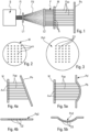
- the micro-drilling system firstly comprises a laser source S which is capable of producing an initial laser beam Fi which is directed towards a mask M, which is an essential element of the invention.
- the initial beam Fi can directly reach the mask M.
- the initial beam Fi can first pass through a first diverging lens L1 so as to obtain a diverging beam Fd which then passes through a converging lens L2 so as to obtain a widened parallel laser beam F which will impact the mask M.
- the laser beams between the source S and the mask M can still be deflected using the mirrors.
- the function of the mask M is to conform the laser beam F into a network of partial laser beams Fpp, which are here parallel to each other.
- the mask M can be in the form of a sieve or a grid defining passage openings A for a part of the laser beam F.
- the mask M can be made with any suitable material. It can be in the form of a dynamic modulator.
- the mask M is a through mask, in the sense that the laser beam F passes through the mask M.
- the mask could also be of the reflective or mirror type, reflecting only part of the laser beam F.
- the mask M is fixed during the laser micro-drilling operation. Alternatively, it is possible to move the mask M to make holes of complex shapes in the membrane P0. Regardless of the type of mask, a network of parallel partial laser beams Fpp is created, which will impact the membrane P0 to drill micro-holes O1 in it.
- FIG. 2 shows the mask M with its passage openings A, which are here round: they could however have another shape, such as for example square, triangular, oval or even slit.
- FIG 3 shows the spray wall Pp resulting from the micro-drilling of the membrane P0.
- a network of holes O1 which is strictly identical to the network of passage openings A of the mask M.
- the membrane P0 is flat and extends perpendicularly to the parallel partial beams Fpp.
- the holes O1 correspond in size and arrangement to the network of parallel partial laser beams Fpp coming from the mask M, when it is fixed.
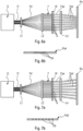
- FIG. 7a is a variant embodiment of the Figure 6a , in which the converging lens L3 has been replaced by a diverging lens L4, so as to obtain a network of diverging partial laser beams Fpd, which will impact the membrane P0 so as to pierce inclined holes in it, as can be seen in the Figure 7b , which illustrates a Pp5 spray wall pierced with divergent O5 holes.
- the various embodiments make it possible to drill micro-holes O1, O2, O3, O4, O5 in a membrane that is flat or profiled, for example curved.
- the membrane can be arranged perpendicular to the partial laser beams, as is the case of the figure 1 , or even in an inclined manner, as on the Figure 4a .
- Partial beams can be parallel, like those Fpp of the Figures 1, 4a and 5a , or even convergent like those Fpc of the Figure 6a or divergent like those Fpd of the Figure 7a .
- the membrane In the laser micro-drilling operation, the membrane is kept in a fixed and constant state. However, it can be deformed before or after the laser micro-drilling step.
- the spray wall Pp1 can be curved after micro-drilling.
- the spray wall Pp3 can be flattened or symmetrically deformed after micro-drilling. It is the same applies to the Pp4, Pp5 spray walls which can be profiled before or after drilling.
- the P0 or P0' membrane can, for example, be made of metal, such as stainless steel. It is also possible to make the membrane from a plastic material or a mixture of plastic materials.
- the membrane can also be made in the form of a laminate, comprising, for example, one or more layers of metal and one or more layers of plastic material.
- the membrane can also be made of silicon.
- the type of laser source S depends on the size of the holes to be made. For holes from 1 to 20 ⁇ m, a fixed laser by percussion will be preferred. For holes larger than 20 ⁇ m, a rotating laser by trepanation will be preferred.
- the wavelength of the light radiation can be any: it must be adapted according to the quality of drilling and the material.
- drilling stainless steel recommends the use of a laser source generating IR light radiation with a wavelength between 950 nm and 1100 nm.
- the optimum pulse duration is less than 10 picoseconds and preferably of the order of 0.26 picoseconds.
- the pulse rate is 0.1 to 70 kHz.
- the energy required is 1 to 50 mJ. It depends on the number of holes, the thickness of the surface and the number of pulses. For example, to produce 50 holes between 10 and 15 ⁇ m, an energy of between 3 and 35 mJ is required.
- the thickness of the spray membrane/wall, at the level where the holes are formed is of the order of 10 ⁇ m to 500 ⁇ m, advantageously of 30 ⁇ m to 100 ⁇ m.
- the thickness of the spray membrane/wall is preferably constant, but a variable thickness is also conceivable.
- the diameter of the spray wall Pp, at the level where the holes are formed is of the order of 0.3 mm to 5 mm.
- the diameter of the holes is of the order of 1 to 100 ⁇ m, advantageously of the order of 10 to 30 ⁇ m, and preferably of the order of 5 to 20 ⁇ m.
- the holes can have a passage section of the order of 0.5 ⁇ m2 to 700 ⁇ m2, advantageously from 10 ⁇ m2 to 300 ⁇ m2 and preferably from 50 ⁇ m2 to 200 ⁇ m2.
- the network of holes of a spray wall can have a cumulative passage section of the order of 1000 ⁇ m2 to 20000 ⁇ m2, advantageously from 3000 ⁇ m2 to 8000 ⁇ m2 and preferably from 3500 ⁇ m2 to 6500 ⁇ m2.
- 50 holes of 10 to 12 ⁇ m2 or 20 holes of 20 ⁇ m2 or 80 holes of 8 ⁇ m2 or even 300 holes of 6 ⁇ m2 can be provided.
- a spray wall having for example a diameter of approximately 1 mm
- the density of the holes per mm 2 is of the order of 40 to 80.
- the holes are not all pierced at the same time with a single mask, but in consecutive series comprising a maximum of approximately 30 holes per series. It is even preferable to reduce the number of holes to approximately 20, and preferably approximately 10.
- the term "approximately" must be understood as a tolerance of the order of 10%.
- Each series of holes uses a mask which can be identical, or on the contrary different.
- All the masks can be different from each other or different in pairs. Only one of the masks can be different from the others which are all identical.
- a dynamic mask can also be used, the passage/blocking pattern of which can be modified.
- the holes in a series, which are therefore drilled simultaneously, are spaced apart from each other by at least 20 ⁇ m and preferably about 70 ⁇ m. However, a distance of 100 ⁇ m to 200 ⁇ m is possible.
- spray walls of any shape can be produced with parallel, inclined, divergent or convergent micro-holes. All holes in the spray wall can be produced simultaneously using a single laser micro-drilling system. Alternatively, the holes can be produced in several laser micro-drilling operations, using one or two laser micro-drilling systems and a single mask or several different masks. A series of holes can be produced at the same time as another series of holes, or conversely the series of holes can be made consecutively. All the holes may have an identical configuration, for example cylindrical or truncated cone. Alternatively, two series of holes of different sizes and/or configurations may be provided.
Landscapes
- Physics & Mathematics (AREA)
- Optics & Photonics (AREA)
- Engineering & Computer Science (AREA)
- Plasma & Fusion (AREA)
- Mechanical Engineering (AREA)
- Laser Beam Processing (AREA)
- Powder Metallurgy (AREA)
- Particle Formation And Scattering Control In Inkjet Printers (AREA)
Applications Claiming Priority (2)
| Application Number | Priority Date | Filing Date | Title |
|---|---|---|---|
| FR1907335A FR3098137B1 (fr) | 2019-07-02 | 2019-07-02 | Procédé de fabrication d’une paroi de distribution |
| PCT/FR2020/051147 WO2021001628A1 (fr) | 2019-07-02 | 2020-07-01 | Procede de fabrication d'une paroi de distribution |
Publications (2)
| Publication Number | Publication Date |
|---|---|
| EP3993944A1 EP3993944A1 (fr) | 2022-05-11 |
| EP3993944B1 true EP3993944B1 (fr) | 2024-09-04 |
Family
ID=68654626
Family Applications (1)
| Application Number | Title | Priority Date | Filing Date |
|---|---|---|---|
| EP20746259.9A Active EP3993944B1 (fr) | 2019-07-02 | 2020-07-01 | Procédé de fabrication d'une paroi de pulvérisation |
Country Status (6)
| Country | Link |
|---|---|
| US (1) | US12528142B2 (es) |
| EP (1) | EP3993944B1 (es) |
| CN (1) | CN114096370A (es) |
| ES (1) | ES2989375T3 (es) |
| FR (1) | FR3098137B1 (es) |
| WO (1) | WO2021001628A1 (es) |
Families Citing this family (1)
| Publication number | Priority date | Publication date | Assignee | Title |
|---|---|---|---|---|
| US12030135B2 (en) * | 2020-10-14 | 2024-07-09 | Applied Materials, Inc. | Methods to fabricate chamber component holes using laser drilling |
Family Cites Families (20)
| Publication number | Priority date | Publication date | Assignee | Title |
|---|---|---|---|---|
| JP3211525B2 (ja) * | 1993-04-22 | 2001-09-25 | オムロン株式会社 | 薄材メッシュ、その製造方法及びその製造装置 |
| JPH11179575A (ja) * | 1997-12-16 | 1999-07-06 | Canon Inc | 光加工機及びそれを用いたオリフィスプレートの製造方法 |
| US6313435B1 (en) * | 1998-11-20 | 2001-11-06 | 3M Innovative Properties Company | Mask orbiting for laser ablated feature formation |
| US6080959A (en) * | 1999-03-12 | 2000-06-27 | Lexmark International, Inc. | System and method for feature compensation of an ablated inkjet nozzle plate |
| JP2001079677A (ja) * | 1999-09-13 | 2001-03-27 | Akoo Kiko:Kk | 合成樹脂弾性体シートの穿孔方法及び微小孔を穿設した合成樹脂弾性体シート |
| US6295986B1 (en) * | 2000-01-12 | 2001-10-02 | Aradigm Corporation | Reactive ion etching method of fabricating nozzles for aerosolized delivery of therapeutic or diagnostic agents |
| US6732943B2 (en) * | 2001-04-05 | 2004-05-11 | Aradigm Corporation | Method of generating uniform pores in thin polymer films |
| JP2003001830A (ja) * | 2001-06-22 | 2003-01-08 | Canon Inc | インクジェット記録ヘッドのインク吐出口製造方法、および該製造方法によって製造されたインク吐出口を有するインクジェット記録ヘッド |
| US7880117B2 (en) * | 2002-12-24 | 2011-02-01 | Panasonic Corporation | Method and apparatus of drilling high density submicron cavities using parallel laser beams |
| WO2004085835A1 (ja) * | 2003-03-27 | 2004-10-07 | Ngk Insulators, Ltd. | 液体噴射装置及びその製造方法 |
| DE102005000620A1 (de) * | 2005-01-03 | 2006-07-13 | Robert Bosch Gmbh | Multi-Fächerstrahl-Düse und Brennstoffeinspritzventil mit Multi-Fächerstrahl-Düse |
| DE102005010173B4 (de) | 2005-03-05 | 2006-11-16 | Aero Pump GmbH, Zerstäuberpumpen | Austrittshaube für ein Sprühgerät zum Versprühen einer hochviskosen Flüssigkeit |
| DE602006017947D1 (de) * | 2005-09-30 | 2010-12-16 | Brother Ind Ltd | Verfahren zur Herstellung einer Düsenplatte und Verfahren zur Herstellung eines Flüssigkeitstropfenstrahlgeräts |
| FR2903329B3 (fr) | 2006-07-10 | 2008-10-03 | Rexam Dispensing Systems Sas | Buse de pulverisation, dispositif de pulverisation et utilisation de ce dispositif. |
| US8016901B2 (en) * | 2008-07-14 | 2011-09-13 | Tenoroc Llc | Aerodynamic separation nozzle |
| US20100129617A1 (en) * | 2008-11-21 | 2010-05-27 | Corrigan Thomas R | Laser ablation tooling via sparse patterned masks |
| KR20130059337A (ko) * | 2010-03-30 | 2013-06-05 | 아이엠알에이 아메리카, 인코포레이티드. | 레이저 기반 재료 가공 장치 및 방법들 |
| JP5760251B2 (ja) * | 2011-04-06 | 2015-08-05 | 株式会社ブイ・テクノロジー | ガラス基板のレーザ加工装置 |
| WO2014028022A1 (en) * | 2012-08-16 | 2014-02-20 | Hewlett-Packard Development Company, L.P. | Diagonal openings in photodefinable glass |
| CN104942435B (zh) * | 2015-07-14 | 2017-07-28 | 中国工程物理研究院激光聚变研究中心 | 一种激光加工头及其进行激光加工的方法 |
-
2019
- 2019-07-02 FR FR1907335A patent/FR3098137B1/fr active Active
-
2020
- 2020-07-01 WO PCT/FR2020/051147 patent/WO2021001628A1/fr not_active Ceased
- 2020-07-01 ES ES20746259T patent/ES2989375T3/es active Active
- 2020-07-01 EP EP20746259.9A patent/EP3993944B1/fr active Active
- 2020-07-01 US US17/597,253 patent/US12528142B2/en active Active
- 2020-07-01 CN CN202080048350.9A patent/CN114096370A/zh active Pending
Also Published As
| Publication number | Publication date |
|---|---|
| FR3098137A1 (fr) | 2021-01-08 |
| CN114096370A (zh) | 2022-02-25 |
| US20220314371A1 (en) | 2022-10-06 |
| WO2021001628A1 (fr) | 2021-01-07 |
| FR3098137B1 (fr) | 2022-07-15 |
| BR112021026764A2 (pt) | 2022-02-15 |
| EP3993944A1 (fr) | 2022-05-11 |
| US12528142B2 (en) | 2026-01-20 |
| ES2989375T3 (es) | 2024-11-26 |
Similar Documents
| Publication | Publication Date | Title |
|---|---|---|
| EP3519260B1 (fr) | Dispositif de nettoyage destine a projeter au moins un fluide vers une surface a nettoyer d'un vehicule automobile | |
| FR3074432A1 (fr) | Tete de distribution de produit fluide. | |
| EP3231516A1 (fr) | Buse de pulverisation, notamment pour un systeme de distribution d'un produit sous pression muni d'un bouton poussoir, et systeme de distribution comprenant une telle buse | |
| EP2719260B1 (fr) | Procédé et agencement pour engendrer un jet de fluide, procédé et système de transformation du jet en un plasma et applications de ce système | |
| EP3871792B1 (fr) | Buse de pulvérisation à jet plat et faible dérivé | |
| EP3993944B1 (fr) | Procédé de fabrication d'une paroi de pulvérisation | |
| EP3717135B1 (fr) | Tête de distribution de produit fluide et procédé correspondant | |
| EP3530476A1 (fr) | Traitement d'une surface peinte à l aide d'un laser | |
| EP3717137A1 (fr) | Tête de distribution de produit fluide | |
| EP3579979B2 (fr) | Tête de pulvérisation de produit fluide et utilisation d'une telle tête | |
| EP3717134B1 (fr) | Tête de distribution de produit fluide | |
| FR2890595A1 (fr) | Generation de gouttes pour impression a jet d'encre | |
| FR2667140A1 (fr) | Dispositif pyrotechnique de production de jets de matiere a tres hautes vitesses et installation a perforations multiples. | |
| EP4178647A1 (fr) | Tête de pulvérisation et dispositif de distribution de produit fluide comportant une telle tête | |
| EP1883478B1 (fr) | Buse a chambre tourbillonnaire | |
| CA3081738C (fr) | Buse en deux pieces pour diffuseurs d'aerosol | |
| EP4100168A1 (fr) | Buse de pulvérisation de liquide sous forme de brouillard | |
| EP1660236B1 (fr) | Machine de fabrication d'une tete de pulverisation de produit fluide | |
| FR2698584A1 (fr) | Dispositif de récupération d'encre, son procédé de fabrication, et tête d'impression qui en est équipée. | |
| EP3717136A1 (fr) | Procédé de fabrication d'une paroi de distribution | |
| EP3953051B1 (fr) | Buse en deux pièces pour diffuseurs d'aérosol | |
| EP4061538A1 (fr) | Procede de fabrication d'une paroi de distribution | |
| FR2978688A1 (fr) | Procede et dispositif de structuration optique d'un substrat | |
| WO2024126411A1 (fr) | Dispositif de nettoyage pour surface vitrée | |
| EP1145852A1 (fr) | Générateur de gouttes d'encre et imprimante équipée |
Legal Events
| Date | Code | Title | Description |
|---|---|---|---|
| STAA | Information on the status of an ep patent application or granted ep patent |
Free format text: STATUS: UNKNOWN |
|
| STAA | Information on the status of an ep patent application or granted ep patent |
Free format text: STATUS: THE INTERNATIONAL PUBLICATION HAS BEEN MADE |
|
| PUAI | Public reference made under article 153(3) epc to a published international application that has entered the european phase |
Free format text: ORIGINAL CODE: 0009012 |
|
| STAA | Information on the status of an ep patent application or granted ep patent |
Free format text: STATUS: REQUEST FOR EXAMINATION WAS MADE |
|
| 17P | Request for examination filed |
Effective date: 20220127 |
|
| AK | Designated contracting states |
Kind code of ref document: A1 Designated state(s): AL AT BE BG CH CY CZ DE DK EE ES FI FR GB GR HR HU IE IS IT LI LT LU LV MC MK MT NL NO PL PT RO RS SE SI SK SM TR |
|
| DAV | Request for validation of the european patent (deleted) | ||
| DAX | Request for extension of the european patent (deleted) | ||
| GRAP | Despatch of communication of intention to grant a patent |
Free format text: ORIGINAL CODE: EPIDOSNIGR1 |
|
| STAA | Information on the status of an ep patent application or granted ep patent |
Free format text: STATUS: GRANT OF PATENT IS INTENDED |
|
| INTG | Intention to grant announced |
Effective date: 20240404 |
|
| P01 | Opt-out of the competence of the unified patent court (upc) registered |
Effective date: 20240523 |
|
| GRAS | Grant fee paid |
Free format text: ORIGINAL CODE: EPIDOSNIGR3 |
|
| GRAA | (expected) grant |
Free format text: ORIGINAL CODE: 0009210 |
|
| STAA | Information on the status of an ep patent application or granted ep patent |
Free format text: STATUS: THE PATENT HAS BEEN GRANTED |
|
| AK | Designated contracting states |
Kind code of ref document: B1 Designated state(s): AL AT BE BG CH CY CZ DE DK EE ES FI FR GB GR HR HU IE IS IT LI LT LU LV MC MK MT NL NO PL PT RO RS SE SI SK SM TR |
|
| REG | Reference to a national code |
Ref country code: GB Ref legal event code: FG4D Free format text: NOT ENGLISH |
|
| REG | Reference to a national code |
Ref country code: CH Ref legal event code: EP |
|
| REG | Reference to a national code |
Ref country code: IE Ref legal event code: FG4D Free format text: LANGUAGE OF EP DOCUMENT: FRENCH |
|
| REG | Reference to a national code |
Ref country code: DE Ref legal event code: R096 Ref document number: 602020037100 Country of ref document: DE |
|
| REG | Reference to a national code |
Ref country code: ES Ref legal event code: FG2A Ref document number: 2989375 Country of ref document: ES Kind code of ref document: T3 Effective date: 20241126 |
|
| REG | Reference to a national code |
Ref country code: LT Ref legal event code: MG9D |
|
| REG | Reference to a national code |
Ref country code: NL Ref legal event code: MP Effective date: 20240904 |
|
| PG25 | Lapsed in a contracting state [announced via postgrant information from national office to epo] |
Ref country code: NO Free format text: LAPSE BECAUSE OF FAILURE TO SUBMIT A TRANSLATION OF THE DESCRIPTION OR TO PAY THE FEE WITHIN THE PRESCRIBED TIME-LIMIT Effective date: 20241204 |
|
| PG25 | Lapsed in a contracting state [announced via postgrant information from national office to epo] |
Ref country code: GR Free format text: LAPSE BECAUSE OF FAILURE TO SUBMIT A TRANSLATION OF THE DESCRIPTION OR TO PAY THE FEE WITHIN THE PRESCRIBED TIME-LIMIT Effective date: 20241205 Ref country code: PL Free format text: LAPSE BECAUSE OF FAILURE TO SUBMIT A TRANSLATION OF THE DESCRIPTION OR TO PAY THE FEE WITHIN THE PRESCRIBED TIME-LIMIT Effective date: 20240904 Ref country code: FI Free format text: LAPSE BECAUSE OF FAILURE TO SUBMIT A TRANSLATION OF THE DESCRIPTION OR TO PAY THE FEE WITHIN THE PRESCRIBED TIME-LIMIT Effective date: 20240904 |
|
| PG25 | Lapsed in a contracting state [announced via postgrant information from national office to epo] |
Ref country code: BG Free format text: LAPSE BECAUSE OF FAILURE TO SUBMIT A TRANSLATION OF THE DESCRIPTION OR TO PAY THE FEE WITHIN THE PRESCRIBED TIME-LIMIT Effective date: 20240904 |
|
| PG25 | Lapsed in a contracting state [announced via postgrant information from national office to epo] |
Ref country code: LV Free format text: LAPSE BECAUSE OF FAILURE TO SUBMIT A TRANSLATION OF THE DESCRIPTION OR TO PAY THE FEE WITHIN THE PRESCRIBED TIME-LIMIT Effective date: 20240904 |
|
| PG25 | Lapsed in a contracting state [announced via postgrant information from national office to epo] |
Ref country code: HR Free format text: LAPSE BECAUSE OF FAILURE TO SUBMIT A TRANSLATION OF THE DESCRIPTION OR TO PAY THE FEE WITHIN THE PRESCRIBED TIME-LIMIT Effective date: 20240904 |
|
| PG25 | Lapsed in a contracting state [announced via postgrant information from national office to epo] |
Ref country code: RS Free format text: LAPSE BECAUSE OF FAILURE TO SUBMIT A TRANSLATION OF THE DESCRIPTION OR TO PAY THE FEE WITHIN THE PRESCRIBED TIME-LIMIT Effective date: 20241204 |
|
| PG25 | Lapsed in a contracting state [announced via postgrant information from national office to epo] |
Ref country code: RS Free format text: LAPSE BECAUSE OF FAILURE TO SUBMIT A TRANSLATION OF THE DESCRIPTION OR TO PAY THE FEE WITHIN THE PRESCRIBED TIME-LIMIT Effective date: 20241204 Ref country code: PL Free format text: LAPSE BECAUSE OF FAILURE TO SUBMIT A TRANSLATION OF THE DESCRIPTION OR TO PAY THE FEE WITHIN THE PRESCRIBED TIME-LIMIT Effective date: 20240904 Ref country code: NO Free format text: LAPSE BECAUSE OF FAILURE TO SUBMIT A TRANSLATION OF THE DESCRIPTION OR TO PAY THE FEE WITHIN THE PRESCRIBED TIME-LIMIT Effective date: 20241204 Ref country code: LV Free format text: LAPSE BECAUSE OF FAILURE TO SUBMIT A TRANSLATION OF THE DESCRIPTION OR TO PAY THE FEE WITHIN THE PRESCRIBED TIME-LIMIT Effective date: 20240904 Ref country code: HR Free format text: LAPSE BECAUSE OF FAILURE TO SUBMIT A TRANSLATION OF THE DESCRIPTION OR TO PAY THE FEE WITHIN THE PRESCRIBED TIME-LIMIT Effective date: 20240904 Ref country code: GR Free format text: LAPSE BECAUSE OF FAILURE TO SUBMIT A TRANSLATION OF THE DESCRIPTION OR TO PAY THE FEE WITHIN THE PRESCRIBED TIME-LIMIT Effective date: 20241205 Ref country code: FI Free format text: LAPSE BECAUSE OF FAILURE TO SUBMIT A TRANSLATION OF THE DESCRIPTION OR TO PAY THE FEE WITHIN THE PRESCRIBED TIME-LIMIT Effective date: 20240904 Ref country code: BG Free format text: LAPSE BECAUSE OF FAILURE TO SUBMIT A TRANSLATION OF THE DESCRIPTION OR TO PAY THE FEE WITHIN THE PRESCRIBED TIME-LIMIT Effective date: 20240904 |
|
| REG | Reference to a national code |
Ref country code: AT Ref legal event code: MK05 Ref document number: 1719848 Country of ref document: AT Kind code of ref document: T Effective date: 20240904 |
|
| PG25 | Lapsed in a contracting state [announced via postgrant information from national office to epo] |
Ref country code: NL Free format text: LAPSE BECAUSE OF FAILURE TO SUBMIT A TRANSLATION OF THE DESCRIPTION OR TO PAY THE FEE WITHIN THE PRESCRIBED TIME-LIMIT Effective date: 20240904 |
|
| PG25 | Lapsed in a contracting state [announced via postgrant information from national office to epo] |
Ref country code: IS Free format text: LAPSE BECAUSE OF FAILURE TO SUBMIT A TRANSLATION OF THE DESCRIPTION OR TO PAY THE FEE WITHIN THE PRESCRIBED TIME-LIMIT Effective date: 20250104 Ref country code: PT Free format text: LAPSE BECAUSE OF FAILURE TO SUBMIT A TRANSLATION OF THE DESCRIPTION OR TO PAY THE FEE WITHIN THE PRESCRIBED TIME-LIMIT Effective date: 20250106 |
|
| PG25 | Lapsed in a contracting state [announced via postgrant information from national office to epo] |
Ref country code: SM Free format text: LAPSE BECAUSE OF FAILURE TO SUBMIT A TRANSLATION OF THE DESCRIPTION OR TO PAY THE FEE WITHIN THE PRESCRIBED TIME-LIMIT Effective date: 20240904 Ref country code: RO Free format text: LAPSE BECAUSE OF FAILURE TO SUBMIT A TRANSLATION OF THE DESCRIPTION OR TO PAY THE FEE WITHIN THE PRESCRIBED TIME-LIMIT Effective date: 20240904 |
|
| PG25 | Lapsed in a contracting state [announced via postgrant information from national office to epo] |
Ref country code: AT Free format text: LAPSE BECAUSE OF FAILURE TO SUBMIT A TRANSLATION OF THE DESCRIPTION OR TO PAY THE FEE WITHIN THE PRESCRIBED TIME-LIMIT Effective date: 20240904 Ref country code: EE Free format text: LAPSE BECAUSE OF FAILURE TO SUBMIT A TRANSLATION OF THE DESCRIPTION OR TO PAY THE FEE WITHIN THE PRESCRIBED TIME-LIMIT Effective date: 20240904 |
|
| PG25 | Lapsed in a contracting state [announced via postgrant information from national office to epo] |
Ref country code: CZ Free format text: LAPSE BECAUSE OF FAILURE TO SUBMIT A TRANSLATION OF THE DESCRIPTION OR TO PAY THE FEE WITHIN THE PRESCRIBED TIME-LIMIT Effective date: 20240904 |
|
| PG25 | Lapsed in a contracting state [announced via postgrant information from national office to epo] |
Ref country code: IT Free format text: LAPSE BECAUSE OF FAILURE TO SUBMIT A TRANSLATION OF THE DESCRIPTION OR TO PAY THE FEE WITHIN THE PRESCRIBED TIME-LIMIT Effective date: 20240904 Ref country code: SK Free format text: LAPSE BECAUSE OF FAILURE TO SUBMIT A TRANSLATION OF THE DESCRIPTION OR TO PAY THE FEE WITHIN THE PRESCRIBED TIME-LIMIT Effective date: 20240904 |
|
| REG | Reference to a national code |
Ref country code: DE Ref legal event code: R097 Ref document number: 602020037100 Country of ref document: DE |
|
| PG25 | Lapsed in a contracting state [announced via postgrant information from national office to epo] |
Ref country code: DK Free format text: LAPSE BECAUSE OF FAILURE TO SUBMIT A TRANSLATION OF THE DESCRIPTION OR TO PAY THE FEE WITHIN THE PRESCRIBED TIME-LIMIT Effective date: 20240904 |
|
| PLBE | No opposition filed within time limit |
Free format text: ORIGINAL CODE: 0009261 |
|
| STAA | Information on the status of an ep patent application or granted ep patent |
Free format text: STATUS: NO OPPOSITION FILED WITHIN TIME LIMIT |
|
| 26N | No opposition filed |
Effective date: 20250605 |
|
| PG25 | Lapsed in a contracting state [announced via postgrant information from national office to epo] |
Ref country code: SE Free format text: LAPSE BECAUSE OF FAILURE TO SUBMIT A TRANSLATION OF THE DESCRIPTION OR TO PAY THE FEE WITHIN THE PRESCRIBED TIME-LIMIT Effective date: 20240904 |
|
| PGFP | Annual fee paid to national office [announced via postgrant information from national office to epo] |
Ref country code: ES Payment date: 20250811 Year of fee payment: 6 |
|
| PGFP | Annual fee paid to national office [announced via postgrant information from national office to epo] |
Ref country code: FR Payment date: 20250730 Year of fee payment: 6 |
|
| REG | Reference to a national code |
Ref country code: DE Ref legal event code: R119 Ref document number: 602020037100 Country of ref document: DE |
|
| REG | Reference to a national code |
Ref country code: CH Ref legal event code: H13 Free format text: ST27 STATUS EVENT CODE: U-0-0-H10-H13 (AS PROVIDED BY THE NATIONAL OFFICE) Effective date: 20260224 |
|
| PG25 | Lapsed in a contracting state [announced via postgrant information from national office to epo] |
Ref country code: LU Free format text: LAPSE BECAUSE OF NON-PAYMENT OF DUE FEES Effective date: 20250701 |
|
| GBPC | Gb: european patent ceased through non-payment of renewal fee |
Effective date: 20250701 |
|
| REG | Reference to a national code |
Ref country code: BE Ref legal event code: MM Effective date: 20250731 |
|
| PG25 | Lapsed in a contracting state [announced via postgrant information from national office to epo] |
Ref country code: GB Free format text: LAPSE BECAUSE OF NON-PAYMENT OF DUE FEES Effective date: 20250701 |
|
| PG25 | Lapsed in a contracting state [announced via postgrant information from national office to epo] |
Ref country code: DE Free format text: LAPSE BECAUSE OF NON-PAYMENT OF DUE FEES Effective date: 20260203 |
|
| PG25 | Lapsed in a contracting state [announced via postgrant information from national office to epo] |
Ref country code: BE Free format text: LAPSE BECAUSE OF NON-PAYMENT OF DUE FEES Effective date: 20250731 |