EP3992569B1 - Schutzplatte - Google Patents
Schutzplatte Download PDFInfo
- Publication number
- EP3992569B1 EP3992569B1 EP21205440.7A EP21205440A EP3992569B1 EP 3992569 B1 EP3992569 B1 EP 3992569B1 EP 21205440 A EP21205440 A EP 21205440A EP 3992569 B1 EP3992569 B1 EP 3992569B1
- Authority
- EP
- European Patent Office
- Prior art keywords
- protective plate
- radius
- elevations
- structuring
- plate according
- Prior art date
- Legal status (The legal status is an assumption and is not a legal conclusion. Google has not performed a legal analysis and makes no representation as to the accuracy of the status listed.)
- Active
Links
Images
Classifications
-
- F—MECHANICAL ENGINEERING; LIGHTING; HEATING; WEAPONS; BLASTING
- F41—WEAPONS
- F41H—ARMOUR; ARMOURED TURRETS; ARMOURED OR ARMED VEHICLES; MEANS OF ATTACK OR DEFENCE, e.g. CAMOUFLAGE, IN GENERAL
- F41H5/00—Armour; Armour plates
- F41H5/02—Plate construction
-
- F—MECHANICAL ENGINEERING; LIGHTING; HEATING; WEAPONS; BLASTING
- F41—WEAPONS
- F41H—ARMOUR; ARMOURED TURRETS; ARMOURED OR ARMED VEHICLES; MEANS OF ATTACK OR DEFENCE, e.g. CAMOUFLAGE, IN GENERAL
- F41H5/00—Armour; Armour plates
- F41H5/02—Plate construction
- F41H5/023—Armour plate, or auxiliary armour plate mounted at a distance of the main armour plate, having cavities at its outer impact surface, or holes, for deflecting the projectile
Definitions
- the invention relates to a protective plate according to the preamble of the first patent claim.
- Such protective plates are used, for example, as ballistic protection, for example in special protection vehicles such as armored cars, military vehicles and personal protection equipment.
- Vault structure used by rolling, embossing or hydroforming Such components are mainly used in the front area of passenger cars (e.g. bonnet) to support the smooth outer structure. These should improve the flexural rigidity of the component through the spatial structure and contribute to a defined deformation in the event of an accident.
- DE 199 28 370 A1 discloses a protective panel according to the preamble of claim 1.
- a press-hardened component with a vault structure is known, which is in particular a structural component of a vehicle body which is intended to have increased local rigidity.
- the component is made of high-strength steel.
- a hot forming process is used to form the three-dimensional component shape, during which the component is hardened.
- a local stiffness-increasing deformation structure is formed into the component, which consists of a periodic lattice of adjacent cells.
- the deformation structure preferably consists of a periodic pattern of flat hexagonal bumps, which are provided with fillets in their edge regions where they border on adjacent bumps.
- the component has tensile strength values of >900 MPa, preferably >1200 MPa. No statement is made about the dimensioning of the deformation structure and the size of the fillets.
- This component is obviously also made of thin sheet metal and is not intended for bulletproof vehicles.
- the object of the invention is to design a protective plate made of sheet metal materials, in particular for special protection vehicles, in particular for armored cars, in such a way that there is little or no interference in the event of highly dynamic or sudden loads from gunfire, explosion (blast) or accident scenarios (crash). of the elastic waves occur and thus component failure can be prevented, whereby these structured protective plates should be able to be manufactured with a more homogeneous material structure and reproducible, low-distortion compared to unstructured plates and compared to flat, unstructured protective plates due to the increased ballistic holding power a lower weight have lower material thicknesses.
- the protective plate for special protection vehicles consists of bullet-resistant steel and, according to the invention, has a spatial structure which, in the event of an impact load, reflects waves introduced in the material of the protective plate at an angle deviating from 90° within the material of the protective plate.
- the protective plate consists of bullet-resistant steel and has a spatial structure, the structure consisting of a regular arrangement of elevations extending in the X and Y directions on a front side of the protective plate and between them and adjacent depressions and where the Protective plate is formed in the area of their structuring over the entire sheet thickness.
- the elevations are preferably formed like segments of a sphere and have a first radius.
- the indentations are preferably also formed like segments of a sphere and have a second radius.
- the first radius is 6 to 20 times, in particular 10 to 20 times, the sheet thickness.
- the second radius is advantageously 2 to 8 times the value of the sheet metal thickness, in particular 3 to 8 times the value.
- the first radius has a value that is 3 to 5 times greater than the second radius.
- the first radius and the second radius particularly preferably merge into one another tangentially.
- the depth of the elevations preferably corresponds to 0.5 to 1.5 times the sheet metal thickness of the protective plate. Furthermore or alternatively, the depth of the indentations can also correspond to 0.5 to 1.5 times the sheet metal thickness of the protective plate.
- Each elevation of the structure has a center point, with the centers of three adjacent elevations on a plane forming an equilateral triangle with an edge length and this triangle forming a smallest repeating structural building block.
- each recess of the structure has a center, with the centers of three adjacent recesses on one plane also forming an equilateral triangle with a further edge length, this formed triangle forming a smallest repeating structural component.
- the protective plate consists in particular of thick sheet metal and has a plate thickness or sheet metal thickness of 2 mm and more.
- the protective plate In order to ensure the bullet-resistant properties of the protective plate, it consists in particular of ballistic steel or heat-treated steel.
- the protective plate is structured by hot forming in a cooled tool (press hardening) or by cold forming.
- the invention ensures possible weight savings in the case of thick sheet metal protective plates produced by forming with a sheet metal thickness of more than 2.0 mm with a spatial structure for bombardment and explosion loads.
- protective plates with the "spherical segment structure" produced by press hardening in particular have a significantly higher bullet resistance than flat protective plates made of the same material and with the same sheet thickness.
- the thick sheets used have a sheet thickness (plate thickness) of over 2.0 mm.
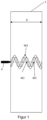
- figure 1 shows the cross section of a flat, unstructured protective plate 1 according to the prior art, in which the propagation of the waves when a projectile P strikes is shown as a schematic representation.
- the elastic waves W1 introduced into the material by the load are reflected at the back and travel back as reflected waves W2 in the metal sheet.
- the material thickness b is typically selected (increased) in such a way that no failure occurs despite the locally occurring excessive loads due to interference.
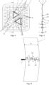
- the protective plate 1 has a spatial structure 2 made up of a regular arrangement of elevations 3 . Between these elevations 3 adjoining depressions 4 are arranged, with the protective plate being deformed over the entire sheet thickness in the area of its structuring.
- the center points M of the elevations 3 form an equilateral triangle with an edge length a on one level, which represents the smallest repeating structural component.
- the centers M1 of the depressions 4 form an equilateral triangle with an edge length a1, which represents the smallest repeating structural component.
- the elevations 3 preferably have a radius R1 of about 20 mm to 250 mm and are rounded from the direction of a first side 5 of the protective plate 1 with a radius R1 and on the second side 6 facing away therefrom with a smaller radius R2.
- the Radius R1 merges tangentially into radius R2 and radius R2 merges tangentially into radius R1.
- the first side 5 is preferably the outward-facing side of the protective plate 1
- the second side 6 is the inward-facing side in the direction of the vehicle interior.
- the increases 3 have the largest radius, the radius R1 to the outside.
- the arrangement is such that the depth t of the elevations corresponds to 0.5 to 1.5 times the panel thickness b1. According to figure 3 the depth corresponds approximately to the plate thickness b1 of protective plate 1.
- This geometry can be created by hot forging in a chilled tool or by cold forging. In any case, production always takes place with an upper and lower tool with a defined active surface.
- the advantage of this arrangement of the elevations 3 is also a comparatively very small thinning of the material of the protective plate 1, with thinning values of less than 10% typically being able to be achieved.
- figure 4 shows a reflection of the waves generated by a projectile in a structured protective plate 1 according to the solution according to the invention. From this it can be seen that a resulting wave W3 arises from the introduced wave W1 and the reflected wave W2, which is greatly reduced.
- the curved spherical segment-like geometry thus causes the elastic waves in the material to be reflected at an angle that deviates from 90°, which means that there can be little or no interference.
- the interference of the two waves can be prevented or reduced, it is possible to use significantly small plate thicknesses P1 for the protective plate 1 according to the invention, which withstand the load without interference.
- the plate thickness b1 of the protective plate 1 according to the invention with structuring 2 can therefore be significantly reduced in comparison to a plate thickness b in the prior art.
- the structuring 2 offers locally increased resistance moments against bending, which has a positive effect on the component rigidity. This locally increased rigidity also makes an important contribution to the improved performance of the structured panels under various impact loads.
- Inkas 7.3 ballistic steel for press hardening - in-house development IndiKar with tensile strength of 2100 MPa
- the protective plates are arranged in a known manner under an essentially conventional vehicle outer skin in the direction of the vehicle interior and thus offer the people in the vehicle reliable protection against fire up to fire class 10 according to VPAM PM 2007, Version 2.
- the protective plates are used, for example, in special protection vehicles such as armored cars, military vehicles and personal protection equipment.
Landscapes
- Engineering & Computer Science (AREA)
- General Engineering & Computer Science (AREA)
- Aiming, Guidance, Guns With A Light Source, Armor, Camouflage, And Targets (AREA)
Description
- Die Erfindung betrifft eine Schutzplatte nach dem Oberbegriff des ersten Patentanspruchs.
- Derartige Schutzplatten kommen z.B. als ballistischer Schutz beispielsweise bei Sonderschutzfahrzeugen wie gepanzerten PKWs, militärischen Fahrzeugen und Personenschutzausrüstungen zum Einsatz.
- Für herkömmliche Karosseriebauteile, besonders mit hohen Anforderungen an den Fußgängerschutz, werden Verfahren zur Erzeugung einer regelmäßigen
- Wölbungsstruktur mittels Walzen, Prägen oder Innenhochdruckumformung eingesetzt. Solche Bauteile werden hauptsächlich im Frontbereich von Personenkraftwagen (z. B. Motorhaube) zu Unterstützung der glatten Außenstruktur eingesetzt. Diese sollen die Biegesteifigkeit des Bauteils durch die räumliche Struktur verbessern und zu einer definierten Verformung im Falle eines Unfalls beitragen.
- Angewendet werden diese Verfahren ausschließlich der Fertigung von Dünnblechteilen mit geringen Festigkeiten.
DE 199 28 370 A1 offenbart eine Schutzplatte gemäß das Oberbegriff des Anspruchs 1. - Aus der Druckschrift
DE 103 39 069 A1 ist ein pressgehärtetes Bauteil mit einer Wölbstruktur bekannt, welches insbesondere ein Strukturbauteil einer Fahrzeugkarosserie ist, welches lokal eine erhöhte Steifigkeit aufweisen soll. Um eine hohe Bauteilfestigkeit zu erreichen, wird das Bauteil aus einem höherfesten Stahl gefertigt. Zur Ausformung der dreidimensionalen Bauteilform kommt ein Warmumformverfahren zum Einsatz, im Zuge dessen das Bauteil gehärtet wird. Während dieses Warmumformverfahrens wird eine lokale steifigkeitserhöhende Verformungsstruktur in das Bauteil eingeformt, die aus einem periodischen Gitter aneinandergrenzender Zellen besteht. Vorzugsweise besteht die Verformungsstruktur bei dieser Lösung aus einem periodischen Muster flacher hexagonaler Beulen, welche in ihren Randbereichen, in denen sie an benachbarte Beulen angrenzen, mit Verrundungen versehen sind. Das Bauteil weist zumindest lokal Zugfestigkeitswerte von > 900 MPa, vorzugsweise > 1200 MPa auf. Über die Dimensionierung der Verformungsstruktur und die Größe der Verrundungen wird keine Aussage getroffen. - Dieses Bauteil wird offensichtlich ebenfalls aus einem Dünnblech gefertigt und ist nicht für beschusssichere Fahrzeuge vorgesehen.
- Für beschusssichere Fahrzeuge kommen als Schutzplatten hinter den Karosseriebauteilen meist im Wesentlichen ebene unstrukturierte Platten aus Panzerstahl mit einer großen Blechdicke zum Einsatz, die jedoch ein sehr hohes Gewicht aufweisen. Bei derartigen ebenen, unstrukturierten Platten werden die, durch die Belastung in das Material eingeleiteten elastischen Wellen an der Rückseite reflektiert und laufen im Blech zurück. Dabei kommt es verstärkt zu konstruktiven Interferenzen der hin- und zurücklaufenden Wellen, die in einer überhöhten lokalen Werkstoffbelastung und letztlich im Materialversagen resultieren (siehe
Figur 1 nach dem Stand der Technik). Um dennoch einen Durchschuss zu verhindern, wird typischerweise die Materialstärke so gewählt (erhöht), dass trotz der lokal auftretenden Belastungsüberhöhungen durch Interferenzen kein Versagen auftritt. - Die Aufgabe der Erfindung ist es, eine Schutzplatte aus metallischen Blechwerkstoffen insbesondere für Sonderschutzfahrzeuge, insbesondere für gepanzerte PKWs, so zu gestalten, dass bei auftretenden hochdynamischen bzw. schlagartigen Belastungen durch Beschuss, Explosion (Blast) oder Unfallszenarien (Crash) keine oder nur geringfügige Interferenzen der elastischen Wellen auftreten und damit ein Bauteilversagen verhindert werden kann, wobei sich diese strukturierten Schutzplatten mit einer im Vergleich zu unstrukturierten Platten homogeneren Materialstruktur und reproduzierbar, verzugsarm fertigen lassen sollen und im Vergleich zu ebenen, unstrukturierten Schutzplatten durch die erhöhte ballistische Halteleistung ein geringeres Gewicht durch geringere Materialstärken aufweisen.
- Diese Aufgabe wird durch die kennzeichnenden Merkmale des ersten Patentanspruchs gelöst.
- Vorteilhafte Ausgestaltungen ergeben sich aus den Unteransprüchen.
- Die Schutzplatte für Sonderschutzfahrzeuge besteht aus durchschusshemmendem Stahl und weist erfindungsgemäß eine räumliche Strukturierung auf, welche bei einer Impactbelastung im Material der Schutzplatte verlaufende eingeleitete Wellen in einem Winkel, der von 90° abweicht, innerhalb des Materials der Schutzplatte reflektiert.
- Aus der eingeleiteten Welle und der reflektierten Welle entsteht eine resultierende Welle, die sich stark abbaut.
- Dadurch wird die Durchschlagkraft des Projektils erheblich reduziert.
- Die Schutzplatte besteht dabei aus durchschusshemmendem Stahl und weist eine räumliche Strukturierung auf, wobei die Strukturierung aus einer sich in X- und Y-Richtung erstreckenden regelmäßigen Anordnung von Erhöhungen auf einer Vorderseite der Schutzplatte und zwischen diesen angeordneten und an diese angrenzenden Vertiefungen besteht und wobei die Schutzplatte im Bereich ihrer Strukturierung über die gesamte Blechdicke umgeformt ist.
- Die Erhöhungen sind bevorzugt kugelsegmentartig ausgebildet und weisen einen ersten Radius auf. Die Vertiefungen sind bevorzugt ebenfalls kugelsegmentartig ausgebildet und weisen einen zweiten Radius auf.
- Der erste Radius beträgt das 6- bis 20-fache, insbesondere das 10- bis 20-fache der Blechdicke. Der zweite Radius beträgt vorteilhafter Weise den 2- bis 8-fachen Wert der Blechdicke, insbesondere den 3- bis 8-fachen Wert.
- In einer vorteilhaften Ausgestaltung hat der erste Radius eine 3- bis 5-mal größeren Wert des zweiten Radius.
- Besonders bevorzugt gehen der erste Radius und der zweite Radius tangential ineinander über.
- Die Tiefe der Erhöhungen entspricht bevorzugt 0,5 bis 1,5-mal der Blechdicke der Schutzplatte. Des Weiteren oder alternativ kann die Tiefe der Vertiefungen ebenfalls 0,5 bis 1,5-mal der Blechdicke der Schutzplatte entsprechen.
- Jede Erhöhung der Strukturierung weist einen Mittelpunkt auf, wobei die Mittelpunkte dreier aneinander angrenzender Erhöhungen auf einer Ebene ein gleichseitiges Dreieck mit einer Kantenlänge bilden und dieses Dreieck einen kleinsten sich wiederholenden Strukturbaustein bildet.
- Besonders bevorzugt weist jede Vertiefung der Strukturierung einen Mittelpunkt auf, wobei die Mittelpunkte dreier aneinander angrenzender Vertiefungen auf einer Ebene ebenfalls ein gleichseitiges Dreieck mit einer weiteren Kantenlänge bilden, wobei dieses gebildete Dreieck einen kleinsten sich wiederholenden Strukturbaustein bildet.
- Die Schutzplatte besteht insbesondere aus einem Dickblech und weist eine Plattenstärke bzw. Blechdicke ab 2 mm und darüber auf.
- Zur Gewährleistung der durchschusshemmenden Eigenschaften der Schutzplatte besteht diese insbesondere aus ballistischem Stahl oder einem Vergütungsstahl.
- Die Strukturierung der Schutzplatte wird durch Warmumformung in einem gekühlten Werkzeug (Presshärten) oder durch Kaltumformung erzeugt.
- Die Erfindung gewährleistet eine mögliche Gewichtseinsparung bei umformend hergestellte Dickblech-Schutzplatten über 2,0mm Blechstärkemit einer räumlichen Struktur für Beschuss und Explosionsbelastungen.
- Es hat sich bei Versuchen gezeigt, dass insbesondere durch Presshärten hergestellte Schutzplatten mit der "Kugelabschnittsstruktur" eine wesentlich höhere Beschusssicherheit aufweisen als ebene Schutzplatten aus dem gleichen Werkstoff und mit gleicher Blechdicke.
- Dies ermöglichte eine Blechdickenreduzierung um ca. 1 bis 3 mm (z.B. von 9.5 mm auf 7,4 mm bei den getesteten Schutzplatten), wodurch eine erhebliche Gewichtseinsparung realisierbar ist.
- Die dabei eingesetzte Dickbleche weisen eine Blechdicke (Plattenstärke) von über 2,0mm auf.
- Vorzugsweise werden Bleche (Dickbleche) aus beschusssicherem Material in Form von ballistischem Stahl wie z.B. Vergütungsstahl oder aus Stahl mit guten ballistischen Eigenschaften wie z.B. Hartmanganstahl eingesetzt.
- Die Erfindung wird nachfolgend an einem Ausführungsbeispiel und zugehörigen Zeichnungen näher erläutert. Es zeigen:
- Figur 1
- Reflektion der durch ein Projektil erzeugten Wellen in einer ebenen unstrukturierten Schutzplatte nach dem Stand der Technik,
- Figur 2
- erfindungsgemäße Schutzplatte in der Draufsicht,
- Figur 3
- Schnitt A-A gemäß
Figur 2 , - Figur 4
- Reflektion der durch ein Projektil erzeugten Wellen in einer strukturierten Schutzplatte nach der erfindungsgemäßen Lösung.
-
Figur 1 zeigt den Querschnitt einer ebenen, unstrukturierten Schutzplatte 1 nach dem Stand der Technik, in welche als Prinzipdarstellung die Ausbreitung der Wellen bei Auftreffen eines Projektils P dargestellt ist. - Bei Auftreffen des Projektils P werden die durch die Belastung in das Material eingeleiteten elastischen Wellen W1 an der Rückseite reflektiert und laufen als reflektierte Wellen W2 im Blech zurück. Dabei kommt es verstärkt zu konstruktiven Interferenzen der hin- und zurücklaufenden Wellen W1, W2, die in einer überhöhten lokalen Werkstoffbelastung und letztlich im Materialversagen resultieren, was durch die Welle W3 als resultierende Welle mit konstruktiven Interferenzen dargestellt ist. Um dennoch einen Durchschuss zu verhindern, wird typischerweise die Materialstärke b so gewählt (erhöht), dass trotz der lokal auftretenden Belastungsüberhöhungen durch Interferenzen kein Versagen auftritt.
- In
Figur 2 wird die erfindungsgemäße Lösung in der Draufsicht als Prinzipskizze dargestellt. - Die Schutzplatte 1 weist eine räumliche Strukturierung 2 aus einer regelmäßigen Anordnung von Erhöhungen 3 auf. Zwischen diesen Erhöhungen 3 sind an diese angrenzende Vertiefungen 4 angeordnet, wobei die Schutzplatte im Bereich ihrer Strukturierung über die gesamte Blechdicke umgeformt ist.
- Die Mittelpunkte M der Erhöhungen 3 bilden auf einer Ebene ein gleichseitiges Dreieck mit einer Kantenlänge a, das den kleinsten sich wiederholenden Strukturbaustein darstellt. Die Mittelpunkte M1 der Vertiefungen 4 bilden auf einer weiteren Ebene ein gleichseitiges Dreieck mit einer Kantenlänge a1, das den kleinsten sich wiederholenden Strukturbaustein darstellt.
- Die Erhöhungen 3 weisen vorzugsweise einen Radius R1 von ca. 20mm bis 250mm auf und sind aus Richtung einer ersten Seite 5 der Schutzplatte 1 mit einem Radius R1 und an der davon abgewandten zweiten Seite 6 mit einem kleineren Radius R2 verrundet. Der Radius R1 geht tangential in den Radius R2 und der Radius R2 wieder tangential in den Radius R1 über. Die erste Seite 5 ist bevorzugt die nach außen weisende Seite der Schutzplatte 1, die zweite Seite 6 die nach innen in Richtung des Fahrzeuginnenraums weisende Seite. Die Erhöhungen 3 weisen den größten Radius, den Radius R1 nach außen auf. Die Vertiefungen 4, welche durch den Radius R2 gebildet werden, bilden auf der zweiten Seite 6 kleinere Erhebungen.
- Die Anordnung erfolgt so, dass die Tiefe t der Erhöhungen 0,5 bis 1,5-mal der Plattenstärke b1 entspricht. Gemäß
Figur 3 entspricht die Tiefe in etwa der Plattenstärke b1 der Schutzplatte 1. - Diese Geometrie kann durch Warmumformung in einem gekühlten Werkzeug oder durch Kaltumformung erzeugt werden. In jedem Fall erfolgt die Herstellung immer mit einem Ober- und Unterwerkzeug mit definierter Wirkfläche.
- Mit diesen umformend hergestellten Dickblech-Schutzplatten mit einer räumlichen Struktur sind bei dem Einsatz als beschusssichere Schutzplatten für Beschuss und Explosionsbelastungen deutlich geringere Materialdicken möglich, was durch zahlreiche Beschussversuche bestätigt werden konnte.
- Vorteil dieser Anordnung der Erhöhungen 3 ist ebenfalls eine vergleichsweise sehr geringe Ausdünnung des Materials der Schutzplatte 1, wobei typischerweise Ausdünnungswerte von kleiner 10 % erreicht werden können.
- In
Figur 4 ist eine Reflektion der durch ein Projektil erzeugten Wellen in einer strukturierten Schutzplatte 1 nach der erfindungsgemäßen Lösung dargestellt. Daraus ist ersichtlich, dass aus der eingeleiteten Welle W1 und der reflektierten Welle W2 eine resultierende Welle W3 entsteht, welche sich stark abbaut. - Die gekrümmte kugelsegmentartige Geometrie führt somit dazu, dass die elastischen Wellen im Material unter einem Winkel zurückgeworfen werden, der von 90 ° abweicht, wodurch es zu keinen bzw. nur geringen Interferenzen kommen kann.
- Wenn demnach die Interferenz der beiden Wellen verhindert bzw. reduziert werden können, ist es möglich, deutlich geringe Plattenstärken P1 für die erfindungsgemäße Schutzplatte 1 einzusetzen, die der Belastung ohne Interferenzen standhalten.
- Die Plattenstärke b1 der erfindungsgemäßen Schutzplatte 1 mit Strukturierung 2 kann daher im Vergleich zu einer Plattenstärke b beim Stand der Technik deutlich reduziert werden.
- Darüber hinaus bietet die Strukturierung 2 lokal abhängig erhöhte Widerstandmomente gegen Biegung, was sich positiv auf die Bauteilsteifigkeit auswirkt. Diese lokal erhöhte Steifigkeit leistet zusätzlich einen wichtigen Beitrag zur verbesserten Performance der strukturierten Platten bei verschiedenen Impactbelastungen.
- Mit der erfindungsgemäßen Lösung können geringere Wandstärken für bestimmte Belastungsfälle eingesetzt werden, was zu einer signifikanten Gewichtsreduzierung führt. Beispiel: für 7,62x51 FMJ/PB/HC, P80 CBC mit 820 m/s von 10m Entfernung am Werkstoff Inkas 7.3 (Ballistischer Stahl zum Presshärten - Eigenentwicklung IndiKar mit Zugfestigkeiten von 2100MPa) Reduzierung von 9,2mm auf 8,0mm Blechstärke um 13%.
- Die Schutzplatten werden bekannter Weise unter einer im Wesentlichen herkömmlichen Fahrzeugaußenhaut in Richtung zum Fahrzeuginnenraum angeordnet und bieten damit den sich im Fahrzeug befindlichen Personen einen zuverlässigen Schutz bei Beschuss bis zu Beschussklasse 10 nach VPAM PM 2007, Fassung 2.
- Die Schutzplatten kommen beispielsweise bei Sonderschutzfahrzeugen wie gepanzerten PKWs, militärischen Fahrzeugen und Personenschutzausrüstungen zum Einsatz.
-
- 1
- Schutzplatte
- 2
- Strukturierung
- 3
- Erhöhung
- 4
- Vertiefung
- 5
- erste Seite
- 6
- zweite Seite
- a
- Kantenlänge
- a1
- Kantenlänge
- b
- Plattenstärke Stand der Technik
- b1
- Plattenstärke
- t
- Ziehtiefe
- M
- Mittelpunkt Erhöhung
- M1
- Mittelpunkt Vertiefung
- P
- Projektil
- R
- Radius eines Kugelsegments
- R1
- erster Radius
- R2
- zweiter Radius
- T
- gleichseitiges Dreieck
- T1
- gleichseitiges Dreieck
- W1
- eingeleitete Wellen
- W2
- reflektierte Wellen
- W3
- resultierende Wellen
Claims (9)
- Schutzplatte, insbesondere für Sonderschutzfahrzeuge, wobei die Schutzplatte (1) aus durchschusshemmendem Stahl besteht, und eine räumliche Strukturierung (2) aufweist, wobei die Strukturierung (2) aus einer sich in X- und Y-Richtung erstreckenden regelmäßigen Anordnung von Erhöhungen (3) auf einer Vorderseite der Schutzplatte (1) und zwischen diesen angeordneten und an diese angrenzenden Vertiefungen (4) besteht und wobei die Schutzplatte (1) im Bereich ihrer Strukturierung (2) über die gesamte Blechdicke (b1) umgeformt ist, dadurch gekennzeichnet, dass die Erhöhungen (3) kugelsegmentartig ausgebildet sind und einen ersten Radius (R1) aufweisen und dass die Vertiefungen (4) kugelsegmentartig ausgebildet sind und einen zweiten Radius (R2) aufweisen, wobei der erste Radius (R1) und der zweite Radius (R2) tangential ineinander übergehen und die nach außen weisenden Erhöhungen 3 den größeren Radius R1 bilden und die Vertiefungen (4) welche durch den Radius R2 gebildet werden, auf der zum Fahrzeuginnenraum weisenden zweiten Seite 6 mit einem kleineren Radius verrundet sind und wobei die Tiefe (t) der Erhöhungen (3) und/oder der Vertiefungen 0,5 bis 1,5-mal der Blechdicke (b1) der Schutzplatte (1) entspricht.
- Schutzplatte nach Anspruch 1, dadurch gekennzeichnet, dass der erste Radius (R1) das 6- bis 20-fache der Blechdicke (b1) beträgt.
- Schutzplatte nach Anspruch 1, dadurch gekennzeichnet, dass der zweite Radius (R2) das 2- bis 8-fache der Blechdicke (b1) beträgt.
- Schutzplatte nach Anspruch 1, dadurch gekennzeichnet, dass der erste Radius (R1) das Dreifache bis Fünffache des zweiten Radius (R2) beträgt.
- Schutzplatte nach einem der Ansprüche 1 bis 4, dadurch gekennzeichnet, dass jede Erhöhung (3) der Strukturierung (2) einen Mittelpunkt (M) aufweist, wobei die Mittelpunkte (M) dreier aneinander angrenzender Erhöhungen (3) auf einer Ebene ein gleichseitiges Dreieck (T) mit einer Kantenlänge (a) bilden, wobei das Dreieck (T) einen kleinsten sich wiederholenden Strukturbaustein bildet.
- Schutzplatte nach einem der Ansprüche 1 bis 5, dadurch gekennzeichnet, dass jede Vertiefung (4) der Strukturierung (2) einen Mittelpunkt (M1) aufweist, wobei die Mittelpunkte (M1) dreier aneinander angrenzender Vertiefungen (4) auf einer Ebene ein gleichseitiges Dreieck (T1) mit einer Kantenlänge (a1) bilden, wobei das Dreieck (T1) einen kleinsten sich wiederholenden Strukturbaustein bildet.
- Schutzplatte nach einem der Ansprüche 1 bis 6, dadurch gekennzeichnet, dass die Schutzplatte (1) aus einem Dickblech besteht und eine Plattenstärke (b1) ab 2mm und darüber aufweist.
- Schutzplatte nach einem der Ansprüche 1 bis 7, dadurch gekennzeichnet, dass die Schutzplatte (1) aus ballistischem Stahl oder Vergütungsstahl besteht.
- Schutzplatte nach einem der Ansprüche 1 bis 8, dadurch gekennzeichnet, dass die Strukturierung (2) durch Warmumformung in einem gekühlten Werkzeug (Presshärten) oder durch Kaltumformung erzeugt ist.
Applications Claiming Priority (2)
| Application Number | Priority Date | Filing Date | Title |
|---|---|---|---|
| DE102020128667.8A DE102020128667A1 (de) | 2020-10-30 | 2020-10-30 | Schutzplatte |
| DE202021105906.0U DE202021105906U1 (de) | 2020-10-30 | 2021-10-28 | Schutzplatte |
Publications (2)
| Publication Number | Publication Date |
|---|---|
| EP3992569A1 EP3992569A1 (de) | 2022-05-04 |
| EP3992569B1 true EP3992569B1 (de) | 2023-06-21 |
Family
ID=80267074
Family Applications (1)
| Application Number | Title | Priority Date | Filing Date |
|---|---|---|---|
| EP21205440.7A Active EP3992569B1 (de) | 2020-10-30 | 2021-10-29 | Schutzplatte |
Country Status (2)
| Country | Link |
|---|---|
| EP (1) | EP3992569B1 (de) |
| DE (2) | DE102020128667A1 (de) |
Family Cites Families (12)
| Publication number | Priority date | Publication date | Assignee | Title |
|---|---|---|---|---|
| NL101756C (nl) * | 1952-10-07 | 1962-07-16 | Pfistershammer Josef | Constructie-element uit plaatvormig materiaal,voorzien van uitstulpingen |
| US4704943A (en) | 1981-06-15 | 1987-11-10 | Mcdougal John A | Impact structures |
| DE19928370A1 (de) * | 1999-06-21 | 2001-01-04 | Sachsenring Entwicklungsgmbh | Energieabsorbierendes Panzerungselement |
| DE10006348C2 (de) * | 2000-02-12 | 2001-12-06 | Daimler Chrysler Ag | Bauteil mit lokal begrenzten Versteifungsbereichen und Verfahren zu seiner Herstellung |
| DE10339069A1 (de) | 2003-08-26 | 2005-03-24 | Daimlerchrysler Ag | Pressgehärtetes Bauteil mit einer Wölbstruktur |
| DE102007002210B4 (de) * | 2007-01-16 | 2013-07-04 | Audi Ag | Platte für eine schussfeste Panzerung |
| US20090136702A1 (en) | 2007-11-15 | 2009-05-28 | Yabei Gu | Laminated armor having a non-planar interface design to mitigate stress and shock waves |
| JP5520963B2 (ja) * | 2009-11-13 | 2014-06-11 | 株式会社Uacj | 凹凸部を有する板材並びにこれを用いた積層構造体及び車両パネル |
| CN102939511B (zh) | 2010-05-21 | 2015-01-21 | 斯凯达克斯科技有限公司 | 超压保护 |
| US9726249B2 (en) | 2011-05-13 | 2017-08-08 | Mississippi State University | Shock mitigating materials and methods utilizing spiral shaped elements |
| US10288386B1 (en) * | 2016-10-12 | 2019-05-14 | Brian Moore | Body armor and body armor manufacturing methods |
| DE102019127992B4 (de) | 2019-10-16 | 2022-03-17 | Indikar Individual Karosseriebau Gmbh | Schutzplatte |
-
2020
- 2020-10-30 DE DE102020128667.8A patent/DE102020128667A1/de not_active Ceased
-
2021
- 2021-10-28 DE DE202021105906.0U patent/DE202021105906U1/de active Active
- 2021-10-29 EP EP21205440.7A patent/EP3992569B1/de active Active
Also Published As
| Publication number | Publication date |
|---|---|
| DE202021105906U1 (de) | 2022-02-01 |
| DE102020128667A1 (de) | 2022-05-05 |
| EP3992569A1 (de) | 2022-05-04 |
Similar Documents
| Publication | Publication Date | Title |
|---|---|---|
| EP0897097B1 (de) | Sandwichplatte zum Schutz gegen explosive Minen | |
| EP1949017B1 (de) | Verbundpanzerungselement und wirkkörperelement zur einbringung in ein verbundpanzerungselement | |
| DE102014009337B4 (de) | Stoßfängersystem für ein Fahrzeug | |
| EP2807445B1 (de) | Verfahren zur herstellung des fahrzeugbodens eines minengeschützten fahrzeuges | |
| DE102009053349B4 (de) | Panzerstahlbauteil | |
| DE202020105963U1 (de) | Kraftfahrzeugbauteil | |
| DE102019127992B4 (de) | Schutzplatte | |
| EP2072945B1 (de) | Verbundpanzerplatte | |
| DE19740103A1 (de) | Bodenschutzvorrichtung für Fahrzeuge gegen Minen | |
| EP2806245B1 (de) | Anordnung zum Schutz eines Objekts gegen anfliegende Projektile | |
| EP1152207B1 (de) | Panzerung, insbesondere für Sicherheitskraftfahrzeuge | |
| DE19928370A1 (de) | Energieabsorbierendes Panzerungselement | |
| EP3992569A1 (de) | Schutzplatte | |
| EP1464915B1 (de) | Minenschutzanordnung | |
| EP2053340B1 (de) | Flächiges Verbundpanzerungselement | |
| EP3055639B1 (de) | Schutzelement mit entkopplungsschicht | |
| DE4300746C2 (de) | Leichtpanzerung | |
| DE102011109660B3 (de) | Formbauteil zu Panzerungszwecken und dessen Herstellungsverfahren | |
| DE10318492B4 (de) | Vorrichtung zum Schutz eines Objekts | |
| DE102012106950A1 (de) | Panzerung für Fahrzeuge und Verwendung einer Panzerung | |
| DE102017102547B4 (de) | Verfahren zur Herstellung eines Schutzelementes zur Panzerung eines Kraftfahrzeugs sowie mit dem Verfahren hergestelltes Schutzelement und Kraftfahrzeug mit wenigstens einem solchen Schutzelement | |
| DE1120939B (de) | Geschichtete Panzerplatte | |
| DE102008012720A1 (de) | Panzerung für ein Fahrzeug | |
| EP2053339B1 (de) | Flächiges Verbundpanzerungselement | |
| EP4474754B1 (de) | Verfahren zur herstellung eines aus mehreren einzelprofilen gebildeten schutzelementes zur panzerung eines kraftfahrzeuges sowie mit dem verfahren hergestelltes schutzelement |
Legal Events
| Date | Code | Title | Description |
|---|---|---|---|
| PUAI | Public reference made under article 153(3) epc to a published international application that has entered the european phase |
Free format text: ORIGINAL CODE: 0009012 |
|
| STAA | Information on the status of an ep patent application or granted ep patent |
Free format text: STATUS: THE APPLICATION HAS BEEN PUBLISHED |
|
| AK | Designated contracting states |
Kind code of ref document: A1 Designated state(s): AL AT BE BG CH CY CZ DE DK EE ES FI FR GB GR HR HU IE IS IT LI LT LU LV MC MK MT NL NO PL PT RO RS SE SI SK SM TR |
|
| STAA | Information on the status of an ep patent application or granted ep patent |
Free format text: STATUS: REQUEST FOR EXAMINATION WAS MADE |
|
| 17P | Request for examination filed |
Effective date: 20220610 |
|
| RBV | Designated contracting states (corrected) |
Designated state(s): AL AT BE BG CH CY CZ DE DK EE ES FI FR GB GR HR HU IE IS IT LI LT LU LV MC MK MT NL NO PL PT RO RS SE SI SK SM TR |
|
| GRAP | Despatch of communication of intention to grant a patent |
Free format text: ORIGINAL CODE: EPIDOSNIGR1 |
|
| STAA | Information on the status of an ep patent application or granted ep patent |
Free format text: STATUS: GRANT OF PATENT IS INTENDED |
|
| INTG | Intention to grant announced |
Effective date: 20230324 |
|
| GRAS | Grant fee paid |
Free format text: ORIGINAL CODE: EPIDOSNIGR3 |
|
| GRAA | (expected) grant |
Free format text: ORIGINAL CODE: 0009210 |
|
| STAA | Information on the status of an ep patent application or granted ep patent |
Free format text: STATUS: THE PATENT HAS BEEN GRANTED |
|
| AK | Designated contracting states |
Kind code of ref document: B1 Designated state(s): AL AT BE BG CH CY CZ DE DK EE ES FI FR GB GR HR HU IE IS IT LI LT LU LV MC MK MT NL NO PL PT RO RS SE SI SK SM TR |
|
| REG | Reference to a national code |
Ref country code: CH Ref legal event code: EP |
|
| REG | Reference to a national code |
Ref country code: DE Ref legal event code: R096 Ref document number: 502021000900 Country of ref document: DE |
|
| REG | Reference to a national code |
Ref country code: AT Ref legal event code: REF Ref document number: 1581170 Country of ref document: AT Kind code of ref document: T Effective date: 20230715 |
|
| REG | Reference to a national code |
Ref country code: IE Ref legal event code: FG4D Free format text: LANGUAGE OF EP DOCUMENT: GERMAN |
|
| REG | Reference to a national code |
Ref country code: LT Ref legal event code: MG9D |
|
| REG | Reference to a national code |
Ref country code: NL Ref legal event code: MP Effective date: 20230621 |
|
| PG25 | Lapsed in a contracting state [announced via postgrant information from national office to epo] |
Ref country code: SE Free format text: LAPSE BECAUSE OF FAILURE TO SUBMIT A TRANSLATION OF THE DESCRIPTION OR TO PAY THE FEE WITHIN THE PRESCRIBED TIME-LIMIT Effective date: 20230621 Ref country code: NO Free format text: LAPSE BECAUSE OF FAILURE TO SUBMIT A TRANSLATION OF THE DESCRIPTION OR TO PAY THE FEE WITHIN THE PRESCRIBED TIME-LIMIT Effective date: 20230921 |
|
| PG25 | Lapsed in a contracting state [announced via postgrant information from national office to epo] |
Ref country code: RS Free format text: LAPSE BECAUSE OF FAILURE TO SUBMIT A TRANSLATION OF THE DESCRIPTION OR TO PAY THE FEE WITHIN THE PRESCRIBED TIME-LIMIT Effective date: 20230621 Ref country code: NL Free format text: LAPSE BECAUSE OF FAILURE TO SUBMIT A TRANSLATION OF THE DESCRIPTION OR TO PAY THE FEE WITHIN THE PRESCRIBED TIME-LIMIT Effective date: 20230621 Ref country code: LV Free format text: LAPSE BECAUSE OF FAILURE TO SUBMIT A TRANSLATION OF THE DESCRIPTION OR TO PAY THE FEE WITHIN THE PRESCRIBED TIME-LIMIT Effective date: 20230621 Ref country code: LT Free format text: LAPSE BECAUSE OF FAILURE TO SUBMIT A TRANSLATION OF THE DESCRIPTION OR TO PAY THE FEE WITHIN THE PRESCRIBED TIME-LIMIT Effective date: 20230621 Ref country code: HR Free format text: LAPSE BECAUSE OF FAILURE TO SUBMIT A TRANSLATION OF THE DESCRIPTION OR TO PAY THE FEE WITHIN THE PRESCRIBED TIME-LIMIT Effective date: 20230621 Ref country code: GR Free format text: LAPSE BECAUSE OF FAILURE TO SUBMIT A TRANSLATION OF THE DESCRIPTION OR TO PAY THE FEE WITHIN THE PRESCRIBED TIME-LIMIT Effective date: 20230922 |
|
| PG25 | Lapsed in a contracting state [announced via postgrant information from national office to epo] |
Ref country code: FI Free format text: LAPSE BECAUSE OF FAILURE TO SUBMIT A TRANSLATION OF THE DESCRIPTION OR TO PAY THE FEE WITHIN THE PRESCRIBED TIME-LIMIT Effective date: 20230621 |
|
| PG25 | Lapsed in a contracting state [announced via postgrant information from national office to epo] |
Ref country code: SK Free format text: LAPSE BECAUSE OF FAILURE TO SUBMIT A TRANSLATION OF THE DESCRIPTION OR TO PAY THE FEE WITHIN THE PRESCRIBED TIME-LIMIT Effective date: 20230621 |
|
| PG25 | Lapsed in a contracting state [announced via postgrant information from national office to epo] |
Ref country code: ES Free format text: LAPSE BECAUSE OF FAILURE TO SUBMIT A TRANSLATION OF THE DESCRIPTION OR TO PAY THE FEE WITHIN THE PRESCRIBED TIME-LIMIT Effective date: 20230621 |
|
| PG25 | Lapsed in a contracting state [announced via postgrant information from national office to epo] |
Ref country code: IS Free format text: LAPSE BECAUSE OF FAILURE TO SUBMIT A TRANSLATION OF THE DESCRIPTION OR TO PAY THE FEE WITHIN THE PRESCRIBED TIME-LIMIT Effective date: 20231021 |
|
| PG25 | Lapsed in a contracting state [announced via postgrant information from national office to epo] |
Ref country code: SM Free format text: LAPSE BECAUSE OF FAILURE TO SUBMIT A TRANSLATION OF THE DESCRIPTION OR TO PAY THE FEE WITHIN THE PRESCRIBED TIME-LIMIT Effective date: 20230621 Ref country code: SK Free format text: LAPSE BECAUSE OF FAILURE TO SUBMIT A TRANSLATION OF THE DESCRIPTION OR TO PAY THE FEE WITHIN THE PRESCRIBED TIME-LIMIT Effective date: 20230621 Ref country code: RO Free format text: LAPSE BECAUSE OF FAILURE TO SUBMIT A TRANSLATION OF THE DESCRIPTION OR TO PAY THE FEE WITHIN THE PRESCRIBED TIME-LIMIT Effective date: 20230621 Ref country code: PT Free format text: LAPSE BECAUSE OF FAILURE TO SUBMIT A TRANSLATION OF THE DESCRIPTION OR TO PAY THE FEE WITHIN THE PRESCRIBED TIME-LIMIT Effective date: 20231023 Ref country code: IS Free format text: LAPSE BECAUSE OF FAILURE TO SUBMIT A TRANSLATION OF THE DESCRIPTION OR TO PAY THE FEE WITHIN THE PRESCRIBED TIME-LIMIT Effective date: 20231021 Ref country code: ES Free format text: LAPSE BECAUSE OF FAILURE TO SUBMIT A TRANSLATION OF THE DESCRIPTION OR TO PAY THE FEE WITHIN THE PRESCRIBED TIME-LIMIT Effective date: 20230621 Ref country code: EE Free format text: LAPSE BECAUSE OF FAILURE TO SUBMIT A TRANSLATION OF THE DESCRIPTION OR TO PAY THE FEE WITHIN THE PRESCRIBED TIME-LIMIT Effective date: 20230621 Ref country code: CZ Free format text: LAPSE BECAUSE OF FAILURE TO SUBMIT A TRANSLATION OF THE DESCRIPTION OR TO PAY THE FEE WITHIN THE PRESCRIBED TIME-LIMIT Effective date: 20230621 |
|
| PG25 | Lapsed in a contracting state [announced via postgrant information from national office to epo] |
Ref country code: PL Free format text: LAPSE BECAUSE OF FAILURE TO SUBMIT A TRANSLATION OF THE DESCRIPTION OR TO PAY THE FEE WITHIN THE PRESCRIBED TIME-LIMIT Effective date: 20230621 |
|
| REG | Reference to a national code |
Ref country code: DE Ref legal event code: R097 Ref document number: 502021000900 Country of ref document: DE |
|
| PLBE | No opposition filed within time limit |
Free format text: ORIGINAL CODE: 0009261 |
|
| STAA | Information on the status of an ep patent application or granted ep patent |
Free format text: STATUS: NO OPPOSITION FILED WITHIN TIME LIMIT |
|
| PG25 | Lapsed in a contracting state [announced via postgrant information from national office to epo] |
Ref country code: DK Free format text: LAPSE BECAUSE OF FAILURE TO SUBMIT A TRANSLATION OF THE DESCRIPTION OR TO PAY THE FEE WITHIN THE PRESCRIBED TIME-LIMIT Effective date: 20230621 |
|
| PG25 | Lapsed in a contracting state [announced via postgrant information from national office to epo] |
Ref country code: SI Free format text: LAPSE BECAUSE OF FAILURE TO SUBMIT A TRANSLATION OF THE DESCRIPTION OR TO PAY THE FEE WITHIN THE PRESCRIBED TIME-LIMIT Effective date: 20230621 |
|
| 26N | No opposition filed |
Effective date: 20240322 |
|
| PG25 | Lapsed in a contracting state [announced via postgrant information from national office to epo] |
Ref country code: SI Free format text: LAPSE BECAUSE OF FAILURE TO SUBMIT A TRANSLATION OF THE DESCRIPTION OR TO PAY THE FEE WITHIN THE PRESCRIBED TIME-LIMIT Effective date: 20230621 Ref country code: IT Free format text: LAPSE BECAUSE OF FAILURE TO SUBMIT A TRANSLATION OF THE DESCRIPTION OR TO PAY THE FEE WITHIN THE PRESCRIBED TIME-LIMIT Effective date: 20230621 Ref country code: MC Free format text: LAPSE BECAUSE OF FAILURE TO SUBMIT A TRANSLATION OF THE DESCRIPTION OR TO PAY THE FEE WITHIN THE PRESCRIBED TIME-LIMIT Effective date: 20230621 |
|
| REG | Reference to a national code |
Ref country code: BE Ref legal event code: MM Effective date: 20231031 |
|
| PG25 | Lapsed in a contracting state [announced via postgrant information from national office to epo] |
Ref country code: LU Free format text: LAPSE BECAUSE OF NON-PAYMENT OF DUE FEES Effective date: 20231029 |
|
| PG25 | Lapsed in a contracting state [announced via postgrant information from national office to epo] |
Ref country code: LU Free format text: LAPSE BECAUSE OF NON-PAYMENT OF DUE FEES Effective date: 20231029 |
|
| PG25 | Lapsed in a contracting state [announced via postgrant information from national office to epo] |
Ref country code: BE Free format text: LAPSE BECAUSE OF NON-PAYMENT OF DUE FEES Effective date: 20231031 |
|
| PG25 | Lapsed in a contracting state [announced via postgrant information from national office to epo] |
Ref country code: IE Free format text: LAPSE BECAUSE OF NON-PAYMENT OF DUE FEES Effective date: 20231029 |
|
| PG25 | Lapsed in a contracting state [announced via postgrant information from national office to epo] |
Ref country code: IE Free format text: LAPSE BECAUSE OF NON-PAYMENT OF DUE FEES Effective date: 20231029 |
|
| PG25 | Lapsed in a contracting state [announced via postgrant information from national office to epo] |
Ref country code: BG Free format text: LAPSE BECAUSE OF FAILURE TO SUBMIT A TRANSLATION OF THE DESCRIPTION OR TO PAY THE FEE WITHIN THE PRESCRIBED TIME-LIMIT Effective date: 20230621 |
|
| PG25 | Lapsed in a contracting state [announced via postgrant information from national office to epo] |
Ref country code: BG Free format text: LAPSE BECAUSE OF FAILURE TO SUBMIT A TRANSLATION OF THE DESCRIPTION OR TO PAY THE FEE WITHIN THE PRESCRIBED TIME-LIMIT Effective date: 20230621 |
|
| PGFP | Annual fee paid to national office [announced via postgrant information from national office to epo] |
Ref country code: FR Payment date: 20241025 Year of fee payment: 4 |
|
| REG | Reference to a national code |
Ref country code: CH Ref legal event code: PL |
|
| PG25 | Lapsed in a contracting state [announced via postgrant information from national office to epo] |
Ref country code: CH Free format text: LAPSE BECAUSE OF NON-PAYMENT OF DUE FEES Effective date: 20241031 |
|
| PG25 | Lapsed in a contracting state [announced via postgrant information from national office to epo] |
Ref country code: CY Free format text: LAPSE BECAUSE OF FAILURE TO SUBMIT A TRANSLATION OF THE DESCRIPTION OR TO PAY THE FEE WITHIN THE PRESCRIBED TIME-LIMIT; INVALID AB INITIO Effective date: 20211029 |
|
| PG25 | Lapsed in a contracting state [announced via postgrant information from national office to epo] |
Ref country code: TR Free format text: LAPSE BECAUSE OF FAILURE TO SUBMIT A TRANSLATION OF THE DESCRIPTION OR TO PAY THE FEE WITHIN THE PRESCRIBED TIME-LIMIT Effective date: 20230621 |
|
| PGFP | Annual fee paid to national office [announced via postgrant information from national office to epo] |
Ref country code: DE Payment date: 20250714 Year of fee payment: 5 |
|
| PGFP | Annual fee paid to national office [announced via postgrant information from national office to epo] |
Ref country code: AT Payment date: 20260113 Year of fee payment: 5 |
|
| PG25 | Lapsed in a contracting state [announced via postgrant information from national office to epo] |
Ref country code: HU Free format text: LAPSE BECAUSE OF FAILURE TO SUBMIT A TRANSLATION OF THE DESCRIPTION OR TO PAY THE FEE WITHIN THE PRESCRIBED TIME-LIMIT; INVALID AB INITIO Effective date: 20211029 |