EP3992445A1 - Verfahren zum betrieb eines zweitaktmotors - Google Patents
Verfahren zum betrieb eines zweitaktmotors Download PDFInfo
- Publication number
- EP3992445A1 EP3992445A1 EP20205168.6A EP20205168A EP3992445A1 EP 3992445 A1 EP3992445 A1 EP 3992445A1 EP 20205168 A EP20205168 A EP 20205168A EP 3992445 A1 EP3992445 A1 EP 3992445A1
- Authority
- EP
- European Patent Office
- Prior art keywords
- fuel valve
- crankshaft
- fuel
- block
- revolutions
- Prior art date
- Legal status (The legal status is an assumption and is not a legal conclusion. Google has not performed a legal analysis and makes no representation as to the accuracy of the status listed.)
- Granted
Links
Images

Classifications
-
- F—MECHANICAL ENGINEERING; LIGHTING; HEATING; WEAPONS; BLASTING
- F02—COMBUSTION ENGINES; HOT-GAS OR COMBUSTION-PRODUCT ENGINE PLANTS
- F02D—CONTROLLING COMBUSTION ENGINES
- F02D41/00—Electrical control of supply of combustible mixture or its constituents
- F02D41/30—Controlling fuel injection
- F02D41/32—Controlling fuel injection of the low pressure type
- F02D41/34—Controlling fuel injection of the low pressure type with means for controlling injection timing or duration
- F02D41/345—Controlling injection timing
-
- F—MECHANICAL ENGINEERING; LIGHTING; HEATING; WEAPONS; BLASTING
- F02—COMBUSTION ENGINES; HOT-GAS OR COMBUSTION-PRODUCT ENGINE PLANTS
- F02D—CONTROLLING COMBUSTION ENGINES
- F02D41/00—Electrical control of supply of combustible mixture or its constituents
- F02D41/30—Controlling fuel injection
-
- F—MECHANICAL ENGINEERING; LIGHTING; HEATING; WEAPONS; BLASTING
- F02—COMBUSTION ENGINES; HOT-GAS OR COMBUSTION-PRODUCT ENGINE PLANTS
- F02B—INTERNAL-COMBUSTION PISTON ENGINES; COMBUSTION ENGINES IN GENERAL
- F02B75/00—Other engines
- F02B75/02—Engines characterised by their cycles, e.g. six-stroke
-
- F—MECHANICAL ENGINEERING; LIGHTING; HEATING; WEAPONS; BLASTING
- F02—COMBUSTION ENGINES; HOT-GAS OR COMBUSTION-PRODUCT ENGINE PLANTS
- F02D—CONTROLLING COMBUSTION ENGINES
- F02D33/00—Controlling delivery of fuel or combustion-air, not otherwise provided for
- F02D33/003—Controlling the feeding of liquid fuel from storage containers to carburettors or fuel-injection apparatus ; Failure or leakage prevention; Diagnosis or detection of failure; Arrangement of sensors in the fuel system; Electric wiring; Electrostatic discharge
-
- F—MECHANICAL ENGINEERING; LIGHTING; HEATING; WEAPONS; BLASTING
- F02—COMBUSTION ENGINES; HOT-GAS OR COMBUSTION-PRODUCT ENGINE PLANTS
- F02D—CONTROLLING COMBUSTION ENGINES
- F02D41/00—Electrical control of supply of combustible mixture or its constituents
- F02D41/20—Output circuits, e.g. for controlling currents in command coils
-
- F—MECHANICAL ENGINEERING; LIGHTING; HEATING; WEAPONS; BLASTING
- F02—COMBUSTION ENGINES; HOT-GAS OR COMBUSTION-PRODUCT ENGINE PLANTS
- F02D—CONTROLLING COMBUSTION ENGINES
- F02D41/00—Electrical control of supply of combustible mixture or its constituents
- F02D41/30—Controlling fuel injection
- F02D41/3005—Details not otherwise provided for
-
- F—MECHANICAL ENGINEERING; LIGHTING; HEATING; WEAPONS; BLASTING
- F02—COMBUSTION ENGINES; HOT-GAS OR COMBUSTION-PRODUCT ENGINE PLANTS
- F02D—CONTROLLING COMBUSTION ENGINES
- F02D41/00—Electrical control of supply of combustible mixture or its constituents
- F02D41/30—Controlling fuel injection
- F02D41/32—Controlling fuel injection of the low pressure type
- F02D41/34—Controlling fuel injection of the low pressure type with means for controlling injection timing or duration
-
- F—MECHANICAL ENGINEERING; LIGHTING; HEATING; WEAPONS; BLASTING
- F02—COMBUSTION ENGINES; HOT-GAS OR COMBUSTION-PRODUCT ENGINE PLANTS
- F02M—SUPPLYING COMBUSTION ENGINES IN GENERAL WITH COMBUSTIBLE MIXTURES OR CONSTITUENTS THEREOF
- F02M37/00—Apparatus or systems for feeding liquid fuel from storage containers to carburettors or fuel-injection apparatus; Arrangements for purifying liquid fuel specially adapted for, or arranged on, internal-combustion engines
- F02M37/0011—Constructional details; Manufacturing or assembly of elements of fuel systems; Materials therefor
- F02M37/0023—Valves in the fuel supply and return system
-
- F—MECHANICAL ENGINEERING; LIGHTING; HEATING; WEAPONS; BLASTING
- F02—COMBUSTION ENGINES; HOT-GAS OR COMBUSTION-PRODUCT ENGINE PLANTS
- F02B—INTERNAL-COMBUSTION PISTON ENGINES; COMBUSTION ENGINES IN GENERAL
- F02B75/00—Other engines
- F02B75/02—Engines characterised by their cycles, e.g. six-stroke
- F02B2075/022—Engines characterised by their cycles, e.g. six-stroke having less than six strokes per cycle
- F02B2075/025—Engines characterised by their cycles, e.g. six-stroke having less than six strokes per cycle two
-
- F—MECHANICAL ENGINEERING; LIGHTING; HEATING; WEAPONS; BLASTING
- F02—COMBUSTION ENGINES; HOT-GAS OR COMBUSTION-PRODUCT ENGINE PLANTS
- F02D—CONTROLLING COMBUSTION ENGINES
- F02D41/00—Electrical control of supply of combustible mixture or its constituents
- F02D41/20—Output circuits, e.g. for controlling currents in command coils
- F02D2041/202—Output circuits, e.g. for controlling currents in command coils characterised by the control of the circuit
- F02D2041/2055—Output circuits, e.g. for controlling currents in command coils characterised by the control of the circuit with means for determining actual opening or closing time
-
- F—MECHANICAL ENGINEERING; LIGHTING; HEATING; WEAPONS; BLASTING
- F02—COMBUSTION ENGINES; HOT-GAS OR COMBUSTION-PRODUCT ENGINE PLANTS
- F02D—CONTROLLING COMBUSTION ENGINES
- F02D2200/00—Input parameters for engine control
- F02D2200/02—Input parameters for engine control the parameters being related to the engine
- F02D2200/021—Engine temperature
-
- F—MECHANICAL ENGINEERING; LIGHTING; HEATING; WEAPONS; BLASTING
- F02—COMBUSTION ENGINES; HOT-GAS OR COMBUSTION-PRODUCT ENGINE PLANTS
- F02D—CONTROLLING COMBUSTION ENGINES
- F02D2200/00—Input parameters for engine control
- F02D2200/02—Input parameters for engine control the parameters being related to the engine
- F02D2200/024—Fluid pressure of lubricating oil or working fluid
-
- F—MECHANICAL ENGINEERING; LIGHTING; HEATING; WEAPONS; BLASTING
- F02—COMBUSTION ENGINES; HOT-GAS OR COMBUSTION-PRODUCT ENGINE PLANTS
- F02D—CONTROLLING COMBUSTION ENGINES
- F02D2200/00—Input parameters for engine control
- F02D2200/02—Input parameters for engine control the parameters being related to the engine
- F02D2200/04—Engine intake system parameters
- F02D2200/0404—Throttle position
-
- F—MECHANICAL ENGINEERING; LIGHTING; HEATING; WEAPONS; BLASTING
- F02—COMBUSTION ENGINES; HOT-GAS OR COMBUSTION-PRODUCT ENGINE PLANTS
- F02D—CONTROLLING COMBUSTION ENGINES
- F02D2200/00—Input parameters for engine control
- F02D2200/02—Input parameters for engine control the parameters being related to the engine
- F02D2200/10—Parameters related to the engine output, e.g. engine torque or engine speed
- F02D2200/101—Engine speed
-
- F—MECHANICAL ENGINEERING; LIGHTING; HEATING; WEAPONS; BLASTING
- F02—COMBUSTION ENGINES; HOT-GAS OR COMBUSTION-PRODUCT ENGINE PLANTS
- F02D—CONTROLLING COMBUSTION ENGINES
- F02D2400/00—Control systems adapted for specific engine types; Special features of engine control systems not otherwise provided for; Power supply, connectors or cabling for engine control systems
- F02D2400/04—Two-stroke combustion engines with electronic control
-
- F—MECHANICAL ENGINEERING; LIGHTING; HEATING; WEAPONS; BLASTING
- F02—COMBUSTION ENGINES; HOT-GAS OR COMBUSTION-PRODUCT ENGINE PLANTS
- F02D—CONTROLLING COMBUSTION ENGINES
- F02D2400/00—Control systems adapted for specific engine types; Special features of engine control systems not otherwise provided for; Power supply, connectors or cabling for engine control systems
- F02D2400/06—Small engines with electronic control, e.g. for hand held tools
-
- Y—GENERAL TAGGING OF NEW TECHNOLOGICAL DEVELOPMENTS; GENERAL TAGGING OF CROSS-SECTIONAL TECHNOLOGIES SPANNING OVER SEVERAL SECTIONS OF THE IPC; TECHNICAL SUBJECTS COVERED BY FORMER USPC CROSS-REFERENCE ART COLLECTIONS [XRACs] AND DIGESTS
- Y02—TECHNOLOGIES OR APPLICATIONS FOR MITIGATION OR ADAPTATION AGAINST CLIMATE CHANGE
- Y02T—CLIMATE CHANGE MITIGATION TECHNOLOGIES RELATED TO TRANSPORTATION
- Y02T10/00—Road transport of goods or passengers
- Y02T10/10—Internal combustion engine [ICE] based vehicles
- Y02T10/40—Engine management systems
Definitions
- the invention relates to a method for operating a two-stroke engine of the type specified in the preamble of claim 1.
- the object of the present invention is to provide a method for operating a two-stroke engine that can be used for all operating states of the internal combustion engine with the exception of the starting process and allows the use of a valve of simple construction.
- the fuel valve is activated at least in a quasi-stationary state of the two-stroke engine based on consecutive blocks of revolutions of the crankshaft without interruption.
- the fuel valve is opened exactly once and closed exactly once, at least in the quasi-steady state.
- Each block includes from 2 to 20 revolutions of the crankshaft.
- the term "block” describes the summary of several crankshaft revolutions in the control device.
- the block of crankshaft revolutions is considered together in relation to the activation of the fuel valve in the control device.
- the fuel valve is not controlled in relation to individual revolutions of the crankshaft, but in relation to a block of crankshaft revolutions.
- each block comprises at least two revolutions of the crankshaft and the fuel valve is opened and closed exactly once in at least one quasi-stationary state of the two-stroke engine within the block also means that high speeds such as at rated speed or final speed sufficiently long times for the activation of the fuel valve ready, so that the use of a comparatively simple structure electromagnetic fuel valve is made possible.
- the electromagnetic fuel valve is always actuated synchronously with successive blocks, each of which includes the same number of revolutions of the crankshaft.
- the fuel valve is preferably actuated in all quasi-stationary states of the two-stroke engine in such a way that the fuel valve is opened and closed exactly once within each block in relation to consecutive blocks of consecutive revolutions of the crankshaft without interruption.
- a different triggering of the fuel valve can only be advantageous during the starting process and during non-stationary states. Since the speeds are comparatively low during the starting process, the actuation of the fuel valve during the starting process is not critical for the required switching time of the electromagnetic valve.
- the starting process is advantageously carried out using a manual pull starter. This is operated by the operator to start.
- the nominal speed of the two-stroke engine can be between 9,000 rpm and 12,000 rpm, for example.
- the final speed of the two-stroke engine can be, for example, between 12,000 rpm and 17,000 rpm.
- quasi-stationary states of the two-stroke engine are at least all states in which the throttle element is adjusted by less than 10% of the maximum adjustment of the throttle element over a crankshaft angle of 360°.
- quasi-stationary states of the two-stroke engine are all states in which the throttle element is adjusted by less than 20% of the maximum adjustment of the throttle element over a crankshaft angle of 360°. Accordingly, states in which the throttle element is adjusted very quickly, for example states of acceleration and deceleration, are not quasi-stationary states.
- the fuel requirement of the two-stroke engine changes abruptly. This may require activation of the fuel valve, which deviates from activation in blocks with exactly one opening and closing of the fuel valve per block.
- the maximum adjustment of the throttle element corresponds to the adjustment movement that the throttle element covers between its first end position and its second end position.
- the throttle element is usually mounted pivotably, so that the maximum adjustment path corresponds to the pivoting angle of the throttle element between its end positions.
- crankcase interior is fluidically connected to the combustion chamber in at least one position of the piston via at least one overflow channel.
- the intake duct advantageously opens into the crankcase interior via an intake duct opening controlled by the piston on the cylinder bore.
- the fuel valve is preferably opened at least in the at least one, in particular at least in all, quasi-stationary states within each block at the same crankshaft angle within the block.
- a suitable choice of the crankshaft angle at which the fuel valve is opened within the block can be matched to the prevailing inside of the crankcase pressure can be reached during the opening period. Due to the fact that the fuel valve is opened within each block at the same crankshaft angle of the block, only the closing point in time of the fuel valve has to be determined by the control device, resulting in simple control.
- the opening of the fuel valve when idling is advantageously comparatively short, since the two-stroke engine requires comparatively small amounts of fuel when idling.
- the fuel valve is advantageously opened over a crankshaft angle of more than 360° in at least one operating state within a block. Because the fuel valve is opened over more than 360°, ie over more than one complete revolution of the crankshaft, a comparatively large quantity of fuel can be supplied. This is particularly advantageous at high speeds, for example at full load.
- the number of revolutions of the crankshaft per block is advantageously stored as a constant value in the control device.
- the number of revolutions of the crankshaft per block is preferably not changeable, at least for all quasi-stationary operating states.
- the number of revolutions of the crankshaft per block is the same for all quasi-stationary operating states.
- the number of revolutions of the crankshaft per block can deviate for non-stationary states, in particular when the block-by-block activation of the fuel valve within a block is aborted due to detection of an acceleration and a new block is started immediately.
- the control device advantageously determines the desired opening duration of the fuel valve using at least one parameter.
- the at least one parameter can depend on boundary conditions, engine conditions and/or environmental conditions.
- Engine conditions can be, for example, temperature and/or pressure of the engine.
- Ambient conditions can be, for example, the ambient pressure or the ambient temperature.
- boundary conditions can the degree of contamination of an air filter or the load applied to a tool of an implement powered by the two-stroke engine.
- the non-linear delivery characteristics of the fuel into the intake channel are preferably taken into account. It has been shown that the quantity of fuel supplied to the intake channel does not depend linearly on the duration of the opening of the fuel valve. The non-linear conveying characteristics of the fuel into the intake duct is due to pressure fluctuations at the outlet opening where the fuel passes into the intake duct. On the other hand, it has been shown that the fuel column in the system reacts sluggishly and when the fuel valve is opened, the fuel column first has to be set in motion. When the fuel valve is closed, even if there is no significant negative pressure in the intake port, fuel can still escape into the intake port due to the inertia of the fuel column.
- the closing time of the fuel valve is preferably determined taking this non-linear behavior into account.
- the fuel is not under pre-pressure in front of the fuel opening.
- the fuel is not pressurized, but is conveyed out of at least one fuel opening by means of the negative pressure occurring in the intake channel.
- the fuel valve allows fuel to be pumped out of the at least one fuel opening by means of a vacuum.
- the two-stroke engine has a throttle element in the intake port.
- a throttle element is advantageously provided in order to control the free flow cross section of the intake channel.
- the position of the throttle element is detected by means of a sensor.
- the detected position of the throttle element is a parameter that is used to determine the opening duration of the fuel valve.
- a pressure sensor can be provided for detecting the pressure in the crankcase interior and/or for detecting the pressure in the intake duct be.
- the determined pressure is in particular a parameter that is used to determine the opening duration of the fuel valve.
- the pressure can also be used to detect an adjustment of the throttle element.
- a sensor for determining the position of the throttle element can be provided.
- a temperature sensor can be provided.
- the determined temperature is advantageously a parameter that is used to determine the opening duration of the fuel valve.
- the temperature sensor is advantageously provided for determining the temperature in the crankcase interior or for determining the temperature of the intake air in the intake duct.
- the temperature sensor detects a component temperature of the two-stroke engine, such as the temperature of the cylinder or the crankcase. Several temperature sensors for determining different temperatures can also be provided.
- the opening duration of the fuel valve is determined in particular based on the speed of the two-stroke engine. In a preferred embodiment, the opening duration of the fuel valve is determined using a characteristic diagram. In an alternative design, it can be provided that the opening duration of the fuel valve is calculated.
- Each block preferably comprises from 3 to 12, in particular from 4 to 10, preferably 6 revolutions in the crankshaft. It has been shown that with a very low number of crankshaft revolutions per block, the switching times of the electromagnetic valve have a significant influence on the opening times and thus on the fuel quantity delivered. With a low number of revolutions of the crankshaft per block, the exact metering of fuel is therefore difficult, or a comparatively high-quality electromagnetic valve must be used. If the number of revolutions of the crankshaft per block is comparatively high, in particular greater than 12 revolutions per block, an inhomogeneous mixture can form in the combustion chamber, since the crankcase interior and the intake port are used for temporary storage of the fuel is not sufficient. This can result in an uneven operating behavior of the two-stroke engine. These disadvantages can be avoided by suitably choosing the number of revolutions of the crankshaft per block.
- the activation of the fuel valve based on uninterrupted consecutive blocks of consecutive revolutions of the crankshaft can be disadvantageous in the case of acceleration or deceleration, since the metered fuel quantity in the current block can be too small during acceleration processes and the metered fuel quantity can be too large during deceleration processes.
- the activation of the fuel valve is based on the activation in relation to consecutive blocks of consecutive revolutions of the crankshaft without interruption, in which the fuel valve is opened and closed exactly once is different when an acceleration condition or a deceleration condition is detected.
- the fuel valve can be opened more frequently or less frequently than exactly once per block.
- it can be provided to change the number of revolutions of the crankshaft per block.
- the fuel valve in the current block can be kept open longer if the fuel valve is still open when an acceleration is detected. If the fuel valve is already closed, the fuel valve can be opened again.
- the current block of crankshaft revolutions can be aborted and a new block started immediately. As a result, the number of revolutions of the crankshaft for the block within which the acceleration was detected is lower.
- the number of revolutions of the crankshaft can return to the original value and the desired one Fuel quantity can be controlled by appropriate selection of the closing time of the fuel valve. If a delay is detected, the fuel valve can be held closed for a block of crankshaft revolutions. An increase in the number of revolutions of the crankshaft per block can also be provided for the case of deceleration.
- Accelerating and decelerating are transient states in which the throttle element is adjusted over a crankshaft angle of 360° by more than 10%, in particular more than 20%, preferably by more than 30% of the maximum adjustment of the throttle element.
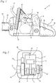
- FIG. 1 1 shows a chainsaw 21 as an exemplary embodiment of a hand-held working device in which the method according to the invention can be used to operate a two-stroke engine , blowers, harvesters, lawnmowers or the like are used.
- the chainsaw 21 has a housing 22, which can be composed of several housing parts and does not have to be closed.
- a two-stroke engine 1 is arranged in the housing 22 .
- the two-stroke engine 1 has an intake duct 14 via which air is sucked through an air filter 34 during operation.
- a rear handle 25 and a handle bar 26 are provided for guiding the chainsaw 21 during operation.
- On the housing 22, a guide rail 23 is fixed, on which a saw chain 24 is arranged circumferentially.
- the saw chain 24 is driven by the two-stroke engine 1 .
- Operating elements for operating the two-stroke engine 1 are advantageously arranged on the rear handle 25 .
- a throttle lever 35 is arranged on the rear handle 25, with which the position of an induction channel 14 arranged in 1 not shown throttle element 16 ( 3 ) can be changed.
- a throttle trigger lock 80 is also arranged on the rear handle 25 and mechanically blocks the throttle trigger 35 in the non-actuated state.
- the two-stroke engine 1 has a cylinder 2 in which a piston 5 is mounted reciprocatingly.
- the piston 5 delimits a combustion chamber 3 .
- a spark plug 20 which is controlled by a control device 31 , protrudes into the combustion chamber 3 .
- the piston 5 drives one in one Crankcase 4 about an axis of rotation 8 rotatably mounted crankshaft 7 at.
- the crankshaft 7 carries a flywheel 30.
- the flywheel 30 can advantageously be designed as a fan wheel which conveys cooling air to the cylinder 2.
- the control device 31 can include an ignition module in which a voltage is induced by magnets arranged on the flywheel 30 .
- the control device 31 is advantageously arranged on the outer circumference of the flywheel 30 .
- the control device 31 can also be connected to a generator which is connected to the crankshaft 7 and generates the energy for generating the ignition spark.
- a starting device 29 for starting the two-stroke engine 1 is also arranged on the crankshaft 7 .
- the starting device 29 is a pull-rope starter and has the 1 Starter grip 28 shown schematically.
- the pull starter is advantageously used for manual starting by an operator.
- the starter device 29 can also be an electrically driven starter device.
- a centrifugal clutch 32 is connected to the crankshaft 7 on the side of the crankcase 4 opposite the flywheel 30 .
- the output side of the centrifugal clutch 32 carries a drive pinion 33 which drives the saw chain 24 .
- As the output side of the centrifugal clutch 32 is in 2 schematically shown a clutch bell.
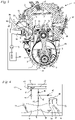
- the intake port 14 ends with an intake port opening 15 on the cylinder bore 17.
- the intake port opening 15 is controlled by the piston 5 and opens and closes depending on the position of the piston 5.
- the intake port 14 is open via the Intake port opening 15 is connected to a crankcase interior 9 .
- the crankcase interior 9 is fluidically connected to the combustion chamber 3 via overflow channels 10 and 12 .
- an overflow channel 10 close to the inlet is shown, which, with an overflow window 11, leads into the combustion chamber 3 opens out, as well as an overflow channel 12 close to the outlet, which opens out into the combustion chamber with an overflow window 13 .
- two overflow ducts 10 located near the inlet and two opposite overflow ducts 12 near the outlet are combined to form a common overflow duct and open at a common orifice opening 56 into the crankcase interior 9.
- each overflow duct 10, 12 opens into the crankcase interior 9 with a separate orifice 56 .
- An outlet opening 37 leads out of the combustion chamber 3 and is followed by an outlet channel 38 .
- the outlet opening 37 is also controlled by the piston 5 .
- the outlet channel 38 preferably opens into an exhaust gas silencer 57, from which 3 only the area of the inlet opening for exhaust gas is shown.
- the two-stroke engine 1 has the supply of fuel 3 a fuel valve 18 on.
- the fuel valve 18 is designed as an electromagnetic valve. Fuel is supplied to the fuel valve 18 from a fuel tank 59 by a fuel pump 45 .
- the fuel pump 45 is in particular a membrane pump driven by the fluctuating pressure in the crankcase interior 9 .
- the fuel valve 18 is activated by the control device 31 .
- the fuel valve 18 can be a normally open valve or a normally closed valve.
- the fuel valve 18 has an outlet opening 19 through which the fuel metered by the fuel valve 18 exits into the intake channel 14 .
- the fuel valve 18 meters the total amount of fuel supplied to the two-stroke engine 1 . Further fuel valves or fuel openings via which fuel is supplied are preferably not provided.
- a throttle element 16, a throttle valve in the exemplary embodiment, is arranged in the intake passage 14.
- the position of the throttle element 16 can be set via the throttle lever 35 ( figure 1 ) adjustable by the operator. With this, the operator can adjust the amount of air supplied to the two-stroke engine 1 .
- the control device 31 controls the fuel valve 18 in relation to consecutive blocks of several consecutive revolutions of the crankshaft 7, as explained in more detail below Figures 5 and 6 is described.
- the control device 31 determines the point in time at which the fuel valve 18 is closed for each block of several revolutions of the crankshaft 7 .
- the point in time at which the fuel valve 18 is opened in each block of revolutions of the crankshaft is advantageously fixed in the control device 31 .
- it can also be provided that the opening time of the fuel valve 18 is determined.
- the determination of the opening duration of the fuel valve 18 by the control device 31 is based on parameters. These parameters advantageously take into account boundary conditions, engine conditions and/or environmental conditions.
- the control device 31 also takes into account that the fuel valve 18 has a non-linear delivery behavior, as explained below 7 is described.
- a parameter that the control device 31 takes into account when determining the opening duration of the fuel valve 18 can be the position of the throttle element 16 .
- a sensor 36 is advantageously provided for detecting the position of the throttle element 16 .
- the sensor 36 is advantageously arranged outside the intake duct 14, in 3 i.e. in front of or behind the plane of the page, and therefore shown with a dashed line.
- a pressure of the two-stroke engine 1 is advantageously detected.
- a pressure sensor 39 is provided, which detects the pressure in the crankcase interior 9 .
- the pressure sensor 39 is arranged on the crankcase 45 .
- a pressure sensor 39' can be provided, which detects the pressure in the intake port 14.
- a temperature sensor 55 for detecting the temperature in the crankcase interior 9 can be provided be.
- the temperature of the intake air in intake duct 14 can be detected.
- a temperature sensor 55' is shown schematically. Additional and/or other parameters can also be used to determine the opening duration of fuel valve 18 .
- the fuel valve 18 meters the fuel directly into the intake port 14 .
- the fuel valve 18 can be arranged in a carburetor 40 in which the fuel is sucked in due to the negative pressure prevailing in the intake passage 14 .
- a carburetor 40 is shown schematically in 4 shown.
- the carburetor 40 has a fuel pump 45 for delivering fuel.
- the fuel pump 45 is preferably a diaphragm pump which is driven in particular by the fluctuating pressure in the crankcase interior 9 .
- the carburetor 40 includes a control chamber 41 which is separated from a compensation chamber 42 by a control diaphragm 43 .
- an inlet valve 44 which opens or closes depending on the position of the control diaphragm 43 .
- Fuel is supplied from the control chamber 41 to the electromagnetic fuel valve 18 via an adjustable throttle 46 . From there, the fuel reaches the outlet opening 19 via a non-return valve 48. The outlet opening 19 opens into the intake channel 14 in the area of a venturi 54.
- the fuel metered by the electromagnetic fuel valve 18 is also conducted via an adjustable throttle 47 to a fuel chamber 49, which is connected via fuel lines with fixed throttles at outlet openings 50, 51 and 52 opens into the intake port 14.
- the outlet opening 50 is a partial-load opening which, with respect to the direction of flow 58 in the intake port 14 , opens into the intake port 14 upstream of the throttle element 16 .
- the fuel ports 51 and 52 are idle fuel ports. When the throttle element 16 is open, air enters the fuel chamber 49 via the fuel opening 51 and the mixture formed here exits via the outlet opening 52 into the intake channel 14 .
- a choke element 53 is arranged in the intake port 14 upstream of the throttle element 15 in relation to the direction of flow 58 in the intake port 14 , which is directed toward the intake port opening 15 .
- the negative pressure at the outlet openings 19 and 50 to 52 can be increased during the starting process via the choke element 53 in order to increase the quantity of fuel supplied during the starting process.
- the entire fuel quantity supplied from the intake passage 14 is controlled by the electromagnetic fuel valve 18.
- figure 5 shows the activation of the fuel valve 18 provided according to the invention by means of a curve 60, which shows the current I, with which the fuel valve 18 is energized, over the crankshaft angle ⁇ .
- the curve 61 shows the course of the pressure p in the intake port 14.
- a subsequent block 69 also includes revolutions 62 to 67 of the crankshaft 7.
- the number of revolutions of the crankshaft per block 68, 69, 70 is the same for all blocks 68, 69, 70.
- the number of revolutions of the crankshaft 7 per block 68 to 70 is from 2 to 20 revolutions 62 to 67.
- Each block 68 to 70 advantageously comprises from 3 to 12, in particular from 4 to 10 revolutions of the crankshaft 7.
- 6 revolutions are 62 to 67 of the crankshaft 7 per block 68 to 70 are provided. 6 revolutions of the crankshaft 7 per block 68 to 70 are considered particularly preferred.
- Each block 68 to 70 extends over a crankshaft angle ⁇ , which corresponds to the number of revolutions of the crankshaft 7 per block 68 to 70 multiplied by 360° crankshaft angle. All blocks 68, 69 and 70 follow one another immediately. Each block includes an integer number of revolutions of the crankshaft 7.
- each block 68 to 70 designates a time interval which corresponds to an integer multiple of 360° crankshaft angle.
- the state of the fuel valve 18 is in 5 and 6 Schematically marked with the letters "G" for closed and "O" for open. As figure 5 shows, the opening and closing of the fuel valve 18 takes place with a slight time delay to the start of the current flow due to the inertia of the system.
- the fuel valve 18 opens at a crankshaft angle ⁇ 1 .
- the fuel valve 18 closes at a subsequent crankshaft angle ⁇ 2 figure 5 it is a normally closed valve. If the fuel valve 18 is open when de-energized, the energization takes place in the opposite way.
- the crankshaft angle ⁇ 1 is just before the intake port opening 15 opens, so that the fuel valve 18 is open when negative pressure builds up in the intake port 14, as the curve 61 shows.
- the opening duration tö which elapses from the crankshaft angle ⁇ 1 when opening to the crankshaft angle ⁇ 2 when closing the fuel valve 18, is significantly less than 360°.
- the fuel valve 18 is therefore at in figure 5 shown opening time tö for idling over less than one revolution of the crankshaft 7 open.
- the opening of the fuel valve 18 indicates when the fuel valve 18 is fully open and the closing of the fuel valve 18 indicates when the fuel valve 18 is fully closed.
- crankshaft angle ⁇ 1 is for idling ( figure 5 ) and rated speed ( 6 ) same.
- the crankshaft angle ⁇ 1 at which the fuel valve 18 is opened at least for all quasi-stationary operating states of the two-stroke engine 1 - possibly with the exception of the starting process and except for transient states of the two-stroke engine - the same.
- the fuel valve 18 can be opened at the crankshaft angle ⁇ 1 or at another crankshaft angle. If the current block is aborted and a new block is started when a desire to accelerate is detected, ie a rapid opening of the throttle element, fuel valve 18 can be opened again at the same crankshaft angle ⁇ 1 in relation to this new block.
- the beginning of the energization of the fuel valve 18 is chosen to be adapted to the desired opening time for all operating states. The end of the energization is adjusted to the desired closing time for all operating states.
- fuel valve 18 is closed in the exemplary embodiment at a crankshaft angle ⁇ 3 that lies within fourth revolution 65 of crankshaft 7 within block 71 .
- the opening duration tö at the nominal speed is significantly longer than the opening duration tö of the fuel valve 18 when idling.
- the opening duration tö extends over more than three complete revolutions 63, 64, 65 of the crankshaft 7 at nominal speed.
- a longer or shorter opening duration tö can also be advantageous.
- the crankshaft angle ⁇ 2 or ⁇ 3 at which the fuel valve 18 is closed is determined by the control device 31 on the basis of parameters.
- the parameters can be the position of the throttle element 16, the pressure in the crankcase interior 9, a temperature of the two-stroke engine 1, for example in the crankcase interior 9 or in the intake port 14, or a component temperature of the two-stroke engine 1 and/or the speed of the two-stroke engine 1. Multiple parameters are preferred for determination used at the time of closing.
- the determination of the opening duration tö in particular the determination of the crankshaft angle ⁇ 2 or ⁇ 3 at which the fuel valve 18 is closed, is preferably determined using a map that specifies one or more parameters over the speed of the two-stroke engine 1 .
- the map can, for example, specify the opening duration tö over the engine speed and the throttle valve angle.
- the delivery characteristic of the fuel valve 18 is non-linear. This is in 7 shown schematically.
- a curve 75 is shown with a dashed line, which as a comparison curve indicates a linear relationship between the fuel quantity x supplied and the time t.
- the curve 74 schematically reproduces the actual progression of the fuel quantity x supplied over time t.
- the curve 74 thus describes the delivery characteristics.
- the curve 74 fluctuates.
- the fluctuations of the curve 74 result, on the one hand, from the fluctuating pressure in the intake passage 14 and, on the other hand, from the inertia of the fuel column to be moved when fuel is supplied. This results in a delayed beginning and a delayed end of the actual fuel supply compared to the opening time and closing time of fuel valve 18.
- crankshaft angle ⁇ 2 or ⁇ 3 at which the fuel valve 18 is closed is determined for each block 68 to 73 of revolutions 62 to 67 of the crankshaft 7, it is possible to react to changed operating conditions, for example if the operator wants to accelerate expressed in the opening of the throttle element 16, can be reacted to quickly.
- the operating conditions are advantageously recorded for each revolution 62 to 67 of the crankshaft 7 .
- Particularly advantageous is the crankshaft angle ⁇ 2 or ⁇ 3 in the event that the fuel valve 18 in the current Block 68 to 73 is still open, changed immediately depending on the changed operating conditions.
- the changed operating condition is advantageously taken into account for the subsequent block 68 to 73 of revolutions of the crankshaft 7. Provision can be made to abort the current block 68 to 73 and to start a new block 68 to 73 immediately with regard to the activation of the fuel valve 18 .
- fuel valve 18 is actuated for at least one, in particular for all, quasi-stationary states of the two-stroke engine in such a way that fuel valve 18 is opened and closed exactly once in relation to blocks 68 to 73 of successive revolutions of the crankshaft within each block 68 to 73 that follow without interruption will.
Landscapes
- Engineering & Computer Science (AREA)
- Chemical & Material Sciences (AREA)
- Combustion & Propulsion (AREA)
- Mechanical Engineering (AREA)
- General Engineering & Computer Science (AREA)
- Electrical Control Of Air Or Fuel Supplied To Internal-Combustion Engine (AREA)
Abstract
Description
- Die Erfindung betrifft ein Verfahren zum Betrieb eines Zweitaktmotors der im Oberbegriff des Anspruchs 1 angegebenen Gattung.
- Es ist bekannt, Zweitaktmotoren den für den Betrieb benötigten Kraftstoff über ein elektromagnetisches Kraftstoffventil zuzudosieren. Der Kraftstoff wird dabei üblicherweise für jeden Motorzyklus zudosiert. Dabei wird das Kraftstoffventil innerhalb eines Motorzyklus einmal geöffnet und einmal geschlossen. Dadurch ergeben sich insbesondere bei Volllast wie beispielsweise bei Nenndrehzahl oder in der Enddrehzahl sehr kurze Schaltzeiten. Um diese realisieren zu können, muss ein recht aufwändig gestaltetes elektromagnetisches Ventil mit hohem Energiebedarf zum Einsatz kommen.
- Um diese sehr kurzen Schaltzeiten bei hohen Drehzahlen zu vermeiden, ist es aus der
DE 10 2013 012 135 A1 bekannt, das Kraftstoffventil im Leerlauf mit einer Frequenz zu öffnen, die auf das Öffnen und Schließen des Ansaugkanals abgestimmt ist. Die Kraftstoffzufuhr im Leerlauf erfolgt daher synchron zu den Motorzyklen. In Volllast ist vorgesehen, das elektromagnetische Ventil unabhängig von der Frequenz, mit der der Ansaugkanal mit dem Kurbelgehäuseinnenraum verbunden wird, also unabhängig von den Motorzyklen, zu öffnen. Dadurch muss das Kraftstoffventil bei Volllast nicht bei jedem Motorzyklus geöffnet und geschlossen werden, sondern kann seltener geöffnet und geschlossen werden, wodurch der Einsatz eines einfacher aufgebauten Ventils möglich wird. - Es hat sich gezeigt, dass die Umschaltung der Betriebsweise des Kraftstoffventils von einem zu den Motorzyklen synchronen Betrieb zu einem zu den Motorzyklen asynchronen Betrieb bei ungünstiger Wahl des Umschaltzeitpunkts vom Bediener wahrnehmbar ist. Dies ist unerwünscht.
- Der vorliegenden Erfindung liegt die Aufgabe zugrunde, ein Verfahren zum Betrieb eines Zweitaktmotors bereitzustellen, das für alle Betriebszustände des Verbrennungsmotors mit Ausnahme des Anwerfvorgangs anwendbar ist und den Einsatz eines einfach aufgebauten Ventils ermöglicht.
- Diese Aufgabe wird durch ein Verfahren zum Betrieb eines Zweitaktmotors mit den Merkmalen des Anspruchs 1 gelöst.
- Erfindungsgemäß ist vorgesehen, mehrere aufeinander folgende Umdrehungen der Kurbelwelle zu einem Block zusammenzufassen und die Ansteuerung des Kraftstoffventils zumindest in einem quasistationären Zustand des Zweitaktmotors bezogen auf unterbrechungsfrei aufeinander folgende Blöcke von Umdrehungen der Kurbelwelle durchzuführen. Innerhalb jedes Blocks von Umdrehungen der Kurbelwelle wird das Kraftstoffventil zumindest in dem quasistationären Zustand genau einmal geöffnet und genau einmal geschlossen. Jeder Block umfasst dabei von 2 bis 20 Umdrehungen der Kurbelwelle. Der Begriff "Block" beschreibt die Zusammenschau von mehreren Kurbelwellenumdrehungen in der Steuereinrichtung. Der Block von Kurbelwellenumdrehungen wird bezogen auf die Ansteuerung des Kraftstoffventils in der Steuereinrichtung gemeinsam betrachtet. Das Kraftstoffventil wird nicht bezogen auf einzelne Umdrehungen der Kurbelwelle, sondern bezogen auf einen Block von Kurbelwellenumdrehungen angesteuert.
- Dadurch, dass jeder Block mindestens zwei Umdrehungen der Kurbelwelle umfasst und das Kraftstoffventil in mindestens einem quasistationären Zustand des Zweitaktmotors innerhalb des Blocks genau einmal geöffnet und geschlossen wird, stehen auch bei hohen Drehzahlen wie bei Nenndrehzahl oder Enddrehzahl ausreichend lange Zeiten für die Ansteuerung des Kraftstoffventils bereit, so dass der Einsatz eines vergleichsweise einfach aufgebauten elektromagnetischen Kraftstoffventils ermöglicht wird. Dadurch, dass die Ansteuerung des Kraftstoffventils sowohl für den Leerlauf als auch für hohe Drehzahlen jeweils für einen Block von aufeinander folgenden Umdrehungen der Kurbelwelle erfolgt, wird ein Umschalten zwischen einer zu den Motorzyklen synchronen Ansteuerung und einer zu den Motorzyklen asynchronen Ansteuerung des elektromagnetischen Ventils vermieden. Die Ansteuerung des elektromagnetischen Kraftstoffventils erfolgt immer synchron zu aufeinanderfolgenden Blöcken, die jeweils die gleiche Anzahl von Umdrehungen der Kurbelwelle umfassen.
- Vorzugsweise erfolgt die Ansteuerung des Kraftstoffventils nach dem Anwerfvorgang in allen quasistationären Zuständen des Zweitaktmotors derart, dass das Kraftstoffventil bezogen auf unterbrechungsfrei aufeinanderfolgende Blöcke von aufeinanderfolgenden Umdrehungen der Kurbelwelle innerhalb jedes Blocks genau einmal geöffnet und geschlossen wird.
- Lediglich während des Anwerfvorgangs und während nicht stationären Zuständen kann eine abweichende Ansteuerung des Kraftstoffventils vorteilhaft sein. Da während des Anwerfvorgangs die Drehzahlen vergleichsweise gering sind, ist die Ansteuerung des Kraftstoffventils während des Anwerfvorgangs für die benötigte Schaltzeit des elektromagnetischen Ventils unkritisch. Der Anwerfvorgang erfolgt vorteilhaft durch einen manuellen Handzugstarter. Dieser wird zum Start vom Bediener betätigt.
- Die Nenndrehzahl des Zweitaktmotors kann beispielsweise zwischen 9.000 Umdrehungen/Minute bis 12.000 Umdrehungen/Minute betragen. Die Enddrehzahl des Zweitaktmotors kann beispielweise zwischen 12.000 Umdrehungen/Minute und 17.000 Umdrehungen/Minute betragen.
- Quasistationäre Zustände des Zweitaktmotors sind vorliegend zumindest alle Zustände, bei denen das Drosselelement über einen Kurbelwellenwinkel von 360° um weniger als 10% der maximalen Verstellung des Drosselelements verstellt wird. Insbesondere sind quasistationäre Zustände des Zweitaktmotors alle Zustände, bei denen das Drosselelement über einen Kurbelwellenwinkel von 360° um weniger als 20% der maximalen Verstellung des Drosselelements verstellt wird. Zustände, bei denen das Drosselelement sehr schnell verstellt wird, beispielsweise Beschleunigungszustände und Verzögerungszustände, sind demnach keine quasistationären Zustände. Beim schnellen Beschleunigen und schnellen Verzögern ändert sich der Kraftstoffbedarf des Zweitaktmotors schlagartig. Dies kann eine Ansteuerung des Kraftstoffventils erfordern, die von der blockweisen Ansteuerung mit genau einem Öffnen und Schließen des Kraftstoffventils je Block abweicht.
- Die maximale Verstellung des Drosselelements entspricht der Verstellbewegung, die das Drosselelement zwischen seiner ersten Endlage und seiner zweiten Endlage zurücklegt. Üblicherweise ist das Drosselelement schwenkbar gelagert, so dass der maximale Verstellweg dem Verschwenkwinkel des Drosselelements zwischen seinen Endlagen entspricht.
- Vorteilhaft ist der Kurbelgehäuseinnenraum in mindestens einer Stellung des Kolbens über mindestens einen Überströmkanal fluidisch mit dem Brennraum verbunden. Der Ansaugkanal mündet vorteilhaft über eine von dem Kolben gesteuerte Ansaugkanalöffnung an der Zylinderbohrung in den Kurbelgehäuseinnenraum.
- Bevorzugt wird das Kraftstoffventil zumindest in dem mindestens einen, insbesondere zumindest in allen quasistationären Zuständen innerhalb jedes Blocks zum gleichen Kurbelwellenwinkel innerhalb des Blocks geöffnet. Insbesondere im Leerlauf, wenn das Kraftstoffventil eine vergleichsweise kurze Öffnungszeit aufweist, kann durch geeignete Wahl des Kurbelwellenwinkels, zu dem das Kraftstoffventil innerhalb des Blocks geöffnet wird, eine Abstimmung auf den im Kurbelgehäuseinnenraum herrschenden Druck während des Öffnungszeitraums erreicht werden. Dadurch, dass die Öffnung des Kraftstoffventils innerhalb jedes Blocks zum gleichen Kurbelwellenwinkel des Blocks erfolgt, muss von der Steuereinrichtung lediglich der Schließzeitpunkt des Kraftstoffventils festgelegt werden, so dass sich eine einfache Ansteuerung ergibt. Die Öffnung des Kraftstoffventils im Leerlauf ist vorteilhaft vergleichsweise kurz, da der Zweitaktmotor im Leerlauf vergleichsweise geringe Kraftstoffmengen benötigt.
- Vorteilhaft wird das Kraftstoffventil in mindestens einem Betriebszustand innerhalb eines Blocks über einen Kurbelwellenwinkel von mehr als 360° geöffnet. Dadurch, dass das Kraftstoffventil über mehr als 360°, also über mehr als eine vollständige Umdrehung der Kurbelwelle geöffnet wird, kann eine vergleichsweise große Kraftstoffmenge zugeführt werden. Dies ist insbesondere bei hohen Drehzahlen, beispielsweise bei Volllast, vorteilhaft.
- Die Anzahl der Umdrehungen der Kurbelwelle je Block ist vorteilhaft als konstanter Wert in der Steuereinrichtung abgespeichert. Die Anzahl der Umdrehungen der Kurbelwelle je Block ist bevorzugt zumindest für alle quasistationären Betriebszustände nicht veränderbar. Die Anzahl der Umdrehungen der Kurbelwelle je Block ist für alle quasistationären Betriebszustände gleich. Für nicht stationäre Zustände kann die Anzahl der Umdrehungen der Kurbelwelle je Block abweichen, insbesondere dann, wenn die blockweise Ansteuerung des Kraftstoffventils innerhalb eines Blocks aufgrund einer Erkennung einer Beschleunigung abgebrochen und unmittelbar ein neuer Block gestartet wird.
- Vorteilhaft ermittelt die Steuereinrichtung die gewünschte Öffnungsdauer des Kraftstoffventils anhand mindestens eines Parameters. Der mindestens eine Parameter kann von Randbedingungen, von Triebwerksbedingungen und/oder Umgebungsbedingungen abhängen. Triebwerksbedingungen können beispielsweise Temperatur und/oder Druck des Antriebsmotors sein. Umgebungsbedingungen können beispielsweise der Umgebungsdruck oder die Umgebungstemperatur sein. Randbedingungen können beispielsweise der Verschmutzungsgrad eines Luftfilters oder die an einem Werkzeug eines von dem Zweitaktmotor angetriebenen Arbeitsgeräts anliegende Last sein.
- Bevorzugt wird bei der Ermittlung der Öffnungsdauer des Kraftstoffventils die nichtlineare Fördercharakteristik des Kraftstoffs in den Ansaugkanal berücksichtigt. Es hat sich gezeigt, dass die dem Ansaugkanal zugeführte Kraftstoffmenge nicht linear von der Öffnungsdauer des Kraftstoffventils abhängt. Die nichtlineare Fördercharakteristik des Kraftstoffs in den Ansaugkanal ist zum einen bedingt von Druckschwankungen an der Austrittsöffnung, an der der Kraftstoff in den Ansaugkanal übertritt. Zum anderen hat sich gezeigt, dass die im System vorhandene Kraftstoffsäule träge reagiert und beim Öffnen des Kraftstoffventils zunächst die Kraftstoffsäule in Bewegung versetzt werden muss. Beim Schließen des Kraftstoffventils kann selbst dann, wenn kein signifikanter Unterdruck im Ansaugkanal herrscht, noch Kraftstoff aufgrund der Trägheit der Kraftstoffsäule in den Ansaugkanal austreten. Die Ermittlung des Schließzeitpunkts des Kraftstoffventils erfolgt bevorzugt unter Berücksichtigung dieses nichtlinearen Verhaltens. Der Kraftstoff steht vor der Kraftstofföffnung vorteilhaft nicht unter Vordruck. Der Kraftstoff ist vorteilhaft nicht druckbeaufschlagt, sondern wird mittels des im Ansaugkanal entstehenden Unterdrucks aus mindestens einer Kraftstofföffnung gefördert. Das Kraftstoffventil erlaubt in geöffnetem Zustand die Förderung von Kraftstoff aus der mindestens einen Kraftstofföffnung mittels Unterdruck.
- Es kann vorgesehen sein, dass der Zweitaktmotor ein Drosselelement im Ansaugkanal aufweist. Ein solches Drosselelement ist vorteilhaft vorgesehen, um den freien Strömungsquerschnitt des Ansaugkanals zu steuern. Es kann vorgesehen sein, dass die Stellung des Drosselelements mittels eines Sensors erfasst wird. In vorteilhafter Gestaltung ist die erfasste Stellung des Drosselelements ein Parameter, der zur Ermittlung der Öffnungsdauer des Kraftstoffventils genutzt wird.
- Alternativ oder zusätzlich kann ein Drucksensor zur Erfassung des Drucks im Kurbelgehäuseinnenraum und/oder zur Erfassung des Drucks im Ansaugkanal vorgesehen sein. Der ermittelte Druck ist insbesondere ein Parameter, der zur Ermittlung der Öffnungsdauer des Kraftstoffventils genutzt wird. Der Druck kann auch genutzt werden, um eine Verstellung des Drosselelements zu erfassen. Alternativ kann ein Sensor zur Ermittlung der Position des Drosselelements vorgesehen sein.
- Alternativ oder zusätzlich kann ein Temperatursensor vorgesehen sein. Vorteilhaft ist die ermittelte Temperatur ein Parameter, der zur Ermittlung der Öffnungsdauer des Kraftstoffventils genutzt wird. Der Temperatursensor ist vorteilhaft zur Ermittlung der Temperatur im Kurbelgehäuseinnenraum oder zur Ermittlung der Temperatur der angesaugten Luft im Ansaugkanal vorgesehen. Alternativ kann auch vorgesehen sein, dass der Temperatursensor eine Bauteiltemperatur des Zweitaktmotors wie beispielsweise die Temperatur des Zylinders oder des Kurbelgehäuses erfasst. Auch mehrere Temperatursensoren zur Ermittlung unterschiedlicher Temperaturen können vorgesehen sein.
- Die Öffnungsdauer des Kraftstoffventils wird insbesondere anhand der Drehzahl des Zweitaktmotors ermittelt. In bevorzugter Gestaltung wird die Öffnungsdauer des Kraftstoffventils über ein Kennfeld ermittelt. In alternativer Gestaltung kann vorgesehen sein, dass die Öffnungsdauer des Kraftstoffventils berechnet wird.
- Bevorzugt umfasst jeder Block von 3 bis 12, insbesondere von 4 bis 10, vorzugsweise 6 Umdrehungen in der Kurbelwelle. Es hat sich gezeigt, dass bei sehr geringer Anzahl der Umdrehungen der Kurbelwelle je Block die Schaltzeiten des elektromagnetischen Ventils einen erheblichen Einfluss auf die Öffnungszeiten und damit auf die geförderte Kraftstoffmenge haben. Bei einer geringen Anzahl von Umdrehungen der Kurbelwelle je Block ist daher die exakte Dosierung von Kraftstoff schwierig, oder es muss ein vergleichsweise hochwertiges elektromagnetisches Ventil zum Einsatz kommen. Ist die Anzahl der Umdrehungen der Kurbelwelle je Block vergleichsweise hoch, insbesondere größer als 12 Umdrehungen je Block, so kann sich im Brennraum ein inhomogenes Gemisch bilden, da der Kurbelgehäuseinnenraum und der Ansaugkanal zur Zwischenspeicherung des Kraftstoffs nicht ausreichen. Dadurch kann sich ein ungleichmäßiges Betriebsverhalten des Zweitaktmotors ergeben. Diese Nachteile können durch geeignete Wahl der Anzahl von Umdrehungen der Kurbelwelle je Block vermieden werden.
- Die Ansteuerung des Kraftstoffventils bezogen auf unterbrechungsfrei aufeinanderfolgende Blöcke von aufeinanderfolgenden Umdrehungen der Kurbelwelle kann im Fall von Beschleunigung oder Verzögerung nachteilig sein, da bei Beschleunigungsvorgängen die zudosierte Kraftstoffmenge im aktuellen Block zu gering und bei Verzögerungsvorgängen die zudosierte Kraftstoffmenge zu groß sein kann. Um auch beim Beschleunigen und beim Verzögern ein gutes Betriebsverhalten und schnelles Ansprechen des Zweitaktmotors zu erzielen, ist vorteilhaft vorgesehen, dass die Ansteuerung des Kraftstoffventils von der Ansteuerung bezogen auf unterbrechungsfrei aufeinanderfolgende Blöcke von aufeinanderfolgenden Umdrehungen der Kurbelwelle, in denen das Kraftstoffventil genau einmal geöffnet und geschlossen wird, abweicht, wenn ein Beschleunigungszustand oder ein Verzögerungszustand erkannt wird.
- Wenn die Ansteuerung des Kraftstoffventils von der Ansteuerung bezogen auf unterbrechungsfrei aufeinanderfolgende Blöcke, in denen das Kraftstoffventil genau einmal geöffnet und geschlossen wird, abweicht, kann das Kraftstoffventil häufiger oder seltener als genau einmal je Block geöffnet werden. Alternativ kann vorgesehen sein, die Anzahl der Umdrehungen der Kurbelwelle je Block zu ändern. Besonders bevorzugt kann bei Erkennung einer Beschleunigung das Kraftstoffventil im aktuellen Block länger offen gehalten werden, wenn das Kraftstoffventil bei der Erkennung einer Beschleunigung noch geöffnet ist. Ist das Kraftstoffventil bereits geschlossen, so kann das Kraftstoffventil erneut geöffnet werden. Alternativ kann der aktuelle Block von Umdrehungen der Kurbelwelle abgebrochen und unmittelbar ein neuer Block gestartet werden. Dadurch ist die Anzahl der Umdrehungen der Kurbelwelle für den Block, innerhalb dessen die Beschleunigung erkannt wurde, geringer. Für den folgenden, unmittelbar nach Erkennung der Beschleunigung begonnenen Block kann die Anzahl der Umdrehungen der Kurbelwelle wieder den ursprünglichen Wert annehmen und die gewünschte Kraftstoffmenge durch geeignete Wahl des Schließzeitpunkts des Kraftstoffventils gesteuert werden. Wird eine Verzögerung erkannt, so kann das Kraftstoffventil über einen Block von Umdrehungen der Kurbelwelle geschlossen gehalten werden. Auch eine Erhöhung der Anzahl der Umdrehungen der Kurbelwelle je Block kann für den Verzögerungsfall vorgesehen sein.
- Beim Beschleunigen und Verzögern handelt es sich um instationäre Zustände, in denen das Drosselelement über einen Kurbelwellenwinkel von 360° um mehr als 10%, insbesondere mehr als 20%, bevorzugt um mehr als 30% der maximalen Verstellung des Drosselelements verstellt wird.
- Ein Ausführungsbeispiel der Erfindung wird im Folgenden anhand der Zeichnung erläutert. Es zeigen:
- Fig. 1
- eine schematische Darstellung einer Motorsäge mit einem Zweitaktmotor,
- Fig. 2
- eine schematische Schnittdarstellung durch die Motorsäge aus
Fig. 1 , - Fig. 3
- eine schematische Darstellung eines Schnitts durch den Zweitaktmotor der Motorsäge aus
Fig. 1 , - Fig. 4
- eine schematische Darstellung eines Vergasers, der alternativ zur Kraftstoffzufuhr zu dem Zweitaktmotor aus
Fig. 3 zum Einsatz kommen kann, - Fig. 5
- eine schematische Darstellung der Bestromung des elektromagnetischen Ventils und des Druckverlaufs im Kurbelgehäuseinnenraum über dem Kurbelwellenwinkel für den Leerlauf,
- Fig. 6
- eine schematische Darstellung entsprechend
Fig. 5 für die Nenndrehzahl, - Fig. 7
- eine schematische Darstellung der geförderten Kraftstoffmenge durch das elektromagnetische Ventil über der Zeit.
-
Fig. 1 zeigt als Ausführungsbeispiel für ein handgeführtes Arbeitsgerät, bei dem das erfindungsgemäße Verfahren zum Betrieb eines Zweitaktmotors eingesetzt werden kann, eine Motorsäge 21. Das erfindungsgemäße Verfahren kann auch bei anderen Zweitaktmotoren 1, insbesondere bei Zweitaktmotoren in anderen Arbeitsgeräten, bevorzugt handgeführten Arbeitsgeräten wie beispielsweise Trennschleifern, Freischneidern, Blasgeräten, Erntegeräten, Rasenmähern oder dergleichen zum Einsatz kommen. - Die Motorsäge 21 besitzt ein Gehäuse 22, das aus mehreren Gehäuseteilen zusammengesetzt sein kann und nicht geschlossen ausgebildet sein muss. Im Gehäuse 22 ist ein Zweitaktmotor 1 angeordnet. Der Zweitaktmotor 1 weist einen Ansaugkanal 14 auf, über den im Betrieb Luft durch einen Luftfilter 34 gesaugt wird. Zum Führen der Motorsäge 21 im Betrieb sind ein hinterer Handgriff 25 sowie ein Griffbügel 26 vorgesehen. Am Gehäuse 22 ist eine Führungsschiene 23 festgelegt, an der eine Sägekette 24 umlaufend angeordnet ist. Die Sägekette 24 ist vom Zweitaktmotor 1 angetrieben. An der der Führungsschiene 23 zugewandten Seite des Griffbügels 26 ist ein Handschutz 27 angeordnet, der zur Auslösung einer nicht dargestellten Kettenbremse dienen kann. Am hinteren Handgriff 25 sind vorteilhaft Bedienelemente zur Bedienung des Zweitaktmotors 1 angeordnet. Im Ausführungsbeispiel ist ein Gashebel 35 am hinteren Handgriff 25 angeordnet, mit dem die Stellung eines im Ansaugkanal 14 angeordneten, in
Fig. 1 nicht dargestellten Drosselelements 16 (Fig. 3 ) verändert werden kann. Am hinteren Handgriff 25 ist außerdem eine Gashebelsperre 80 angeordnet, die in unbetätigtem Zustand den Gashebel 35 mechanisch blockiert. -
Fig. 2 zeigt schematisch den Aufbau des Triebwerks der Motorsäge 21. Der Zweitaktmotor 1 weist einen Zylinder 2 auf, in dem ein Kolben 5 hin- und hergehend gelagert ist. Der Kolben 5 begrenzt einen Brennraum 3. In den Brennraum 3 ragt eine Zündkerze 20, die von einer Steuereinrichtung 31 angesteuert ist. Der Kolben 5 treibt eine in einem Kurbelgehäuse 4 um eine Drehachse 8 drehbar gelagerte Kurbelwelle 7 an. Die Kurbelwelle 7 trägt im Ausführungsbeispiel ein Schwungrad 30. Das Schwungrad 30 kann vorteilhaft als Lüfterrad ausgebildet sein, das Kühlluft zum Zylinder 2 fördert. Die Steuereinrichtung 31 kann ein Zündmodul umfassen, in dem von am Schwungrad 30 angeordneten Magneten eine Spannung induziert wird. Hierzu ist die Steuereinrichtung 31 vorteilhaft am Außenumfang des Schwungrads 30 angeordnet. Alternativ kann die Steuereinrichtung 31 auch mit einem mit der Kurbelwelle 7 verbundenen Generator verbunden sein, der die Energie für die Erzeugung des Zündfunkens generiert. An der Kurbelwelle 7 ist außerdem eine Anwerfvorrichtung 29 zum Anwerfen des Zweitaktmotors 1 angeordnet. Die Anwerfvorrichtung 29 ist im Ausführungsbeispiel ein Seilzugstarter und weist den inFig. 1 schematisch dargestellten Anwerfgriff 28 auf. Der Seilzugstarter wird vorteilhaft zum manuellen Starten durch einen Bediener genutzt. Die Anwerfvorrichtung 29 kann jedoch auch eine elektrisch angetriebene Anwerfvorrichtung sein. Im Ausführungsbeispiel ist auf der dem Schwungrad 30 gegenüberliegenden Seite des Kurbelgehäuses 4 eine Fliehkraftkupplung 32 mit der Kurbelwelle 7 verbunden. Die Abtriebsseite der Fliehkraftkupplung 32 trägt ein Antriebsritzel 33, das die Sägekette 24 antreibt. Als Abtriebsseite der Fliehkraftkupplung 32 ist inFig. 2 schematisch eine Kupplungsglocke dargestellt. -
Fig. 3 zeigt den Aufbau des Zweitaktmotors 1 im Einzelnen. Der Kolben 5 ist in einer Zylinderbohrung 17 hin- und hergehend gelagert. Der Kolben 5 treibt die Kurbelwelle 7 über ein Pleuel 6 rotierend an. Der Ansaugkanal 14 mündet mit einer Ansaugkanalöffnung 15 an der Zylinderbohrung 17. Die Ansaugkanalöffnung 15 ist im Ausführungsbeispiel vom Kolben 5 gesteuert und öffnet und schließt in Abhängigkeit der Position des Kolbens 5. Im Bereich des oberen Totpunkts des Kolbens 5 ist der Ansaugkanal 14 über die geöffnete Ansaugkanalöffnung 15 mit einem Kurbelgehäuseinnenraum 9 verbunden. Im Bereich des unteren Totpunkts des Kolbens 5, der inFig. 3 dargestellt ist, ist der Kurbelgehäuseinnenraum 9 fluidisch über Überströmkanäle 10 und 12 mit dem Brennraum 3 verbunden. Im Ausführungsbeispiel ist ein einlassnaher Überströmkanal 10 dargestellt, der mit einem Überströmfenster 11 in den Brennraum 3 mündet, sowie ein auslassnaher Überströmkanal 12, der mit einem Überströmfenster 13 in den Brennraum mündet. Im Ausführungsbeispiel sind zwei auf gegenüberliegenden Seiten des Zylinders 2 angeordnete einlassnahe Überströmkanäle 10 und zwei einander gegenüberliegende auslassnahe Überströmkanäle 12 zu einem gemeinsamen Überströmkanal zusammengefasst und münden an einer gemeinsamen Mündungsöffnung 56 in den Kurbelgehäuseinnenraum 9. Es kann jedoch auch vorgesehen sein, dass jeder Überströmkanal 10, 12 mit einer separaten Mündungsöffnung 56 in den Kurbelgehäuseinnenraum 9 mündet. - Aus dem Brennraum 3 führt eine Auslassöffnung 37, an die ein Auslasskanal 38 anschließt. Die Auslassöffnung 37 ist ebenfalls vom Kolben 5 gesteuert. Der Auslasskanal 38 mündet bevorzugt in einen Abgasschalldämpfer 57, von dem in
Fig. 3 nur der Bereich der Einlassöffnung für Abgas dargestellt ist. - Zur Zufuhr von Kraftstoff weist der Zweitaktmotor 1 im Ausführungsbeispiel nach
Fig. 3 ein Kraftstoffventil 18 auf. Das Kraftstoffventil 18 ist als elektromagnetisches Ventil ausgebildet. Dem Kraftstoffventil 18 wird Kraftstoff aus einem Kraftstofftank 59 von einer Kraftstoffpumpe 45 zugeführt. Die Kraftstoffpumpe 45 ist insbesondere eine vom schwankenden Druck im Kurbelgehäuseinnenraum 9 angetriebene Membranpumpe. Das Kraftstoffventil 18 ist von der Steuereinrichtung 31 angesteuert. Das Kraftstoffventil 18 kann dabei ein stromlos offenes Ventil oder ein stromlos geschlossenes Ventil sein. Das Kraftstoffventil 18 weist eine Austrittsöffnung 19 auf, über die der vom Kraftstoffventil 18 zugemessene Kraftstoff in den Ansaugkanal 14 austritt. Das Kraftstoffventil 18 misst die gesamte dem Zweitaktmotor 1 zugeführte Kraftstoffmenge zu. Weitere Kraftstoffventile oder Kraftstofföffnungen, über die Kraftstoff zugeführt wird, sind vorzugsweise nicht vorgesehen. - Im Ansaugkanal 14 ist ein Drosselelement 16, im Ausführungsbeispiel eine Drosselklappe, angeordnet. Die Stellung des Drosselelements 16 ist über den Gashebel 35 (
Fig. 1 ) vom Bediener einstellbar. Damit kann der Bediener die dem Zweitaktmotor 1 zugeführte Menge an Luft einstellen. - Die Steuereinrichtung 31 steuert das Kraftstoffventil 18 bezogen auf aufeinanderfolgende Blöcke von mehreren aufeinanderfolgenden Umdrehungen der Kurbelwelle 7 an, wie im Folgenden noch ausführlich zu
Fig. 5 und 6 beschrieben wird. Die Steuereinrichtung 31 legt den Zeitpunkt, zu dem das Kraftstoffventil 18 geschlossen wird, für jeden Block von mehreren Umdrehungen der Kurbelwelle 7 fest. Der Zeitpunkt, zu dem das Kraftstoffventil 18 in jedem Block von Umdrehungen der Kurbelwelle geöffnet wird, ist vorteilhaft in der Steuereinrichtung 31 fest vorgegeben. In alternativer Gestaltung kann auch vorgesehen sein, dass der Öffnungszeitpunkt des Kraftstoffventils 18 ermittelt wird. Die Ermittlung der Öffnungsdauer des Kraftstoffventils 18 durch die Steuereinrichtung 31 erfolgt anhand von Parametern. Diese Parameter berücksichtigen vorteilhaft Randbedingungen, Triebwerksbedingungen und/oder Umgebungsbedingungen. Die Steuereinrichtung 31 berücksichtigt auch, dass das Kraftstoffventil 18 ein nichtlineares Förderverhalten aufweist, wie im Folgenden noch zuFig. 7 beschrieben wird. - Ein Parameter, den die Steuereinrichtung 31 bei der Ermittlung der Öffnungsdauer des Kraftstoffventils 18 berücksichtigt, kann die Stellung des Drosselelements 16 sein. Zur Erfassung der Stellung des Drosselelements 16 ist vorteilhaft ein Sensor 36 vorgesehen. Der Sensor 36 ist vorteilhaft außerhalb des Ansaugkanals 14 angeordnet, in
Fig. 3 also vor oder hinter der Blattebene, und daher mit gestrichelter Linie dargestellt. Alternativ oder zusätzlich wird vorteilhaft ein Druck des Zweitaktmotors 1 erfasst. Im Ausführungsbeispiel ist ein Drucksensor 39 vorgesehen, der den Druck im Kurbelgehäuseinnenraum 9 erfasst. Der Drucksensor 39 ist hierzu am Kurbelgehäuse 45 angeordnet. Alternativ oder zusätzlich kann ein Drucksensor 39' vorgesehen sein, der den Druck im Ansaugkanal 14 erfasst. Hierzu ist der inFig. 3 schematisch dargestellte Drucksensor 39' vorteilhaft am Ansaugkanal 14 angeordnet. Alternativ oder zusätzlich kann ein Temperatursensor 55 zur Erfassung der Temperatur im Kurbelgehäuseinnenraum 9 vorgesehen sein. Alternativ oder zusätzlich kann die Temperatur der angesaugten Luft im Ansaugkanal 14 erfasst werden. Hierzu ist inFig. 3 schematisch ein Temperatursensor 55' eingezeichnet. Auch weitere und/oder andere Parameter können zur Ermittlung der Öffnungsdauer des Kraftstoffventils 18 genutzt werden. - Beim Ausführungsbeispiel nach
Fig. 3 dosiert das Kraftstoffventil 18 den Kraftstoff unmittelbar in den Ansaugkanal 14 zu. Alternativ kann das Kraftstoffventil 18 in einem Vergaser 40 angeordnet sein, bei dem der Kraftstoff aufgrund des im Ansaugkanal 14 herrschenden Unterdrucks angesaugt wird. Ein solcher Vergaser 40 ist schematisch inFig. 4 dargestellt. Der Vergaser 40 weist eine Kraftstoffpumpe 45 zur Förderung von Kraftstoff auf. Die Kraftstoffpumpe 45 ist bevorzugt eine Membranpumpe, die insbesondere vom schwankenden Druck im Kurbelgehäuseinnenraum 9 angetrieben ist. Der Vergaser 40 umfasst eine Regelkammer 41, die von einer Kompensationskammer 42 über eine Regelmembran 43 getrennt ist. Am Eintritt in die Regelkammer 41 ist ein Einlassventil 44 angeordnet, das in Abhängigkeit der Stellung der Regelmembran 43 öffnet bzw. schließt. Aus der Regelkammer 41 wird Kraftstoff über eine einstellbare Drossel 46 zum elektromagnetischen Kraftstoffventil 18 zugeführt. Von dort gelangt der Kraftstoff über ein Rückschlagventil 48 zur Austrittsöffnung 19. Die Austrittsöffnung 19 mündet im Bereich eines Venturis 54 in den Ansaugkanal 14. Der vom elektromagnetischen Kraftstoffventil 18 zugemessene Kraftstoff wird außerdem über eine einstellbare Drossel 47 zu einer Kraftstoffkammer 49 geleitet, die über Kraftstoffleitungen mit Festdrosseln an Austrittsöffnungen 50, 51 und 52 in den Ansaugkanal 14 mündet. Die Austrittsöffnung 50 ist im Ausführungsbeispiel eine Teillastöffnung, die bezogen auf die Strömungsrichtung 58 im Ansaugkanal 14 stromauf des Drosselelements 16 in den Ansaugkanal 14 mündet. Die Kraftstofföffnungen 51 und 52 sind Leerlaufkraftstofföffnungen. Bei geöffnetem Drosselelement 16 tritt über die Kraftstofföffnung 51 Luft in die Kraftstoffkammer 49 ein und das hier gebildete Gemisch tritt über die Austrittsöffnung 52 in den Ansaugkanal 14 aus. - Bezogen auf die Strömungsrichtung 58 im Ansaugkanal 14, die zur Ansaugkanalöffnung 15 gerichtet ist, ist stromauf des Drosselelements 15 ein Chokeelement 53 im Ansaugkanal 14 angeordnet. Über das Chokeelement 53 kann der Unterdruck an den Austrittsöffnungen 19 und 50 bis 52 während des Anwerfvorgangs erhöht werden, um die zugeführte Kraftstoffmenge während des Anwerfvorgangs zu erhöhen.
- Auch bei dem in
Fig. 4 dargestellten Ausführungsbeispiel der Kraftstoffzufuhr über einen Vergaser 40 wird die gesamte, vom Ansaugkanal 14 zugeführte Kraftstoffmenge von dem elektromagnetischen Kraftstoffventil 18 gesteuert. -
Fig. 5 zeigt die erfindungsgemäß vorgesehene Ansteuerung des Kraftstoffventils 18 mittels einer Kurve 60, die den Strom I, mit dem das Kraftstoffventil 18 bestromt wird, über den Kurbelwellenwinkel α zeigt. Die Kurve 61 zeigt den Verlauf des Drucks p im Ansaugkanal 14. Bezogen auf die Ansteuerung des Kraftstoffventils 18 sind mehrere aufeinander folgende Umdrehungen 62, 63, 64, 65, 66 und 67 der Kurbelwelle 7 zu einem Block 68 zusammengefasst. Ein darauffolgender Block 69 umfasst ebenfalls Umdrehungen 62 bis 67 der Kurbelwelle 7. Gleiches gilt für einen auf den Block 69 folgenden Block 70 und alle weiteren darauffolgenden Blöcke. Die Anzahl von Umdrehungen der Kurbelwelle je Block 68, 69, 70 ist dabei für alle Blöcke 68, 69, 70 gleich. Die Anzahl der Umdrehungen der Kurbelwelle 7 je Block 68 bis 70 beträgt von 2 bis 20 Umdrehungen 62 bis 67. Vorteilhaft umfasst jeder Block 68 bis 70 von 3 bis 12, insbesondere von 4 bis 10 Umdrehungen der Kurbelwelle 7. Im Ausführungsbeispiel sind 6 Umdrehungen 62 bis 67 der Kurbelwelle 7 je Block 68 bis 70 vorgesehen. 6 Umdrehungen der Kurbelwelle 7 je Block 68 bis 70 werden als besonders bevorzugt angesehen. - Jeder Block 68 bis 70 erstreckt sich über einen Kurbelwellenwinkel α, der der Anzahl der Umdrehungen der Kurbelwelle 7 je Block 68 bis 70 multipliziert mit 360° Kurbelwellenwinkel entspricht. Alle Blöcke 68, 69 und 70 folgen unmittelbar aufeinander. Jeder Block umfasst eine ganzzahlige Anzahl von Umdrehungen der Kurbelwelle 7.
- Jeder Block 68 bis 70 bezeichnet demnach ein Zeitintervall, das einem ganzzahligen Vielfachen von 360° Kurbelwellenwinkel entspricht.
- Der Zustand des Kraftstoffventils 18 ist in
Fig. 5 und Fig. 6 schematisch mit den Buchstaben "G" für geschlossen und "O" für offen gekennzeichnet. WieFig. 5 zeigt, erfolgt das Öffnen und Schließen des Kraftstoffventils 18 aufgrund der Trägheit des Systems geringfügig zeitversetzt zum Beginn der Bestromung. Innerhalb des ersten Blocks 68 öffnet das Kraftstoffventil 18 zu einem Kurbelwellenwinkel α1. Zu einem darauffolgenden Kurbelwellenwinkel α2 schließt das Kraftstoffventil 18. Bei dem Kraftstoffventil 18 gemäßFig. 5 handelt es sich um ein stromlos geschlossenes Ventil. Bei einem stromlos offenen Kraftstoffventil 18 erfolgt die Bestromung entsprechend in umgekehrter Weise. Der Kurbelwellenwinkel α1 liegt im Ausführungsbeispiel kurz vor dem Öffnen der Ansaugkanalöffnung 15, so dass das Kraftstoffventil 18 geöffnet ist, wenn sich Unterdruck im Ansaugkanal 14 aufbaut, wie die Kurve 61 zeigt. Die Öffnungsdauer tö, die vom Kurbelwellenwinkel α1 beim Öffnen bis zum Kurbelwellenwinkel α2 beim Schließen des Kraftstoffventils 18 vergeht, ist deutlich kleiner als 360°. Das Kraftstoffventil 18 ist demnach bei der inFig. 5 dargestellten Öffnungsdauer tö für den Leerlauf über weniger als eine Umdrehung der Kurbelwelle 7 geöffnet. Vorteilhaft bezeichnet das Öffnen des Kraftstoffventils 18 den Zeitpunkt, zu dem das Kraftstoffventil 18 vollständig geöffnet ist, und das Schließen des Kraftstoffventils 18 bezeichnet den Zeitpunkt, zu dem das Kraftstoffventil 18 vollständig geschlossen ist. -
Fig. 6 zeigt entsprechende Kurven 60 und 61 für einen anderen Betriebszustand, im Ausführungsbeispiel für die Nenndrehzahl, beispielsweise bei Volllast. Jeweils 6 Umdrehungen 62 bis 67 der Kurbelwelle 7 bilden einen Block 71, 72, 73, wobei die Blöcke 71, 72, 73 unterbrechungsfrei aufeinander folgen. In jedem Block wird das Kraftstoffventil 18 zum Kurbelwellenwinkel α1 geöffnet. Der Kurbelwellenwinkel α1 ist für Leerlauf (Fig. 5 ) und Nenndrehzahl (Fig. 6 ) gleich. Bevorzugt ist der Kurbelwellenwinkel α1, bei dem das Kraftstoffventil 18 geöffnet wird, zumindest für alle quasistationären Betriebszustände des Zweitaktmotors 1 - ggf. mit Ausnahme des Anwerfvorgangs und mit Ausnahme instationärer Zustände des Zweitaktmotors - gleich. Für den Anwerfvorgang kann das Kraftstoffventil 18 zum Kurbelwellenwinkel α1 oder bei einem anderen Kurbelwellenwinkel geöffnet werden. Wird beim Erkennen eines Beschleunigungswunsches, also eines schnellen Öffnens des Drosselelements, der aktuelle Block abgebrochen und ein neuer Block gestartet, so kann das Kraftstoffventil 18 bezogen auf diesen neuen Block wieder beim gleichen Kurbelwellenwinkel α1 geöffnet werden. Der Beginn der Bestromung des Kraftstoffventils 18 wird für alle Betriebszustände auf den gewünschten Öffnungszeitpunkt angepasst gewählt. Das Ende der Bestromung wird für alle Betriebszustände auf den gewünschten Schließzeitpunkt angepasst gewählt. - Bei Nenndrehzahl wird das Kraftstoffventil 18 im Ausführungsbeispiel bei einem Kurbelwellenwinkel α3 geschlossen, der innerhalb der vierten Umdrehung 65 der Kurbelwelle 7 innerhalb des Blocks 71 liegt. Wie
Fig. 6 zeigt, ist die Öffnungsdauer tö bei Nenndrehzahl, beispielsweise bei Volllast deutlich größer als die Öffnungsdauer tö des Kraftstoffventils 18 im Leerlauf. Die Öffnungsdauer tö erstreckt sich im Ausführungsbeispiel bei Nenndrehzahl über mehr als drei vollständige Umdrehungen 63, 64, 65 der Kurbelwelle 7. Auch eine längere oder kürzere Öffnungsdauer tö kann vorteilhaft sein. WieFig. 6 auch zeigt, ergeben sich bei Nenndrehzahl deutliche Schwankungen des Druckverlaufs im Ansaugkanal 14 auch dann, wenn die Ansaugkanalöffnung 15 geschlossen ist, also nur ein geringer Unterdruck im Ansaugkanal 14 herrscht. - Der Kurbelwellenwinkel α2 bzw. α3, zu dem das Kraftstoffventil 18 geschlossen wird, wird von der Steuereinrichtung 31 aufgrund von Parametern bestimmt. Die Parameter können die Stellung des Drosselelements 16, der Druck im Kurbelgehäuseinnenraum 9, eine Temperatur des Zweitaktmotors 1, beispielsweise im Kurbelgehäuseinnenraum 9 oder im Ansaugkanal 14 oder eine Bauteiltemperatur des Zweitaktmotors 1 und/oder die Drehzahl des Zweitaktmotors 1 sein. Bevorzugt werden mehrere Parameter zur Bestimmung des Schließzeitpunkts genutzt. Die Ermittlung der Öffnungsdauer tö, insbesondere die Ermittlung des Kurbelwellenwinkels α2 oder α3, zu dem das Kraftstoffventil 18 geschlossen wird, wird bevorzugt über ein Kennfeld ermittelt, das einen oder mehrere Parameter über der Drehzahl des Zweitaktmotors 1 angibt. Das Kennfeld kann beispielsweise die Öffnungsdauer tö über der Drehzahl und dem Drosselklappenwinkel angeben.
- Die Fördercharakteristik des Kraftstoffventils 18 ist nichtlinear. Dies ist in
Fig. 7 schematisch dargestellt. Mit gestrichelter Linie ist eine Kurve 75 dargestellt, die als Vergleichskurve einen linearen Zusammenhang zwischen der zugeführten Kraftstoffmenge x und der Zeit t angibt. Die Kurve 74 gibt schematisch den tatsächlichen Verlauf der zugeführten Kraftstoffmenge x über der Zeit t wieder. Die Kurve 74 beschreibt damit die Fördercharakteristik. WieFig. 7 zeigt, schwankt die Kurve 74. Die Schwankungen der Kurve 74 ergeben sich zum einen aufgrund des schwankenden Drucks im Ansaugkanal 14 und zum anderen aus der Trägheit der bei der Zufuhr von Kraftstoff zu bewegenden Kraftstoffsäule. Dadurch ergeben sich ein verzögerter Beginn und ein verzögertes Ende der tatsächlichen Kraftstoffzufuhr gegenüber dem Öffnungszeitpunkt und Schließzeitpunkt des Kraftstoffventils 18. Diese Nichtlinearität wird bei der Bestimmung des Kurbelwellenwinkels α2 bzw. α3, zu dem das Kraftstoffventil 18 geschlossen wird, berücksichtigt. Dadurch kann eine vergleichsweise genaue Dosierung der zuzuführenden Kraftstoffmenge auch bei Verwendung eines vergleichsweise einfach aufgebauten elektromagnetischen Kraftstoffventils 18 erzielt werden. - Dadurch, dass der Kurbelwellenwinkel α2 bzw. α3, bei dem das Kraftstoffventil 18 geschlossen wird, für jeden Block 68 bis 73 von Umdrehungen 62 bis 67 der Kurbelwelle 7 ermittelt wird, kann auf geänderte Betriebsbedingungen, beispielsweise einen Beschleunigungswunsch des Bedieners, der sich in der Öffnung des Drosselelements 16 äußert, schnell reagiert werden. Die Betriebsbedingungen werden dabei vorteilhaft für jede Umdrehung 62 bis 67 der Kurbelwelle 7 erfasst. Besonders vorteilhaft wird der Kurbelwellenwinkel α2 bzw. α3 für den Fall, dass das Kraftstoffventil 18 im aktuellen Block 68 bis 73 noch geöffnet ist, unmittelbar in Abhängigkeit der geänderten Betriebsbedingungen geändert. Ist das Kraftstoffventil 18 im aktuellen Block 68 bis 73 bereits geschlossen, wird die geänderte Betriebsbedingung vorteilhaft für den darauffolgenden Block 68 bis 73 von Umdrehungen der Kurbelwelle 7 berücksichtigt. Es kann vorgesehen sein, den aktuellen Block 68 bis 73 abzubrechen und bezüglich der Ansteuerung des Kraftstoffventils 18 unmittelbar einen neuen Block 68 bis 73 zu starten.
- Die Ansteuerung des Kraftstoffventils 18 erfolgt nach dem Anwerfvorgang für mindestens einen, insbesondere für alle quasistationären Zustände des Zweitaktmotors derart, dass das Kraftstoffventil 18 bezogen auf unterbrechungsfrei aufeinanderfolgende Blöcke 68 bis 73 von aufeinanderfolgenden Umdrehungen der Kurbelwelle innerhalb jedes Blocks 68 bis 73 genau einmal geöffnet und geschlossen wird.
Claims (14)
- Verfahren zum Betrieb eines Zweitaktmotors mit einem Zylinder (2) und einem Kurbelgehäuse (4), wobei in dem Zylinder (2) ein Brennraum (3) ausgebildet ist, wobei der Brennraum (3) von einem in dem Zylinder (2) hin- und hergehend gelagerten Kolben (5) begrenzt ist, wobei der Kolben (5) eine in dem Kurbelgehäuse (4) drehbar gelagerte Kurbelwelle (7) rotierend antreibt, mit einem Ansaugkanal (14), mit einem im Ansaugkanal (14) angeordneten Drosselelement (16), mit einem elektromagnetischen Kraftstoffventil (18), das die über mindestens eine Austrittsöffnung (19) in den Ansaugkanal (14) zugeführte Kraftstoffmenge (x) steuert, und mit einer Steuereinrichtung (31), die zur Ansteuerung des Kraftstoffventils (18) ausgebildet ist, wobei ein quasistationärer Zustand des Zweitaktmotors (1) ein Zustand ist, bei dem das Drosselelement (16) über einen Kurbelwellenwinkel (α) von 360° um weniger als 10% der maximalen Verstellung des Drosselelements (16) verstellt wird, dadurch gekennzeichnet, dass die Ansteuerung des Kraftstoffventils (18) nach dem Anwerfvorgang in zumindest einem quasistationären Zustand des Zweitaktmotors (1) derart erfolgt, dass das Kraftstoffventil (18) bezogen auf unterbrechungsfrei aufeinanderfolgende Blöcke (68, 69, 70, 71, 72, 73) von aufeinanderfolgenden Umdrehungen (62, 63, 64, 65, 66, 67) der Kurbelwelle (7) innerhalb jedes Blocks (68, 69, 70, 71, 72, 73) genau einmal geöffnet und geschlossen wird, wobei jeder Block (68, 69, 70, 71, 72, 73) von 2 bis 20 Umdrehungen (62, 63, 64, 65, 66, 67) der Kurbelwelle (7) umfasst.
- Verfahren nach Anspruch 1,
dadurch gekennzeichnet, dass das Kraftstoffventil (18) in dem quasistationären Zustand innerhalb jedes Blocks (68, 69, 70, 71, 72, 73) zum gleichen Kurbelwellenwinkel (α1) innerhalb des Blocks (68, 69, 70, 71, 72, 73) geöffnet wird. - Verfahren nach Anspruch 1 oder 2,
dadurch gekennzeichnet, dass das Kraftstoffventil (18) in mindestens einem Betriebszustand innerhalb eines Blocks (71, 72, 73) über einen Kurbelwellenwinkel (α) von mehr als 360° geöffnet wird. - Verfahren nach einem der Ansprüche 1 bis 3,
dadurch gekennzeichnet, dass die Anzahl der Umdrehungen (62, 63, 64, 65, 66, 67) der Kurbelwelle (7) je Block (68, 69, 70, 71, 72, 73) in dem quasistationären Zustand als konstanter Wert in der Steuereinrichtung (31) abgespeichert ist. - Verfahren nach einem der Ansprüche 1 bis 4,
dadurch gekennzeichnet, dass die Steuereinrichtung (31) die gewünschte Öffnungsdauer (tö) des Kraftstoffventils (18) anhand mindestens eines Parameters ermittelt. - Verfahren nach Anspruch 5,
dadurch gekennzeichnet, dass bei der Ermittlung der Öffnungsdauer (tö) des Kraftstoffventils (18) die nichtlineare Fördercharakteristik des Kraftstoffs in den Ansaugkanal (14) berücksichtigt wird. - Verfahren nach einem der Ansprüche 1 bis 6,
dadurch gekennzeichnet, dass die Stellung des Drosselelements (16) mittels eines Sensors (36) erfasst wird. - Verfahren nach Anspruch 7,
dadurch gekennzeichnet, dass die erfasste Stellung des Drosselelements (16) ein Parameter ist, der zur Ermittlung der Öffnungsdauer (tö) des Kraftstoffventils (18) genutzt wird. - Verfahren nach einem der Ansprüche 1 bis 8,
dadurch gekennzeichnet, dass ein Drucksensor (39) zur Erfassung des Drucks in einem Kurbelgehäuseinnenraum (9) des Kurbelgehäuses (4) oder im Ansaugkanal (14) vorgesehen ist und dass der ermittelte Druck ein Parameter ist, der zur Ermittlung der Öffnungsdauer (tö) des Kraftstoffventils (18) genutzt wird. - Verfahren nach einem der Ansprüche 1 bis 9,
dadurch gekennzeichnet, dass ein Temperatursensor (55, 55') vorgesehen ist und dass die ermittelte Temperatur ein Parameter ist, der zur Ermittlung der Öffnungsdauer (tö) des Kraftstoffventils (18) genutzt wird. - Verfahren nach einem der Ansprüche 1 bis 10,
dadurch gekennzeichnet, dass die Öffnungsdauer (tö) des Kraftstoffventils (18) anhand der Drehzahl des Zweitaktmotors (1) ermittelt wird. - Verfahren nach einem der Ansprüche 1 bis 11,
dadurch gekennzeichnet, dass die Öffnungsdauer (tö) des Kraftstoffventils (18) über ein Kennfeld ermittelt wird. - Verfahren nach einem der Ansprüche 1 bis 12,
dadurch gekennzeichnet, dass in dem quasistationären Zustand jeder Block (68, 69, 70, 71, 72, 73) von 3 bis 12, insbesondere von 4 bis 10, vorzugsweise 6 Umdrehungen (62, 63, 64, 65, 66, 67) der Kurbelwelle (7) umfasst. - Verfahren nach einem der Ansprüche 1 bis 13,
dadurch gekennzeichnet, dass die Ansteuerung des Kraftstoffventils (18) von der Ansteuerung bezogen auf unterbrechungsfrei aufeinanderfolgende Blöcke (68, 69, 70, 71, 72, 73) von aufeinanderfolgenden Umdrehungen (62, 63, 64, 65, 66, 67) der Kurbelwelle (7), in denen das Kraftstoffventil (18) genau einmal geöffnet und geschlossen wird, abweicht, wenn ein Beschleunigungszustand oder ein Verzögerungszustand erkannt wird.
Priority Applications (3)
| Application Number | Priority Date | Filing Date | Title |
|---|---|---|---|
| EP20205168.6A EP3992445B1 (de) | 2020-11-02 | 2020-11-02 | Verfahren zum betrieb eines zweitaktmotors |
| CN202111288154.1A CN114439638A (zh) | 2020-11-02 | 2021-11-02 | 用于运行二冲程发动机的方法 |
| US17/517,453 US11549458B2 (en) | 2020-11-02 | 2021-11-02 | Method for operating a two stroke engine |
Applications Claiming Priority (1)
| Application Number | Priority Date | Filing Date | Title |
|---|---|---|---|
| EP20205168.6A EP3992445B1 (de) | 2020-11-02 | 2020-11-02 | Verfahren zum betrieb eines zweitaktmotors |
Publications (2)
| Publication Number | Publication Date |
|---|---|
| EP3992445A1 true EP3992445A1 (de) | 2022-05-04 |
| EP3992445B1 EP3992445B1 (de) | 2025-09-10 |
Family
ID=73448769
Family Applications (1)
| Application Number | Title | Priority Date | Filing Date |
|---|---|---|---|
| EP20205168.6A Active EP3992445B1 (de) | 2020-11-02 | 2020-11-02 | Verfahren zum betrieb eines zweitaktmotors |
Country Status (3)
| Country | Link |
|---|---|
| US (1) | US11549458B2 (de) |
| EP (1) | EP3992445B1 (de) |
| CN (1) | CN114439638A (de) |
Citations (5)
| Publication number | Priority date | Publication date | Assignee | Title |
|---|---|---|---|---|
| US4901701A (en) * | 1987-11-12 | 1990-02-20 | Injection Research Specialists, Inc. | Two-cycle engine with electronic fuel injection |
| DE19628740A1 (de) * | 1996-07-17 | 1998-01-22 | Dolmar Gmbh | Verfahren zum Steuern der Einspritzung einer schnellaufenden Zweitakt-Brennkraftmaschine sowie Vorrichtung zur Durchführung des Verfahrens |
| DE102005002273A1 (de) * | 2005-01-18 | 2006-07-20 | Andreas Stihl Ag & Co. Kg | Verfahren zum Betrieb eines Einzylinder-Zweitaktmotors |
| DE102005002275A1 (de) * | 2005-01-18 | 2006-07-20 | Andreas Stihl Ag & Co. Kg | Verfahren zum Betrieb eines Einzylinder-Zweitaktmotors |
| DE102013012135A1 (de) | 2013-07-19 | 2015-01-22 | Andreas Stihl Ag & Co. Kg | "Verfahren zum Betrieb eines Verbrennungsmotors" |
Family Cites Families (2)
| Publication number | Priority date | Publication date | Assignee | Title |
|---|---|---|---|---|
| WO2007133126A1 (en) | 2006-05-12 | 2007-11-22 | Husqvarna Aktiebolag | Method for controlling fuel supply to a crankcase scavenged internal combustion engine |
| DE102008012536B4 (de) | 2008-03-04 | 2020-07-30 | Andreas Stihl Ag & Co. Kg | Verfahren zum Betrieb eines Zweitaktmotors |
-
2020
- 2020-11-02 EP EP20205168.6A patent/EP3992445B1/de active Active
-
2021
- 2021-11-02 US US17/517,453 patent/US11549458B2/en active Active
- 2021-11-02 CN CN202111288154.1A patent/CN114439638A/zh active Pending
Patent Citations (5)
| Publication number | Priority date | Publication date | Assignee | Title |
|---|---|---|---|---|
| US4901701A (en) * | 1987-11-12 | 1990-02-20 | Injection Research Specialists, Inc. | Two-cycle engine with electronic fuel injection |
| DE19628740A1 (de) * | 1996-07-17 | 1998-01-22 | Dolmar Gmbh | Verfahren zum Steuern der Einspritzung einer schnellaufenden Zweitakt-Brennkraftmaschine sowie Vorrichtung zur Durchführung des Verfahrens |
| DE102005002273A1 (de) * | 2005-01-18 | 2006-07-20 | Andreas Stihl Ag & Co. Kg | Verfahren zum Betrieb eines Einzylinder-Zweitaktmotors |
| DE102005002275A1 (de) * | 2005-01-18 | 2006-07-20 | Andreas Stihl Ag & Co. Kg | Verfahren zum Betrieb eines Einzylinder-Zweitaktmotors |
| DE102013012135A1 (de) | 2013-07-19 | 2015-01-22 | Andreas Stihl Ag & Co. Kg | "Verfahren zum Betrieb eines Verbrennungsmotors" |
Also Published As
| Publication number | Publication date |
|---|---|
| US20220136453A1 (en) | 2022-05-05 |
| US11549458B2 (en) | 2023-01-10 |
| EP3992445B1 (de) | 2025-09-10 |
| CN114439638A (zh) | 2022-05-06 |
Similar Documents
| Publication | Publication Date | Title |
|---|---|---|
| DE1601993C3 (de) | Vergaser für Brennkraftmaschinen | |
| DE10335345B4 (de) | Verfahren zum Betrieb einer Vergaseranordnung für einen Verbrennungsmotor und Vergaseranordnung zu dessen Durchführung | |
| EP2746569B1 (de) | Verfahren zum Betrieb eines Verbrennungsmotors in einem handgeführten Arbeitsgerät | |
| DE2444695A1 (de) | Verfahren und geraet zur steuerung des kraftstoffgehalts eines luft-kraftstoff-gemischs | |
| EP2602470B1 (de) | Verbrennungsmotor mit einem Kraftstoffsystem | |
| DE2855098A1 (de) | Drehzahl-regeleinrichtung fuer eine brennkraftmaschine | |
| DE2814174A1 (de) | Zusatzluft-steuersystem fuer eine brennkraftmaschine | |
| EP2826982B1 (de) | Verfahren zum Betrieb eines Verbrennungsmotors | |
| DE102013021832A1 (de) | Verfahren zum Betrieb eines handgeführten Arbeitsgeräts mit einem Verbrennungsmotor | |
| DE102008064915B3 (de) | Verfahren zum Betrieb eines Verbrennungsmotors | |
| DE102007031396A1 (de) | Verfahren zum Betrieb eines Zweitaktmotors | |
| DE4117675A1 (de) | Ansaugluft-steuervorrichtung fuer eine brennkraftmaschine | |
| DE102008012536A1 (de) | Verfahren zum Betrieb eines Zweitaktmotors | |
| DE102007032526A1 (de) | Vergaser und Verfahren zu dessen Betrieb | |
| DE2912355C2 (de) | Gemischbildungseinrichtung für Brennkraftmaschinen mit Vergaser | |
| EP2787215B1 (de) | Verfahren zum Betrieb eines Verbrennungsmotors | |
| EP3561257B1 (de) | Verbrennungsmotor und verfahren zu dessen betrieb | |
| DE2652733C2 (de) | Elektromagnetisch gesteuerte Einspritzanlage für Brennkraftmaschinen | |
| EP3992445B1 (de) | Verfahren zum betrieb eines zweitaktmotors | |
| EP2270325A2 (de) | Verfahren zum Betrieb eines Verbrennungsmotors | |
| DE2622872C3 (de) | Wassereinspeisevorrichtung für eine Brennkraftmaschine | |
| DE102008053808B4 (de) | Verfahren und Vorrichtung zum Fluten einer Kraftstoffzumesseinrichtung | |
| EP3054142B1 (de) | Vergaser und verfahren zum betrieb eines verbrennungsmotors mit einem vergaser | |
| DE102018002964A1 (de) | Handgeführtes Arbeitsgerät | |
| EP3456949B1 (de) | Handgeführtes arbeitsgerät |
Legal Events
| Date | Code | Title | Description |
|---|---|---|---|
| PUAI | Public reference made under article 153(3) epc to a published international application that has entered the european phase |
Free format text: ORIGINAL CODE: 0009012 |
|
| STAA | Information on the status of an ep patent application or granted ep patent |
Free format text: STATUS: THE APPLICATION HAS BEEN PUBLISHED |
|
| AK | Designated contracting states |
Kind code of ref document: A1 Designated state(s): AL AT BE BG CH CY CZ DE DK EE ES FI FR GB GR HR HU IE IS IT LI LT LU LV MC MK MT NL NO PL PT RO RS SE SI SK SM TR |
|
| STAA | Information on the status of an ep patent application or granted ep patent |
Free format text: STATUS: REQUEST FOR EXAMINATION WAS MADE |
|
| 17P | Request for examination filed |
Effective date: 20221027 |
|
| RBV | Designated contracting states (corrected) |
Designated state(s): AL AT BE BG CH CY CZ DE DK EE ES FI FR GB GR HR HU IE IS IT LI LT LU LV MC MK MT NL NO PL PT RO RS SE SI SK SM TR |
|
| STAA | Information on the status of an ep patent application or granted ep patent |
Free format text: STATUS: EXAMINATION IS IN PROGRESS |
|
| 17Q | First examination report despatched |
Effective date: 20240912 |
|
| GRAP | Despatch of communication of intention to grant a patent |
Free format text: ORIGINAL CODE: EPIDOSNIGR1 |
|
| STAA | Information on the status of an ep patent application or granted ep patent |
Free format text: STATUS: GRANT OF PATENT IS INTENDED |
|
| INTG | Intention to grant announced |
Effective date: 20250327 |
|
| GRAJ | Information related to disapproval of communication of intention to grant by the applicant or resumption of examination proceedings by the epo deleted |
Free format text: ORIGINAL CODE: EPIDOSDIGR1 |
|
| STAA | Information on the status of an ep patent application or granted ep patent |
Free format text: STATUS: EXAMINATION IS IN PROGRESS |
|
| INTC | Intention to grant announced (deleted) | ||
| GRAP | Despatch of communication of intention to grant a patent |
Free format text: ORIGINAL CODE: EPIDOSNIGR1 |
|
| STAA | Information on the status of an ep patent application or granted ep patent |
Free format text: STATUS: GRANT OF PATENT IS INTENDED |
|
| INTG | Intention to grant announced |
Effective date: 20250626 |
|
| GRAS | Grant fee paid |
Free format text: ORIGINAL CODE: EPIDOSNIGR3 |
|
| GRAA | (expected) grant |
Free format text: ORIGINAL CODE: 0009210 |
|
| STAA | Information on the status of an ep patent application or granted ep patent |
Free format text: STATUS: THE PATENT HAS BEEN GRANTED |
|
| AK | Designated contracting states |
Kind code of ref document: B1 Designated state(s): AL AT BE BG CH CY CZ DE DK EE ES FI FR GB GR HR HU IE IS IT LI LT LU LV MC MK MT NL NO PL PT RO RS SE SI SK SM TR |
|
| REG | Reference to a national code |
Ref country code: GB Ref legal event code: FG4D Free format text: NOT ENGLISH |
|
| REG | Reference to a national code |
Ref country code: CH Ref legal event code: EP |
|
| REG | Reference to a national code |
Ref country code: DE Ref legal event code: R096 Ref document number: 502020011851 Country of ref document: DE |
|
| REG | Reference to a national code |
Ref country code: IE Ref legal event code: FG4D Free format text: LANGUAGE OF EP DOCUMENT: GERMAN |
|
| PGFP | Annual fee paid to national office [announced via postgrant information from national office to epo] |
Ref country code: DE Payment date: 20251126 Year of fee payment: 6 |
|
| PG25 | Lapsed in a contracting state [announced via postgrant information from national office to epo] |
Ref country code: NO Free format text: LAPSE BECAUSE OF FAILURE TO SUBMIT A TRANSLATION OF THE DESCRIPTION OR TO PAY THE FEE WITHIN THE PRESCRIBED TIME-LIMIT Effective date: 20251210 |
|
| REG | Reference to a national code |
Ref country code: LT Ref legal event code: MG9D |
|
| PG25 | Lapsed in a contracting state [announced via postgrant information from national office to epo] |
Ref country code: FI Free format text: LAPSE BECAUSE OF FAILURE TO SUBMIT A TRANSLATION OF THE DESCRIPTION OR TO PAY THE FEE WITHIN THE PRESCRIBED TIME-LIMIT Effective date: 20250910 |
|
| REG | Reference to a national code |
Ref country code: NL Ref legal event code: MP Effective date: 20250910 |
|
| PG25 | Lapsed in a contracting state [announced via postgrant information from national office to epo] |
Ref country code: HR Free format text: LAPSE BECAUSE OF FAILURE TO SUBMIT A TRANSLATION OF THE DESCRIPTION OR TO PAY THE FEE WITHIN THE PRESCRIBED TIME-LIMIT Effective date: 20250910 |
|
| PG25 | Lapsed in a contracting state [announced via postgrant information from national office to epo] |
Ref country code: GR Free format text: LAPSE BECAUSE OF FAILURE TO SUBMIT A TRANSLATION OF THE DESCRIPTION OR TO PAY THE FEE WITHIN THE PRESCRIBED TIME-LIMIT Effective date: 20251211 |
|
| PG25 | Lapsed in a contracting state [announced via postgrant information from national office to epo] |
Ref country code: SE Free format text: LAPSE BECAUSE OF FAILURE TO SUBMIT A TRANSLATION OF THE DESCRIPTION OR TO PAY THE FEE WITHIN THE PRESCRIBED TIME-LIMIT Effective date: 20250910 |
|
| PG25 | Lapsed in a contracting state [announced via postgrant information from national office to epo] |
Ref country code: LV Free format text: LAPSE BECAUSE OF FAILURE TO SUBMIT A TRANSLATION OF THE DESCRIPTION OR TO PAY THE FEE WITHIN THE PRESCRIBED TIME-LIMIT Effective date: 20250910 |
|
| PG25 | Lapsed in a contracting state [announced via postgrant information from national office to epo] |
Ref country code: BG Free format text: LAPSE BECAUSE OF FAILURE TO SUBMIT A TRANSLATION OF THE DESCRIPTION OR TO PAY THE FEE WITHIN THE PRESCRIBED TIME-LIMIT Effective date: 20250910 Ref country code: PL Free format text: LAPSE BECAUSE OF FAILURE TO SUBMIT A TRANSLATION OF THE DESCRIPTION OR TO PAY THE FEE WITHIN THE PRESCRIBED TIME-LIMIT Effective date: 20250910 |
|
| PG25 | Lapsed in a contracting state [announced via postgrant information from national office to epo] |
Ref country code: RS Free format text: LAPSE BECAUSE OF FAILURE TO SUBMIT A TRANSLATION OF THE DESCRIPTION OR TO PAY THE FEE WITHIN THE PRESCRIBED TIME-LIMIT Effective date: 20251210 |
|
| PG25 | Lapsed in a contracting state [announced via postgrant information from national office to epo] |
Ref country code: ES Free format text: LAPSE BECAUSE OF FAILURE TO SUBMIT A TRANSLATION OF THE DESCRIPTION OR TO PAY THE FEE WITHIN THE PRESCRIBED TIME-LIMIT Effective date: 20250910 |
|
| PG25 | Lapsed in a contracting state [announced via postgrant information from national office to epo] |
Ref country code: NL Free format text: LAPSE BECAUSE OF FAILURE TO SUBMIT A TRANSLATION OF THE DESCRIPTION OR TO PAY THE FEE WITHIN THE PRESCRIBED TIME-LIMIT Effective date: 20250910 |
|
| PG25 | Lapsed in a contracting state [announced via postgrant information from national office to epo] |
Ref country code: SM Free format text: LAPSE BECAUSE OF FAILURE TO SUBMIT A TRANSLATION OF THE DESCRIPTION OR TO PAY THE FEE WITHIN THE PRESCRIBED TIME-LIMIT Effective date: 20250910 |
|
| PG25 | Lapsed in a contracting state [announced via postgrant information from national office to epo] |
Ref country code: RO Free format text: LAPSE BECAUSE OF FAILURE TO SUBMIT A TRANSLATION OF THE DESCRIPTION OR TO PAY THE FEE WITHIN THE PRESCRIBED TIME-LIMIT Effective date: 20250910 Ref country code: IT Free format text: LAPSE BECAUSE OF FAILURE TO SUBMIT A TRANSLATION OF THE DESCRIPTION OR TO PAY THE FEE WITHIN THE PRESCRIBED TIME-LIMIT Effective date: 20250910 |
|
| PG25 | Lapsed in a contracting state [announced via postgrant information from national office to epo] |
Ref country code: IS Free format text: LAPSE BECAUSE OF FAILURE TO SUBMIT A TRANSLATION OF THE DESCRIPTION OR TO PAY THE FEE WITHIN THE PRESCRIBED TIME-LIMIT Effective date: 20260110 |
|
| PG25 | Lapsed in a contracting state [announced via postgrant information from national office to epo] |
Ref country code: CZ Free format text: LAPSE BECAUSE OF FAILURE TO SUBMIT A TRANSLATION OF THE DESCRIPTION OR TO PAY THE FEE WITHIN THE PRESCRIBED TIME-LIMIT Effective date: 20250910 Ref country code: PT Free format text: LAPSE BECAUSE OF FAILURE TO SUBMIT A TRANSLATION OF THE DESCRIPTION OR TO PAY THE FEE WITHIN THE PRESCRIBED TIME-LIMIT Effective date: 20260112 |
|
| PG25 | Lapsed in a contracting state [announced via postgrant information from national office to epo] |
Ref country code: SK Free format text: LAPSE BECAUSE OF FAILURE TO SUBMIT A TRANSLATION OF THE DESCRIPTION OR TO PAY THE FEE WITHIN THE PRESCRIBED TIME-LIMIT Effective date: 20250910 Ref country code: EE Free format text: LAPSE BECAUSE OF FAILURE TO SUBMIT A TRANSLATION OF THE DESCRIPTION OR TO PAY THE FEE WITHIN THE PRESCRIBED TIME-LIMIT Effective date: 20250910 |
|
| REG | Reference to a national code |
Ref country code: DE Ref legal event code: R097 Ref document number: 502020011851 Country of ref document: DE |
|
| REG | Reference to a national code |
Ref country code: CH Ref legal event code: H13 Free format text: ST27 STATUS EVENT CODE: U-0-0-H10-H13 (AS PROVIDED BY THE NATIONAL OFFICE) Effective date: 20260623 |
|
| PG25 | Lapsed in a contracting state [announced via postgrant information from national office to epo] |
Ref country code: LT Free format text: LAPSE BECAUSE OF FAILURE TO SUBMIT A TRANSLATION OF THE DESCRIPTION OR TO PAY THE FEE WITHIN THE PRESCRIBED TIME-LIMIT Effective date: 20250910 Ref country code: MC Free format text: LAPSE BECAUSE OF FAILURE TO SUBMIT A TRANSLATION OF THE DESCRIPTION OR TO PAY THE FEE WITHIN THE PRESCRIBED TIME-LIMIT Effective date: 20250910 |
|
| PG25 | Lapsed in a contracting state [announced via postgrant information from national office to epo] |
Ref country code: DK Free format text: LAPSE BECAUSE OF FAILURE TO SUBMIT A TRANSLATION OF THE DESCRIPTION OR TO PAY THE FEE WITHIN THE PRESCRIBED TIME-LIMIT Effective date: 20250910 |
|
| PG25 | Lapsed in a contracting state [announced via postgrant information from national office to epo] |
Ref country code: CH Free format text: LAPSE BECAUSE OF NON-PAYMENT OF DUE FEES Effective date: 20251130 Ref country code: LU Free format text: LAPSE BECAUSE OF NON-PAYMENT OF DUE FEES Effective date: 20251102 |
|
| PLBE | No opposition filed within time limit |
Free format text: ORIGINAL CODE: 0009261 |
|
| STAA | Information on the status of an ep patent application or granted ep patent |
Free format text: STATUS: NO OPPOSITION FILED WITHIN TIME LIMIT |
|
| REG | Reference to a national code |
Ref country code: CH Ref legal event code: L10 Free format text: ST27 STATUS EVENT CODE: U-0-0-L10-L00 (AS PROVIDED BY THE NATIONAL OFFICE) Effective date: 20260722 |