EP3990727B1 - Locking device for a container or lid, in particular of motor vehicles, which can be actuated between a closed and open position - Google Patents
Locking device for a container or lid, in particular of motor vehicles, which can be actuated between a closed and open position Download PDFInfo
- Publication number
- EP3990727B1 EP3990727B1 EP20760431.5A EP20760431A EP3990727B1 EP 3990727 B1 EP3990727 B1 EP 3990727B1 EP 20760431 A EP20760431 A EP 20760431A EP 3990727 B1 EP3990727 B1 EP 3990727B1
- Authority
- EP
- European Patent Office
- Prior art keywords
- container
- cover
- lever
- locking device
- lid
- Prior art date
- Legal status (The legal status is an assumption and is not a legal conclusion. Google has not performed a legal analysis and makes no representation as to the accuracy of the status listed.)
- Active
Links
- 230000007246 mechanism Effects 0.000 claims description 11
- 230000001133 acceleration Effects 0.000 claims description 10
- 230000000903 blocking effect Effects 0.000 claims description 7
- 238000006073 displacement reaction Methods 0.000 claims description 4
- 230000013011 mating Effects 0.000 claims 1
- 230000004888 barrier function Effects 0.000 description 2
Images


Classifications
-
- E—FIXED CONSTRUCTIONS
- E05—LOCKS; KEYS; WINDOW OR DOOR FITTINGS; SAFES
- E05C—BOLTS OR FASTENING DEVICES FOR WINGS, SPECIALLY FOR DOORS OR WINDOWS
- E05C19/00—Other devices specially designed for securing wings, e.g. with suction cups
- E05C19/02—Automatic catches, i.e. released by pull or pressure on the wing
- E05C19/022—Released by pushing in the closing direction
-
- E—FIXED CONSTRUCTIONS
- E05—LOCKS; KEYS; WINDOW OR DOOR FITTINGS; SAFES
- E05B—LOCKS; ACCESSORIES THEREFOR; HANDCUFFS
- E05B77/00—Vehicle locks characterised by special functions or purposes
- E05B77/02—Vehicle locks characterised by special functions or purposes for accident situations
- E05B77/04—Preventing unwanted lock actuation, e.g. unlatching, at the moment of collision
- E05B77/06—Preventing unwanted lock actuation, e.g. unlatching, at the moment of collision by means of inertial forces
-
- E—FIXED CONSTRUCTIONS
- E05—LOCKS; KEYS; WINDOW OR DOOR FITTINGS; SAFES
- E05B—LOCKS; ACCESSORIES THEREFOR; HANDCUFFS
- E05B83/00—Vehicle locks specially adapted for particular types of wing or vehicle
- E05B83/28—Locks for glove compartments, console boxes, fuel inlet covers or the like
- E05B83/32—Locks for glove compartments, console boxes, fuel inlet covers or the like for console boxes, e.g. between passenger seats
Definitions
- the invention relates to a locking device for a container or lid that can be actuated relative to a housing part between a closed and open position, in particular for motor vehicles, with a link and a guide pin which engages in the link and is arranged on a pivoted lever.
- Such a locking mechanism is, for example, from EP 1 253 271 A2 known.
- the locking mechanism has a connecting link and a pin which interacts with the connecting link and which is released from the connecting link by overpressing in the locking direction beyond a locked position in the connecting link.
- a push-push locking mechanism used to keep the drawer closed to be in the form of an inertial locking mechanism.
- the pin engaging in the connecting link is arranged on a pivoting lever which has an additional weight which, in the event of an accident, exerts a moment on the lever which prevents the pin from being released from a heart curve of the connecting link.
- From the DE 10 2010 050 800 A1 also discloses a locking device with a push-push mechanism for a container or lid for motor vehicles that can be actuated between a closed and open position relative to a housing part.
- the locking device has a backdrop and engaging in the backdrop and with the container or lid associated guide pin, wherein the container or the lid is held against the force of a spring element in a latching position.
- the link is designed as a cam bolt which can be displaced perpendicularly to the opening movement of the container or the lid depending on the position of the guide pin in the link.
- An inertia-controlled locking bar is provided, which is transferred under the influence of external acceleration forces in the pivoting direction of the container or lid into a position blocking the movement of the curved bar.
- a storage compartment or pull-out compartment for motor vehicles which can be moved in the manner of a drawer by being pulled out of a basic position into a position of use and protrudes into the passenger compartment in the open position is known.
- a pivotable bolt is provided which, in the event of a rear-end collision, engages with the pull-out part which is in the home position and locks it.
- a locking device for locking a pivot body that is rotatably mounted about a pivot axis, e.g. B. storage compartments in motor vehicle doors, known, wherein the pivoting body is biased by an actuating spring.
- a connecting link control is attached to the pivoting body and engages a pin of a pivotally mounted locking lever.
- the locking lever is prevented from swiveling away and thus the swivel body from being opened undesirably in the event of a strong impulse, for example an impact, is prevented by an unlocking lock for fixing the locking lever in a locked position as soon as a strong impulse acts on the swivel body and at the same time on the locking device.
- the DE 94 12 661 U1 relates to a locking device for locking a pivoting body which is mounted so as to be rotatable about a pivoting axis and is pretensioned by an actuating spring, with a connecting link control which is engaged by a pin of a pivotally mounted locking lever.
- the U.S. 7,959,202 B2 relates to a vehicle pan with a mechanism to prevent opening, particularly in the event of a crash.
- the vehicle pan may include a rotating member integral with a cargo cover and rotatably coupled to the cargo cover to support the cargo cover.
- the invention is based on the object of specifying a locking device of the type mentioned at the outset, in which unintentional opening of the container or the lid when external acceleration forces act is reliably avoided by simple structural means.
- the locking device has a connecting link arranged, for example, on the container or lid, and a pin which engages in the connecting link and is arranged on a lever.
- the lever is pivotably mounted on the housing, for example, and can be moved into a position blocking its movement under the influence of external acceleration forces in the direction of actuation of the container or lid.
- the connecting link has an incline or ramp, through which the pin is raised under the influence of the acceleration forces occurring in an accident, for example in a frontal collision or also in the event of a side impact, in one embodiment in the direction of the vehicle vertical axis or in an alternative embodiment in the direction of the vehicle transverse axis is deflected to come into contact with a stop.
- the crash barrier according to the invention is characterized by an extremely simple structural design. In this case, only an incline or ramp can be integrated into the slotted guide for locking and unlocking the container or the lid, which is already present in the sliding or pivoting containers or lids. An additional inertia locking mechanism, eccentrically arranged additional weights or additional inertia-controlled locking bolts or even movably mounted weights are not required.
- the crash barrier according to the invention is activated solely by the acceleration force exerted on the container or lid.
- the triggering path of the container or the lid can be used to move it from the closed to the open position to lift or deflect the lever by a few angular degrees and bring it into contact with the stop so that the storage compartment or container remains closed .
- the pin is guided in the connecting link in order to move the container or lid from the closed to the open position.
- the lever experiences a movement component in the direction of one of the vehicle axles by means of the incline or ramp of the link guide in order to come into an operative position with a stop and to bring the container or lid into a locking position. This ensures that the objects stored in a container inside the vehicle do not fly around and injure vehicle occupants as a result of a crash. The container remains closed even in the event of a crash.
- the connecting link can be arranged with a slope on the container or lid and the lever can be pivoted on the housing.
- the reverse arrangement is also conceivable, with a link with a bevel on the housing and the lever with its pivot axis on the container or lid.
- the connecting link with a slope or ramp can extend on a side wall of the container or lid in its displacement direction, with the lever experiencing a moment in the direction of the vertical axis of the vehicle under the influence of the external acceleration forces, which transfers the lever into the contact position with the stop.
- the connecting link extends with a slope on or in the bottom of the container or lid in its direction of displacement, in which case the lever then experiences a moment in the transverse axis of the vehicle in the event of a vehicle impact and, during its lateral deflection movement, brings it into contact with the stop.
- the stop and the lever have latching and counter-latching means that interact with one another in the blocking position, so that it is ensured that in the event of a crash, the storage compartment will not open under any circumstances. after one In the event of a crash, the storage compartment can only be opened by overcoming the locking connection and moving the lid.
- the locking device it is of course also possible for the locking device to be used in a so-called push-push mechanism, with the container or lid being held in a latching position, for example a heart-shaped curve, against the force of a spring element.
- a latching position for example a heart-shaped curve
- the triggering path as part of the opening movement is used to deflect the lever by a few angular degrees in the event of a crash, so that the lever reaches the contact position without the storage compartment or the cover opening further.
- the storage compartment shown in the figures is intended, for example, for the center console of a motor vehicle.
- storage compartments which are pivotably arranged in the motor vehicle doors are also conceivable.
- the storage compartment has a housing 1 that can be inserted into a receptacle in the motor vehicle and that can be closed with a cover 2 .
- the lid 2 can be moved from a closing to an opening movement and vice versa.
- a connecting link 3 is provided on both sides of the cover 2 on its side walls, into which a pin 4 arranged on a lever 5 engages.
- the lever 5 is mounted on an axis of rotation 10 on the housing side.
- the connecting link 3 is used to fix the cover 2 in its open position.
- the guide tracks 12 on each side of the housing 1 have a contour in order to convert the cover 2 in the open position of the compartment in a space-saving manner.
- the cover 2 is briefly pushed in against the force of the spring (not shown) in the direction of the open position, which is also referred to as overpressing.
- the pin 4 disengages from the locking recess 14 of the heart curve 8, so that the open position is unlocked and the cover 2 returns to its closed position according to spring force Figures 1 and 2 transforms.
- the pin 4 slides along the backdrop 3 over a ramp 9 or slope in the position as in the figures 4 and 5 is shown.
- the pin 4 slides in the connecting link 3 until, in the open position, the pin 4 engages behind the locking recess 14 of the heart curve 8 and holds the cover 2 in the open position.
- This normal or slow opening speed of the lid 2 is in the Figures 4 to 7 shown.
- the cover 2 remains in its closed position with the storage compartment closed. If the deceleration of the vehicle, for example in the event of a rear-end collision, is so high, the cover 2 could move into the open position, so that the storage compartment Objects could fly around inside the vehicle and injure occupants.
- a stop 7 is provided on the cover 2 in the exemplary embodiment chosen here, against which the lever 5, which is pivotably mounted on the housing 1, comes into abutment position due to the influence of external acceleration forces.
- the pin 4 is accelerated over the ramp 9 so that, as indicated by the arrow 16, it strikes the stop 7, as a result of which an opening movement of the cover 2 is blocked and the cover 2 is in a blocking position.
- the spring travel specified by the push-push mechanism the spring travel reserve available in normal operation when the cover 2 is pushed over to unlock it, can be used to move the lever 5 into the blocking position of the cover 2 without the closed storage compartment opens further or fully.
- the end of the lever 5 that comes into the operative position and the stop 7 on the cover 2 are designed as interacting locking and counter-locking means, so that it is also ensured that the cover remains in its blocking position. If the vehicle occupant then moves the cover 2 into the closed position, the latching and counter-latching means on the lever 5 and the stop 7 are disengaged, so that the storage compartment can be operated normally again.
- connecting link 3 on the stationary housing, while levers 5 with pins 4 are arranged pivotably on the cover 2 or container.
Landscapes
- Engineering & Computer Science (AREA)
- Mechanical Engineering (AREA)
- Vehicle Step Arrangements And Article Storage (AREA)
- Lock And Its Accessories (AREA)
Description
Die Erfindung bezieht sich auf eine Verriegelungsvorrichtung für einen gegenüber einem Gehäuseteil zwischen einer Schließ- und Offenstellung betätigbaren Behälter oder Deckel, insbesondere von Kraftfahrzeugen, mit einer Kulisse sowie eine, in die Kulisse eingreifenden Führungszapfen, der an einem schwenkbar gelagerten Hebel angeordnet ist.The invention relates to a locking device for a container or lid that can be actuated relative to a housing part between a closed and open position, in particular for motor vehicles, with a link and a guide pin which engages in the link and is arranged on a pivoted lever.
Eine derartige Verriegelungsmechanik ist bspw. aus der
Aus der
Aus der
Aus der
Aus der
Aus der
Die
Die
Die bekannten Verriegelungsmechaniken bedingen einen erheblichen konstruktiven Aufwand.The known locking mechanisms require a considerable design effort.
Demgegenüber liegt der Erfindung die Aufgabe zugrunde, eine Verriegelungsvorrichtung der eingangs genannten Art anzugeben, bei welcher durch einfache konstruktive Mittel ein unbeabsichtigtes Öffnen des Behälters oder des Deckels bei Einwirkung äußerer Beschleunigungskräfte zuverlässig vermieden wird.In contrast, the invention is based on the object of specifying a locking device of the type mentioned at the outset, in which unintentional opening of the container or the lid when external acceleration forces act is reliably avoided by simple structural means.
Diese Aufgabe wird gelöst durch eine Verriegelungsvorrichtung mit den Merkmalen des Anspruches 1.This object is achieved by a locking device having the features of
Die Verriegelungsvorrichtung weist eine beispielsweise am Behälter oder Deckel angeordnete Kulisse sowie einen in die Kulisse eingreifenden Zapfen auf, der an einem Hebel angeordnet ist. Der Hebel ist schwenkbar beispielsweise am Gehäuse gelagert und unter dem Einfluss äußerer Beschleunigungskräfte in Betätigungsrichtung des Behälters oder Deckels in eine seine Bewegung sperrende Position überführbar. Hierfür weist die Kulisse eine Schräge oder Rampe auf, durch welche der Zapfen unter dem Einfluss der bei einem Unfall, etwa bei einem Frontalaufprall oder auch bei Seitenaufprall auftretenden Beschleunigungskräfte, bei einer Ausführungsform in Richtung der Fahrzeughochachse angehoben oder bei einer alternativen Ausgestaltung in Richtung der Fahrzeugquerachse ausgelenkt wird, um in Anlagestellung mit einem Anschlag zu treten.The locking device has a connecting link arranged, for example, on the container or lid, and a pin which engages in the connecting link and is arranged on a lever. The lever is pivotably mounted on the housing, for example, and can be moved into a position blocking its movement under the influence of external acceleration forces in the direction of actuation of the container or lid. For this purpose, the connecting link has an incline or ramp, through which the pin is raised under the influence of the acceleration forces occurring in an accident, for example in a frontal collision or also in the event of a side impact, in one embodiment in the direction of the vehicle vertical axis or in an alternative embodiment in the direction of the vehicle transverse axis is deflected to come into contact with a stop.
Die erfindungsgemäße Crashsperre zeichnet sich durch einen äußerst einfachen konstruktiven Aufbau aus. Dabei kann in die bei den verschiebbaren oder schwenkbaren Behältern oder Deckeln ohnehin vorhandene Kulissenführung für die Verriegelung und Entriegelung des Behälters oder des Deckels lediglich eine Schräge oder Rampe integriert werden. Eine zusätzliche Trägheitsverriegelungsmechanik, exzentrisch angeordnete Zusatzgewichte oder zusätzliche trägheitsgesteuerte Sperrriegel oder gar beweglich gelagerte Gewichten bedarf es nicht.The crash barrier according to the invention is characterized by an extremely simple structural design. In this case, only an incline or ramp can be integrated into the slotted guide for locking and unlocking the container or the lid, which is already present in the sliding or pivoting containers or lids. An additional inertia locking mechanism, eccentrically arranged additional weights or additional inertia-controlled locking bolts or even movably mounted weights are not required.
Allein durch die auf den Behälter oder Deckel ausgeübte Beschleunigungskraft wird die erfindungsgemäße Crashsperre aktiviert. Beispielsweise kann der Auslöseweg des Behälters oder des Deckels zu seinem Überführen von der Schließ- in die Öffnungsstellung dazu genutzt werden, den Hebel um einige Winkelgrade anzuheben oder auszulenken und ihn in Anlagestellung mit dem Anschlag zu bringen, so dass das Ablagefach bzw. Behältnis verschlossen bleibt.The crash barrier according to the invention is activated solely by the acceleration force exerted on the container or lid. For example, the triggering path of the container or the lid can be used to move it from the closed to the open position to lift or deflect the lever by a few angular degrees and bring it into contact with the stop so that the storage compartment or container remains closed .
Bei geringen Öffnungsgeschwindigkeiten, also bei normalem Betrieb des Fahrzeuges, wird der Zapfen in der Kulisse geführt, um den Behälter bzw. Deckel von der Schließ- in die Öffnungsstellung überzuführen. Lediglich bei einem Crash erfährt der Hebel vermittels der Schräge oder Rampe der Kulissenführung eine Bewegungskomponente in Richtung einer der Fahrzeugachsen, um mit einem Anschlag in Wirkstellung zu treten und den Behälter oder Deckel in eine sperrende Position zu bringen. Hierdurch ist sichergestellt, dass die in einem Behältnis im Fahrzeuginneren aufbewahrten Gegenstände in Folge eines Crashs nicht umherfliegen und Fahrzeuginsassen verletzen. Das Behältnis bleibt auch im Crashfall geschlossen.At low opening speeds, i.e. during normal operation of the vehicle, the pin is guided in the connecting link in order to move the container or lid from the closed to the open position. only at In the event of a crash, the lever experiences a movement component in the direction of one of the vehicle axles by means of the incline or ramp of the link guide in order to come into an operative position with a stop and to bring the container or lid into a locking position. This ensures that the objects stored in a container inside the vehicle do not fly around and injure vehicle occupants as a result of a crash. The container remains closed even in the event of a crash.
Erfindungsgemäß können die Kulisse mit Schräge an dem Behälter oder Deckel und der Hebel schwenkbar am Gehäuse angeordnet sein. Denkbar ist aber auch die umgekehrte Anordnung mit Kulisse mit Schräge am Gehäuse und der Hebel mit seiner Schwenkachse am Behälter oder Deckel anzuordnen.According to the invention, the connecting link can be arranged with a slope on the container or lid and the lever can be pivoted on the housing. However, the reverse arrangement is also conceivable, with a link with a bevel on the housing and the lever with its pivot axis on the container or lid.
Beispielsweise kann sich die Kulisse mit Schräge bzw. Rampe an einer Seitenwand des Behälters oder Deckels in dessen Verschieberichtung erstrecken, wobei der Hebel unter dem Einfluss der äußeren Beschleunigungskräfte ein Moment in Richtung Fahrzeughochachse erfährt, das den Hebel in Anlagestellung mit dem Anschlag überführt.For example, the connecting link with a slope or ramp can extend on a side wall of the container or lid in its displacement direction, with the lever experiencing a moment in the direction of the vertical axis of the vehicle under the influence of the external acceleration forces, which transfers the lever into the contact position with the stop.
Denkbar ist es aber auch, dass sich die Kulisse mit Schräge am oder im Boden des Behälters oder Deckels in dessen Verschieberichtung erstreckt, wobei dann der Hebel bei einem Fahrzeugaufprall ein Moment in Fahrzeugquerachse erfährt und bei seiner seitlichen Auslenkbewegung in Anlagestellung mit dem Anschlag bringt.However, it is also conceivable that the connecting link extends with a slope on or in the bottom of the container or lid in its direction of displacement, in which case the lever then experiences a moment in the transverse axis of the vehicle in the event of a vehicle impact and, during its lateral deflection movement, brings it into contact with the stop.
Erfindungsgemäß ist es vorgesehen, dass Anschlag und Hebel als miteinander in Sperrstellung zusammenwirkende Rast- und Gegenrastmittel aufweisen, so dass sichergestellt ist, dass im Falle eines Crashs es unter keinen Umständen zu einer Öffnung des Ablagefaches kommt. Nach einem Crash kann dann das Ablagefach erst durch Überwindung der Rastverbindung und Verschieben des Deckels geöffnet werden.According to the invention, it is provided that the stop and the lever have latching and counter-latching means that interact with one another in the blocking position, so that it is ensured that in the event of a crash, the storage compartment will not open under any circumstances. after one In the event of a crash, the storage compartment can only be opened by overcoming the locking connection and moving the lid.
Nach der Erfindung ist es natürlich auch möglich, dass die Verriegelungsvorrichtung bei einer sogenannten Push-Push-Mechanik eingesetzt wird, wobei der Behälter oder Deckel gegen die Kraft eines Federelementes in einer Rastposition, beispielsweise einer Herzkurve, gehalten ist. Auch hierbei wird der Auslöseweg als Teil der Öffnungsbewegung dazu genutzt, im Crashfall den Hebel um einige Winkelgrade auszulenken, sodass der Hebel in Anlagestellung gelangt, ohne dass sich das Ablagefach oder der Deckel weiter öffnet.According to the invention, it is of course also possible for the locking device to be used in a so-called push-push mechanism, with the container or lid being held in a latching position, for example a heart-shaped curve, against the force of a spring element. Here, too, the triggering path as part of the opening movement is used to deflect the lever by a few angular degrees in the event of a crash, so that the lever reaches the contact position without the storage compartment or the cover opening further.
Weitere Ziele, Vorteile, Merkmale und Anwendungsmöglichkeiten der vorliegenden Erfindung ergeben sich aus der nachfolgenden Beschreibung eines Ausführungsbeispiels anhand der Zeichnung.Further goals, advantages, features and application possibilities of the present invention result from the following description of an exemplary embodiment with reference to the drawing.
Es zeigen:
Figur 1- eine mögliche Ausführungsform eines Ablagefaches mit erfindungsgemäßer Verriegelungsvorrichtung in perspektivischer Darstellung und geschlossenem Zustand,
Figur 2- das Ablagefach gemäß
Figur 1 Figur 3- das Ablagefach gemäß
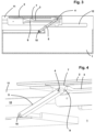
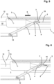
Figuren 1 und 2 Figur 4- eine vergrößerte perspektivische Darstellung eines Ausschnitts des Ablagefachs in geschlossener Stellung,
Figuren 5 bis 7- das Ablagefach gemäß
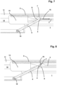
Figur 4 Figur 8- das Ablagefach in geschlossenem Zustand des Deckels, jedoch unmittelbar bei Auftreten eines Crashs und
Figur 9- das Ablagefach bei einem Crash in verriegelter Stellung des Deckels.
- figure 1
- a possible embodiment of a storage compartment with a locking device according to the invention in a perspective view and in the closed state,
- figure 2
- the storage compartment according to
figure 1 in a side view in longitudinal section, - figure 3
- the storage compartment according to
Figures 1 and 2 , in open position, - figure 4
- an enlarged perspective view of a section of the storage compartment in the closed position,
- Figures 5 to 7
- the storage compartment according to
figure 4 in a longitudinal section at the beginning of the normal (slow) opening movement of the lid, - figure 8
- the storage compartment in the closed state of the lid, but immediately when a crash occurs and
- figure 9
- the storage compartment in the event of a crash with the lid in the locked position.
Das in den Figuren dargestellte Ablagefach ist beispielsweise für die Mittelkonsole eines Kraftfahrzeuges bestimmt. Denkbar sind aber auch Ablagefächer, welche schwenkbar in den Kraftfahrzeugtüren angeordnet sind.The storage compartment shown in the figures is intended, for example, for the center console of a motor vehicle. However, storage compartments which are pivotably arranged in the motor vehicle doors are also conceivable.
Das Ablagefach weist ein in eine Aufnahme des Kraftfahrzeugs einsetzbares Gehäuse 1 auf, das mit einem Deckel 2 verschließbar ist. Der Deckel 2 ist von einer Schließ- in eine Öffnungsbewegung und umgekehrt bewegbar.The storage compartment has a
Zur Führung des Deckels 2 am Gehäuse 1 ist bei dem hier gewählten Ausführungsbeispiel beiderseits des Deckels 2 an seinen Seitenwandungen eine Kulisse 3 vorgesehen, in die ein an einem Hebel 5 angeordneter Zapfen 4 eingreift. Der Hebel 5 ist an einer gehäuseseitigen Drehachse 10 gelagert. Die Kulisse 3 dient zur Festlegung des Deckels 2 in seiner geöffneten Stellung. Die Führungsbahnen 12 auf jeder Seite des Gehäuses 1 weisen eine Kontur auf, um den Deckel 2 in Öffnungsstellung des Faches platzsparend zu überführen.In order to guide the
Zum Öffnen wird der Deckel 2 in Richtung des Pfeils 6 gegen die Kraft einer (nicht dargestellten) Feder in
Soll der Deckel 2 nun wieder in die Schließstellung überführt werden, erfolgt ein kurzes Einschieben des Deckels 2 gegen die Kraft der (nicht dargestellten) Feder in Richtung der Öffnungsstellung, was auch als Überdrücken bezeichnet wird. Hierbei gelangt der Zapfen 4 außer Eingriff mit der Verriegelungsausnehmung 14 der Herzkurve 8, so dass eine Entriegelung der Öffnungsstellung erfolgt und der Deckel 2 per Federkraft wieder in seine Schließstellung gemäß
Zum Öffnen des Deckels 2 gleitet der Zapfen 4 in der Kulisse 3, bis in Öffnungsstellung der Zapfen 4 die Verriegelungsausnehmung 14 der Herzkurve 8 hintergreift und den Deckel 2 in Öffnungsstellung hält. Diese normale oder auch langsame Öffnungsgeschwindigkeit des Deckels 2 ist in den
Um dies zu verhindern, ist bei dem hier gewählten Ausführungsbeispiel am Deckel 2 ein Anschlag 7 vorgesehen, gegen welchen der schwenkbar am Gehäuse 1 gelagerte Hebel 5 durch den Einfluss äußerer Beschleunigungskräfte in Anlagestellung gelangt. Bei einem Crash wird der Zapfen 4 über die Rampe 9 beschleunigt, so dass er, wie durch den Pfeil 16 angedeutet, auf den Anschlag 7 trifft, wodurch eine Öffnungsbewegung des Deckels 2 blockiert ist und sich der Deckel 2 in einer Blockierstellung befindet.In order to prevent this, a
Durch die Erfindung kann der durch die Push-Push-Mechanik vorgegebene Federweg, die im Normalbetrieb beim Überdrücken des Deckels 2 zum Entriegeln vorhandene Federwegreserve, ausgenutzt werden, um den Hebel 5 in die Blockierstellung des Deckels 2 zu bewegen, ohne dass sich das geschlossene Ablagefach weiter bzw. vollständig öffnet.With the invention, the spring travel specified by the push-push mechanism, the spring travel reserve available in normal operation when the
Gegebenenfalls sind das in Wirkstellung miteinander tretende Ende des Hebels 5 und der Anschlag 7 an dem Deckel 2 als miteinander wechselwirkende Rast- und Gegenrastmittel ausgebildet, so dass auch sichergestellt ist, dass der Deckel in seiner Blockierstellung verbleibt. Wenn der Fahrzeuginsasse dann den Deckel 2 in Schließstellung verschiebt, gelangen Rast- und Gegenrastmittel am Hebel 5 und Anschlag 7 außer Eingriff, so dass wieder der normale Betrieb des Ablagefaches gegeben ist.If necessary, the end of the
Selbstverständlich ist es auch möglich, die Kulisse 3 am ortsfesten Gehäuse anzuordnen, während Hebel 5 mit Zapfen 4 schwenkbar an dem Deckel 2 oder Behälter angeordnet sind.Of course, it is also possible to arrange the connecting
- 11
- GehäuseHousing
- 22
- DeckelLid
- 33
- Kulissebackdrop
- 44
- Zapfencones
- 55
- Hebellever
- 66
- Öffnungsbewegungopening movement
- 77
- Anschlag, Rastnasestop, detent
- 88th
- Herzkurveheart curve
- 99
- Schräge, Rampeslope, ramp
- 1010
- Drehachseaxis of rotation
- 1111
- SeitenwandSide wall
- 1212
- Führungsbahnguideway
- 1313
- Führungszapfenpilot
- 1414
- Verriegelungsausnehmunglocking recess
- 1515
- Bewegungsrichtung (langsam)direction of movement (slow)
- 1616
- Bewegungsrichtung (schnell)direction of movement (fast)
Claims (5)
- Locking device for a container or cover (2), in particular of motor vehicles, which container or cover is actuatable between an open position and a closed position in relation to a housing part (1), housing part (1) and container or cover (2), wherein the locking device has a slotted guide (3) and a guide pin (4) which engages into the slotted guide (3) and which is arranged on a pivotably mounted lever (5), wherein the slotted guide (3) has an inclined portion (9) by means of which the pin (4), under the influence of external acceleration forces, slides in the direction (16) of a stop (7), arranged on the container or cover (2), in order to bring the lever (5) into a position in which the movement of the container or cover (2) is blocked, characterized in that the stop (7) and the lever (5) have latching means and mating latching means which interact with one another in the blocking position.
- Locking device, housing part (1) and container or cover (2) according to Claim 1, characterized in that the slotted guide (3) with inclined portion (9) is arranged on the container or cover (12) and the lever (5) is pivotably mounted on the housing (1), or vice versa.
- Locking device, housing part (1) and container or cover (2) according to Claim 1 or 2, characterized in that the slotted guide (3) with inclined portion (9) extends on a side wall (11) of the container or cover (2) in the displacement direction (6) thereof, wherein, under the influence of the external acceleration forces, the lever (5) is subjected to a moment in the direction of the vehicle vertical axis (Z) that transfers the lever (5) into the position of abutment with the stop (7).
- Locking device, housing part (1) and container or cover (2) according to Claim 1 or 2, characterized in that the slotted guide (3) with inclined portion (9) extends on the base of the container or cover (2) in the displacement direction (6) or pivoting direction thereof, wherein, under the influence of the external acceleration forces, the lever (5) is subjected to a moment in the direction of the vehicle transverse axis (Y) or vehicle longitudinal axis (X) that transfers the lever (5) into the position of abutment with the stop (7).
- Locking device, housing part (1) and container or cover (2) according to one of the preceding claims, characterized in that a push-push mechanism for the container or cover (2) actuatable between the open position and the closed position in relation to the housing (1) is provided, wherein the container or cover (2) is held in a latching position counter to the force of a spring element.
Applications Claiming Priority (1)
| Application Number | Priority Date | Filing Date | Title |
|---|---|---|---|
| PCT/EP2020/073171 WO2022037769A1 (en) | 2020-08-19 | 2020-08-19 | Locking device for a container or lid, in particular of motor vehicles, which can be actuated between a closed and open position |
Publications (2)
| Publication Number | Publication Date |
|---|---|
| EP3990727A1 EP3990727A1 (en) | 2022-05-04 |
| EP3990727B1 true EP3990727B1 (en) | 2023-05-03 |
Family
ID=72178523
Family Applications (1)
| Application Number | Title | Priority Date | Filing Date |
|---|---|---|---|
| EP20760431.5A Active EP3990727B1 (en) | 2020-08-19 | 2020-08-19 | Locking device for a container or lid, in particular of motor vehicles, which can be actuated between a closed and open position |
Country Status (5)
| Country | Link |
|---|---|
| US (1) | US20230279701A1 (en) |
| EP (1) | EP3990727B1 (en) |
| CN (1) | CN115956155A (en) |
| MX (1) | MX2023001922A (en) |
| WO (1) | WO2022037769A1 (en) |
Citations (1)
| Publication number | Priority date | Publication date | Assignee | Title |
|---|---|---|---|---|
| US7959202B2 (en) * | 2008-05-07 | 2011-06-14 | Kia Motors Corporation | Vehicle tray having an open-prevention mechanism |
Family Cites Families (16)
| Publication number | Priority date | Publication date | Assignee | Title |
|---|---|---|---|---|
| DE4427769A1 (en) | 1994-08-05 | 1996-02-08 | Winfried H Kasper | Connector socket for low-voltage halogen light |
| DE9412661U1 (en) * | 1994-08-05 | 1994-10-06 | Sidler GmbH & Co, 72072 Tübingen | Locking device |
| DE19835364C2 (en) | 1998-08-05 | 2000-06-08 | Fischer Artur Werke Gmbh | Device for installation in a motor vehicle with a pull-out part |
| JP4462768B2 (en) * | 2001-01-19 | 2010-05-12 | 株式会社ニフコ | Locking device with safety function and storage device for vehicle |
| DE10120435A1 (en) | 2001-04-26 | 2002-10-31 | Fischer Artur Werke Gmbh | Push-push locking mechanism |
| US7793995B2 (en) * | 2006-07-27 | 2010-09-14 | Illinois Tool Works Inc. | Push/push latch |
| JP4980042B2 (en) * | 2006-12-21 | 2012-07-18 | カルソニックカンセイ株式会社 | Cover lock structure for vehicle storage box |
| KR100921299B1 (en) * | 2008-06-30 | 2009-10-09 | 현대자동차주식회사 | Apparatus for preventing from opening of tray |
| DE202010006291U1 (en) * | 2010-04-30 | 2011-09-23 | Minda Ktsn Plastic Solutions Gmbh & Co.Kg | locking device |
| DE102010050800A1 (en) | 2010-11-09 | 2012-05-10 | Audi Ag | Locking device for e.g. ashtray of motor car, has inertia-controlled locking bolt transferred under influence of external acceleration forces in pivot direction of box or cover in position in which movement of curve latch is blocked |
| DE112012002767T5 (en) * | 2011-08-09 | 2014-04-17 | Illinois Tool Works Inc. | Push / push locking |
| JP5785133B2 (en) * | 2012-06-04 | 2015-09-24 | 本田技研工業株式会社 | Safety device and case with lid using safety device |
| WO2019010086A1 (en) * | 2017-07-07 | 2019-01-10 | Shanghai Yanfeng Jinqiao Automotive Trim Systems Co. Ltd. | Vehicle interior component |
| US10696204B2 (en) * | 2018-10-31 | 2020-06-30 | GM Global Technology Operations LLC | Inertial latch |
| US11885171B2 (en) * | 2018-12-04 | 2024-01-30 | Shanghai Yanfeng Jinqiao Automotive Trim Systems Co. Ltd. | Vehicle interior component |
| US20200408005A1 (en) * | 2019-06-27 | 2020-12-31 | Ford Global Technologies, Llc | Bidirectional inertia latch for vehicle interior components |
-
2020
- 2020-08-19 MX MX2023001922A patent/MX2023001922A/en unknown
- 2020-08-19 WO PCT/EP2020/073171 patent/WO2022037769A1/en unknown
- 2020-08-19 CN CN202080103172.5A patent/CN115956155A/en active Pending
- 2020-08-19 US US18/007,385 patent/US20230279701A1/en active Pending
- 2020-08-19 EP EP20760431.5A patent/EP3990727B1/en active Active
Patent Citations (1)
| Publication number | Priority date | Publication date | Assignee | Title |
|---|---|---|---|---|
| US7959202B2 (en) * | 2008-05-07 | 2011-06-14 | Kia Motors Corporation | Vehicle tray having an open-prevention mechanism |
Also Published As
| Publication number | Publication date |
|---|---|
| US20230279701A1 (en) | 2023-09-07 |
| CN115956155A (en) | 2023-04-11 |
| WO2022037769A1 (en) | 2022-02-24 |
| MX2023001922A (en) | 2023-06-01 |
| EP3990727A1 (en) | 2022-05-04 |
Similar Documents
| Publication | Publication Date | Title |
|---|---|---|
| DE19835364C2 (en) | Device for installation in a motor vehicle with a pull-out part | |
| EP1926633B1 (en) | Storage compartment for a motor vehicle | |
| DE4130847C2 (en) | Closure cap for closing a storage compartment in the interior of a motor vehicle | |
| EP1786649B1 (en) | Belt guiding element for child safety system | |
| DE102008018321A1 (en) | Center console for a motor vehicle | |
| DE102008006980A1 (en) | Vehicle seat assembly | |
| DE102010050800A1 (en) | Locking device for e.g. ashtray of motor car, has inertia-controlled locking bolt transferred under influence of external acceleration forces in pivot direction of box or cover in position in which movement of curve latch is blocked | |
| DE102005027379B4 (en) | Locking device for a cover on a storage compartment in a motor vehicle | |
| DE102016220430A1 (en) | Inertia locking device for a release cable assembly | |
| DE102015114788A1 (en) | Container with a safety locking mechanism for a vehicle | |
| DE10009291B4 (en) | Armrest with storage compartment and lockable lid | |
| EP3990727B1 (en) | Locking device for a container or lid, in particular of motor vehicles, which can be actuated between a closed and open position | |
| EP1660743A1 (en) | Safety locking device for a container in a vehicle | |
| EP2129550B1 (en) | Loading flap for a vehicle seat | |
| DE102007031591A1 (en) | Luggage space base arrangement passenger car designed as a combined motor vehicle, has protective base provided below the luggage space, which is to be open completely in loading area placed in the loading space | |
| EP3862269B1 (en) | Storage compartment for an aircraft and aircraft having the storage compartment | |
| WO2003104591A1 (en) | Safety locking device for a container in a vehicle | |
| DE102010023731A1 (en) | Locking device for vehicle door in motor car, has pivotable component comprising mass body that is operatively connected with locking unit for deflection of mass body, where locking unit blocks movement of pivotable component | |
| EP2072717A1 (en) | Paddle-type handle unit, in particular for a depositing/storage compartment of a motor vehicle | |
| EP1681198B1 (en) | Device for allowing access to a closed space inside an automotive vehicle | |
| DE102023104395B4 (en) | Locking device for a cover that can be actuated between an open and closed position relative to a housing part, in particular of motor vehicles, and method for locking and unlocking a cover that closes a housing part | |
| EP3266964B1 (en) | Arrangement for preventing the spontaneous opening of a vehicle door or flap and vehicle having such an arrangement | |
| DE102010017230A1 (en) | Door handle arrangement for motor vehicle, has handle, which is moved from resting position to operating position for opening door and locking lever, which is moved between resting position and locked position | |
| DE102010021050B4 (en) | Crash protection for a vehicle component | |
| DE102004063119B4 (en) | safety lock |
Legal Events
| Date | Code | Title | Description |
|---|---|---|---|
| STAA | Information on the status of an ep patent application or granted ep patent |
Free format text: STATUS: UNKNOWN |
|
| STAA | Information on the status of an ep patent application or granted ep patent |
Free format text: STATUS: THE INTERNATIONAL PUBLICATION HAS BEEN MADE |
|
| PUAI | Public reference made under article 153(3) epc to a published international application that has entered the european phase |
Free format text: ORIGINAL CODE: 0009012 |
|
| STAA | Information on the status of an ep patent application or granted ep patent |
Free format text: STATUS: EXAMINATION IS IN PROGRESS |
|
| 17P | Request for examination filed |
Effective date: 20220127 |
|
| AK | Designated contracting states |
Kind code of ref document: A1 Designated state(s): AL AT BE BG CH CY CZ DE DK EE ES FI FR GB GR HR HU IE IS IT LI LT LU LV MC MK MT NL NO PL PT RO RS SE SI SK SM TR |
|
| GRAP | Despatch of communication of intention to grant a patent |
Free format text: ORIGINAL CODE: EPIDOSNIGR1 |
|
| STAA | Information on the status of an ep patent application or granted ep patent |
Free format text: STATUS: GRANT OF PATENT IS INTENDED |
|
| DAV | Request for validation of the european patent (deleted) | ||
| DAX | Request for extension of the european patent (deleted) | ||
| INTG | Intention to grant announced |
Effective date: 20230120 |
|
| GRAS | Grant fee paid |
Free format text: ORIGINAL CODE: EPIDOSNIGR3 |
|
| GRAA | (expected) grant |
Free format text: ORIGINAL CODE: 0009210 |
|
| STAA | Information on the status of an ep patent application or granted ep patent |
Free format text: STATUS: THE PATENT HAS BEEN GRANTED |
|
| AK | Designated contracting states |
Kind code of ref document: B1 Designated state(s): AL AT BE BG CH CY CZ DE DK EE ES FI FR GB GR HR HU IE IS IT LI LT LU LV MC MK MT NL NO PL PT RO RS SE SI SK SM TR |
|
| REG | Reference to a national code |
Ref country code: GB Ref legal event code: FG4D Free format text: NOT ENGLISH |
|
| REG | Reference to a national code |
Ref country code: DE Ref legal event code: R096 Ref document number: 502020003196 Country of ref document: DE |
|
| REG | Reference to a national code |
Ref country code: AT Ref legal event code: REF Ref document number: 1564720 Country of ref document: AT Kind code of ref document: T Effective date: 20230515 Ref country code: CH Ref legal event code: EP |
|
| REG | Reference to a national code |
Ref country code: IE Ref legal event code: FG4D Free format text: LANGUAGE OF EP DOCUMENT: GERMAN |
|
| P01 | Opt-out of the competence of the unified patent court (upc) registered |
Effective date: 20230530 |
|
| REG | Reference to a national code |
Ref country code: LT Ref legal event code: MG9D |
|
| REG | Reference to a national code |
Ref country code: NL Ref legal event code: MP Effective date: 20230503 |
|
| PG25 | Lapsed in a contracting state [announced via postgrant information from national office to epo] |
Ref country code: SE Free format text: LAPSE BECAUSE OF FAILURE TO SUBMIT A TRANSLATION OF THE DESCRIPTION OR TO PAY THE FEE WITHIN THE PRESCRIBED TIME-LIMIT Effective date: 20230503 Ref country code: PT Free format text: LAPSE BECAUSE OF FAILURE TO SUBMIT A TRANSLATION OF THE DESCRIPTION OR TO PAY THE FEE WITHIN THE PRESCRIBED TIME-LIMIT Effective date: 20230904 Ref country code: NO Free format text: LAPSE BECAUSE OF FAILURE TO SUBMIT A TRANSLATION OF THE DESCRIPTION OR TO PAY THE FEE WITHIN THE PRESCRIBED TIME-LIMIT Effective date: 20230803 Ref country code: NL Free format text: LAPSE BECAUSE OF FAILURE TO SUBMIT A TRANSLATION OF THE DESCRIPTION OR TO PAY THE FEE WITHIN THE PRESCRIBED TIME-LIMIT Effective date: 20230503 Ref country code: ES Free format text: LAPSE BECAUSE OF FAILURE TO SUBMIT A TRANSLATION OF THE DESCRIPTION OR TO PAY THE FEE WITHIN THE PRESCRIBED TIME-LIMIT Effective date: 20230503 |
|
| PGFP | Annual fee paid to national office [announced via postgrant information from national office to epo] |
Ref country code: IT Payment date: 20230831 Year of fee payment: 4 |
|
| PG25 | Lapsed in a contracting state [announced via postgrant information from national office to epo] |
Ref country code: RS Free format text: LAPSE BECAUSE OF FAILURE TO SUBMIT A TRANSLATION OF THE DESCRIPTION OR TO PAY THE FEE WITHIN THE PRESCRIBED TIME-LIMIT Effective date: 20230503 Ref country code: PL Free format text: LAPSE BECAUSE OF FAILURE TO SUBMIT A TRANSLATION OF THE DESCRIPTION OR TO PAY THE FEE WITHIN THE PRESCRIBED TIME-LIMIT Effective date: 20230503 Ref country code: LV Free format text: LAPSE BECAUSE OF FAILURE TO SUBMIT A TRANSLATION OF THE DESCRIPTION OR TO PAY THE FEE WITHIN THE PRESCRIBED TIME-LIMIT Effective date: 20230503 Ref country code: LT Free format text: LAPSE BECAUSE OF FAILURE TO SUBMIT A TRANSLATION OF THE DESCRIPTION OR TO PAY THE FEE WITHIN THE PRESCRIBED TIME-LIMIT Effective date: 20230503 Ref country code: IS Free format text: LAPSE BECAUSE OF FAILURE TO SUBMIT A TRANSLATION OF THE DESCRIPTION OR TO PAY THE FEE WITHIN THE PRESCRIBED TIME-LIMIT Effective date: 20230903 Ref country code: HR Free format text: LAPSE BECAUSE OF FAILURE TO SUBMIT A TRANSLATION OF THE DESCRIPTION OR TO PAY THE FEE WITHIN THE PRESCRIBED TIME-LIMIT Effective date: 20230503 Ref country code: GR Free format text: LAPSE BECAUSE OF FAILURE TO SUBMIT A TRANSLATION OF THE DESCRIPTION OR TO PAY THE FEE WITHIN THE PRESCRIBED TIME-LIMIT Effective date: 20230804 |
|
| PGFP | Annual fee paid to national office [announced via postgrant information from national office to epo] |
Ref country code: FR Payment date: 20230828 Year of fee payment: 4 Ref country code: DE Payment date: 20230831 Year of fee payment: 4 |
|
| PG25 | Lapsed in a contracting state [announced via postgrant information from national office to epo] |
Ref country code: FI Free format text: LAPSE BECAUSE OF FAILURE TO SUBMIT A TRANSLATION OF THE DESCRIPTION OR TO PAY THE FEE WITHIN THE PRESCRIBED TIME-LIMIT Effective date: 20230503 |
|
| PG25 | Lapsed in a contracting state [announced via postgrant information from national office to epo] |
Ref country code: SK Free format text: LAPSE BECAUSE OF FAILURE TO SUBMIT A TRANSLATION OF THE DESCRIPTION OR TO PAY THE FEE WITHIN THE PRESCRIBED TIME-LIMIT Effective date: 20230503 |
|
| PG25 | Lapsed in a contracting state [announced via postgrant information from national office to epo] |
Ref country code: SM Free format text: LAPSE BECAUSE OF FAILURE TO SUBMIT A TRANSLATION OF THE DESCRIPTION OR TO PAY THE FEE WITHIN THE PRESCRIBED TIME-LIMIT Effective date: 20230503 Ref country code: SK Free format text: LAPSE BECAUSE OF FAILURE TO SUBMIT A TRANSLATION OF THE DESCRIPTION OR TO PAY THE FEE WITHIN THE PRESCRIBED TIME-LIMIT Effective date: 20230503 Ref country code: RO Free format text: LAPSE BECAUSE OF FAILURE TO SUBMIT A TRANSLATION OF THE DESCRIPTION OR TO PAY THE FEE WITHIN THE PRESCRIBED TIME-LIMIT Effective date: 20230503 Ref country code: EE Free format text: LAPSE BECAUSE OF FAILURE TO SUBMIT A TRANSLATION OF THE DESCRIPTION OR TO PAY THE FEE WITHIN THE PRESCRIBED TIME-LIMIT Effective date: 20230503 Ref country code: DK Free format text: LAPSE BECAUSE OF FAILURE TO SUBMIT A TRANSLATION OF THE DESCRIPTION OR TO PAY THE FEE WITHIN THE PRESCRIBED TIME-LIMIT Effective date: 20230503 Ref country code: CZ Free format text: LAPSE BECAUSE OF FAILURE TO SUBMIT A TRANSLATION OF THE DESCRIPTION OR TO PAY THE FEE WITHIN THE PRESCRIBED TIME-LIMIT Effective date: 20230503 |
|
| REG | Reference to a national code |
Ref country code: DE Ref legal event code: R097 Ref document number: 502020003196 Country of ref document: DE |
|
| PLBE | No opposition filed within time limit |
Free format text: ORIGINAL CODE: 0009261 |
|
| STAA | Information on the status of an ep patent application or granted ep patent |
Free format text: STATUS: NO OPPOSITION FILED WITHIN TIME LIMIT |
|
| PG25 | Lapsed in a contracting state [announced via postgrant information from national office to epo] |
Ref country code: MC Free format text: LAPSE BECAUSE OF FAILURE TO SUBMIT A TRANSLATION OF THE DESCRIPTION OR TO PAY THE FEE WITHIN THE PRESCRIBED TIME-LIMIT Effective date: 20230503 |
|
| REG | Reference to a national code |
Ref country code: CH Ref legal event code: PL |
|
| PG25 | Lapsed in a contracting state [announced via postgrant information from national office to epo] |
Ref country code: MC Free format text: LAPSE BECAUSE OF FAILURE TO SUBMIT A TRANSLATION OF THE DESCRIPTION OR TO PAY THE FEE WITHIN THE PRESCRIBED TIME-LIMIT Effective date: 20230503 |
|
| 26N | No opposition filed |
Effective date: 20240206 |
|
| PG25 | Lapsed in a contracting state [announced via postgrant information from national office to epo] |
Ref country code: LU Free format text: LAPSE BECAUSE OF NON-PAYMENT OF DUE FEES Effective date: 20230819 |
|
| PG25 | Lapsed in a contracting state [announced via postgrant information from national office to epo] |
Ref country code: LU Free format text: LAPSE BECAUSE OF NON-PAYMENT OF DUE FEES Effective date: 20230819 Ref country code: CH Free format text: LAPSE BECAUSE OF NON-PAYMENT OF DUE FEES Effective date: 20230831 |
|
| PG25 | Lapsed in a contracting state [announced via postgrant information from national office to epo] |
Ref country code: SI Free format text: LAPSE BECAUSE OF FAILURE TO SUBMIT A TRANSLATION OF THE DESCRIPTION OR TO PAY THE FEE WITHIN THE PRESCRIBED TIME-LIMIT Effective date: 20230503 |
|
| REG | Reference to a national code |
Ref country code: BE Ref legal event code: MM Effective date: 20230831 |
|
| REG | Reference to a national code |
Ref country code: IE Ref legal event code: MM4A |
|
| PG25 | Lapsed in a contracting state [announced via postgrant information from national office to epo] |
Ref country code: SI Free format text: LAPSE BECAUSE OF FAILURE TO SUBMIT A TRANSLATION OF THE DESCRIPTION OR TO PAY THE FEE WITHIN THE PRESCRIBED TIME-LIMIT Effective date: 20230503 |
|
| PG25 | Lapsed in a contracting state [announced via postgrant information from national office to epo] |
Ref country code: IE Free format text: LAPSE BECAUSE OF NON-PAYMENT OF DUE FEES Effective date: 20230819 |
|
| PG25 | Lapsed in a contracting state [announced via postgrant information from national office to epo] |
Ref country code: IE Free format text: LAPSE BECAUSE OF NON-PAYMENT OF DUE FEES Effective date: 20230819 |
|
| PG25 | Lapsed in a contracting state [announced via postgrant information from national office to epo] |
Ref country code: BE Free format text: LAPSE BECAUSE OF NON-PAYMENT OF DUE FEES Effective date: 20230831 |