EP3990148B1 - Dispositif de séparation en forme de spirale pour dispositif de purification de fluides - Google Patents
Dispositif de séparation en forme de spirale pour dispositif de purification de fluides Download PDFInfo
- Publication number
- EP3990148B1 EP3990148B1 EP20733651.2A EP20733651A EP3990148B1 EP 3990148 B1 EP3990148 B1 EP 3990148B1 EP 20733651 A EP20733651 A EP 20733651A EP 3990148 B1 EP3990148 B1 EP 3990148B1
- Authority
- EP
- European Patent Office
- Prior art keywords
- separation device
- spiral
- concentric
- fluid
- outermost
- Prior art date
- Legal status (The legal status is an assumption and is not a legal conclusion. Google has not performed a legal analysis and makes no representation as to the accuracy of the status listed.)
- Active
Links
- 238000000926 separation method Methods 0.000 title claims description 155
- 239000012530 fluid Substances 0.000 title claims description 116
- 238000000746 purification Methods 0.000 title claims description 7
- 239000007788 liquid Substances 0.000 claims description 107
- 239000007787 solid Substances 0.000 claims description 101
- 239000007789 gas Substances 0.000 claims description 50
- 238000000034 method Methods 0.000 claims description 14
- 238000007599 discharging Methods 0.000 claims description 8
- 230000015572 biosynthetic process Effects 0.000 claims description 3
- 230000001419 dependent effect Effects 0.000 claims description 2
- XLYOFNOQVPJJNP-UHFFFAOYSA-N water Substances O XLYOFNOQVPJJNP-UHFFFAOYSA-N 0.000 description 17
- 239000002351 wastewater Substances 0.000 description 11
- 239000010802 sludge Substances 0.000 description 10
- 239000002245 particle Substances 0.000 description 8
- 238000005273 aeration Methods 0.000 description 7
- CURLTUGMZLYLDI-UHFFFAOYSA-N Carbon dioxide Chemical compound O=C=O CURLTUGMZLYLDI-UHFFFAOYSA-N 0.000 description 4
- 238000000855 fermentation Methods 0.000 description 3
- 230000004151 fermentation Effects 0.000 description 3
- 230000001788 irregular Effects 0.000 description 3
- VNWKTOKETHGBQD-UHFFFAOYSA-N methane Chemical compound C VNWKTOKETHGBQD-UHFFFAOYSA-N 0.000 description 3
- QVGXLLKOCUKJST-UHFFFAOYSA-N atomic oxygen Chemical compound [O] QVGXLLKOCUKJST-UHFFFAOYSA-N 0.000 description 2
- 229910002092 carbon dioxide Inorganic materials 0.000 description 2
- 230000003247 decreasing effect Effects 0.000 description 2
- 238000007872 degassing Methods 0.000 description 2
- 238000004519 manufacturing process Methods 0.000 description 2
- 244000005700 microbiome Species 0.000 description 2
- 229910052760 oxygen Inorganic materials 0.000 description 2
- 239000001301 oxygen Substances 0.000 description 2
- 239000002957 persistent organic pollutant Substances 0.000 description 2
- 239000001569 carbon dioxide Substances 0.000 description 1
- 230000000295 complement effect Effects 0.000 description 1
- 230000021615 conjugation Effects 0.000 description 1
- 238000006731 degradation reaction Methods 0.000 description 1
- 230000008021 deposition Effects 0.000 description 1
- 238000005516 engineering process Methods 0.000 description 1
- 229910010272 inorganic material Inorganic materials 0.000 description 1
- 239000011147 inorganic material Substances 0.000 description 1
- 239000000463 material Substances 0.000 description 1
- 238000012986 modification Methods 0.000 description 1
- 230000004048 modification Effects 0.000 description 1
- 239000011236 particulate material Substances 0.000 description 1
- 238000007789 sealing Methods 0.000 description 1
- 239000002002 slurry Substances 0.000 description 1
- 239000000758 substrate Substances 0.000 description 1
- 238000004065 wastewater treatment Methods 0.000 description 1
Images


Classifications
-
- B—PERFORMING OPERATIONS; TRANSPORTING
- B01—PHYSICAL OR CHEMICAL PROCESSES OR APPARATUS IN GENERAL
- B01D—SEPARATION
- B01D21/00—Separation of suspended solid particles from liquids by sedimentation
- B01D21/0087—Settling tanks provided with means for ensuring a special flow pattern, e.g. even inflow or outflow
-
- B—PERFORMING OPERATIONS; TRANSPORTING
- B01—PHYSICAL OR CHEMICAL PROCESSES OR APPARATUS IN GENERAL
- B01D—SEPARATION
- B01D21/00—Separation of suspended solid particles from liquids by sedimentation
- B01D21/003—Sedimentation tanks provided with a plurality of compartments separated by a partition wall
-
- B—PERFORMING OPERATIONS; TRANSPORTING
- B04—CENTRIFUGAL APPARATUS OR MACHINES FOR CARRYING-OUT PHYSICAL OR CHEMICAL PROCESSES
- B04C—APPARATUS USING FREE VORTEX FLOW, e.g. CYCLONES
- B04C5/00—Apparatus in which the axial direction of the vortex is reversed
- B04C5/08—Vortex chamber constructions
- B04C5/103—Bodies or members, e.g. bulkheads, guides, in the vortex chamber
-
- B—PERFORMING OPERATIONS; TRANSPORTING
- B01—PHYSICAL OR CHEMICAL PROCESSES OR APPARATUS IN GENERAL
- B01D—SEPARATION
- B01D19/00—Degasification of liquids
- B01D19/0042—Degasification of liquids modifying the liquid flow
-
- B—PERFORMING OPERATIONS; TRANSPORTING
- B01—PHYSICAL OR CHEMICAL PROCESSES OR APPARATUS IN GENERAL
- B01D—SEPARATION
- B01D21/00—Separation of suspended solid particles from liquids by sedimentation
- B01D21/0003—Making of sedimentation devices, structural details thereof, e.g. prefabricated parts
-
- B—PERFORMING OPERATIONS; TRANSPORTING
- B01—PHYSICAL OR CHEMICAL PROCESSES OR APPARATUS IN GENERAL
- B01D—SEPARATION
- B01D21/00—Separation of suspended solid particles from liquids by sedimentation
- B01D21/0039—Settling tanks provided with contact surfaces, e.g. baffles, particles
- B01D21/0042—Baffles or guide plates
-
- B—PERFORMING OPERATIONS; TRANSPORTING
- B01—PHYSICAL OR CHEMICAL PROCESSES OR APPARATUS IN GENERAL
- B01D—SEPARATION
- B01D21/00—Separation of suspended solid particles from liquids by sedimentation
- B01D21/24—Feed or discharge mechanisms for settling tanks
- B01D21/2444—Discharge mechanisms for the classified liquid
-
- B—PERFORMING OPERATIONS; TRANSPORTING
- B01—PHYSICAL OR CHEMICAL PROCESSES OR APPARATUS IN GENERAL
- B01D—SEPARATION
- B01D21/00—Separation of suspended solid particles from liquids by sedimentation
- B01D21/30—Control equipment
-
- B—PERFORMING OPERATIONS; TRANSPORTING
- B04—CENTRIFUGAL APPARATUS OR MACHINES FOR CARRYING-OUT PHYSICAL OR CHEMICAL PROCESSES
- B04C—APPARATUS USING FREE VORTEX FLOW, e.g. CYCLONES
- B04C5/00—Apparatus in which the axial direction of the vortex is reversed
- B04C5/14—Construction of the underflow ducting; Apex constructions; Discharge arrangements ; discharge through sidewall provided with a few slits or perforations
- B04C5/185—Dust collectors
-
- C—CHEMISTRY; METALLURGY
- C02—TREATMENT OF WATER, WASTE WATER, SEWAGE, OR SLUDGE
- C02F—TREATMENT OF WATER, WASTE WATER, SEWAGE, OR SLUDGE
- C02F3/00—Biological treatment of water, waste water, or sewage
- C02F3/28—Anaerobic digestion processes
- C02F3/2846—Anaerobic digestion processes using upflow anaerobic sludge blanket [UASB] reactors
Definitions
- the present invention relates to a separation device for a fluid purification device and to a method for separating liquid from solids and gas using the separation device, and more specifically to a separation device comprising spiral-shaped channels.
- Separation or settling devices for fluid purification devices are known from the prior art. They can be used for aerobic or anaerobic purification of fluid such as waste water.
- the waste water comprises liquid and also usually contains dissolved and not dissolved organic and/or inorganic material in the form of solids or solid particles.
- Anaerobic wastewater treatment is the biological treatment of wastewater without the use of air or elemental oxygen. Many applications are directed towards the removal of organic pollutants in waste water, slurries and sludge.
- the organic pollutants are converted by anaerobic microorganisms to a gas containing methane and carbon dioxide, known as "biogas”.
- biogas a gas containing methane and carbon dioxide
- Separation devices known in the art allow to separate the liquid, solids and gas, including biogas, constituting the fluid (waste water) from each other.
- WO 96/32177 discloses a separation device comprising a settling chamber, in which caps are disposed with their longitudinal axis at an angle with respect to the water level, such that fluid, comprising liquid, solids and gas, which is supplied at the bottom of the separation device, flows obliquely up, forced along the bottom of the caps. Gas bubbles are collected at a ridge located in the caps. Underneath the caps, a laminar flow can be realized, which promotes the deposition of solids contained in the fluid.
- WO 2010/036107 A1 shows a separation device to be used in combinations of different techniques (hybrid reactor systems) such as anaerobic filters and/or anaerobic lagoons.
- the separation device of WO 2010/036107 A1 comprises a settling chamber configured to be filled with the fluid; a liquid-discharge for discharging liquid from the settling chamber, the liquid discharge being arranged so as to be fitted close to the liquid level, a fluid inlet configured to supply the fluid into the settling chamber, a particulate material separation device and a sludge outlet for discharging fluid containing sludge.
- the fluid inlet further comprises a gas separation device to separate gas from the fluid, said gas separation device comprising channels.
- the settler devices of the art such as the ones of WO 96/32177 or WO 2010/036107 A1 , although achieving a certain separation efficiency, present several structural challenges. They require a cubical or prism structure, which can lead to an uneven distribution of fluid if used in a round reactor tank.
- the settling plates or caps need to have a specific angle which requires the separation device to have a specific size. Additionally, the large flat settler plates or caps may not be robust enough against overpressure or under pressure.
- WO 2016/089874 A1 discloses a particle settling device similar to the invention.
- a separation device which solves at least some of the problems indicated above.
- the invention provides a separation device for a fluid purification device, the separation device comprising: at least three concentric enclosures including an outermost enclosure and an innermost enclosure and defining at least two concentric cavities; a plurality of spiral-shaped channels formed in each of the at least two concentric cavities, so that fluid can flow through said plurality of spiral-shaped channels; a fluid inlet, for receiving fluid, located in an upper section of an outermost cavity among the at least two concentric cavities; a solids outlet, for discharging solids comprised in the fluid, located in a lower section of the separation device; and a liquid outlet, for discharging liquid comprised in the fluid, located in an upper section of at least one inner cavity among the at least two concentric cavities.
- the invention provides a separation device with a compact structure, comprising a plurality of concentric enclosures defining a plurality of cavities and forming, in these cavities, spiral-shaped channels to allow fluid to run there through.
- the spiral-shaped channels formed in each cavity in comparison with rectangular/squared inclined settler plates as used in the art, require a smaller projection area and provide a more robust structure, which can withstand overpressure and under pressure in a more effective way.
- the liquid can run through the spiral-like channels of the different cavities and leave the separation device through a fluid outlet located, in operation, in an upper section of at least one of the inner cavities, while the solids may leave the separation device through a solids outlet located, in operation, in a lower section of the separation device.
- upper section of the cavities can be understood as an upper half of the cavities, or an upper third, or even the top opening of the cavities.
- the concentric enclosures can also be referred to as concentric structures, bodies, frames, or the like, and they may have different shapes as long as they are concentric, that is, having a common longitudinal axis. They may for example have a tubular shape, such as a cylindrical shape defined by a circular horizontal cross-section, and they can also have an elliptic-cylindrical shape, defined by an elliptical horizontal cross-section, or they can have a polygonal shape, defined by for example a rectangular (such as square), hexagonal, or octagonal horizontal cross-section, or any other suitable shape.
- the concentric cavities can also be referred to as concentric chambers or concentric spaces, where the spiral-shaped channels are located.
- the concentric enclosures and concentric cavities can be referred to throughout the description as simply enclosures or cavities.
- the spiral-shaped channels according to the present invention may connect each concentric enclosure with the next concentric enclosure, so that the only way for the fluid to flow is through the spiral-shaped channels.
- spiral-shaped channels can be also referred to throughout the present description as channels, and the spiral-shaped walls can also be referred to as walls.
- the plurality of spiral-shaped channels in each concentric cavity extend parallel to each other so as to define one single spiral formation.
- the plurality of spiral-shaped channels preferably extend around a vertical axis, and the channels in each concentric cavity run preferably parallel and in contact with each other, so that they occupy the total space in the cavity and define a single spiral formation.
- the lower section of the separation device comprises a redirecting chamber located below the at least three concentric enclosures, the redirecting chamber being configured to allow the fluid to switch from a downward flow through the plurality of spiral-shaped channels of the outermost cavity, to an upward flow through the plurality of spiral-shaped channels of the at least one inner cavity.
- fluid flows downwards through the spiral-shaped channels.
- a bottom area of the outermost cavity that is, when it reaches a redirecting chamber which is a delimited space located below the at least three concentric enclosures, it switches direction, due to its own energy, and flows upwards through the spiral-shaped channels of the at least one inner cavity.
- the solids will fall downwards, against the fluid flow, due to their higher density, by coming into contact with the walls of the channels and sliding down.
- the walls of the channels thus function as separation plates, such as the flat and straight separation plates known in the art.
- the fluid will become cleaner as it flows upwards, and clean liquid (water) will reach the upper section of the at least one inner cavity.
- the lower section of the separation device comprises a solids collection chamber located below the at least three concentric enclosures and including the redirecting chamber, wherein the solids outlet is located in a bottom part of the solids collection chamber.
- the lower section refers to the section located below the concentric enclosures.
- the solids collection chamber collects the solids that separate from the fluid and slide down through the spiral-shaped channels of the cavities.
- An upper end of the solids collection chamber may be connected or affixed to the bottom of the outermost enclosure, thereby creating a space in the upper portion of the solids collection chamber, called the redirecting chamber, where the fluid which reaches the bottom of the outermost cavity can turn from a downward flow to an upward flow and continue to flow upwards through the spiral-shaped channels of the at least one inner cavity.
- the fluid inlet corresponds to a gas outlet.
- a gas separation phase takes place, and in the at least one inner cavity, a solids separation phase takes place, so that when the fluid reaches an upper section of the at least one inner cavity, the fluid has become liquid, such as clean water, which is now free or almost free from any solids and gas particles.
- a top of the outermost cavity is open thereby defining an outermost top opening
- the fluid inlet comprises an area formed by the outermost top opening.
- the top end of the outermost cavity may be uncovered, unclosed, and the separation device is preferably located inside the reactor with its top part at the water level or below the water level, so that the fluid in the reactor can enter the separation device from all directions, and not just from a specific location where an inlet is placed.
- the fluid inlet may thus be defined as the total area defined by the open top end of the outermost cavity, also called outermost top opening. Allowing the fluid to enter the separation device from all directions has the advantage of improving the flow distribution and simplifying the system design, as no account has to be taken of a specific position where an inlet is to be placed.
- the separation device further comprises a delimiting structure for separating the outermost top opening from at least one inner top opening, also called the top opening of the at least one inner cavity.
- This delimiting structure ensures that the outermost top opening, which may form the fluid inlet (and may also form the gas outlet), is separated from the opening of the at least one inner cavity, so that the fluid entering through the fluid inlet and the clean liquid leaving through the liquid outlet do not come into contact with each other.
- the delimiting structure comprises a delimiting enclosure located above and in contact with a second outermost concentric enclosure, and the at least one inner top opening is confined by the delimiting enclosure and the innermost enclosure, thereby forming a liquid collection section.
- the liquid collection section is a section for collecting liquid (almost) free of solids and gas, such as clean water.
- the liquid collection section may be placed above the concentric enclosures, being delimited by the delimiting enclosure and the innermost enclosure, and the liquid flowing upwards through the spiral-shaped channels of the least one inner cavity may reach the liquid collection section following its natural flow.
- the innermost enclosure comprises at least one collection opening in an upper section thereof to allow liquid in the liquid collection section to enter an internal chamber
- the separation device further comprises at least one liquid collection pipe protruding from the innermost enclosure towards the outside of the separation device, so as to collect the liquid in the internal chamber.
- the innermost enclosure may be higher than the other enclosures, or an additional enclosure may be attached to the top of the innermost enclosure, so that the part of the innermost enclosure that extends beyond the height of the other concentric enclosures is considered the upper section.
- This upper section may confine the liquid collection section, and the at least one collection opening is preferably located in this section so that liquid from the liquid collection section can enter the internal chamber.
- the liquid collection section comprises at least one division element, so as to divide the liquid collection section into at least two compartments, and the innermost enclosure comprises at least one collection opening for each of the at least two compartments.
- the division elements may comprise at least one division wall which extends from the innermost enclosure radially towards the delimiting enclosure and contacts it, thereby dividing the liquid collection section into at least two compartments, preferably into four compartments.
- the separation device comprises a compartment control mechanism to close at least one of the collection openings thereby stopping liquid from leaving said at least one compartment.
- This compartment control mechanism allows to control velocity at which clean water leaves the separation device, as it allows to close the collection opening of one or more compartments.
- the plurality of spiral-shaped channels are defined by spiral-shaped walls which have an inner region and an outer region with respect to a vertical cross-section of the concentric structure, wherein the spiral-shaped walls are curved upwards from the inner region towards the outer region, or curved downwards from the inner region towards the outer region.
- the plurality of spiral-shaped channels may be defined by spiral-shaped walls comprising an upper end, located at the top of the enclosure, and a lower end, located at the bottom of the enclosure, wherein the fluid flowing through the channels flows from the upper end to the lower end, or from the lower end to the upper end.
- Each wall also comprises two surfaces, a front surface and a back surface, wherein the front surface is the surface which the solid particles mostly contact and through which they slide down.
- a vertical cross-section (as will be seen clearly from the drawings), there is an inner region of the wall extending close to and including the inner edge of the wall.
- the spiral-shaped walls may connect one enclosure to the next concentric enclosure.
- a horizontal cross section of each wall defines a line which radially extends towards the centre of the concentric enclosures.
- the walls may have a flat surface running from the upper end to the lower end.
- the walls are arranged such that a horizontal cross section of each wall does not extend radially towards the centre, but has a specific inclination angle with respect to said direction.
- the wall surfaces running from the upper end to the lower end are not flat, but are either curved downwards from the inner region towards the outer region, forming an arched or concave-like shape, or curved upwards from the inner region towards the outer region, thereby forming an arched or convex-like shape.
- the plurality of spiral-shaped walls of the outermost cavity are curved downwards from the inner region towards the outer region, and the plurality of spiral-shaped walls of the at least one inner cavity are curved upwards from the inner region towards the outer region.
- a distance between each concentric enclosure and the next enclosure is between 25 millimetres and 800 millimetres, preferably between 50 millimetres and 800 millimetres, more preferably between 50 millimetres and 500 millimetres, more preferably between 50 millimetres and 200 millimetres.
- a distance of between 25 millimetres and 200 millimetres, preferably between 25 millimetres and 100 millimetres is also preferred.
- the at least three concentric enclosures correspond to at least three concentric tubes and the at least two concentric cavities correspond to at least two concentric rings.
- the enclosures have a tubular shape, such as a cylindrical shape defined by a circular horizontal cross-section.
- the cavities defined therewith have ring shapes. This allows the separation device to be fit in a round reactor tank and to provide an even fluid distribution, which cannot be achieved with separation devices with a rectangular horizontal cross-section. Additionally, a cylindrical shape combined with the spiral-shaped channels, provides a much stiffer structure of the separation device, and it allows to reduce the thickness of the walls forming the channels, because they are no longer long and straight.
- the separation device comprises at least four concentric enclosures defining at least three concentric cavities.
- This structure provides one outermost cavity where the fluid may flow downwards, and at least two inner cavities for the fluid to flow upwards.
- the outermost enclosure has a larger diameter and therefore can be provided with more channels than the inner cavities, thereby carrying more fluid.
- the channels of the inner cavities can have more suitable dimensions and the system can provide better performance.
- the solids collection chamber has a hollow inverted conical shape. If the concentric enclosures have a cylindrical shape, the solids collection chamber may have a conical shape such that the base of the cone is open and the circumferential edge is connected to the outermost cylinder.
- the separation device further comprises an aeration device located at an outside part of a lower half of the solids collection chamber, so as to supply gas (biogas or air) from underneath the separation device.
- gas biogas or air
- the plurality of spiral-shaped channels are defined by spiral-shaped walls with an irregular surface.
- the surface of the walls may be smooth, with no rugosity.
- the surface of the walls may also be irregular, uneven or corrugated. This may improve the gas separation.
- the invention provides a method of separating a fluid containing liquid, gas and solids, the method being performed by a separation device comprising at least three concentric enclosures including an outermost enclosure and an innermost enclosure, and defining at least two concentric cavities; a plurality spiral-shaped channels formed in each of the at least two concentric channels, the method comprising the steps of: receiving fluid through an upper section of an outermost cavity among the at least two concentric cavities; allowing the fluid to flow downwards through the plurality of spiral-shaped channels of the outermost cavity; when the fluid reaches a redirecting chamber located below the outermost cavity, allowing the fluid to switch from a downward flow through the plurality of spiral-shaped channels of the outermost cavity to an upward flow through the plurality of spiral-shaped channels of at least one inner cavity and, when reaching an upper section of the at least one inner cavity converted into liquid, allowing the liquid to leave the separation device; and allowing solids to move downwards through the plurality of spiral-shaped channels of the outermost cavity and through the plurality
- the method further comprises, while the fluid flows downwards through the plurality of spiral-shaped channels of the outermost cavity, allowing gas to move upwards and leave the separation device through the upper section of the outermost cavity.
- receiving fluid through the upper section of the outermost cavity comprises receiving fluid thorough a total area of an outermost top opening.
- allowing the liquid to leave the separation device through an upper section comprises allowing the liquid to reach a liquid collection section located above the at least three concentric enclosures.
- the method further comprises allowing the liquid in the liquid collection section to enter an internal chamber in an innermost cavity through at least one collection opening, and to leave the separation device through at least one liquid collection pipe connected to the innermost enclosure.
- allowing the solids to leave the separation device through a lower section of the separation device comprises allowing the solids to move downwards towards a solids collection chamber located below the at least three concentric enclosures.
- the method further comprises supplying gas from underneath the separation device through an aeration device located at an outside part of a lower half of the solids collection chamber.
- the plurality of spiral-shaped channels are defined by a plurality of spiral-shaped walls, respectively, wherein each spiral-shaped wall comprises an inner region and an outer region, and the method further comprises, in the outermost cavity, directing the solids comprised in the fluid flowing downwards towards the outer region of the spiral-shaped walls and, in the at least one inner cavity, directing the solids comprised in the fluid flowing upwards towards the inner region of the spiral-shaped walls.
- the liquid collection section is divided into at least two compartments, and the method further comprises controlling the liquid collection section to allow to close at least one compartment thereby stopping liquid from leaving said compartment.
- An application of a purification process using a separation device according to the invention comprises a reactor tank.
- Examples are aerobic, anaerobic or anoxic reactors.
- Anaerobic granular sludge bed technology refers to a reactor concept or purifier for the anaerobic treatment of wastewater.
- the top part, preferably the top edge, or the top surface, of the separation device of the present invention is located at the water level in an aerated reactor tank, so that the remaining parts of the separation device are located below the water level, since in such tank the density difference between outside the separation device (aerated) and inside the separation device (not aerated) will create a fluid flow through the separation device which will return settled solids or solid particles from the separation device back to the same or another reactor tank within the fluid separation device.
- the separation device can also be located completely below the water level or even at the bottom of the reactor.
- a reactor such as an Upflow Anaerobic Sludge Blanket (UASB) or expanded granular sludge bed (EGSB), or an aerobic reactor, according to the invention, comprises a tank having a fermentation chamber. Waste water is distributed into the tank, in an embodiment, at appropriately spaced inlets. The waste water passes upwards through a(n anaerobic) sludge bed where microorganisms in the sludge come into contact with waste water substrates.
- the resulting anaerobic degradation process in the fermentation chamber is responsible for the production of gas (e.g. biogas containing CH4 and CO2).
- gas e.g. biogas containing CH4 and CO2
- the upward motion of released gas bubbles causes hydraulic turbulence that provides reactor mixing without any mechanical parts.
- the fluid is continuously in motion in the fermentation chamber due to gas flows that find their way upwards through the fluid towards the liquid level.
- the water phase is separated from sludge solids and gas in a three-phase separator (also known the gas-liquid-solids separator), settling device or separation device, which is the object of the present invention.
- a three-phase separator also known the gas-liquid-solids separator
- settling device or separation device, which is the object of the present invention.
- a vertical cross-section should be understood as a cross-section made along a longitudinal plane including a longitudinal axis (represented by X in at least some of the figures), and a horizontal cross-section should be understood as a cross-section made along the transversal plane including a transversal axis (represented as Y in at least some of the figures).
- X longitudinal axis
- Y transversal axis
- Fig. 1A illustrates a vertical cross-section of a separation device according to an embodiment of the present invention.
- Fig. 1B illustrates a horizontal cross-section of a separation device according to an embodiment of the present invention.
- the separation device 1 according to Fig. 1A and Fig. 1B comprises a concentric structure comprising at least three concentric enclosures, among which there is an outermost enclosure 10 and an innermost enclosure 12.
- the at least three concentric enclosures define at least two concentric cavities including an outermost cavity 11 and one or more inner cavities 13.
- the concentric enclosures correspond to concentric tubes, more specifically concentric cylinders, having a circular horizontal cross-section, and the cavities correspond to rings.
- the concentric enclosures can have a polygonal shape, such as by being defined by a rectangular (even square) horizontal cross-section, or an hexagonal, or an octagonal horizontal cross-section, or any other suitable shape.
- Fig. 1A and Fig. 1B shows four concentric enclosures defining three concentric cavities.
- This settling section is thus divided into two cavities.
- This configuration is advantageous because the length A of a circular sector defining the spiral-shaped channels 14, in the case of the inner cavity 13, can otherwise be too small if only one inner cavity is used.
- the number of spiral-shaped channels 14 of each inner cavity can be decreased while keeping a sufficient length for A.
- the angle of the spiral-shaped channels 14 with respect to the vertical plane is smallest for the outermost cavity and increases towards the inner cavities. If only one inner cavity is used, this angle will be too steep at the inner cavity.
- the angle of the channels 14 in the inner cavities 13 i.e. the pitch of the spiral-shaped channels
- the distance B represents the width of a concentric cavity, which is the same or substantially the same as the width of a channel 14.
- the distance B can have a value of between 25 millimetres and 800 millimetres, preferably between 50 millimetres and 800 millimetres, more preferably between 50 millimetres and 500 millimetres, and even more preferably between 50 millimetres and 200 millimetres.
- a distance of between 25 millimetres and 200 millimetres, preferably between 25 millimetres and 100 millimetres is also preferred.
- the distance B is smaller for the outermost cavity 11 than for the second outermost cavity, or middle cavity, which is at the same time smaller than the distance B for the innermost cavity.
- the values of A and B, for the channels in the outermost cavity 11, are determined so that their proportion and the size of the channels allows the gas to move up and leave the device.
- the values of A and B for the inner cavities 13, on the other hand, are determined so that their proportions and the size of the channels allows the solids to move down against the liquid flow, and therefore it depends on the fluid characteristics.
- the pressure drop in both inner cavities 13 must be equal.
- the pressure drop is defined as the difference in total pressure between two points of a fluid carrying network, and a pressure drop occurs when frictional forces, caused by the resistance to flow, act on a fluid as it flows through the tube.
- the pressure drop depends on a friction coefficient, on the density of the water, on the length of the spiral-shaped channels 14 from the top end to the bottom end, which is the length of the path the fluid has to traverse in the channels 14, on the hydraulic diameter of the channels 14, and on the velocity of the fluid.
- the number of channels, the pitch of the spiral-shaped channels and the diameters of the sections can be chosen in such a way, that the velocity in both sections is equal.
- An embodiment with three concentric enclosures defining two concentric cavities is also possible, and also an embodiment comprising more than four concentric enclosures defining more than three concentric cavities.
- the separation device 1 further comprises a fluid inlet 15, which is located in an upper section of the outermost cavity 11.
- Said upper section is preferably an upper half or an upper third, and more preferably the fluid inlet 15 is formed in a top of the outermost cavity 11, which is preferably not covered thereby defining an outermost top opening, so that the fluid inlet 15 comprises an area formed by the outermost top opening.
- the fluid in the reactor tank where the separation device is located can enter the separation device from all directions, and not just from a specific location at which an inlet is placed.
- the fluid inlet 15 may also act as a gas outlet. That is, as the fluid flows downwards through the spiral-shaped channels 14 of the outermost cavity 11, gas particles separate from the fluid and move upwards, leaving the separation device through the gas outlet (fluid inlet).
- a gas collection system including pipes can be used to collect the gas, or the gas may simply rise and leave the separation device 1.
- a solids collection chamber 20 may be located, connected or affixed to the bottom end of the outermost enclosure 10 and defining a chamber, called a redirecting chamber, where the fluid, after reaching the bottom of the spiral-shaped channels 14 of the outermost cavity 11, can turn from a downward flow to an upward flow, using the own energy of the fluid. The fluid then may flow upwards through the spiral-shaped channels 14 of the at least one inner cavity 13, in this embodiment two inner cavities.
- solid particles may separate from the liquid because of their higher density and because of the friction with the surface of the channels 14, and fall down, settling at the bottom of the solids collection chamber 20 to then leave the solids collection chamber 20 through a solids outlet 22 located preferably at the bottom of the solids collection chamber.
- the solids collection chamber 20 can have several shapes. However, in the embodiment of Fig. 1A and Fig. 1B , it has a conical shape, to improve its attachment with the concentric structure, which can be achieved by attaching or engaging the circumferential edge of the cone base to the bottom of the outermost enclosure 10. However, it should be noted that other shapes are possible as long as the solids collection chamber 20 allows the solids to be collected and removed from the separation device 1, and as long as there is a space allowing the fluid to exit the channels 14 of the outermost cavity 11 and enter the channels 14 of the at least one inner cavity 13.
- Fig. 1A and Fig. 1B also show a liquid outlet which comprises a liquid collection section 30 and at least one liquid collection pipe 36.
- the liquid collection section 30 may be enclosed or delimited by the innermost enclosure 12 and a delimiting structure which separates the top opening of the outermost cavity 11 from the top opening of the inner cavities 13.
- This delimiting structure is preferably a delimiting enclosure 31, which has a similar shape as the other concentric enclosures, and is placed with one end attached to the top of the second outermost enclosure.
- This delimiting enclosure can also be clearly seen in Fig. 4 which will be described in more detail below.
- the innermost enclosure 12 may be solid, or (partially) hollow. If it is (partially) hollow, it may define an internal chamber 35 which can contribute to the collection of liquid (clean water).
- the innermost enclosure 12 may have a height H1 larger than the height H of the other concentric enclosures, or, instead, an additional enclosure can be attached to the top of the innermost enclosure providing a larger height defining an upper section, so that said upper section (of height H2) can act as a wall delimiting the liquid collection section 30.
- at least one collection opening 34 visible in Fig. 4
- the liquid can then be discharged by means of at least one liquid collection pipe 36 which is connected to the innermost enclosure 12 and collects liquid stored therein.
- the liquid collection section can be divided in compartments.
- the spiral-shaped channels may be defined by spiral-shaped walls connecting each enclosure with the next enclosure, as is the case of Fig. 1A and Fig. 1B .
- the spiral-shaped channels may also be defined by spiral-shaped hollow members or hollow arms having a polygonal horizontal cross-section, such as rectangular (square), or other type of polygonal, circular or elliptical horizontal cross-section, said hollow arms being fit in the cavities and being attached to each other and to the enclosures defining the cavities.
- the spiral-shaped channels are defined by walls connecting each enclosure with the next one.
- the spiral-shaped channels are defined by hollow arms with a square or rectangular horizontal cross-section.
- the plurality of spiral-shaped channels 14 are defined by spiral-shaped walls 19, which have an upper end and a lower end and connect one enclosure to the next concentric enclosure.
- These spiral-shaped walls 19 have a front surface (or top surface), through which the fluid flows, that is, the surface which the solids mostly contact, and a back surface (or bottom surface).
- the spiral-shaped walls have also an inner region 17, with respect to a vertical cross-section, extending along the whole length of the wall close to and including the inner edge, and an outer region 18 which similarly extends close to and including an outer edge.
- each wall 19 defines a line which extends radially towards the centre of the concentric enclosures, said line having substantially the same length as the width (distance B) of the concentric cavity where it is located.
- the walls have a flat surface running from the upper end to the lower end.
- Fig. 2 depicts a vertical cross-section of a separation device according to an embodiment of the present invention when located inside a reactor tank.
- the separation device 1 is located inside of a reactor tank, which can be an aerobic or an anaerobic reactor.
- the separation device 1 of the embodiment of Fig. 2 is located in an upper part of the reactor 2, such as in an upper half, and with its top part at the fluid level 3 or below the fluid level 3.
- the separation device 1 can also be placed in other locations within the reactor, and the working principle will be the same.
- the separation device 1 may be located close to or at the bottom of the reactor. A method of separating liquid, solids and gas in a fluid will be described in relation with Fig. 2 .
- step 1) fluid such as waste water comprising liquid, solids and gas, is received by the separation device 1 through fluid inlet 15 located in an upper section of the outermost cavity 11, which in this case corresponds to the whole top opening of the outermost cavity 11.
- step 2) allowed to flow downwards through the spiral-shaped channels 14, (most of the) gas comprised in the fluid separates from the fluid, partly due to the friction of the fluid with the surface of the walls defining the channels, which can be smooth or irregular, and the gas moves upwards, leaving the separation device through a gas outlet which corresponds to the fluid inlet 15.
- step 3 after the fluid reaches a bottom area of the outermost cavity 11, it reaches a redirecting chamber which is a part of the solids collection chamber 20, and which is a delimited space where the fluid is allowed to switch from a downward flow to an upward flow and to flow upwards through the plurality of spiral-shaped channels 14 of at least one inner cavity 13.
- the liquid is allowed to leave the separation device.
- Step 4) corresponds to the step of allowing solids, which moved downwards through the plurality of spiral-shaped channels 14 of the outermost cavity 11, and which also moved downwards through the plurality of spiral-shaped channels 14 of the at least one inner cavity 13, to leave the separation device 1 through a lower section of the separation device, preferably through a solids outlet 22 located at the bottom of the solids collection chamber 20.
- the liquid (clean water) that has reached the upper section may enter the liquid collection section 30, from where the liquid may access the internal chamber 35 of the innermost enclosure 12 via, for example, at least one collecting opening 34.
- a liquid collection pipe 36 or any other liquid discharging element can be connected to the innermost enclosure 12 and remove, in step 6), the liquid stored therein. If the internal chamber 35 is not present, the liquid in the liquid collection section 30 can be directly connected by at least one pipe.
- Fig. 3 shows a perspective view of a part of the separation device according to an embodiment of the present invention.
- Fig. 3 an upper part of the spiral-shaped channels 14 in the different concentric cavities can be seen.
- the horizontal cross-section of the spiral-shaped walls 19 defining the spiral-shaped channels 14 can be seen, which extend radially towards the center of the concentric enclosures.
- the distance B represents the width of a concentric cavity, which is the same or substantially the same as the width of a spiral-shaped channel 14 formed in said cavity. As seen above in relation with Fig. 1A and 1B , the distance B can have different values.
- Fig. 4 shows another perspective view of a part of the separation device according to an embodiment of the present invention.
- Fig. 4 focuses on the liquid collection section 30 located above the concentric enclosures.
- This liquid collection section 30 may have different elements than those shown in Fig. 4 , as the configuration shown in Fig. 4 is merely an example and other configurations are possible.
- the embodiment of Fig. 4 shows a delimiting enclosure 31 affixed to the top of the second outermost enclosure, and having a height which can be substantially the same as the additional height H2 (see Fig. 1A ) of the innermost enclosure 12.
- the height of the delimiting enclosure 31 may also be larger than the height H2, to ensure that no liquid in the liquid collection section 30 or inside the internal chamber 35 overflows and leaves the separation device.
- the innermost enclosure 12 comprises at least one collection opening 34 in an upper section thereof (section of height H2 that extends beyond the height of the other concentric enclosures, which can be part of the innermost enclosure or an additional enclosure attached to the top of the innermost enclosure) to allow liquid in the liquid collection section 30 to enter an internal chamber 35.
- At least one liquid collection pipe 36, or other liquid discharging means, may protrude from the innermost enclosure 12 towards the outside of the separation device 1, so as to collect the liquid from the internal chamber 35.
- Fig. 4 depicts four delimiting elements 32 which divide the liquid collection section 30 into four compartments 33.
- the delimiting elements 32 of the embodiment of Fig. 4 comprise division walls which radially extend from the innermost enclosure 12 to a position in the delimiting enclosure 31 thereby dividing the liquid collection section 30 into a plurality of compartments 33.
- the advantage of having several compartments is that one or more of these compartments can be closed.
- This mechanism allows to control the velocity of the fluid in the separation device.
- the innermost enclosure 12 may comprise a plurality of collection openings 34, so that at least one collection opening 34 connects each compartment with the internal chamber 35.
- the separation device may comprise a compartment control mechanism to close or open at least one of the collection openings 34 based on a desired velocity of liquid in separation device.
- the compartment control mechanism may comprise a cover or sealing structure which closes at least one of the collection openings 34.
- the control mechanism may be manually controlled, or may be automatically controlled by means of a sensor system..
- the delimiting elements 32 extend radially following the radial distribution of the spiral-shaped walls (as seen clearly in Fig. 1B ).
- the delimiting elements 32 may have a different shape, adapted to the distribution of the spiral-shaped walls.
- the delimiting elements 32 when the spiral-shaped walls do not extend radially, the delimiting elements 32 have a shape which adapts to the horizontal cross-section of the walls, so as to effectively delimit the compartments of the liquid collection section 30.
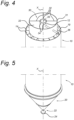
- Fig. 5 shows another perspective view of a part of the separation device according to an embodiment of the present invention.
- Fig. 5 depicts a close-up view of the solids collection chamber 20, and is an example of said solids collection chamber 20 having an inverted conical shape with its base open and with an edge region of the base being in contact with the bottom end of the outermost enclosure 10.
- the solids outlet 22 is located at a bottom part of the solids collection chamber 20.
- the solids collection chamber 20 may comprise a stopper 24 located below the solids outlet 22, configured to prevent air from entering the solids collection chamber 20 while allowing the solids to leave through the solids outlet 22.
- the stopper 24 has a conical shape, but the invention is not limited thereto.
- the separation device further comprises an aeration device located at an outside part of a lower half of the solids collection chamber, so as to supply gas (biogas or air) from underneath the separation device.
- the liquid and solids flow through the separation device is driven by the density difference of liquid, solids and gas outside the separation device, and only liquid and solids inside the separation device. This density difference is dependent on either the gas (e.g.: biogas) production, or aeration means needed to supply oxygen to the aerated reactor in which the separation device is located.
- the gas volumes generated are however not necessarily the correct gas volumes for an efficient water and sludge flow over the separation device. This can be avoided by having a dedicated aeration device for supplying either air or biogas from underneath the separator.
- the aeration device is located in the lower half of the solids collection chamber 20, on the outside of the solids collection chamber 20, in proximity to or in contact with the outside surface of the solids collection chamber 20, and above the solids outlet 22.
- the aeration device may comprise a pipe system with at least one pipe comprising at least one opening, preferably a plurality of openings, so that gas can be supplied through said openings to the reactor, thereby controlling the amount of gas generated, which controls the density difference between outside the separation device and inside the separation device, and allowing to obtain an efficient flow of liquid and solids through the separation device.
- Fig. 6A illustrates a vertical cross-section of a separation device according to an embodiment of the present invention.
- Fig. 6B illustrates a horizontal cross-section of a separation device according to an embodiment of the present invention.
- the embodiment of Fig. 6A and Fig. 6B is similar to that of Fig. 1A and Fig. 1B and the similar features will not be described again.
- spiral-shaped channels 14 of the embodiment of Fig. 6A and Fig. 6B have a different shape from those of Fig. 1A and Fig. 1B .
- the plurality of spiral-shaped channels 14 of Fig. 6A and Fig. 6B are defined by spiral-shaped walls 19 which are not flat, and their horizontal cross-section does not radially extend towards the centre of the concentric structure. Instead, the spiral-shaped walls 19 are arranged such that a horizontal cross-section of each wall 19 is inclined with respect to said direction to form a specific angle ⁇ , as seen in Fig. 6B , which will be explained in detail below.
- the spiral-shaped walls 19 are not flat, and have, with respect to a vertical cross-section as seen in Fig. 6B , either the inner region 17 curved downwards towards the outer region 18, forming a concave-like shape, or have the inner region 17 curved upwards the outer region, forming a convex-like shape.
- This implementation has the advantage that the solids comprised in the fluid will tend to move towards one region or the other of the walls 19 while the fluid is flowing downwards or upwards, thereby directing the solids towards a desired location in the separation device.
- the plurality of spiral-shaped walls 19 of the outermost cavity 11 have the inner region 17 curved downwards towards the outer region 18 so as to allow solids to move downwards closer to the outer edge, that is, to the outermost concentric enclosure 10. This allows the solids to reach the solids separation chamber 20 closer to the conical walls and therefore they can slide and settle at the bottom of the solids separation chamber 20 in a faster way.
- the plurality of spiral-shaped walls 19 of the at least one inner cavity 13 have the inner region 17 curved upwards towards the outer region 18 so as to allow solids to move downwards closer to the inner edge, that is, to the innermost concentric enclosure 12.
- the shape of the walls 19 defining the channels 14 is such that the solids tend to move towards the inner edge, towards the centre, thereby falling almost directly to the bottom of the solids collection chamber 20 going through the shortest route.
- the value of the angle ⁇ determines the radius of the curve that the spiral-shaped walls 19 define from the inner region 17 to the outer region 18.
- a larger angle ⁇ means a deeper concave or convex shape as described above. The smaller ⁇ is, the closer the cross-section of the walls is to the radius of the concentric enclosure, and the flatter the surface of the walls is.
- ⁇ has a positive value (as in the inner cavities of Fig. 6B )
- it will determine that the inner region 17 is cured upwards towards the outer region 18 (as seen in the inner cavities of Fig. 6A )
- ⁇ has a negative value (as in the outermost cavity of Fig. 6B )
- it will determine that the inner region is curved downwards towards the outer region (as seen in the outermost cavity of Fig. 6A ).
- Fig. 7 depicts a close-up view, marked as VII in Fig. 6A ) of a part of a separation device according to an embodiment of the present invention, specifically a partial vertical cross-section showing the center of the concentric enclosure in the right end of the figure.
- the plurality of spiral-shaped walls 19 of the outermost cavity 11 have, with respect to a vertical cross-section, the inner region 17 curved downwards towards the outer region 18, and the solids, represented as dark circles in the figure, tend to move downwards closer to the outermost concentric enclosure, while the gas, represented as white circles in the figure, tends to move upward in an opposite direction.
- the plurality of spiral-shaped walls 19 of the at least one inner cavity 13 two inner cavities 13 in this embodiment
- Fig. 8 shows another perspective view of a part of the separation device according to an embodiment of the present invention.
- the representation of Fig. 8 is very similar to that of Fig. 3 , however from Fig. 8 it can be seen that a horizontal cross-section of the walls 19 defining the spiral-shaped channels 14 defines an angle ⁇ with respect to the direction of the radius and thus does not follow the radial direction as in the embodiment ofFig. 3.
Landscapes
- Chemical & Material Sciences (AREA)
- Chemical Kinetics & Catalysis (AREA)
- Life Sciences & Earth Sciences (AREA)
- Microbiology (AREA)
- Biodiversity & Conservation Biology (AREA)
- Hydrology & Water Resources (AREA)
- Engineering & Computer Science (AREA)
- Environmental & Geological Engineering (AREA)
- Water Supply & Treatment (AREA)
- Organic Chemistry (AREA)
- Cyclones (AREA)
- Separating Particles In Gases By Inertia (AREA)
- Purification Treatments By Anaerobic Or Anaerobic And Aerobic Bacteria Or Animals (AREA)
Claims (15)
- Dispositif de séparation (1) pour un dispositif de purification de fluide, le dispositif de séparation comprenant :- au moins trois enceintes concentriques incluant une enceinte la plus extérieure (10) et une enceinte la plus intérieure (12) et définissant au moins deux cavités concentriques ;- une pluralité de canaux en forme de spirale (14) formés dans chacune des au moins deux cavités concentriques, de sorte qu'un fluide peut circuler à travers ladite pluralité de canaux en forme de spirale ;- une entrée de fluide (15), pour recevoir un fluide, située dans une section supérieure d'une cavité la plus extérieure (11) parmi les au moins deux cavités concentriques, l'entrée de fluide (15) correspondant à une sortie de gaz ;- une sortie de matières solides (22), pour décharger des matières solides comprises dans le fluide, située dans une section inférieure du dispositif de séparation ; et- une sortie de liquide, pour décharger un liquide compris dans le fluide, située dans une section supérieure d'au moins une cavité intérieure (13) parmi les au moins deux cavités concentriques,où la section inférieure du dispositif de séparation comprend une chambre de changement de sens située sous les au moins trois enceintes concentriques, la chambre de changement de sens étant configurée pour permettre au fluide de changer d'un flux vers le bas à travers la pluralité de canaux en forme de spirale (14) de la cavité la plus extérieure (11), à un flux vers le haut à travers la pluralité de canaux en forme de spirale (14) de l'au moins une cavité intérieure (13).
- Dispositif de séparation (1) selon la revendication 1, où la pluralité de canaux en forme de spirale (14) dans chaque cavité concentrique s'étendent parallèlement les uns aux autres afin de définir une seule formation en spirale.
- Dispositif de séparation (1) selon la revendication 2, où la section inférieure du dispositif de séparation comprend une chambre de collecte de matières solides (20) située sous les au moins trois enceintes concentriques et incluant la chambre de changement de sens, où la sortie de matières solides (22) est située dans une partie inférieure de la chambre de collecte de matières solides.
- Dispositif de séparation (1) selon l'une quelconque des revendications précédentes, où une partie supérieure de la cavité la plus extérieure est ouverte définissant ainsi une ouverture de partie supérieure la plus extérieure , et l'entrée de fluide (15) comprend une zone formée par l'ouverture de partie supérieure la plus extérieure.
- Dispositif de séparation (1) selon la revendication 4, comprenant en outre une structure de délimitation pour séparer l'ouverture de partie supérieure la plus extérieure d'au moins une ouverture de partie supérieure intérieure.
- Dispositif de séparation (1) selon la revendication 5, où la structure de délimitation comprend une enceinte de délimitation (31) située au-dessus de et en contact avec une deuxième enceinte concentrique la plus extérieure, et l'au moins une ouverture de partie supérieure intérieure est confinée par l'enceinte de délimitation et l'enceinte la plus intérieure (12), formant ainsi une section de collecte de liquide (30).
- Dispositif de séparation (1) selon la revendication 6, où l'enceinte la plus intérieure (12) comprend au moins une ouverture de collecte (34) dans une section supérieure de celle-ci pour permettre au liquide dans la section de collecte de liquide (30) d'entrer dans une chambre interne (35), et où le dispositif de séparation comprend en outre au moins un tuyau de collecte de liquide (36) saillant de l'enceinte la plus intérieure (12) vers l'extérieur du dispositif de séparation, afin de collecter le liquide dans la chambre interne (35).
- Dispositif de séparation (1) selon les revendications 6 ou 7, où la section de collecte de liquide (30) comprend au moins un élément de division (32), afin de diviser la section de collecte de liquide en au moins deux compartiments (33), et où l'enceinte la plus intérieure (12) comprend au moins une ouverture de collecte (34) pour chacun des au moins deux compartiments (33).
- Dispositif de séparation (1) selon la revendication 8, où le dispositif de séparation comprend un mécanisme de contrôle de compartiment pour fermer l'au moins une des ouvertures de collecte (34) empêchant ainsi le liquide de quitter un compartiment correspondant (33).
- Dispositif de séparation (1) selon l'une quelconque des revendications précédentes, où la pluralité de canaux en forme de spirale (14) sont définis par des parois en forme de spirale (19) qui ont une région intérieure (17) et une région extérieure (18) par rapport à une coupe transversale verticale, où les parois en forme de spirale sont incurvées vers le haut depuis la région intérieure vers la région extérieure, ou incurvées vers le bas depuis la région intérieure vers la région extérieure.
- Dispositif de séparation (1) selon la revendication 10, où la pluralité de parois en forme de spirale (19) de la cavité la plus extérieure (11) sont incurvées vers le bas depuis la région intérieure (17) vers la région extérieure (18), et la pluralité de parois en forme de spirale (19) de l'au moins une cavité intérieure (13) sont incurvées vers le haut depuis la région intérieure (17) vers la région extérieure (18).
- Dispositif de séparation (1) selon l'une quelconque des revendications précédentes, où une distance (B) entre chaque enceinte concentrique et l'enceinte suivante est entre 50 millimètres et 800 millimètres, de préférence entre 50 millimètres et 500 millimètres, plus préférentiellement entre 50 millimètres et 200 millimètres.
- Dispositif de séparation (1) selon l'une quelconque des revendications précédentes, où les au moins trois enceintes concentriques correspondent à au moins trois tubes concentriques ayant une forme cylindrique et les au moins deux cavités concentriques correspondent à au moins deux anneaux concentriques.
- Dispositif de séparation (1) selon l'une quelconque des revendications 3, et des revendication 4 à 13 lorsqu'elles dépendent de la revendication 3, où la chambre de collecte de matières solides (20) a une forme conique inversée creuse.
- Procédé de séparation d'un fluide contenant du liquide, du gaz et des matières solides, le procédé étant effectué par un dispositif de séparation (1) comprenant au moins trois enceintes concentriques incluant une enceinte la plus extérieure (10) et une enceinte la plus intérieure (12), et définissant au moins deux cavités concentriques ; une pluralité de canaux en forme de spirale (14) formés dans chacun des au moins deux canaux concentriques, le procédé comprenant les étapes de :- recevoir un fluide à travers une section supérieure d'une cavité la plus extérieure (11) parmi les au moins deux cavités concentriques ;- permettre au fluide de circuler vers le bas à travers la pluralité de canaux en forme de spirale (14) de la cavité la plus extérieure (11) et permettre au gaz contenu dans le fluide de se déplacer vers le haut à travers la pluralité de canaux en forme de spirale (14) de la cavité la plus extérieure (11) et de sortir du dispositif de séparation à travers la section supérieure de la cavité la plus extérieure (11) ;- lorsque le fluide atteint une chambre de changement de sens située sous la cavité la plus extérieure (11), permettre au fluide de changer d'un flux vers le bas à travers la pluralité de canaux en forme de spirale (14) de la cavité la plus extérieure (11), à un flux vers le haut à travers la pluralité de canaux en forme de spirale (14) d'au moins une cavité intérieure (13) et, lorsqu'il atteint une section supérieure de l'au moins une cavité intérieure converti en liquide, permettre au liquide de sortir du dispositif de séparation ; et- permettre aux matières solides de se déplacer vers le bas à travers la pluralité de canaux en forme de spirale (14) de la cavité la plus extérieure (11) et à travers la pluralité de canaux en forme de spirale (14) de l'au moins une cavité intérieure (13) et de sortir du dispositif de séparation à travers une section inférieure du dispositif de séparation.
Applications Claiming Priority (2)
| Application Number | Priority Date | Filing Date | Title |
|---|---|---|---|
| EP19182934 | 2019-06-27 | ||
| PCT/EP2020/067626 WO2020260354A1 (fr) | 2019-06-27 | 2020-06-24 | Dispositif de séparation en forme de spirale pour dispositif de purification de fluide |
Publications (2)
| Publication Number | Publication Date |
|---|---|
| EP3990148A1 EP3990148A1 (fr) | 2022-05-04 |
| EP3990148B1 true EP3990148B1 (fr) | 2023-08-09 |
Family
ID=67105901
Family Applications (1)
| Application Number | Title | Priority Date | Filing Date |
|---|---|---|---|
| EP20733651.2A Active EP3990148B1 (fr) | 2019-06-27 | 2020-06-24 | Dispositif de séparation en forme de spirale pour dispositif de purification de fluides |
Country Status (8)
| Country | Link |
|---|---|
| US (1) | US20220258183A1 (fr) |
| EP (1) | EP3990148B1 (fr) |
| JP (1) | JP2022538530A (fr) |
| KR (1) | KR20220024703A (fr) |
| CN (1) | CN114025884A (fr) |
| ES (1) | ES2963383T3 (fr) |
| PL (1) | PL3990148T3 (fr) |
| WO (1) | WO2020260354A1 (fr) |
Families Citing this family (3)
| Publication number | Priority date | Publication date | Assignee | Title |
|---|---|---|---|---|
| AU2022257615B2 (en) * | 2021-04-12 | 2023-11-23 | Supercritical Fluid Technologies, Inc. | Gas-liquid separator assembly |
| WO2023147924A1 (fr) | 2022-02-04 | 2023-08-10 | Paques I.P. B.V. | Installation de traitement microbiologique des eaux usées |
| KR102678713B1 (ko) | 2023-09-26 | 2024-06-27 | 주식회사 이음네트워크 | 로비폰 시스템을 이용한 스마트 통합 주차 관제 방법 |
Family Cites Families (20)
| Publication number | Priority date | Publication date | Assignee | Title |
|---|---|---|---|---|
| US513090A (en) * | 1894-01-23 | Dust or shavings collector | ||
| CH585062A5 (fr) * | 1974-12-03 | 1977-02-28 | Sulzer Ag | |
| US4737282A (en) * | 1984-09-10 | 1988-04-12 | Senyard Sr Corley P | Apparatus for separating sand and oil from a waste water stream |
| DE3509789A1 (de) * | 1985-03-19 | 1986-10-30 | Siegbert Dr.-Ing. 3101 Lachendorf Schulz | Zyklonabscheider mit zwei abscheideraeumen und statischen leitvorrichtungen |
| GB9313589D0 (en) * | 1993-07-01 | 1993-08-18 | Southern Water Services Ltd | Separating liquid suspensions |
| US5403473A (en) * | 1994-02-15 | 1995-04-04 | Automatic Control Technology, Inc. | Apparatus for mixing gases and liquids and separating solids using a vortex |
| NL1000100C2 (nl) | 1995-04-10 | 1996-10-11 | Pacques Bv | Bezinkinrichting voor een vloeistof, gas, en deeltjesvormig materiaal bevatten fluïdum alsmede een hiervan voorziene reinigingsinrichting en werkwijze voor het reinigen van afvalwater. |
| GB2317351A (en) * | 1996-09-19 | 1998-03-25 | Patrick Todkill | A tangential flow separator with inner settlement chamber |
| EP1588988A1 (fr) * | 2004-04-02 | 2005-10-26 | Biothane Systems International B.V. | Separateur triphase pour un reacteur uasb |
| AU2007357799B9 (en) * | 2007-08-16 | 2013-08-01 | Tata Steel Limited | Cyclone for dense medium separation |
| CN101878057A (zh) * | 2007-11-29 | 2010-11-03 | 塑料检测学会荷兰有限责任公司 | 用于分离液体混合物的液体分离装置 |
| DE202008017818U1 (de) * | 2008-08-12 | 2010-07-01 | Voith Patent Gmbh | Dreiphasen-Kaskadentrennvorrichtung |
| EP2065344A1 (fr) | 2008-09-23 | 2009-06-03 | Paques Bio Systems B.V. | Décanteur, purificateur contenant le décanteur et procédé de purification d'eau par traitement anaérobie ou aérobie |
| CN102225383B (zh) * | 2011-04-07 | 2012-08-08 | 常州大学 | 一种分离器 |
| CN102430485A (zh) * | 2011-11-07 | 2012-05-02 | 成都鑫三洋科技发展有限公司 | 一种旋流式分离器 |
| SE537139C2 (sv) * | 2012-10-09 | 2015-02-17 | Nano Control Ab | Anordning för avskiljning av partiklar från ett gasflöde |
| US20190210042A1 (en) * | 2014-07-09 | 2019-07-11 | Sudhin Biopharma | Particle setting devices |
| WO2016089874A1 (fr) * | 2014-12-01 | 2016-06-09 | Sudhin Biopharma | Dispositif de décantation de particules à rampes annulaires |
| CN205099459U (zh) * | 2015-11-03 | 2016-03-23 | 浙江环耀环境建设有限公司 | 一种高效三相分离器 |
| CN106964502B (zh) * | 2017-03-26 | 2018-11-02 | 东北石油大学 | 一种带螺旋结构的三相旋流分离器 |
-
2020
- 2020-06-24 PL PL20733651.2T patent/PL3990148T3/pl unknown
- 2020-06-24 US US17/620,130 patent/US20220258183A1/en active Pending
- 2020-06-24 ES ES20733651T patent/ES2963383T3/es active Active
- 2020-06-24 JP JP2021573939A patent/JP2022538530A/ja active Pending
- 2020-06-24 KR KR1020227001811A patent/KR20220024703A/ko unknown
- 2020-06-24 WO PCT/EP2020/067626 patent/WO2020260354A1/fr active Application Filing
- 2020-06-24 EP EP20733651.2A patent/EP3990148B1/fr active Active
- 2020-06-24 CN CN202080047065.5A patent/CN114025884A/zh active Pending
Also Published As
| Publication number | Publication date |
|---|---|
| PL3990148T3 (pl) | 2024-01-22 |
| WO2020260354A1 (fr) | 2020-12-30 |
| US20220258183A1 (en) | 2022-08-18 |
| JP2022538530A (ja) | 2022-09-05 |
| ES2963383T3 (es) | 2024-03-26 |
| CN114025884A (zh) | 2022-02-08 |
| KR20220024703A (ko) | 2022-03-03 |
| EP3990148A1 (fr) | 2022-05-04 |
Similar Documents
| Publication | Publication Date | Title |
|---|---|---|
| EP3990148B1 (fr) | Dispositif de séparation en forme de spirale pour dispositif de purification de fluides | |
| CA1155068A (fr) | Dispositif pour separer des particules liquides ou solides d'un liquide qui les renferme | |
| US4221671A (en) | Upright circular tube settler with stacked tube modules | |
| EP1265686B1 (fr) | Dispositif de filtrage a structures lamellaires servant a filtrer des liquides | |
| CN101979342B (zh) | 生物反应器 | |
| US8748167B2 (en) | Compact air purifier | |
| CA2835304C (fr) | Biofiltre pour la digestion des eaux usees | |
| RU2712581C1 (ru) | Дегазирующее устройство для анаэробного очистного устройства | |
| CN205760667U (zh) | 一种膜生物反应器及其卷式膜组件 | |
| US5204048A (en) | Method for making a bundle of helical tubes and apparatus for separating impurities from a polluted liquid | |
| CN1824613B (zh) | 多孔管式处理水流出组件及利用该组件的处理水流出装置 | |
| ES2214203T3 (es) | Dispositivo para flotacion en columna. | |
| JP4962633B2 (ja) | 生物反応器 | |
| CN210078931U (zh) | 一种波浪曲面导流规整填料 | |
| GB2114013A (en) | Liquid treatment apparatus | |
| CN219585908U (zh) | 一种ic厌氧反应器 | |
| KR102210822B1 (ko) | 부유식 디스크 필터 | |
| CN216863921U (zh) | 一种新型高效的三相分离装置 | |
| RU2242266C1 (ru) | Фильтр для очистки жидких сред | |
| JP5176384B2 (ja) | 生物反応器 | |
| SU1722537A1 (ru) | Вертикальный сепарационный фильтр | |
| KR200332741Y1 (ko) | 폴리에틸렌 여재를 사용한 다단계 수두차 여과식 하천정화 장치 | |
| WO2022075829A1 (fr) | Clarificateur/gazéificateur pour bioréacteurs de traitement d'eaux résiduelles avec de multiples types de biomasse et de biofilm | |
| CN116835797A (zh) | 一种好氧曝气沉淀一体化装置 | |
| HU182551B (hu) | Berendezés folyadékok kezelésére |
Legal Events
| Date | Code | Title | Description |
|---|---|---|---|
| STAA | Information on the status of an ep patent application or granted ep patent |
Free format text: STATUS: UNKNOWN |
|
| STAA | Information on the status of an ep patent application or granted ep patent |
Free format text: STATUS: THE INTERNATIONAL PUBLICATION HAS BEEN MADE |
|
| PUAI | Public reference made under article 153(3) epc to a published international application that has entered the european phase |
Free format text: ORIGINAL CODE: 0009012 |
|
| STAA | Information on the status of an ep patent application or granted ep patent |
Free format text: STATUS: REQUEST FOR EXAMINATION WAS MADE |
|
| 17P | Request for examination filed |
Effective date: 20220111 |
|
| AK | Designated contracting states |
Kind code of ref document: A1 Designated state(s): AL AT BE BG CH CY CZ DE DK EE ES FI FR GB GR HR HU IE IS IT LI LT LU LV MC MK MT NL NO PL PT RO RS SE SI SK SM TR |
|
| DAV | Request for validation of the european patent (deleted) | ||
| DAX | Request for extension of the european patent (deleted) | ||
| REG | Reference to a national code |
Ref country code: DE Ref legal event code: R079 Ref document number: 602020015470 Country of ref document: DE Free format text: PREVIOUS MAIN CLASS: B01D0045060000 Ipc: B01D0021240000 Ref country code: DE Free format text: PREVIOUS MAIN CLASS: B01D0045060000 Ipc: B01D0021240000 |
|
| GRAP | Despatch of communication of intention to grant a patent |
Free format text: ORIGINAL CODE: EPIDOSNIGR1 |
|
| STAA | Information on the status of an ep patent application or granted ep patent |
Free format text: STATUS: GRANT OF PATENT IS INTENDED |
|
| RIC1 | Information provided on ipc code assigned before grant |
Ipc: B01D 21/00 20060101ALI20230224BHEP Ipc: C02F 3/28 20060101ALI20230224BHEP Ipc: B01D 21/30 20060101ALI20230224BHEP Ipc: B01D 21/24 20060101AFI20230224BHEP |
|
| INTG | Intention to grant announced |
Effective date: 20230328 |
|
| GRAS | Grant fee paid |
Free format text: ORIGINAL CODE: EPIDOSNIGR3 |
|
| GRAA | (expected) grant |
Free format text: ORIGINAL CODE: 0009210 |
|
| STAA | Information on the status of an ep patent application or granted ep patent |
Free format text: STATUS: THE PATENT HAS BEEN GRANTED |
|
| AK | Designated contracting states |
Kind code of ref document: B1 Designated state(s): AL AT BE BG CH CY CZ DE DK EE ES FI FR GB GR HR HU IE IS IT LI LT LU LV MC MK MT NL NO PL PT RO RS SE SI SK SM TR |
|
| REG | Reference to a national code |
Ref country code: GB Ref legal event code: FG4D |
|
| REG | Reference to a national code |
Ref country code: CH Ref legal event code: EP |
|
| REG | Reference to a national code |
Ref country code: IE Ref legal event code: FG4D |
|
| REG | Reference to a national code |
Ref country code: DE Ref legal event code: R096 Ref document number: 602020015470 Country of ref document: DE |
|
| REG | Reference to a national code |
Ref country code: NL Ref legal event code: FP |
|
| REG | Reference to a national code |
Ref country code: SE Ref legal event code: TRGR |
|
| REG | Reference to a national code |
Ref country code: NO Ref legal event code: T2 Effective date: 20230809 |
|
| REG | Reference to a national code |
Ref country code: LT Ref legal event code: MG9D |
|
| REG | Reference to a national code |
Ref country code: AT Ref legal event code: MK05 Ref document number: 1596831 Country of ref document: AT Kind code of ref document: T Effective date: 20230809 |
|
| PG25 | Lapsed in a contracting state [announced via postgrant information from national office to epo] |
Ref country code: GR Free format text: LAPSE BECAUSE OF FAILURE TO SUBMIT A TRANSLATION OF THE DESCRIPTION OR TO PAY THE FEE WITHIN THE PRESCRIBED TIME-LIMIT Effective date: 20231110 |
|
| PG25 | Lapsed in a contracting state [announced via postgrant information from national office to epo] |
Ref country code: IS Free format text: LAPSE BECAUSE OF FAILURE TO SUBMIT A TRANSLATION OF THE DESCRIPTION OR TO PAY THE FEE WITHIN THE PRESCRIBED TIME-LIMIT Effective date: 20231209 |
|
| PG25 | Lapsed in a contracting state [announced via postgrant information from national office to epo] |
Ref country code: RS Free format text: LAPSE BECAUSE OF FAILURE TO SUBMIT A TRANSLATION OF THE DESCRIPTION OR TO PAY THE FEE WITHIN THE PRESCRIBED TIME-LIMIT Effective date: 20230809 Ref country code: PT Free format text: LAPSE BECAUSE OF FAILURE TO SUBMIT A TRANSLATION OF THE DESCRIPTION OR TO PAY THE FEE WITHIN THE PRESCRIBED TIME-LIMIT Effective date: 20231211 Ref country code: LV Free format text: LAPSE BECAUSE OF FAILURE TO SUBMIT A TRANSLATION OF THE DESCRIPTION OR TO PAY THE FEE WITHIN THE PRESCRIBED TIME-LIMIT Effective date: 20230809 Ref country code: LT Free format text: LAPSE BECAUSE OF FAILURE TO SUBMIT A TRANSLATION OF THE DESCRIPTION OR TO PAY THE FEE WITHIN THE PRESCRIBED TIME-LIMIT Effective date: 20230809 Ref country code: IS Free format text: LAPSE BECAUSE OF FAILURE TO SUBMIT A TRANSLATION OF THE DESCRIPTION OR TO PAY THE FEE WITHIN THE PRESCRIBED TIME-LIMIT Effective date: 20231209 Ref country code: HR Free format text: LAPSE BECAUSE OF FAILURE TO SUBMIT A TRANSLATION OF THE DESCRIPTION OR TO PAY THE FEE WITHIN THE PRESCRIBED TIME-LIMIT Effective date: 20230809 Ref country code: GR Free format text: LAPSE BECAUSE OF FAILURE TO SUBMIT A TRANSLATION OF THE DESCRIPTION OR TO PAY THE FEE WITHIN THE PRESCRIBED TIME-LIMIT Effective date: 20231110 Ref country code: FI Free format text: LAPSE BECAUSE OF FAILURE TO SUBMIT A TRANSLATION OF THE DESCRIPTION OR TO PAY THE FEE WITHIN THE PRESCRIBED TIME-LIMIT Effective date: 20230809 Ref country code: AT Free format text: LAPSE BECAUSE OF FAILURE TO SUBMIT A TRANSLATION OF THE DESCRIPTION OR TO PAY THE FEE WITHIN THE PRESCRIBED TIME-LIMIT Effective date: 20230809 |
|
| REG | Reference to a national code |
Ref country code: ES Ref legal event code: FG2A Ref document number: 2963383 Country of ref document: ES Kind code of ref document: T3 Effective date: 20240326 |
|
| PG25 | Lapsed in a contracting state [announced via postgrant information from national office to epo] |
Ref country code: SM Free format text: LAPSE BECAUSE OF FAILURE TO SUBMIT A TRANSLATION OF THE DESCRIPTION OR TO PAY THE FEE WITHIN THE PRESCRIBED TIME-LIMIT Effective date: 20230809 Ref country code: RO Free format text: LAPSE BECAUSE OF FAILURE TO SUBMIT A TRANSLATION OF THE DESCRIPTION OR TO PAY THE FEE WITHIN THE PRESCRIBED TIME-LIMIT Effective date: 20230809 Ref country code: EE Free format text: LAPSE BECAUSE OF FAILURE TO SUBMIT A TRANSLATION OF THE DESCRIPTION OR TO PAY THE FEE WITHIN THE PRESCRIBED TIME-LIMIT Effective date: 20230809 Ref country code: DK Free format text: LAPSE BECAUSE OF FAILURE TO SUBMIT A TRANSLATION OF THE DESCRIPTION OR TO PAY THE FEE WITHIN THE PRESCRIBED TIME-LIMIT Effective date: 20230809 Ref country code: CZ Free format text: LAPSE BECAUSE OF FAILURE TO SUBMIT A TRANSLATION OF THE DESCRIPTION OR TO PAY THE FEE WITHIN THE PRESCRIBED TIME-LIMIT Effective date: 20230809 Ref country code: SK Free format text: LAPSE BECAUSE OF FAILURE TO SUBMIT A TRANSLATION OF THE DESCRIPTION OR TO PAY THE FEE WITHIN THE PRESCRIBED TIME-LIMIT Effective date: 20230809 |
|
| REG | Reference to a national code |
Ref country code: DE Ref legal event code: R097 Ref document number: 602020015470 Country of ref document: DE |
|
| PG25 | Lapsed in a contracting state [announced via postgrant information from national office to epo] |
Ref country code: IT Free format text: LAPSE BECAUSE OF FAILURE TO SUBMIT A TRANSLATION OF THE DESCRIPTION OR TO PAY THE FEE WITHIN THE PRESCRIBED TIME-LIMIT Effective date: 20230809 |
|
| PLBE | No opposition filed within time limit |
Free format text: ORIGINAL CODE: 0009261 |
|
| STAA | Information on the status of an ep patent application or granted ep patent |
Free format text: STATUS: NO OPPOSITION FILED WITHIN TIME LIMIT |
|
| PGFP | Annual fee paid to national office [announced via postgrant information from national office to epo] |
Ref country code: GB Payment date: 20240618 Year of fee payment: 5 |
|
| PGFP | Annual fee paid to national office [announced via postgrant information from national office to epo] |
Ref country code: DE Payment date: 20240627 Year of fee payment: 5 |
|
| 26N | No opposition filed |
Effective date: 20240513 |
|
| PGFP | Annual fee paid to national office [announced via postgrant information from national office to epo] |
Ref country code: NL Payment date: 20240613 Year of fee payment: 5 |
|
| PG25 | Lapsed in a contracting state [announced via postgrant information from national office to epo] |
Ref country code: SI Free format text: LAPSE BECAUSE OF FAILURE TO SUBMIT A TRANSLATION OF THE DESCRIPTION OR TO PAY THE FEE WITHIN THE PRESCRIBED TIME-LIMIT Effective date: 20230809 |
|
| PGFP | Annual fee paid to national office [announced via postgrant information from national office to epo] |
Ref country code: NO Payment date: 20240618 Year of fee payment: 5 Ref country code: FR Payment date: 20240625 Year of fee payment: 5 |
|
| PGFP | Annual fee paid to national office [announced via postgrant information from national office to epo] |
Ref country code: PL Payment date: 20240617 Year of fee payment: 5 |
|
| PGFP | Annual fee paid to national office [announced via postgrant information from national office to epo] |
Ref country code: SE Payment date: 20240624 Year of fee payment: 5 Ref country code: BE Payment date: 20240625 Year of fee payment: 5 |