EP3987917A1 - Fördervorrichtung für eine landwirtschaftliche maschine - Google Patents
Fördervorrichtung für eine landwirtschaftliche maschine Download PDFInfo
- Publication number
- EP3987917A1 EP3987917A1 EP21193155.5A EP21193155A EP3987917A1 EP 3987917 A1 EP3987917 A1 EP 3987917A1 EP 21193155 A EP21193155 A EP 21193155A EP 3987917 A1 EP3987917 A1 EP 3987917A1
- Authority
- EP
- European Patent Office
- Prior art keywords
- conveyor
- conveying
- material flow
- belt conveyor
- belt
- Prior art date
- Legal status (The legal status is an assumption and is not a legal conclusion. Google has not performed a legal analysis and makes no representation as to the accuracy of the status listed.)
- Granted
Links
Images



Classifications
-
- A—HUMAN NECESSITIES
- A01—AGRICULTURE; FORESTRY; ANIMAL HUSBANDRY; HUNTING; TRAPPING; FISHING
- A01F—PROCESSING OF HARVESTED PRODUCE; HAY OR STRAW PRESSES; DEVICES FOR STORING AGRICULTURAL OR HORTICULTURAL PRODUCE
- A01F15/00—Baling presses for straw, hay or the like
- A01F15/08—Details
- A01F15/10—Feeding devices for the crop material e.g. precompression devices
-
- A—HUMAN NECESSITIES
- A01—AGRICULTURE; FORESTRY; ANIMAL HUSBANDRY; HUNTING; TRAPPING; FISHING
- A01D—HARVESTING; MOWING
- A01D75/00—Accessories for harvesters or mowers
- A01D75/18—Safety devices for parts of the machines
- A01D75/187—Removing foreign objects
-
- B—PERFORMING OPERATIONS; TRANSPORTING
- B65—CONVEYING; PACKING; STORING; HANDLING THIN OR FILAMENTARY MATERIAL
- B65G—TRANSPORT OR STORAGE DEVICES, e.g. CONVEYORS FOR LOADING OR TIPPING, SHOP CONVEYOR SYSTEMS OR PNEUMATIC TUBE CONVEYORS
- B65G15/00—Conveyors having endless load-conveying surfaces, i.e. belts and like continuous members, to which tractive effort is transmitted by means other than endless driving elements of similar configuration
- B65G15/10—Conveyors having endless load-conveying surfaces, i.e. belts and like continuous members, to which tractive effort is transmitted by means other than endless driving elements of similar configuration comprising two or more co-operating endless surfaces with parallel longitudinal axes, or a multiplicity of parallel elements, e.g. ropes defining an endless surface
- B65G15/12—Conveyors having endless load-conveying surfaces, i.e. belts and like continuous members, to which tractive effort is transmitted by means other than endless driving elements of similar configuration comprising two or more co-operating endless surfaces with parallel longitudinal axes, or a multiplicity of parallel elements, e.g. ropes defining an endless surface with two or more endless belts
- B65G15/14—Conveyors having endless load-conveying surfaces, i.e. belts and like continuous members, to which tractive effort is transmitted by means other than endless driving elements of similar configuration comprising two or more co-operating endless surfaces with parallel longitudinal axes, or a multiplicity of parallel elements, e.g. ropes defining an endless surface with two or more endless belts the load being conveyed between the belts
-
- B—PERFORMING OPERATIONS; TRANSPORTING
- B65—CONVEYING; PACKING; STORING; HANDLING THIN OR FILAMENTARY MATERIAL
- B65G—TRANSPORT OR STORAGE DEVICES, e.g. CONVEYORS FOR LOADING OR TIPPING, SHOP CONVEYOR SYSTEMS OR PNEUMATIC TUBE CONVEYORS
- B65G47/00—Article or material-handling devices associated with conveyors; Methods employing such devices
- B65G47/52—Devices for transferring articles or materials between conveyors i.e. discharging or feeding devices
- B65G47/64—Switching conveyors
- B65G47/644—Switching conveyors by a pivoting displacement of the switching conveyor
- B65G47/645—Switching conveyors by a pivoting displacement of the switching conveyor about a horizontal axis
- B65G47/647—Switching conveyors by a pivoting displacement of the switching conveyor about a horizontal axis the axis being perpendicular to the conveying direction
-
- A—HUMAN NECESSITIES
- A01—AGRICULTURE; FORESTRY; ANIMAL HUSBANDRY; HUNTING; TRAPPING; FISHING
- A01F—PROCESSING OF HARVESTED PRODUCE; HAY OR STRAW PRESSES; DEVICES FOR STORING AGRICULTURAL OR HORTICULTURAL PRODUCE
- A01F15/00—Baling presses for straw, hay or the like
- A01F15/08—Details
- A01F15/10—Feeding devices for the crop material e.g. precompression devices
- A01F2015/107—Means for withdrawing knives, rotor or walls of the feeding chamber in case of plugging or congestion
Definitions
- the invention relates to a conveying device for an agricultural machine for conveying a material flow of a material having the features of the preamble of claim 1.
- the invention also relates to an agricultural machine having a conveying device having the features of claim 14.
- Conveyor systems e.g. belt conveyors or roller conveyors
- a belt conveyor this has one or more driven conveyor belts, which convey the materials over short or long distances and/or over inclines.
- the conveyor systems can have distribution and/or routing devices in order to convey the materials to different locations via a conveyor network of the conveyor system.
- sorting systems are known which recognize the conveyed materials on the conveyor system in order to distribute or separate them.
- Conveyor systems are also known in agriculture, for example to convey harvested crops, e.g. grain, from a cutter and/or mower to a processing system of the agricultural machine.
- the conveyor system is embodied as a chain conveyor, for example, with a safety system being embodied to detect foreign bodies in the harvested crop and separate them out.
- the pamphlet shows DE 10 2004 035 928 A1 an agricultural working machine with a protective device in the catchment area of a working element.
- the protective device has a foreign body detector with which foreign bodies are detected in the crop flow, the foreign body detector consisting of a plurality of sensor elements arranged next to one another transversely to the direction of travel of the agricultural working machine, with the sensor elements detecting the foreign bodies independently of one another with spatial resolution.
- the invention is based on the object of creating a conveying device for an agricultural machine which has increased detection reliability has and is characterized by a low waste of material when ejecting the foreign body.
- the invention relates to a conveying device for an agricultural machine for conveying a material flow of a material, in particular a material flow of a harvested crop.
- the conveying device preferably conveys a continuous stream of material from the material.
- the material is in the form of above-ground biomass of plants and/or plant stalks, with the flow of material through the loosely connected material being in the form of a kind of material mesh and/or mat.
- Material flow is basically to be understood as conveyed material in motion, which can be conveyed from a receiving point to one or more removal points of the conveying device.
- any harvested crop and/or by-product can be conveyed as material with the conveying device during the harvest.
- the material is particularly preferably in the form of hay, straw and/or grass silage.
- the agricultural machine is preferably suitable for picking up and/or harvesting the material on an agricultural area and transferring it to the conveying device for conveying.
- the agricultural machine preferably has a processing device, with the conveying device being designed to convey the material flow to the processing device.
- the agricultural machine or the processing device is designed, for example, as a baling press, the baling press being designed to pick up the loose material and to press or wrap it into bales or packs of material.
- the conveyor device is preferably between a material receiving device and the processing device agricultural machine conveying technology connected and / or trained.
- the conveying device has means for receiving the material, so that the conveying device is connected and/or configured upstream of the agricultural machine or the processing device.
- the conveyor device has at least one conveyor track for conveying the material flow.
- the conveyor track is preferably designed as a straight track and/or route, the conveyor track essentially representing the route and/or the distance which the material is and/or can be transported by the conveyor device.
- the conveying path is preferably designed to rise, so that the material flow is and/or can be conveyed through the conveying device via a rise.
- the conveyor track on the agricultural machine is arranged at an angle to overcome a difference in height between the agricultural area and/or the material receiving device and the processing device.
- the conveyor track defines a conveying direction for the material flow.
- the conveyor track preferably has the pick-up point and the removal point, it being possible for the flow of material to be conveyed in the conveying direction from the pick-up point to the removal point.
- the conveyor track is preferably designed to guide the flow of material, with the conveyor track preferably having lateral delimiting sections.
- the delimiting sections are suitable for guiding the material flow and/or for compressing it.
- the lateral delimiting sections are arranged in a funnel shape on the conveyor track, so that the flow of material is compressed as it moves past.
- the conveyor device has at least one belt conveyor device for conveying the material flow, the belt conveyor device being arranged within the conveyor path.
- the belt conveyor device is preferably designed as a continuous conveyor, with the belt conveyor device preferably having at least one conveyor belt.
- the conveyor belt is preferably designed as a belt, for example a rubberized belt, with the conveyor belt being designed as an endless belt.
- the belt conveyor has at least one drive unit for driving the conveyor belt.
- the drive unit drives one or more rollers of the belt conveyor device, the rollers being rotatably arranged inside the conveyor belt for endless circulation of the conveyor belt.
- the conveyor belt is designed as a sloping or steep conveyor belt, with the conveyor belt having a plurality of transverse lamellae for entraining the flow of material.
- the belt conveyor device is arranged within the conveyor track, wherein the belt conveyor device is preferably arranged at least in a track section of the conveyor track for driving the material flow in terms of conveyor technology.
- the belt conveyor device is arranged on a bottom track section of the conveyor track, with the material flow being able to be conveyed on the conveyor belt above the belt conveyor device.
- One or more belt conveyor devices preferably form the conveyor track.
- the belt conveyor device is arranged on a lateral track section of the conveyor track, with the belt conveyor device having, for example, the transverse lamellae and/or transport webs for entrainment of the material flow along the conveyor track.
- the belt conveyor device has an ejection section for pivoting out of the conveyor track.
- the ejection section is preferably formed as an end section of the belt conveyor, the belt conveyor being formed with the ejection section for ejecting material.
- the belt conveyor device has a pivoting section, the pivoting section being operatively connected to the ejection section, the pivoting section being arranged to remain within the conveyor track when the ejection section is pivoted out.
- the pivoting section preferably has a pivot axis, with the belt conveyor device being designed to be pivotable about the pivot axis in order to pivot the ejection section out of the conveyor track.
- the ejection section is preferably formed after the pivoting section in the conveying direction. Adjacent belt conveyor devices behind and/or in front of the ejection section in the conveying direction can form a common belt conveyor device be summarized.
- the conveyor track is then to be understood as an imaginary conveyor track.
- the belt conveyor device is designed to be pivotable out of the conveyor path in order to deflect the material flow from the conveying direction into an ejection direction.
- the ejection direction is preferably offset by an angle of at least 30°, preferably at least 45°, in particular at least 60°, relative to the conveying direction.
- the conveying direction preferably leads the material flow further to the agricultural machine and/or the processing device of the agricultural machine, the ejection direction being designed in such a way that the material flow is guided out of the conveying device and/or the agricultural machine.
- the belt conveyor device can be pivoted in the ejection direction and/or defines this by the pivoting direction.
- the belt conveyor device continuously conveys the material along the conveyor track in the direction of the conveying direction, with the material flow being deflected in the ejection direction for ejection from the conveyor device when the belt conveyor device pivots out of the conveyor track.
- the conveying device has at least one cutting device in order to separate the material flow during conveying in the ejection direction from the material flow conveyed in the conveying direction.
- the cutting device is suitable, for example, for separating the material flow in a separating process.
- the cutting device separates the material flow in a metal-cutting manufacturing process, for example by sawing, and/or in a separating process, such as by shearing.
- the cutting device preferably has a plurality of cutting knives for cutting in order to cut the material flow along the ejection direction, in particular along the ejection direction.
- the material flow can be guided in the ejection direction by pivoting the belt conveyor device, the material flow being fed and/or capable of being fed to the cutting device for separating material.
- the cutting device is arranged in a stationary manner on the conveying device, so that the stream of material is cut when conveyed in the ejection direction by the stationary cutting knives for cutting in the longitudinal direction in relation to the ejection direction and/or is cuttable.
- the cutting knives are preferably designed as rotary cutting knives or as saw and/or cutting blades, with the cutting knives being arranged on the cutting device such that they can rotate.
- the cutting knives are designed as cutting bars and/or separating knives and/or shearing knives for splitting or shearing or punching.
- the cutting blades are preferably formed adjacent to the conveyor track.
- the cutting device particularly preferably has at least two cutting knives, with at least one cutting knife being arranged at the edge of the conveyor track, so that the at least two cutting knives are arranged parallel to one another on two opposite sides of the conveyor track.
- the cutting device separates the material flow only when conveying in the ejection direction, with the material flow being formed coherently when conveying in the conveying direction.
- the cutting device is preferably arranged on the conveying device for separating the material flow in the conveying direction from another material flow in the ejection direction.
- the material flow is formed from a continuously conveyed and coherent material, with the material flow being cut and/or capable of being cut by the cutting device when it is diverted from the conveying direction into the ejection direction.
- the conveyor device with the belt conveyor device is designed to divert the material flow from the conveying direction to the ejection direction, with the conveyor device having the cutting device in order to separate the material flow from cohesive material, e.g. straw, during the deflection, so that a conveyor device is created which is particularly unsusceptible to disturbances, eg material jams, when conveying and/or deflecting the material flow.
- the deflection in the ejection direction creates a conveying device which can eject material with foreign bodies, for example stones or metal objects, so that the agricultural machine is protected from damage by the foreign body.
- the agricultural machine is designed as a baling press for producing straw, hay and/or grass silage bales, with the straw bales serving as feed or feed supplement for cows and/or cattle, for example.
- Conveyor devices can be used to eject foreign bodies before the material is processed, e.g. into straw bales, so that animals are prevented from being injured by the foreign bodies when they are being fed with the material (straw) or even die from it.
- the conveying device ejects material that is particularly unusable when a foreign body is ejected, due to the exact separation of the cutting device.
- a conveyor device with a cutting device is created, which is characterized by a low waste of material when the foreign body is ejected.
- the cutting device is arranged on the belt conveyor device or adjacent to the belt conveyor device on the part of the ejection section for cutting out the material flow.
- the cutting device is arranged on the belt conveyor device, the cutting device preferably being connected to the ejection section.
- the cutting device is designed to separate the material flow when the ejection section is pivoted out of the conveyor track.
- the cutting device is designed such that it can pivot with the ejection section of the belt conveyor device.
- the cutting device preferably has a lifting device for extending cutting knives.
- the lifting device extends the cutting knives, for example when the belt conveyor device is pivoted in the ejection direction, so that the cutting knives cut through the material flow when conveying in the ejection direction.
- the lifting device is preferably designed to fold the cutting blades into the conveyor path when the belt conveyor device pivots back, so that the material flow can be conveyed unseparated in the conveying direction.
- the cutting blades of the cutting device are preferably designed to be driven by the drive of the belt conveyor device.
- the cutting device is arranged adjacent to the ejection section.
- the cutting device is preferably arranged in an ejection area of the material flow in the ejection direction.
- the cutting device is in particular stationarily connected to the conveying device, so that the material flow when pivoting in the ejection direction in a cutting area of the Cutting device is guided and / or can be guided.
- the cutting device has rotating roller cutting knives, which are arranged, for example, below the conveyor track, the belt conveyor device with the ejection section being pivotable into the cutting area of the cutting device.
- the cutting knives are drive-connected to the conveying device and/or the agricultural machine.
- the cutting device has a motor unit for rotating or punching the cutting knives.
- the belt conveyor device can be pivoted between a conveying position and an ejection position, with the belt conveyor device conveying the material stream in the conveying direction in the conveying position, with the belt conveyor device conveying the material stream in the ejection direction in the ejection position.
- the ejection section of the belt conveyor device can be pivoted between the conveying position and the ejection position, preferably about the pivot axis of the pivoting section of the belt conveyor device.
- the belt conveyor device preferably has a pivoting unit for carrying out the pivoting movement.
- the pivoting unit is preferably designed as an electromechanical or hydraulic pivoting mechanism.
- the pivot mechanism includes an electric motor and a pivot linkage, the electric motor being drivingly connected to the pivot linkage for positioning the belt conveyor to the conveying and ejecting positions.
- the pivoting mechanism can be driven via a mechanical drive of the agricultural machine.
- the pivoting linkage of the pivoting unit is driven and/or actuated via a coupling rod of the agricultural machine, so that the belt conveyor device can be pivoted between the conveying and ejection positions.
- the cutting device separates the material flow in the ejection position in order to separate at least a material section of the material flow for ejection from the conveyor device.
- the cutting device is in the ejection position for cutting out at least one material section of the Material flow formed.
- the material section has a foreign body, for example, with the cutting device separating the material section together with the foreign body from the material flow, so that the belt conveyor device pivoted into the ejection position ejects it from the conveyor device. It is advantageous that a material section can be separated from the material flow, so that, for example, a foreign body that is connected to and/or enclosed with the material can be reliably ejected from the conveyor track and/or the conveyor device.
- the cutting device ensures that the material section to be ejected is separated from the material flow, with the section size of the material section being adaptable to the foreign body to be removed.
- the material section has a surface area of at least 50 cm 2 , preferably at least 100 cm 2 , in particular at least 300 cm 2 .
- a preferred further development of the invention provides that the cutting device separates the material flow in the ejection position of the belt conveyor device in the ejection direction, with the cutting device separating the material flow transversely to the ejection direction when the belt conveyor device pivots back into the conveying position.
- the cutting device is designed to separate the material flow in the ejection direction in the ejection position of the belt conveyor device, the cutting device being designed to cut the material flow transversely when the belt conveyor device pivots back into the conveying position.
- the cutting device has at least one transverse cutting blade and/or a cutting bar for cutting the material flow.
- the transverse cutting blade is preferably arranged on the conveyor track adjacent to the swing-out section of the belt conveyor device, so that, for example, when the material stream is pulled up into the conveyor track, the material section is cut transversely by the transverse cutting blade.
- the transverse cutting knife is arranged on the belt conveyor, the transverse cutting knife being arranged at the end on the ejection section.
- the transverse cutting blade of the cutting device is operatively connected to the lifting device for extension, the transverse cutting blade, for example when the belt conveyor device is moved from the ejection position to the conveying position for separating the material section from the following material flow is extended and/or can be extended by the lifting device.
- the conveyor device has at least two, in particular exactly two or more than two, adjacent conveyor tracks for the common conveyance of the material flow.
- the conveying tracks preferably form a common conveying surface for conveying the flow of material, the conveying tracks preferably being of the same design in terms of their extent and/or configuration.
- the conveyor tracks are preferably of equal length, with the conveyor tracks preferably being arranged parallel to one another.
- the conveyor device particularly preferably has at least three or exactly three conveyor tracks.
- the conveyor device has at least two, in particular exactly two or more than two, belt conveyor devices, with at least one of the belt conveyor devices being arranged in one of the conveyor tracks for the common conveyance of the material flow.
- a number of belt conveyor devices are preferably arranged one behind the other in a row in a conveyor track, with at least one further conveyor track with a number of track conveyor devices being arranged parallel to this for the joint transport of the material flow.
- the plurality of belt conveyor devices convey the material stream preferably at a common conveying speed in the conveying direction, with the plurality of belt conveyor devices being designed to be individually pivotable.
- the individual belt conveyor devices are designed to be pivotable independently of one another, so that the belt conveyor devices can be pivoted independently of the conveyor track and its arrangement on it.
- each of the belt conveyors has a conveying position and an ejecting position.
- the at least two or exactly two belt conveyor devices are designed to be individually pivotable.
- the at least two belt conveyor devices are each between a conveying position within the respective conveying path and one Ejection position outside of the respective conveyor track pivotally formed.
- the belt conveyor device pivots from the conveying position to the ejection position, on the conveying path of which the foreign body, for example a metal splinter, is located.
- the cutting device between the belt conveyor devices is designed to separate individual material sections of the material flow from the respective conveyor track.
- the cutting device preferably has a plurality of cutting knives, with the plurality of cutting knives, e.g. two cutting knives each, being arranged on a respective belt conveyor device for the selective cutting out of material sections.
- the material section is designed as a material strip with a strip width that corresponds to the track width of the respective conveyor track. Consequently, an ejection accuracy and/or a selection accuracy for separating the foreign body is determined by the number of adjacent conveyor tracks and the number of their belt conveyor devices.
- the material sections preferably have a width of at least 3 cm, preferably at least 5 cm, in particular at least 10 cm.
- the belt conveyor device has a first and a second conveyor belt for guiding the material flow.
- the conveyor belts are preferably in the form of belts, with the conveyor belts preferably being made from a rubber or plastic material with a textile fabric insert.
- the conveyor belts are made of metal, for example as chain conveyors and/or chain conveyor belts, or have a metallic fabric insert or support structure.
- the conveyor belts have the transverse slats and/or transport bars for driving the material flow.
- the first and the second conveyor belt are arranged at a distance from one another, so that a conveyor corridor for guiding the material flow on two sides is formed between the first and the second conveyor belt.
- the first and second conveyor belts are preferably arranged one above the other, so that the conveyor corridor is formed between them.
- first and the second conveyor belt are formed to the side of the conveyor track, so that the belt conveyor device is designed to be pivotable for laterally ejecting material from the conveyor track.
- the first and second conveyor belts preferably have a plurality of transport webs for taking the material along on both sides along the conveyor track.
- the belt conveyor device is preferably designed as a double belt conveyor, the belt conveyor device having a main conveyor belt as the first conveyor belt and a cover conveyor belt as the second conveyor belt.
- the belt conveyor device has a first and a second deflection station section for deflecting the first and the second conveyor belt.
- the first and the second deflection station section preferably have a plurality of support rollers for guiding the conveyor belt, the conveyor belts circulating endlessly from the first deflection station section to the second deflection station section.
- the belt conveyor device preferably has a support frame, with the first and the second deflection station section each being arranged at two opposite ends of the support frame.
- the first and the second deflection station section are connected to one another, preferably connected in a materially bonded manner.
- the belt conveyor device with the second deflection station section is designed to be pivotable out of the conveyor track.
- the second deflection station section is designed to be pivotable out of the conveyor path, in particular with deflection areas of the first and second conveyor belts.
- both conveyor belts pivot out of the conveyor track together in the ejection direction.
- the second deflection station section is particularly preferably designed as the ejection section of the belt conveyor device.
- the second deflection station section designed to be movable from the conveying position to the ejection position.
- the conveyor device has a sorting device for controlling the ejection of material and/or material sections of the material flow in the ejection direction from the conveyor device by the belt conveyor device.
- the sorting device preferably has a computing module for calculating control signals, with the sorting device being data-connected to the belt conveyor device for controlling the pivoting and/or a pivoting position, in particular the pivoting position in the conveying position or in the ejection position.
- the sorting device preferably has a detection module for identifying a foreign body, the detection module being connected to the computing module or being integrated into it.
- the detection module is designed to detect a foreign body in the material flow, with the detection module sending an identification signal to the computing module when a foreign body is detected, the computing module being designed to send one or more control signals to one or more belt conveyor devices on the basis of the identification signal.
- the computing module is preferably designed to generate the control signal as a function of a conveying speed of the material flow, so that the pivoting of the belt conveying device is performed and/or can be performed before the foreign body is conveyed via the ejection section.
- the control signals preferably include one or more commands for the belt conveyor device, in particular for the pivoting unit and/or the drive unit of the belt conveyor device.
- the sorting device is designed to control the conveying speed of the belt conveyor device.
- the conveyor device particularly preferably has a plurality of conveyor tracks and a plurality of belt conveyor devices, with the sorting device being designed to control the belt conveyor devices individually in order to swivel the belt conveyor devices out of the respective conveyor track in order to eject the material section.
- the sorting device has at least one sensor for detecting foreign bodies in the Having material flow, wherein the sensor is arranged within the conveyor track in front of the belt conveyor with respect to the conveying direction and / or at the first deflection station section for scanning the material flow.
- the sensors are preferably designed as an optical sensor and/or as an inductive sensor for detecting metallic objects.
- the optical sensor is connected to a recording module of the sorting device for capturing multiple images and/or image data, with the recording module sending the multiple images and/or image data to the detection module for detecting the foreign body in the multiple images and/or the image data.
- the senor is designed as an inductive sensor for detecting metallic objects, e.g. crown caps, screws or the like, with the inductive sensor preferably being connected to a detection module of the sorting device, with the detection module being designed to transmit detection range data from the inductive sensor to the provide detection module.
- the conveying device preferably has the multiple conveying tracks with the multiple belt conveying devices, with multiple sensors for detecting multiple monitoring sections of the conveying tracks being particularly preferably arranged.
- the monitoring sections are arranged in front of the respective belt conveyor device on the conveyor tracks, and when the material flow is conveyed, it is and/or can be conveyed through the monitoring sections in order to detect the material flow in sections by the sensors in the monitoring sections.
- the senor is arranged on the first deflection station section of the belt conveyor device, with the sensor directly detecting the partial area of the material flow conveyed by the respective belt conveyor device in order to detect foreign objects in it.
- the sensor is arranged on the first deflection station section of the belt conveyor device, with the sensor directly detecting the partial area of the material flow conveyed by the respective belt conveyor device in order to detect foreign objects in it.
- two or more sensors is on the side of the first Diverting station section arranged, wherein the two or more sensors for scanning the material flow on the conveyor belt are arranged opposite one another.
- the sorting device is designed to control a pivoting out of the belt conveyor device after detection of the foreign body in the material flow, wherein, in particular after the control, at least the ejection section, in particular the second deflection station section, in particular the second deflection station section with the first and the second conveyor belt of the belt conveyor device, is arranged outside the conveyor path for conveying in the ejection direction in order to eject the material section with the foreign body from the conveyor device.
- the belt conveyor device is preferably arranged in the eject position.
- a foreign body passes through one of the monitoring sections and/or is detected by a sensor aligned with the conveyor track, with the sorting device being designed to send a control signal to the corresponding belt conveyor device in order to pivot it in the ejection direction and/or into the ejection position so that the Cutting device separates the corresponding material section with the foreign body from the material flow, wherein the material section with the foreign body is ejected from the conveyor track and/or conveyor device and/or can be ejected.
- the sorting device and/or another control device is designed to fold out several ejection sections at the same time and/or together in order to separate larger obstructive objects from the material flow and/or a wider material flow into the ejection device.
- This further development has the advantage that interfering bodies that are wider than a single conveyor track can also be separated out.
- the cutting devices are moved into a parking position so that they do not form any interfering contours when the material flow is separated out.
- the separated material flow it is possible for the separated material flow to be undivided can be singled out. This also makes it possible to eject wider obstacles, such as a section of fence or an animal carcass, without cutting them up.
- the sorting device is designed to control a pivoting of the belt conveyor device after the material section with the foreign body has been ejected, in which case, in particular after the control, the belt conveyor device is connected to the ejection section, in particular the second deflection station section, in particular the second Diverting station section with the first and the second conveyor belt of the belt conveyor device, is arranged inside the conveyor path in order to promote the flow of material back in the conveying direction.
- the belt conveyor device is arranged in the conveying position for conveying the material stream in the conveying direction.
- the section of material with the foreign body is separated by the cutting device and ejected by the belt conveyor device in the ejection direction from the conveyor track and/or conveyor device, e.g. back onto the agricultural area or into a collecting container of the agricultural machine, with the sorting device of the pivoted belt conveyor device sending a control signal to swivel in sent into the conveyor track and/or into the conveying position, so that the material flow is again completely routed or conveyed into the conveyor track in the direction of the conveying direction and/or can be conveyed.
- the belt conveyor device is designed to be pivotable again after the foreign body has been ejected, with the sorting device being designed to control the pivoting of the belt conveyor device after the foreign body has been detected when it is ejected from the conveyor device and/or the conveyor track , wherein the sorting device has at least one additional sensor, wherein the additional sensor is arranged on the second deflection station section and/or the ejection section for detecting the ejection of the foreign body.
- the further sensor is preferably designed as an optical or an inductive sensor in order to detect a metallic foreign body, for example.
- the additional sensor ensures that the foreign body has actually left the conveyor device, so that the belt conveyor device is prevented from swinging back too quickly. If the foreign object is not ejected, for example, or if the additional sensor does not detect the foreign object when it is ejected, a downstream belt conveyor device can be pivoted in the ejection direction to ensure that the foreign object is not transported to the agricultural machine. Alternatively or optionally in addition, the conveying speed can be reduced or the belt conveying devices can be stopped. In addition, it is advantageous that the ejected material section is kept as small as possible, since immediately after the ejection has been detected, the belt conveyor device is swiveled back in order to obtain the least possible waste of material when the foreign body is ejected.
- the sorting device is designed to control the pivoting out and in of the belt conveyor device depending on a first and a second time period after a foreign body has been detected in the material flow.
- the first period of time which begins when the foreign body is detected in the conveyor track, is preferably dependent on the conveying speed at which the belt conveying device conveys the stream of material.
- the first period of time is set as a function of the conveying speed such that the belt conveyor device pivots in the ejection direction to eject the foreign body in good time before the foreign body is further conveyed in the direction of conveyance to the agricultural machine.
- the second period of time which preferably begins when the belt conveyor device swings out, is preferably in turn dependent on the conveying speed, the second period of time being set in such a way that the ejection of the strip of material with the foreign body is ensured, with after the second period of time the Belt conveyor is pivoted back into the conveyor track and / or is arranged in the conveying position.
- Another subject matter of the invention relates to an agricultural machine with a conveying device for conveying a material flow of a material, wherein the conveying device is designed as described above.
- the agricultural machine is preferably designed as a baler, in particular as a round baler or as a big baler, for producing bales or packs from a material, for example hay, straw or grass silage.
- the agricultural machine is preferably designed as a motorized machine or as a non-motorized machine for towing by a work machine, e.g.
- the agricultural machine preferably has a processing device for producing the bales or packs.
- the agricultural machine is designed as a round baler, with the processing device having a compression device and a winding device.
- the compacting device is conveyably connected to the winding device for compressing the material, with the compacted material being able to be fed from the compacting device to the winding device for wrapping bales, in particular round bales.
- the agricultural machine is designed as a large pack press, the processing device having a press chamber and a press piston, the material being able to be fed to the press chamber, the press piston being movable within the press chamber for pressing the material into packs, in particular cuboid packs.
- the agricultural machine has the conveying device, the conveying device being upstream of the processing device of the agricultural machine in terms of conveying technology.
- the conveyor device is suitable for feeding the material, eg hay, straw or grass silage, to the processing device via the conveyor track.
- the conveying device is in the direction of travel and/or the direction of train agricultural machine arranged in front of the processing device.
- the agricultural machine preferably has a material pick-up device for picking up the material from an agricultural area.
- the material collection device is preferably designed as a rotating drum for collecting hay, straw, grass or the like.
- the material pick-up device picks up the material that is, for example, distributed on the agricultural area, the material being placed on the conveyor track by the material pick-up device and/or being able to be fed to it.
- the conveyor device has a plurality of connected conveyor tracks, with the conveyor tracks being arranged parallel next to one another.
- the material can be conveyed from the conveying device to the processing device, with the conveying device being arranged between them for ejection of foreign objects.
- the material pick-up device collects a foreign body with the material, the material with the foreign body being conveyed via the conveying device, the conveying device having the sorting device for detecting the foreign body.
- the sorting device is designed to generate a control signal when the foreign body is detected within the conveyor track, in particular when it is detected by the sensors, the control signal being sent to one of the plurality of belt conveyor devices for swiveling out of the conveyor track.
- the belt conveyor device is preferably designed as a double belt conveyor with the first and the second conveyor belt, the material being able to be conveyed between the two conveyor belts arranged one above the other in a conveying corridor.
- the corresponding belt conveyor device with the two conveyor belts swings out of the conveyor track on which the foreign body is located in order to eject the foreign body, with the cutting device, in particular the cutting device with the several rotating cutting knives, separating a material section with the foreign body separated from the material flow.
- the belt conveyor device pivots back into the conveying direction in the conveying direction in order to convey the material flow, whereby the material, in particular free of foreign bodies, is conveyed and/or can be conveyed to the processing device for the production of the bales or packs.
- the agricultural machine preferably has a collecting container for catching the foreign body, so that the foreign body is not picked up again by the material pick-up device on the agricultural area, for example. It is advantageous that the several belt conveyor devices only eject material sections and/or small segments of the material flow, so that an agricultural machine is created which produces particularly little waste.
- the foreign bodies can be ejected and/or sorted out at a high conveying speed, since the multiple belt conveying devices can be moved quickly and precisely on the multiple conveying tracks due to a small swing-out path, so that the agricultural machine can be operated in a time- and cost-saving manner.
- an agricultural machine 30 is shown in a perspective representation as a first exemplary embodiment.
- the agricultural machine 30 is designed as a large pack press for processing a material into packs, in particular straw, hay or grass silage into cuboid packs.
- the agricultural machine 30 is designed as a round baler for producing round bales from straw, hay or the like.
- Agricultural machine 30 is designed to be attached to an agricultural working machine, e.g. a tractor (not shown), with a trailer hitch device 31, with agricultural machine 30 being driven, for example with the tractor, over an agricultural area, e.g. a field or a pasture, for Recording and processing of the material to the pack or bale is drive-connected.
- the agricultural machine 30 has a drive unit for moving over the agricultural area.
- the agricultural machine 30 has a vehicle frame 32 which is connected to and/or has the trailer coupling device 31 configured in the direction of travel R1.
- the vehicle frame 32 extends over the entire length of the agricultural machine 30, the vehicle frame 32 being placed on an axle device 33 of the agricultural machine 30.
- the agricultural machine 30 has a material pick-up device 34 for picking up the material from the agricultural area.
- the material receiving device 34 is in the figure 1 shown by a dashed line, with only the external components of the material receiving device 34 being shown.
- the material pick-up device 34 is arranged below the vehicle frame 32 in the direction of travel R1, the material pick-up device 34 having a so-called pick-up drum for picking up the loose material from the agricultural area.
- the pickup drum is designed to be rotatable, being designed perpendicular to the direction of travel R1 over almost the entire width of the agricultural machine 30 .
- the pickup drum has a plurality of spikes on the drum, which are formed in a radial direction with respect to an axis of rotation of the drum, the spikes, for example, moving the loose material from the agricultural area into the agricultural machine 30 transported for further processing.
- the agricultural machine 30 has a processing device 35 for producing the packs or bales.
- the processing device 35 is in the figure 1 only shown as a dashed area, with the processing device 35 not being visible inside the agricultural machine 30 .
- the processing device 35 has, for example, a compression chamber and a compression piston, the material being able to be fed to the compression chamber, the compression piston being designed to be movable inside the compression chamber for compressing the material into packs, in particular cuboid packs.
- the pack can be transported away by the processing device 35 counter to the direction of travel R1 at a rear end of the agricultural machine 30. For example, after production, the pack falls back onto the agricultural area or can be fed directly to another agricultural working machine.
- the agricultural machine 30 has a conveying device 1 for conveying a material flow from the material.
- the conveyor 1 is in the figure 1 indicated only by a dashed area, the conveying device 1 according to the exemplary embodiment being completely accommodated in the agricultural machine 30 .
- the conveyor device 1 connects the material receiving device 34 to the processing device 35 in terms of conveying technology, so that the material received by the material receiving device 34 can be and/or can be transported by the conveyor device 1 to the processing device 35 .
- the conveyor device 1 is arranged between the material receiving device 34 and the processing device 35 , with the conveyor device 1 being designed to convey the material over an incline and/or via a height offset between the material receiving device 34 and the processing device 35 .
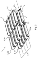
- the conveyor device 1 is shown in simplified form, with the conveyor device 1 being formed by a plurality of belt conveyor devices 3 .
- the conveyor 1 has a plurality of conveyor tracks 2, wherein the a plurality of conveyor tracks 2 are arranged parallel to one another, the plurality of conveyor tracks 2 being designed to be connected in order to convey the material together.
- four conveyor tracks 2 are shown, in principle any number of conveyor tracks, but preferably at least two conveyor tracks 2, can be formed.
- the conveyor tracks 2 run, for example, from the material receiving device 34 to the processing device 35 of the agricultural machine 30.
- the conveyor device 1 has a lateral delimiting section (not shown) in order to delimit the outer conveyor tracks 2.
- the delimiting sections are suitable for guiding the flow of material and/or for compressing it during transport.
- the delimiting sections are suitable for guiding the flow of material and/or for compressing it during transport.
- several conveyor tracks 2 are designed to converge, so that the flow of material is compressed, with the lateral delimiting sections being designed in a funnel shape with the conveyor tracks 2 converging.
- the multiple belt conveyors 3 are arranged in multiple rows within the conveyor lanes 2 .
- the belt conveyor devices 3 are designed as double belt conveyors, which are arranged one above the other in a first and a second level E1, E2, with a conveyor corridor being formed between the two levels E1, E2.
- the conveyor corridor K is designed to be continuous, so that the plurality of belt conveyor devices convey the material flow along the conveyor corridor K together.
- the conveyor device 1 can only have the first level E1 of belt conveyor devices 3 .
- the belt conveyor devices 3 are generally designed as continuous conveyors, with the belt conveyor devices 3 having an endless conveyor belt 4 .
- the conveyor belt 4 is, for example, a rubberized webbing.
- the conveyor belt 4 has a profile structure or transverse lamellae in order to drive the flow of material.
- the belt conveyor devices 3 have a support frame 5 and first and second support rollers 6a, 6b, the support rollers 6a, 6b being arranged at a first and a second end of the support frame 5, the conveyor belt 4 being deflected by the support rollers 6a, 6b are added to the support frame 5.
- the belt conveyor device 3 has a drive unit for driving the conveyor belt 4, the drive unit having one or both support rollers 6a, 6b in terms of drive technology connected is.
- a belt conveyor device 3 of the first level E1 can be formed together with a belt conveyor device 3 of the second level E2 (double belt conveyor). Consequently, the belt conveyor device 3 has a first and a second conveyor belt 4a, 4b.
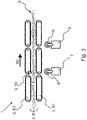
- the conveyor device 1 is shown in a schematic side view.
- the conveyor device 1 has, as already in figure 2 shown, two levels E1, E2 of belt conveyors 3, which together transport the material flow S along the conveyor track 2.
- the belt conveyor devices 3 are shown in simplified form, with three belt conveyor devices 3 being arranged one behind the other on each level E1, E2.
- the material flow S can be conveyed in a conveying direction R2, the conveying direction R2 being formed, for example, from the material receiving device 34 to the processing device 35.
- the conveyor device 1 has a cutting device 7 for separating material from the material flow S.
- the cutting device 7 is, as already the belt conveyors 3, in the figure 3 shown in a highly schematic manner.
- the cutting device 7 is arranged outside the conveyor track 2, with several cutting devices 7 being formed according to the exemplary embodiment.
- the cutting device 7 has at least one cutting blade 8 for cutting the stream of material S.
- the cutting blades 8 are designed, for example, as rotary cutting blades, the cutting blades being designed to be rotatable on the cutting device 7, the cutting device 7 having an electrical or mechanical drive, for example, the drive being designed to drive the cutting blades.
- FIG 3 is shown how the material flow S is conveyed uncut in the conveying direction R2.
- the conveyor device 1 has a sorting device 9 with at least one sensor 10 .
- the sorting device 9 is shown only schematically, with the sensor 10 being designed to detect a foreign body F in the material flow S.
- sensor 10 is embodied as an inductive sensor, with foreign body F, e.g. a metal splinter, being transported through material receiving device 34 into conveyor device 1, with sorting device 9 being embodied to detect foreign body F, so that conveying direction R2 is in a Ejection direction R3 can be changed.
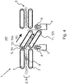
- the belt conveyor devices 3 are pivotable, so that the material flow S can be and/or can be deflected from the conveying direction R2 into the ejection position R3.
- the conveyor device 1 is shown with pivoted belt conveyors 3, a pair of belt conveyors 3 being pivoted.
- the two belt conveyor devices 3, one belt conveyor device 3 each on the first and on the second level E1, E2, are arranged with an ejection section 11 outside the conveyor track 2.
- the ejection section 11 is designed, for example, as a pivotable end and/or as a second deflection station section 12b of the belt conveyor device 3 .
- the belt conveyor device 3 has a first and a second deflection station section 12a, 12b, the deflection station sections 12a, 12b being designed for deflecting the conveyor belts 4.
- At least two belt conveyor devices 3 are according to the embodiment in figure 4 placed in an ejection position AP.
- the ejection section 11 is arranged below the conveyor track 2 .
- the ejection direction R3 is defined by the two-sided guidance of the two belt conveyor devices 3 in the ejection position AP.
- the ejection direction R3 is offset by at least 35°, in particular by at least 45°, to the conveying direction R2, so that the material flow S is deflected in the direction of the cutting device 7.
- the cutting device 7 can be arranged on the ejection section 11 so that it can also be pivoted into the ejection position AP, with the cutting device 7 being designed only for cutting out a strip of material T when it is conveyed in the ejection direction R3.
- the The cutting blade 8 is designed to be extendable by a lifting device, so that the cutting blade 8 can be moved into the material flow S in the ejection position AP to the side of the belt conveyor device 3 .
- the conveyor device 1 has the sorting device 9 with the at least one sensor 10 which is arranged on a pivoting section 13 of the belt conveyor device 3 .
- the pivoting section 13 is designed, for example, as the first deflection station section 12a, with the two ends of the belt conveyor device 3 being pivotable about a respective pivoting axis between a conveying position FP and the ejection position AP.
- the sorting device 9 is designed to eject the foreign body F from the conveyor device 1 by pivoting the respective belt conveyor devices 3 into the ejection position AP.
- the inductive sensor detects the foreign body F, with the sorting device 9 sending a control signal to the corresponding belt conveyor devices 3 for swiveling out in pairs into the ejection position AP, so that the material flow S with the foreign body F is deflected.
- the path covered by the foreign body F in the direction of the ejection section 11 is indicated as a dashed line, with the cutting device 7 at the end of the ejection section 11 cutting a material section T with the foreign body F from the material flow S in the ejection direction R3.
- the length of material T is shown in an ejected condition.
- the belt conveyors 3 are arranged in the conveying position FP, with the ejection section 11 being arranged inside the conveying path 2 in the conveying position FP.
- the sorting device 9 is designed, after ejection of the Material section T with the foreign body F to send a further control signal to the belt conveyor devices 3, wherein the belt conveyor devices 3 pivot back into the conveying position FP, so that the material flow S is introduced into the conveyor track 2 and/or can be introduced.
- the belt conveyor device 3 tears off the material section T, for example, transversely to the ejection direction R3.
- the cutting device 7 has a cross-cutting blade, the cross-cutting blade being arranged, for example, on the respectively following belt conveyor device 3 below or adjacent to the first deflection station section 12a. After being cut out by the cutting device 7, the material section T with the foreign body F falls, for example, into a collection container of the agricultural machine 30, so that it can be disposed of and cannot be picked up again on the agricultural area.
- the material flow S is shown in a highly schematic manner, with several material sections T being separated from the material flow S.
- the conveyor tracks 2 are indicated by a number of dashed lines, with the cut-out material sections T essentially having the width of a conveyor track 2 .
- the belt conveyor devices 3 are designed to pivot independently and individually from one another between the conveying position FP and the ejection position AP. As a result, only a “small” material section T, in relation to the entire width of the material flow S, is separated out when the foreign body F is sorted out.
Landscapes
- Life Sciences & Earth Sciences (AREA)
- Environmental Sciences (AREA)
- Engineering & Computer Science (AREA)
- Mechanical Engineering (AREA)
- Sorting Of Articles (AREA)
Abstract
Description
- Die Erfindung betrifft eine Fördervorrichtung für eine landwirtschaftliche Maschine zur Förderung eines Materialstroms eines Materials mit den Merkmalen des Oberbegriffs des Anspruch 1. Ferner betrifft die Erfindung eine landwirtschaftliche Maschine mit einer Fördervorrichtung mit den Merkmalen des Anspruch 14.
- Bekannt sind Förderanlagen, z.B. Bandförderer oder Rollenförderer, zum Fördern von Materialien, z.B. Schüttgut oder einzelnen Objekten. Beispielsweise als Bandförderer weist diese ein oder mehrere angetriebene Förderbänder auf, welcher die Materialien über kurze oder lange Strecken und/oder über Steigungen befördert. Die Förderanlagen können Verteilungs- und/oder Lenkungseinrichtungen aufweisen, um die Materialen über ein Fördernetz der Förderanlage an unterschiedliche Orte zu befördern. Zudem sind Sortieranlagen bekannt, welche die geförderten Materialien auf der Förderanlage erkennen, um diese zu verteilen oder auszusondern. Förderanlagen sind zudem in der Landwirtschaft bekannt, um beispielsweise ein Erntegut, z.B. Getreide, von einem Schneid- und/oder Mähwerk in eine Verarbeitungsanlage der landwirtschaftlichen Maschine zu befördern. Die Förderanlage ist beispielsweise als ein Kettenförderer ausgebildet, wobei eine Sicherheitsanlage ausgebildet ist, Fremdkörper im Erntegut zu erkennen und diese auszusondern.
- Dabei zeigt die Druckschrift
DE 10 2004 035 928 A1 eine landwirtschaftliche Arbeitsmaschine mit einer Schutzvorrichtung im Einzugsbereich eines Arbeitsorgans. Die Schutzvorrichtung weist einen Fremdkörperdetektor auf, mit dem Fremdkörper im Erntegutstrom detektiert werden, wobei der Fremdkörperdetektor aus mehreren quer zur Fahrtrichtung der landwirtschaftlichen Arbeitsmaschine nebeneinander angeordneten Sensierelementen besteht, wobei die Sensierelemente die Fremdkörper unabhängig voneinander ortsaufgelöst detektieren. - Der Erfindung liegt die Aufgabe zugrunde, eine Fördervorrichtung für eine landwirtschaftliche Maschine zu schaffen, welche eine erhöhte Detektionssicherheit aufweist und sich durch einen geringen Ausschuss an Material beim Auswerfen des Fremdkörpers auszeichnet.
- Diese Aufgabe wird durch eine Fördervorrichtung für eine landwirtschaftliche Maschine mit den Merkmalen des Anspruchs 1 sowie durch eine landwirtschaftliche Maschine mit der Fördervorrichtung mit den Merkmalen des Anspruch 14 gelöst. Bevorzugte oder vorteilhafte Ausführungsformen der Erfindung ergeben sich aus den Unteransprüchen, der nachfolgenden Beschreibung und/oder den beigefügten Figuren.
- Die Erfindung betrifft eine Fördervorrichtung für eine landwirtschaftliche Maschine zur Förderung eines Materialstroms eines Materials, insbesondere eines Materialstroms eines Erntegutes. Vorzugsweise fördert die Fördervorrichtung einen kontinuierlichen Materialstrom aus dem Material. Beispielsweise ist das Material als oberirdische Biomasse von Pflanzen und/oder Pflanzenhalme ausgebildet, wobei der Materialstrom durch das lose zusammenhängende Material als eine Art Materialgeflecht und/oder - matte ausgebildet ist. Unter Materialstrom ist grundsätzlich ein Fördergut in Bewegung zu verstehen, welcher von einer Aufnahmestelle zu einer oder mehreren Entnahmestellen der Fördervorrichtung befördert werden kann. Grundsätzlich kann ein beliebiges Erntegut und/oder Nebenprodukt bei der Ernte als Material mit der Fördervorrichtung befördert werden. Besonders bevorzugt ist das Material als Heu, Stroh und/oder Grassilage ausgebildet.
- Die landwirtschaftliche Maschine ist vorzugsweise geeignet, das Material auf einer landwirtschaftlichen Fläche aufzunehmen und/oder zu ernten und der Fördervorrichtung zum Fördern zu übergeben. Vorzugsweise weist die landwirtschaftliche Maschine eine Verarbeitungsvorrichtung auf, wobei die Fördervorrichtung zum Fördern des Materialstrom zu der Verarbeitungsvorrichtung ausgebildet ist. Die landwirtschaftliche Maschine oder die Verarbeitungsvorrichtung ist beispielsweise als eine Ballenpresse ausgebildet, wobei die Ballenpresse ausgebildet ist, das lose Material aufzunehmen und zu Materialballen oder Materialpacken zu pressen beziehungsweise zu wickeln. Die Fördervorrichtung ist vorzugsweise zwischen einer Materialaufnahmevorrichtung und der Verarbeitungsvorrichtung der landwirtschaftlichen Maschine fördertechnisch geschaltet und/oder ausgebildet. Alternativ weist die Fördervorrichtung Mittel zur Aufnahme des Materials auf, sodass die Fördervorrichtung vor die landwirtschaftliche Maschine beziehungsweise die Verarbeitungsvorrichtung fördertechnisch geschaltet und/oder ausgebildet ist.
- Die Fördervorrichtung weist mindestens eine Förderbahn zur Beförderung des Materialstroms auf. Die Förderbahn ist bevorzugt als eine gerade Bahn und/oder Strecke ausgebildet, wobei die Förderbahn im Wesentlichen die Strecke und/oder die Entfernung darstellt, welche das Material durch die Fördervorrichtung befördert wird und/oder beförderbar ist. Vorzugsweise ist die Förderbahn ansteigend ausgebildet, sodass der Materialstrom über einen Anstieg durch die Fördervorrichtung gefördert wird und/oder förderbar ist. Beispielsweise ist die Förderbahn an der landwirtschaftlichen Maschine zum Überwinden eines Höhenunterschiedes zwischen der landwirtschaftlichen Fläche und/oder der Materialaufnahmevorrichtung und der Verarbeitungsvorrichtung schräg angeordnet.
- Ferner definiert die Förderbahn eine Förderrichtung für den Materialstrom. Die Förderbahn weist vorzugsweise die Aufnahmestelle und die Entnahmestelle auf, wobei der Materialstrom in Förderrichtung von der Aufnahmestelle zu der Entnahmestelle beförderbar ist. Die Förderbahn ist vorzugsweise zum Führen des Materialstroms ausgebildet, wobei die Förderbahn vorzugsweise seitliche Begrenzungsabschnitte aufweist. Die Begrenzungsabschnitte sind geeignet, den Materialstrom zu führen und/oder diesen zu komprimieren. Beispielsweise sind die seitlichen Begrenzungsabschnitte trichterförmig an der Förderbahn angeordnet, sodass der Materialstrom beim Vorbeibewegen verdichtet wird.
- Die Fördervorrichtung weist mindestens eine Bandfördereinrichtung zum Fördern des Materialstroms auf, wobei die Bandfördereinrichtung innerhalb der Förderbahn angeordnet ist. Die Bandfördereinrichtung ist vorzugsweise als ein Stetigförderer ausgebildet, wobei die Bandfördereinrichtung vorzugsweise mindestens ein Förderband aufweist. Das Förderband ist vorzugsweise als ein Gurtband, z.B. ein gummiertes Gurtband, ausgebildet, wobei das Förderband als ein endloses Band ausgebildet ist. Die Bandfördereinrichtung weist mindestens eine Antriebseinheit zum Antreiben des Förderbandes auf. Beispielsweise treibt die Antriebseinheit ein oder mehrere Rollen der Bandfördereinrichtung an, wobei die Rollen rotierbar innerhalb des Förderbandes zum endlosen Umlaufen des Förderbandes angeordnet sind. Optional ist das Förderband als eine Schräg- oder Steilförderband ausgebildet, wobei das Förderband mehrere Querlamellen zur Mitnahme des Materialstroms aufweist.
- Die Bandfördereinrichtung ist innerhalb der Förderbahn angeordnet, wobei die Bandfördereinrichtung vorzugsweise zumindest in einem Bahnabschnitt der Förderbahn zum fördertechnischen Antreiben des Materialstroms angeordnet ist. Beispielsweise ist die Bandfördereinrichtung an einem bodenseitigen Bahnabschnitt der Förderbahn angeordnet, wobei der Materialstrom oberhalb der Bandfördereinrichtung auf dem Förderband beförderbar ist. Bevorzugt bilden ein oder mehrere Bandfördereinrichtung die Förderbahn. Alternativ ist die Bandfördereinrichtung an einem seitlichen Bahnabschnitt der Förderbahn angeordnet, wobei die Bandfördereinrichtung beispielsweise die Querlamellen und/oder Transportstege zur Mitnahme des Materialstroms entlang der Förderbahn aufweist.
- Ferner weist die Bandfördereinrichtung einen Auswurfabschnitt zum Ausschwenken aus der Förderbahn auf. Der Auswurfabschnitt ist vorzugsweise als ein Endabschnitt der Bandfördereinrichtung ausgebildet, wobei die Bandfördereinrichtung mit dem Auswurfabschnitt zum Auswerfen von Material ausgebildet ist. Insbesondere weist die Bandfördereinrichtung einen Schwenkabschnitt auf, wobei der Schwenkabschnitt mit dem Auswurfabschnitt wirktechnisch verbunden ist, wobei der Schwenkabschnitt beim Ausschwenken des Auswurfabschnitt innerhalb der Förderbahn verbleiben angeordnet ist. Der Schwenkabschnitt weist vorzugsweise eine Schwenkachse auf, wobei die Bandfördereinrichtung um die Schwenkachse schwenkbar ausgebildet ist, um den Auswurfabschnitt aus der Förderbahn zu schwenken. Vorzugsweise ist der Auswurfabschnitt in Förderrichtung nach dem Schwenkabschnitt ausgebildet. In Förderrichtung hinter und/oder vor dem Auswurfabschnitt können benachbarte Bandfördereinrichtungen zu einer gemeinsamen Bandfördereinrichtung zusammengefasst sein. Die Förderbahn ist dann als eine gedachte Förderbahn zu verstehen.
- Ferner ist vorgesehen, dass die Bandfördereinrichtung aus der Förderbahn schwenkbar ausgebildet ist, um den Materialstrom von der Förderrichtung in eine Auswerfrichtung umzulenken. Die Auswerfrichtung ist vorzugsweise um einen Winkel von mindestens 30°, bevorzugt von mindestens 45°, im Speziellen von mindestens 60°, zu der Förderrichtung versetzt ausgebildet. Die Förderrichtung führt den Materialstrom vorzugsweise weiter zur landwirtschaftlichen Maschine und/oder der Verarbeitungsvorrichtung der landwirtschaftlichen Maschine, wobei die Auswerfrichtung derart ausgebildet ist, dass der Materialstrom aus der Fördervorrichtung und/oder der landwirtschaftlichen Maschine geführt ist. Die Bandfördereinrichtung ist in Auswerfrichtung schwenkbar und/oder definiert diese durch die Schwenkrichtung. Beispielsweise fördert die Bandfördereinrichtung stetig das Material entlang der Förderbahn in Richtung der Förderrichtung, wobei beim Schwenken der Bandfördereinrichtung aus der Förderbahn der Materialstrom zum Auswerfen aus der Fördervorrichtung in Auswerfrichtung umgelenkt ist.
- Im Rahmen der Erfindung wird vorgeschlagen, dass die Fördervorrichtung mindestens eine Schneideeinrichtung aufweist, um den Materialstrom beim Fördern in die Auswerfrichtung von dem in Förderrichtung geförderten Materialstrom zu trennen. Die Schneideeinrichtung ist beispielsweise geeignet, den Materialstrom in einem Trennverfahren zu trennen. Beispielsweise trennt die Schneidevorrichtung den Materialstrom in einem spanenden Fertigungsverfahren, z.B. durch Sägen, und/oder in einem Trennverfahren, wie z.B. durch Scherschneiden. Die Schneideeinrichtung weist vorzugsweise mehrere Schneidemesser zum Schneiden auf, um den Materialstrom entlang der Auswerfrichtung, insbesondere längs der Auswerfrichtung, zu schneiden. Der Materialstrom ist durch das Schwenken der Bandfördereinrichtung in Auswerfrichtung führbar, wobei der Materialstrom der Scheideeinrichtung zum Austrennen von Material zugeführt wird und/oder zuführbar ist. Vorzugsweise ist die Scheideeinrichtung stationär an der Fördervorrichtung angeordnet, sodass der Materialstrom beim Fördern in Auswerfrichtung durch die stationären Scheidemesser zum Schneiden in Längsrichtung in Bezug auf die Auswerfrichtung geschnitten wird und/oder schneidbar ist. Die Schneidemesser sind vorzugsweise als Rollenschneidemesser oder als Säge- und/oder Schneideblätter ausgebildet, wobei die Schneidemesser rotierbar an der Schneidevorrichtung angeordnet sind. Alternativ sind die Schneidemesser als Schneidbalken und/oder Trennmesser und/oder Schermesser zum Spalten oder Scherscheiden oder Stanzen ausgebildet. Die Schneidemesser sind vorzugsweise benachbart zur Förderbahn ausgebildet. Besonders bevorzugt weist die Schneideeinrichtung mindestens zwei Schneidemesser auf, wobei mindestens jeweils ein Schneidemesser randseitig der Förderbahn angeordnet ist, sodass die mindestens zwei Schneidemesser parallel zueinander an zwei gegenüberliegenden Seiten der Förderbahn angeordnet sind. Besonders bevorzugt trennt die Schneideeinrichtung den Materialstrom lediglich beim Fördern in Auswerfrichtung, wobei beim Fördern in Förderrichtung der Materialstrom zusammenhängend ausgebildet ist. Die Schneideeinrichtung ist vorzugsweise an der Fördervorrichtung zum Trennen des Materialstrom in Förderrichtung von einem weiteren Materialstrom in Auswerfrichtung angeordnet. Beispielsweise ist der Materialstrom aus einem kontinuierlich geförderten und zusammenhängenden Material gebildet, wobei beim Umleiten von der Förderrichtung in die Auswerfrichtung der Materialstrom von der Scheideeinrichtung geschnitten wird und/oder schneidbar ist.
- Vorteilhaft ist, dass die Fördervorrichtung mit der Bandfördereinrichtung ausgebildet ist, den Materialstrom von der Förderrichtung in die Auswerfrichtung umzuleiten, wobei die Fördervorrichtung die Schneideeinrichtung aufweist, um den Materialstrom aus zusammenhängendem Material, z.B. Stroh, beim Umlenken zu trennen, sodass eine Fördervorrichtung geschaffen, welche besonders unanfällig für Störungen, z.B. Materialstau, beim Fördern und/oder Umlenken des Materialstroms ist. Besonders vorteilhaft ist, dass durch das Umlenken in Auswerfrichtung eine Fördervorrichtung geschaffen ist, welche Material mit Fremdkörpern, z.B. Steine oder metallische Objekte, auswerfen kann, sodass die landwirtschaftliche Maschine vor Beschädigungen durch den Fremdkörper geschützt ist. Beispielsweise ist die landwirtschaftliche Maschine als Ballenpresse zur Herstellung von Stroh-, Heu- und/oder Grassilagenballen ausgebildet, wobei beispielsweise die Strohballen als Futtermittel oder Futterzugabe für Kühe und/oder Rinder dienen. Durch die Fördervorrichtung können Fremdkörper vor der Verarbeitung des Materials, z.B. zu Strohballen, ausgeworfen werden, sodass verhindert wird, dass Tiere beim Füttern mit dem Material (Stroh) durch die Fremdkörper verletzt werden oder sogar daran verenden. Die Fördervorrichtung wirft durch ein exaktes Austrennen der Schneideeinrichtung beim Auswerfen eines Fremdkörpers besonders wenig nutzbares Materials mit aus. Dadurch ist eine Fördervorrichtung mit Schneideeinrichtung geschaffen, welche sich durch einen geringen Ausschuss an Material beim Auswerfen des Fremdkörpers auszeichnet.
- In einer bevorzugten Ausgestaltung der Erfindung ist vorgesehen, dass die Schneideeinrichtung an der Bandfördereinrichtung oder benachbart zur Bandfördereinrichtung seitens des Auswurfabschnitts zum Austrennen des Materialstroms angeordnet ist. Beispielsweise ist die Schneideeinrichtung an der Bandfördereinrichtung angeordnet, wobei die Schneideeinrichtung vorzugsweise mit dem Auswurfabschnitt verbunden ist. Die Schneideeinrichtung ist ausgebildet, den Materialstrom beim Verschwenken des Auswurfabschnitts aus der Förderbahn zu trennen. Vorzugsweise ist dazu vorgesehen, dass die Schneideeinrichtung mit dem Auswerfabschnitt der Bandfördereinrichtung mit verschwenkbar ausgebildet ist. Die Schneideeinrichtung weist vorzugsweise einen Hebeeinrichtung zum Ausfahren von Schneidemessern auf. Die Hebeeinrichtung fährt die Schneidemesser beispielsweise beim Schwenken der Bandfördereinrichtung in Auswerfrichtung aus, sodass die Schneidemesser den Materialstrom beim Fördern in Auswerfrichtung durchtrennen. Die Hebeeinrichtung ist vorzugsweise ausgebildet, die Schneidemesser beim Zurückschwenken der Bandfördereinrichtung in die Förderbahn einzuklappen, sodass der Materialstrom ungetrennt in Förderrichtung beförderbar ist. Vorzugsweise sind die Schneidemesser der Schneideeinrichtung durch den Antrieb der Bandfördereinrichtung mit antreibbar ausgebildet.
- Alternativ ist die Schneideeinrichtung benachbart zu dem Auswurfabschnitt angeordnet. Vorzugsweise ist die Schneideeinrichtung in einem Auswurfbereich des Materialstroms in Auswerfrichtung angeordnet. Die Scheidevorrichtung ist insbesondere stationär mit der Fördervorrichtung verbunden, sodass der Materialstrom beim Schwenken in Auswerfrichtung in einen Schneidebereich der Schneideeinrichtung geführt wird und/oder führbar ist. Beispielseise weist die Schneideeinrichtung rotierende Rollenschneidemesser auf, welche beispielsweise unterhalb der Förderbahn angeordnet sind, wobei die Bandfördereinrichtung mit dem Auswurfabschnitt in den Schneidebereich der Scheideeinrichtung schwenkbar ist. Vorzugsweise sind die Schneidemesser mit der Fördervorrichtung und/oder der landwirtschaftlichen Maschine antriebstechnisch verbunden. Alternativ weist die Schneideeinrichtung eine Motoreinheit zum Rotieren oder zum Stanzbewegen der Scheidemesser auf.
- In einer bevorzugten Ausgestaltung der Erfindung ist vorgesehen, dass die Bandfördereinrichtung zwischen einer Förderposition und einer Auswerfposition schwenkbar ist, wobei in der Förderposition die Bandfördereinrichtung den Materialstrom in Förderrichtung befördert, wobei in der Auswerfposition die Bandfördereinrichtung den Materialstrom in Auswerfrichtung befördert. Insbesondere ist der Auswurfabschnitt der Bandfördereinrichtung zwischen der Förderposition und der Auswurfposition schwenkbar, vorzugsweise um die Schwenkachse des Schwenkabschnittes der Bandfördereinrichtung. Vorzugsweise weist die Bandfördereinrichtung eine Schwenkeinheit zum Ausführen der Schwenkbewegung auf. Die Schwenkeinheit ist vorzugsweise als ein elektromechanischer oder hydraulischer Schwenkmechanismus ausgebildet. Beispielsweise weist der Schwenkmechanismus einen elektrischen Motor und ein Schwenkgestänge auf, wobei der elektrische Motor mit dem Schwenkgestänge zum Stellen der Bandfördereinrichtung in die Förder- und Auswerfposition antriebstechnisch verbunden ist. Alternativ ist der Schwenkmechanismus über einen mechanischen Antrieb der landwirtschaftlichen Maschine antreibbar. Beispielsweise wird das Schwenkgestänge der Schwenkeinheit über eine Koppelstange der landwirtschaftlichen Maschine angetrieben und/oder betätigt, sodass die Bandfördereinrichtung zwischen der Förder- und Auswerfposition schwenkbar ist.
- Ferner ist vorgesehen, dass die Schneideeinrichtung in der Auswerfposition den Materialstrom trennt, um zumindest einen Materialabschnitt des Materialstroms zum Auswurf aus der Fördervorrichtung aus zu trennen. Die Schneideeinrichtung ist in der Auswerfposition zum Austrennen von zumindest einem Materialabschnitt des Materialstroms ausgebildet. Der Materialabschnitt weist beispielsweise einen Fremdkörper auf, wobei die Schneideeinrichtung den Materialabschnitt zusammen mit dem Fremdkörper aus dem Materialstrom austrennt, sodass die in Auswerfposition geschwenkte Bandfördereinrichtung diese aus der Fördervorrichtung auswirft. Vorteilhaft ist, dass ein Materialabschnitt aus dem Materialstrom austrennbar ist, sodass beispielsweise ein Fremdkörper, welcher mit dem Material verbunden und/oder eingeschlossen ist, aus der Förderbahn und/oder der Fördervorrichtung zuverlässig ausgeworfen werden kann. Durch die Schneideeinrichtung ist sichergestellt, dass der auszuwerfende Materialabschnitt von dem Materialstrom getrennt wird, wobei die Abschnittsgröße des Materialabschnitts an den zu entfernenden Fremdkörper anpassbar ist. Beispielsweise weist der Materialabschnitt eine Flächenausdehnung von mindestens 50 cm2, bevorzugt von mindestens 100 cm2, im Speziellen von mindestens 300 cm2, auf.
- In einer bevorzugten Weiterentwicklung der Erfindung ist vorgesehen, dass die Schneideeinrichtung den Materialstrom in der Auswerfposition der Bandfördereinrichtung in Auswerfrichtung trennt, wobei beim Zurückschwenken der Bandfördereinrichtung in die Förderposition die Schneideeinrichtung den Materialstrom quer zur Auswerfrichtung trennt. Die Schneideeinrichtung ist zum Trennen des Materialstroms in Auswerfrichtung in der Auswerfposition der Bandfördereinrichtung ausgebildet, wobei die Schneideeinrichtung zum Quertrennen des Materialstroms beim Zurückschwenken der Bandfördereinrichtung in die Förderposition ausgebildet ist. Die Schneideeinrichtung weist mindestens ein Querschneidemesser und/oder einen Schneidebalken zum Schneiden des Materialstroms auf. Das Querscheidemesser ist vorzugsweise an der Förderbahn benachbart zu dem Ausschwenkabschnitt der Bandfördereinrichtung angeordnet, sodass beispielsweise beim Hochziehen des Materialstroms in die Förderbahn der Materialabschnitt durch das Querschneidemesser quer geschnitten wird. Alternativ ist das Querschneidemesser an der Bandfördereinrichtung angeordnet, wobei das Querschneidemesser endseitig an dem Auswerfabschnitt angeordnet ist. Vorzugsweise ist das Querschneidemesser der Schneidevorrichtung mit der Hebeeinrichtung zum Ausfahren wirkverbunden, wobei das Querschneidemesser beispielsweise beim Verlagern der Bandfördereinrichtung von der Auswerfposition in die Förderposition zum Abtrennen des Materialabschnitts von dem nachlaufenden Materialstrom durch die Hebeeinrichtung ausgefahren wird und/oder ausfahrbar ist.
- In einer weiteren bevorzugten Ausgestaltung der Erfindung ist vorgesehen, dass die Fördervorrichtung mindestens zwei, insbesondere genau zwei oder mehr als zwei, benachbarte Förderbahnen zur gemeinsamen Beförderung des Materialstroms aufweist. Die Förderbahnen bilden vorzugsweise eine gemeinsame Förderfläche zum Befördern des Materialstroms, wobei die Förderbahnen in ihrer Ausdehnung und/oder Ausgestaltung vorzugsweise gleich ausgebildet sind. Die Förderbahnen sind vorzugsweise gleichlang ausgebildet, wobei die Förderbahnen vorzugsweise parallel zueinander angeordnet sind. Besonders bevorzugt weist die Fördervorrichtung mindestens drei oder genau drei Förderbahnen auf.
- Ferner ist vorgesehen, dass die Fördervorrichtung mindestens zwei, insbesondere genau zwei oder mehr als zwei, Bandfördereinrichtungen aufweist, wobei jeweils mindestens eine der Bandfördereinrichtungen in einer der Förderbahnen zum gemeinsamen Befördern des Materialstroms angeordnet ist. Vorzugsweise sind mehrere Bandfördereinrichtungen hintereinander in Reihe in einer Förderbahn angeordnet, wobei mindestens eine weitere Förderbahn mit mehreren Bahnfördereinrichtungen parallel zu dieser zum gemeinsamen Befördern des Materialstroms angeordnet ist. Die mehreren Bandfördereinrichtungen befördern den Materialstrom vorzugsweise mit einer gemeinsamen Fördergeschwindigkeit in Förderrichtung, wobei die mehreren Bandfördereinrichtungen einzeln schwenkbar ausgebildet sind. Die einzelnen Bandfördereinrichtungen sind unabhängig voneinander schwenkbar ausgebildet, sodass die Bandfördereinrichtungen unabhängig der Förderbahn und ihrer Anordnung auf dieser schwenkbar sind. Insbesondere weist jede der Bandfördereinrichtungen eine Förderposition und Auswerfposition auf.
- In einer bevorzugten Weiterentwicklung der Erfindung ist vorgesehen, dass die mindestens zwei oder genau zwei Bandfördereinrichtungen einzeln schwenkbar ausgebildet sind. Bevorzugt sind die mindestens zwei Bandfördereinrichtungen jeweils zwischen einer Förderposition innerhalb der jeweiligen Förderbahn und einer Auswerfposition außerhalb der jeweiligen Förderbahn schwenkbar ausgebildet. Beispielsweise schwenkt lediglich die Bandfördereinrichtung von der Förderposition in die Auswerfposition aus, auf deren Förderbahn sich der Fremdkörper, z.B. ein Metallsplitter, befindet.
- Ferner ist vorgesehen, dass die Scheideeinrichtung zwischen den Bandfördereinrichtungen zum Austrennen von einzelnen Materialabschnitten des Materialstroms aus der jeweiligen Förderbahn ausgebildet ist. Vorzugsweise weist die Schneideeinrichtung mehrere Scheidemesser auf, wobei die mehreren Scheidemesser, z.B. jeweils zwei Scheidemesser, an jeweils einer Bandfördereinrichtung zum selektiven Austrennen von Materialabschnitten angeordnet sind. Beispielsweise ist der Materialabschnitt als ein Materialstreifen mit einer Streifenbreite ausgebildet, welche der Bahnbreite der jeweiligen Förderbahn entspricht. Folglich wird eine Auswurfgenauigkeit und/oder eine Selektionsgenauigkeit zum Austrennen des Fremdkörpers durch die Anzahl der benachbarten Förderbahnen und der Anzahl ihrer Bandfördereinrichtungen bestimmt. Die Materialabschnitte weisen vorzugsweise eine Breite von mindesten 3 cm, bevorzugt von mindesten 5 cm, im Speziellen von mindestens 10 cm, auf.
- In einer bevorzugten Ausgestaltung der Erfindung ist vorgesehen, dass die Bandfördereinrichtung ein erstes und ein zweites Förderband zum Führen des Materialstroms aufweist. Die Förderbänder sind vorzugsweise als Gurtbänder ausgebildet, wobei die Förderbänder vorzugsweise aus einem Gummi- oder Kunststoffmaterial mit einer textilen Gewebeeinlage hergestellt sind. Alternativ sind die Förderbänder aus Metall, z.B. als Kettenförderer und/oder Kettenförderband, gefertigt oder weisen ein metallische Gewebeeinlage oder Stützstruktur auf. Optional weisen die Förderbänder die Querlamellen und/oder Transportstege zum Antreiben des Materialstroms auf. Das erste und das zweite Förderband sind beabstandet zueinander angeordnet, sodass zwischen dem ersten und dem zweiten Förderband ein Förderkorridor zur zweiseitigen Führung des Materialstroms ausgebildet ist. Vorzugsweise sind das erste und das zweite Förderband übereinander angeordnet, sodass zwischen diesen der Förderkorridor gebildet ist. Vorzugsweise bilden die mehreren Bandfördereinrichtungen in den mehreren Förderbahnen mit den ersten und den zweiten Förderbändern gemeinsam den Förderkorridor.
- Alternativ ist das erste und das zweite Förderband seitlich der Förderbahn ausgebildet, sodass die Bandfördereinrichtung zum seitlichen Auswerfen von Material aus der Förderbahn schwenkbar ausgebildet ist. Vorzugsweise weist das erste und das zweite Förderband mehrere Transportstege zur Mitnahme des Materials beidseitig entlang der Förderbahn auf. Vorzugsweise ist die Bandfördereinrichtung als ein Doppelgurtförderer ausgebildet, wobei die Bandfördereinrichtung als erstes Förderband einen Hauptfördergurt und als zweites Förderband einen Deckfördergurt aufweist.
- In einer bevorzugten konstruktiven Weiterentwicklung der Erfindung ist vorgesehen, dass die Bandfördereinrichtung einen ersten und einen zweiten Umlenkstationsabschnitt zum Umlenken des ersten und des zweiten Förderbandes aufweist. Der erste und der zweite Umlenkstationsabschnitt weisen vorzugsweise mehrere Tragrollen zur Förderbandführung auf, wobei die Förderbänder von dem ersten Umlenkstationsabschnitt zu dem zweiten Umlenkstationsabschnitt endlos umlaufen. Vorzugsweise weist die Bandfördereinrichtung einen Tragrahmen auf, wobei der erste und der zweite Umlenkstationsabschnitt jeweils an zwei gegenüberliegenden Enden des Tragrahmens angeordnet sind. Insbesondere sind der erste und der zweite Umlenkstationsabschnitt miteinander verbunden, vorzugsweise stoffschlüssig verbunden. Ferner ist vorgesehen, dass die Bandfördereinrichtung mit dem zweiten Umlenkstationsabschnitt aus der Förderbahn schwenkbar ausgebildet ist. Der zweite Umlenkstationsabschnitt ist insbesondere mit Umlenkbereichen des ersten und des zweiten Förderbands aus der Förderbahn schwenkbar ausgebildet. Besonders bevorzugt schwenken beide Förderbänder gemeinsam in Auswerfrichtung aus der Förderbahn aus. Besonders bevorzugt ist der zweite Umlenkstationsabschnitt als der Auswerfabschnitt der Bandfördereinrichtung ausgebildet. Vorzugsweise ist der zweite Umlenkstationsabschnitt von der Förderposition in die Auswerfposition bewegbar ausgebildet.
- In einer bevorzugten Ausgestaltung der Erfindung ist vorgesehen, dass die Fördervorrichtung eine Sortiereinrichtung zur Steuerung des Auswurfs von Material und/oder Materialabschnitten des Materialstroms in Auswerfrichtung aus der Fördervorrichtung durch die Bandfördereinrichtung aufweist. Die Sortiereinrichtung weist vorzugsweise ein Rechenmodul zur Berechnung von Steuersignalen auf, wobei die Sortiereinrichtung mit der Bandfördereinrichtung zur Steuerung des Schwenkens und/oder einer Schwenkposition, insbesondere der Schwenkposition in Förderposition oder in Auswurfposition, datentechnisch verbunden ist. Vorzugsweise weist die Sortiereinrichtung ein Detektionsmodul zur Identifikation eines Fremdkörpers auf, wobei das Detektionsmodul mit dem Rechenmodul verbunden ist oder in diesem integriert ausgebildet ist. Das Detektionsmodul ist zum Erkennen eines Fremdkörpers in dem Materialstrom ausgebildet, wobei das Detektionsmodul beim Erkennen eines Fremdkörpers ein Identifikationssignal an das Rechenmodul sendet, wobei das Rechenmodul ausgebildet ist, auf Basis des Identifikationssignales eine oder mehrere Steuersignale an ein oder mehrere Bandfördereinrichtungen zu senden. Das Rechenmodul ist vorzugsweise ausgebildet, die Steuersignal in Abhängigkeit einer Fördergeschwindigkeit des Materialstroms zu erzeugen, sodass das Schwenken der Bandfördereinrichtung, bevor der Fremdkörper über den Auswerfabschnitt befördert ist, aufgeführt wird und/oder ausführbar ist. Vorzugsweise umfassen die Steuersignale eine oder mehrere Befehle für die Bandfördereinrichtung, insbesondere für die Schwenkeinheit und/oder die Antriebseinheit der Bandfördereinrichtung. Beispielsweis ist die Sortiereinrichtung ausgebildet, die Fördergeschwindigkeit der Bandfördereinrichtung zu steuern. Besonders bevorzugt weist die Fördervorrichtung mehrere Förderbahnen und mehrere Bandfördereinrichtungen auf, wobei die Sortiereinrichtung ausgebildet ist, die Bandfördereinrichtungen einzelnen anzusteuern, um die Bandfördereinrichtungen aus der jeweiligen Förderbahn zum Auswerfen des Materialabschnitts zu schwenken.
- In einer bevorzugten Weiterentwicklung der Erfindung ist vorgesehen, dass die Sortiereinrichtung mindestens einen Sensor zum Detektieren von Fremdkörper in dem Materialstrom aufweist, wobei der Sensor innerhalb der Förderbahn vor der Bandfördereinrichtung in Bezug auf die Förderrichtung und/oder an dem ersten Umlenkstationsabschnitt zum Abtasten des Materialstroms angeordnet ist. Die Sensoren sind vorzugsweise als ein optischer Sensor und/oder als ein induktiver Sensor zur Erkennung von metallischen Objekten ausgebildet. Beispielsweise ist der optische Sensor mit einem Aufnahmemodul der Sortiereinrichtung zur Erfassung von mehreren Bildern und/oder Bilddaten verbunden, wobei das Aufnahmemodul die mehreren Bilder und/oder Bilddaten an das Detektionsmodul zur Erkennung des Fremdkörpers in den mehreren Bildern und/oder den Bilddaten sendet.
- Alternativ oder optional ergänzend ist der Sensor als ein induktiver Sensor zur Erkennung von metallischen Objekten, z.B. Kronkorken, Schrauben oder dergleichen, ausgebildet, wobei der induktive Sensor vorzugsweise mit einem Erfassungsmodul der Sortiereinrichtung verbunden ist, wobei das Erfassungsmodul ausgebildet ist, Erfassungsbereichsdaten des induktiven Sensors dem Detektionsmodul bereitzustellen.
- Vorzugsweise weist die Fördervorrichtung die mehreren Förderbahnen mit den mehreren Bandfördereinrichtungen auf, wobei besonders bevorzugt mehrere Sensoren zum Erfassen mehrerer Überwachungsabschnitte der Förderbahnen angeordnet sind. Die Überwachungsabschnitte sind vor der jeweiligen Bandfördereinrichtung an den Förderbahnen angeordnet, wobei beim Befördern des Materialstroms dieser durch die Überwachungsabschnitte gefördert wird und/oder förderbar ist, um den Materialstrom abschnittsweise durch die Sensoren in den Überwachungsabschnitten zu erfassen.
- Alternativ oder optional ergänzend ist der Sensor an dem ersten Umlenkstationsabschnitt der Bandfördereinrichtung angeordnet, wobei der Sensor den durch die jeweilige Bandfördereinrichtung geförderten Teilbereich des Materialstrom unmittelbar erfasst, um Fremdkörper in diesem zu detektieren. Beispielsweise ist zwei oder mehr Sensoren seitlich des ersten Umlenkstationsabschnitt angeordnet, wobei die zwei oder mehr Sensoren zum Abtasten des Materialstroms auf dem Förderband gegenüberliegend angeordnet sind.
- In einer bevorzugten Weiterentwicklung der Erfindung ist vorgesehen, dass die Sortiereinrichtung zum Ansteuern eines Ausschwenkens der Bandfördereinrichtung nach Detektion des Fremdkörpers im Materialstrom ausgebildet ist, wobei, insbesondere nach dem Ansteuern, zumindest der Auswurfabschnitt, insbesondere der zweite Umlenkstationsabschnitt, im Speziellen der zweite Umlenkstationsabschnitt mit dem ersten und dem zweiten Förderband der Bandfördereinrichtung, außerhalb der Förderbahn zum Fördern in Auswerfrichtung angeordnet ist, um den Materialabschnitt mit dem Fremdkörper aus der Fördervorrichtung auszuwerfen. Nach dem Detektieren durch die Sortiereinrichtung ist die Bandfördereinrichtung vorzugsweise in der Auswerfposition angeordnet. Beispielsweise durchläuft ein Fremdkörper einen der Überwachungsabschnitte und/oder wird von einem auf die Förderbahn ausgerichteten Sensor erfasst, wobei die Sortiereinrichtung ausgebildet ist, ein Steuersignal an die entsprechende Bandfördereinrichtung zu senden, um diese in Auswurfrichtung und/oder in die Auswurfposition zu schwenken, sodass die Schneideeinrichtung den demensprechenden Materialabschnitt mit dem Fremdkörper aus dem Materialstrom austrennt, wobei der Materialabschnitt mit dem Fremdkörper aus der Förderbahn und/oder Fördervorrichtung ausgeworfen wird und/oder auswerfbar ist.
- Bei einer möglichen Weiterbildung der Erfindung ist vorgesehen, dass die Sortiereinrichtung und/oder eine weitere Steuereinrichtung ausgebildet ist, mehrere Auswurfabschnitte zeitgleich und/oder gemeinsam auszuklappen, um größere Störkörper aus dem Materialstrom und/oder einen breiteren Materialstrom in die Auswerfeinrichtung auszusondern. Diese Weiterbildung hat den Vorteil, dass auch Störkörper ausgesondert werden können, die breiter als eine einzige Förderbahn sind.
- Optional ergänzend kann bei dem gemeinsamen Ausklappen der Auswurfabschnitte vorgesehen ein, dass die Schneideinrichtungen in eine Parkposition verfahren werden, so dass diese beim Aussondern des Materialstroms keine Störkontur bilden. Mit dieser Ergänzung ist es möglich, dass der ausgesonderte Materialstrom ungeteilt ausgesondert werden kann. Damit ist es ebenfalls möglich, die breiteren Störkörper, wie z.B. ein Zaunabschnitt oder ein Tierkadaver, unzerschnitten auszustoßen.
- In einer weiteren Weiterentwicklung der Erfindung ist vorgesehen, dass die Sortiereinrichtung zum Ansteuern eines Einschwenkens der Bandfördereinrichtung nach Auswerfen des Materialabschnitts mit dem Fremdkörper ausgebildet ist, wobei, insbesondere nach dem Ansteuern, die Bandfördereinrichtung mit dem Auswerfabschnitt, insbesondere der zweite Umlenkstationsabschnitt, im Speziellen der zweite Umlenkstationsabschnitt mit dem ersten und dem zweiten Förderband der Bandfördereinrichtung, innerhalb der Förderbahn angeordnet ist, um den Materialstrom zurück in Förderrichtung zu fördern. Die Bandfördereinrichtung ist nach dem Auswerfen des Materialabschnitts mit dem Fremdkörper, und insbesondere nach dem Ansteuern der Sortiereinrichtung, in der Förderposition zum Befördern des Materialstroms in Förderrichtung angeordnet. Beispielsweise ist der Materialabschnitt mit dem Fremdkörper durch die Schneideeinrichtung ausgetrennt und durch die Bandfördereinrichtung in Auswerfrichtung aus der Förderbahn und/oder Fördervorrichtung ausgeworfen, z.B. zurück auf die landwirtschaftliche Fläche oder in einen Auffangbehälter der landwirtschaftlichen Maschine, wobei die Sortiereinrichtung der geschwenkten Bandfördereinrichtung ein Steuersignal zum Einschwenken in die Förderbahn und/oder in die Förderposition sendet, sodass der Materialstrom wieder vollständig in die Förderbahn in Richtung der Förderrichtung geleitet beziehungsweise befördert wird und/oder beförderbar ist.
- In einer bevorzugten Weiterentwicklung ist vorgesehen, dass die Bandfördereinrichtung, wie zuvor beschreiben, nach dem Auswerfen des Fremdkörpers wieder einschwenkbar ausgebildet ist, wobei die Sortiereinrichtung zum Ansteuern des Einschwenkens der Bandfördereinrichtung nach Detektion des Fremdkörpers beim Auswurf aus der Fördervorrichtung und/oder der Förderbahn ausgebildet ist, wobei die Sortiereinrichtung mindestens einen weiteren Sensor aufweist, wobei der weitere Sensor an dem zweiten Umlenkstationsabschnitt und/oder dem Auswurfabschnitt zur Detektion des Auswurfes des Fremdkörpers angeordnet ist. Vorzugsweise ist der weitere Sensor als ein optischer oder ein induktiver Sensor ausgebildet, um beispielsweise einen metallischen Fremdkörper zu erfassen. Vorteilhaft ist, dass der weitere Sensor sicherstellt, dass der Fremdkörper die Fördervorrichtung tatsächlich verlassen hat, sodass ein zu schnelles zurückschwenken der Bandfördereinrichtung verhindert wird. Ist der Fremdkörper beispielsweise nicht Ausgeworfen, beziehungsweise erfasst der weitere Sensor den Fremdkörper nicht beim Auswerfen, kann eine nachgeschaltete Bandfördereinrichtung in Auswerfrichtung geschwenkt werden, um sicherzustellen das der Fremdkörper nicht zur landwirtschaftlichen Maschine befördert wird. Alternativ oder optional ergänzend kann die Fördergeschwindigkeit verringert oder die Bandfördereinrichtungen angehalten werden. Zudem ist vorteilhaft, dass der ausgeworfene Materialabschnitt möglichst klein gehalten wird, da unmittelbar nach dem detektieren des Auswurfes die Bandfördereinrichtung zurückgeschwenkt wird, um einen möglichst geringen Ausschuss an Material beim Auswurf des Fremdkörpers erhalten.
- Alternativ ist vorgesehen, dass die Sortiereinrichtung zum Ansteuern des Aus- und Einschwenkens der Bandfördereinrichtung in Abhängigkeit einer ersten und einer zweiten Zeitspanne nach dem Detektieren eines Fremdkörpers im Materialstrom ausgebildet ist. Vorzugsweise ist die erste Zeitspanne, welche mit dem Detektieren des Fremdkörpers in der Förderbahn beginnt, abhängig der Fördergeschwindigkeit mit welcher die Bandfördereinrichtung den Materialstrom befördert. Beispielsweise ist die erste Zeitspanne in Abhängigkeit der Fördergeschwindigkeit derart eingestellt, dass die Bandfördereinrichtung rechtzeitig in die Auswurfrichtung zum Auswerfen des Fremdkörpers schwenkt, bevor der Fremdkörper weiter in Richtung der Förderrichtung zur landwirtschaftlichen Maschine gefördert wird. Die zweite Zeitspanne, welche vorzugsweise mit dem Ausschwenken der Bandfördereinrichtung beginnt, ist vorzugsweise wiederum abhängig der Fördergeschwindigkeit, wobei die zweite Zeitspanne derart eingestellt ist, dass der Auswurf des Materialstreifend mit dem Fremdkörper sichergestellt ist, wobei nach Ablauf der zweiten Zeitspanne die Bandfördereinrichtung zurück in die Förderbahn geschwenkt wird und/oder in der Förderposition angeordnet ist.
- Ein weiterer Gegenstand der Erfindung betrifft eine landwirtschaftliche Maschine mit einer Fördervorrichtung zur Förderung eines Materialstroms eines Materials, wobei die Fördervorrichtung, wie zuvor beschreiben, ausgebildet ist.
- Die landwirtschaftliche Maschine ist vorzugsweise als eine Ballenpresse, im Speziellen als eine Rundballenpresse oder als eine Großpackenpresse, zur Erzeugung von Ballen oder Packen aus einem Material, z.B. Heu, Stroh oder Grassilage, ausgebildet. Die landwirtschaftliche Maschine ist vorzugweise als eine motorisierte Maschine oder als eine unmotorisierte Maschine zum Ziehen durch eine Arbeitsmaschine, z.B. Traktor, ausgebildet. Die landwirtschaftliche Maschine weist vorzugsweise eine Verarbeitungsvorrichtung zur Herstellung der Ballen oder Packen auf.
- Beispielsweise ist die landwirtschaftliche Maschine als eine Rundballenpresse ausgebildete, wobei die Verarbeitungsvorrichtung eine Verdichtungseinrichtung und eine Wickeleinrichtung aufweist. Die Verdichtungseinrichtung ist mit der Wickeleinrichtung zum Verdichten des Materials fördertechnisch verbunden, wobei das verdichtete Material von der Verdichtungseinrichtung der Wickeleinrichtung zum Wickeln von Ballen, insbesondere Rundballen, zuführbar ist.
- Alternativ ist die landwirtschaftliche Maschine als Großpackenpresse ausgebildet, wobei die Verarbeitungsvorrichtung eine Presskammer und einen Presskolben aufweist, wobei das Material der Presskammer zuführbar ist, wobei der Presskolben innerhalb der Presskammer zum Pressen des Materials zu Packen, insbesondere quaderförmige Packen, beweglich ausgeleidet ist.
- Die landwirtschaftliche Maschine weist die Fördervorrichtung auf, wobei die Fördervorrichtung der Verarbeitungsvorrichtung der landwirtschaftlichen Maschine fördertechnisch vorgeschaltet ist. Die Fördervorrichtung ist geeignet, das Material, z.B. Heu, Stroh oder Grassilage, der Verarbeitungsvorrichtung über die Förderbahn zuzuführen. Beispielsweise ist die Fördervorrichtung in Fahrt- und/oder Zugrichtung landwirtschaftlichen Maschine vor der Verarbeitungsvorrichtung angeordnet. Die landwirtschaftliche Maschine weist vorzugsweise eine Materialaufnahmevorrichtung zum Aufnehmen des Materials von einer landwirtschaftlichen Fläche auf. Die Materialaufnahmevorrichtung ist vorzugsweise als eine rotierende Trommel zum Aufsammeln von Heu, Stroh, Gras oder dergleichen ausgebildet. Die Materialaufnahmevorrichtung nimmt das Material, welches beispielsweise verteilt auf der landwirtschaftlichen Fläche liegt, auf, wobei das Material von der Materialaufnahmevorrichtung auf die Förderbahn gelegt wird und/oder dieser zuführbar ist.
- Die Fördervorrichtung weist mehrere zusammenhängende Förderbahnen auf, wobei die Förderbahnen parallel nebeneinander angeordnet sind. Das Material ist von der Fördervorrichtung zu der Verarbeitungsvorrichtung beförderbar, wobei die Fördervorrichtung zum Auswurf von Fremdkörpern zwischen diesen angeordnet ist. Beispielsweise sammelt die Materialaufnahmevorrichtung mit dem Material einen Fremdkörper auf, wobei das Material mit dem Fremdkörper über die Fördervorrichtung befördert wird, wobei die Fördervorrichtung die Sortiereinrichtung zum Detektieren des Fremdkörpers aufweist. Die Sortiereinrichtung ist ausgebildet, ein Steuersignal beim Detektieren des Fremdkörpers innerhalb der Förderbahn zu erzeugen, insbesondere beim Detektieren durch die Sensoren, wobei das Steuersignal an eine der mehreren Bandfördereinrichtungen zum Schwenken aus der Förderbahn gesendet wird. Die Bandfördereinrichtung ist vorzugsweise als Doppelgurtförderer mit dem ersten und dem zweiten Förderband ausgebildet, wobei das Material zwischen den beiden übereinander angeordneten Förderbändern in einem Förderkorridor beförderbar ist. Nach dem Detektieren der Sortiereinrichtung schwenkt die entspreche Bandfördereinrichtung mit den beiden Förderbändern aus der Förderbahn, auf welcher sich der Fremdkörper befindet, aus, um den Fremdkörper auszuwerfen, wobei die Scheideeinrichtung, insbesondere die Schneideeinrichtung mit den mehreren rotierenden Schneidemesser, einen Materialabschnitt mit dem Fremdkörper aus dem Materialstrom austrennt.
- Nach Auswurf des Fremdkörpers schwenkt die Bandfördereinrichtung zum Fördern des Materialstroms zurück in Förderrichtung in die Förderbahn ein, wobei das Material, insbesondere fremdkörperfrei, zur Verarbeitungsvorrichtung zur Herstellung der Ballen oder Packen befördert wird und/oder beförderbar ist. Vorzugsweise weist die landwirtschaftliche Maschine einen Auffangbehälter zum Auffangen des Fremdkörpers aus, sodass der Fremdkörper beispielsweise nicht wieder von der Materialaufnahmevorrichtung auf der landwirtschaftlichen Fläche erneut aufgesammelt wird. Vorteilhaft ist, dass die mehreren Bandfördereinrichtungen lediglich Materialabschnitte und/oder kleine Segmente des Materialstroms auswerfen, sodass eine landwirtschaftliche Maschine geschaffen ist, welche besonders wenig Ausschuss produziert. Zudem ist vorteilhaft, dass das Auswerfen und/oder Aussortieren der Fremdkörper bei einer hohen Fördergeschwindigkeit erfolgen kann, da die mehreren Bandfördereinrichtungen auf den mehreren Förderbahnen durch einen geringen Ausschwenkweg schnell und punktgenau bewegt werden können, sodass die landwirtschaftliche Maschine zeit- und kostensparend betreiben werden kann.
- Weitere Merkmale, Vorteile und Wirkungen der Erfindung ergeben sich aus der nachfolgenden Beschreibung bevorzugter Ausführungsbeispiele der Erfindung. Dabei zeigen:
- Figur 1
- eine perspektivische Darstellung einer landwirtschaftlichen Maschine mit einer Fördervorrichtung zum Fördern von eines Materialstroms eines Materials;
- Figur 2
- eine schematische Darstellung einer Fördervorrichtung mit mehreren Bandfördereinrichtung zum Fördern des Materialstroms als ein bevorzugtes Ausführungsbeispiel;
- Figur 3
- eine stark schematisierte Seitenansicht der Fördervorrichtung aus
Figur 2 zum Fördern des Materialstroms in eine Förderrichtung; - Figur 4
- eine weitere stark schematisierte Seitenansicht der Fördervorrichtung aus
Figur 3 zum Fördern des Materialstroms in eine Auswurfrichtung; - Figur 5
- eine stark schematisierte Seitenansicht der Fördervorrichtung wie in
Figur 3 und4 mit einer Schneideeinrichtung zum Austrennen von Material aus dem Materialstrom; - Figur 6
- eine schematisierte Darstellung des Materialstrom mit ausgetrennten Materialabschnitten.
- Einander entsprechende oder gleiche Teile sind in den Figuren jeweils mit den gleichen Bezugszeichen versehen.
- In der
Figur 1 ist eine landwirtschaftliche Maschine 30 in einer perspektiven Darstellung als ein erstes Ausführungsbeispiel gezeigt. Die landwirtschaftliche Maschine 30 ist als eine Großpackenpresse zum Verarbeiten eines Materials zu Packen, insbesondere von Stroh, Heu oder Grassilage zu quaderförmigen Packen, ausgebildet. Alternativ ist die landwirtschaftliche Maschine 30 als Rundballenpresse zur Erzeugung von Rundballen aus Stroh, Heu oder dergleichen ausgebildet. Die landwirtschaftliche Maschine 30 ist zum Anhängen an eine landwirtschaftliche Arbeitsmaschine, z.B. einen Traktor (nicht gezeigt), mit einer Anhängerkupplungseinrichtung 31 ausgebildet, wobei die landwirtschaftliche Maschine 30 beispielsweise mit dem Traktor zum Antreiben über eine landwirtschaftliche Fläche, z.B. einer Acker oder einer Weidefläche, zur Aufnahme und Verarbeitung des Materials zu den Packen oder Ballen antriebstechnisch verbunden ist. Alternativ weist die landwirtschaftliche Maschine 30 eine Antriebseinheit zum Bewegen über die landwirtschaftliche Fläche auf. Die landwirtschaftliche Maschine 30 weist einen Fahrzeugrahmen 32 auf, welcher mit der in Fahrtrichtung R1 ausgebildete Anhängerkupplungseinrichtung 31 verbunden ist und/oder diese aufweist. Der Fahrzeugrahmen 32 erstreckt sich über die gesamte Länge der landwirtschaftlichen Maschine 30, wobei der Fahrzeugrahmen 32 auf einer Achseneinrichtung 33 der landwirtschaftlichen Maschine 30 aufgesetzt ist. - Die landwirtschaftliche Maschine 30 weist eine Materialaufnahmevorrichtung 34 zur Aufnahme des Materials von der landwirtschaftlichen Fläche auf. Die Materialaufnahmevorrichtung 34 ist in der
Figur 1 durch eine gestrichelte Linie gezeigt, wobei lediglich die äußeren Bauteile der Materialaufnahmevorrichtung 34 dargestellt sind. Die Materialaufnahmevorrichtung 34 ist unterhalb des Fahrzeugrahmens 32 in Fahrtrichtung R1 angeordnet, wobei die Materialaufnahmevorrichtung 34 eine sog. Pickup-Trommel zur Aufnahme des losen Materials von der landwirtschaftlichen Fläche aufweist. Die Pickup-Trommel ist rotierbar ausgebildet, wobei diese senkrecht zur Fahrtrichtung R1 nahezu über die gesamte Breite der landwirtschaftlichen Maschine 30 ausgebildet ist. Beispielsweise weist die Pickup-Trommel mehrere Stacheln auf der Trommel auf, welche in radialer Richtung in Bezug auf eine Rotationsachse der Trommel ausgebildet sind, wobei die Stachel beispielsweise das lose Material von der landwirtschaftlichen Fläche in die landwirtschaftliche Maschine 30 zur Weiterverarbeitung transportiert. Die landwirtschaftliche Maschine 30 weist eine Verarbeitungsvorrichtung 35 zur Herstellung der Packen oder Ballen auf. Die Verarbeitungsvorrichtung 35 ist in derFigur 1 lediglich als ein gestrichelter Bereich dargestellt, wobei die Verarbeitungsvorrichtung 35 nicht sichtbar im Inneren der landwirtschaftlichen Maschine 30 ausgebildet ist. Die Verarbeitungsvorrichtung 35 weist beispielsweise eine Presskammer und einen Presskolben auf, wobei das Material der Presskammer zuführbar ist, wobei der Presskolben innerhalb der Presskammer zum Pressen des Materials zu Packen, insbesondere quaderförmige Packen, beweglich ausgeleidet ist. Ist ein Packen aus Material durch die Verarbeitungsvorrichtung 35 hergestellt, ist der Packen durch die Verarbeitungsvorrichtung 35 entgegen der Fahrtrichtung R1 an einem hinteren Ende der landwirtschaftlichen Maschine 30 abtransportierbar. Beispielsweise fällt der Packen nach Herstellung zurück auf die landwirtschaftliche Fläche oder ist einer weiteren landwirtschaftlichen Arbeitsmaschine unmittelbar zuführbar. - Die landwirtschaftliche Maschine 30 weist eine Fördervorrichtung 1 zum Fördern eines Materialstroms aus dem Material auf. Die Fördervorrichtung 1 ist in der
Figur 1 lediglich durch einen gestrichelten Bereich angedeutet, wobei die Fördervorrichtung 1 gemäß dem Ausführungsbeispiel vollkommen in der landwirtschaftlichen Maschine 30 aufgenommen ist. Die Fördervorrichtung 1 verbindet die Materialaufnahmevorrichtung 34 mit der Verarbeitungsvorrichtung 35 fördertechnisch miteinander, sodass das durch die Materialaufnahmevorrichtung 34 aufgenommene Material durch die Fördervorrichtung 1 zu der Verarbeitungseinrichtung 35 befördert werden kann und/oder beförderbar ist. Die Fördervorrichtung 1 ist zwischen der Materialaufnahmevorrichtung 34 und der Verarbeitungsvorrichtung 35 angeordnet, wobei die Fördervorrichtung 1 ausgebildet ist, das Materials über Steigung und/oder über einen Höhenversatz zwischen Materialaufnahmevorrichtung 34 und der Verarbeitungsvorrichtung 35 zu befördern. - In der
Figur 2 ist die Fördervorrichtung 1 vereinfacht dargestellt, wobei die Fördervorrichtung 1 durch mehrere Bandfördereinrichtungen 3 gebildet ist. Zur vereinfachten Darstellung wurde in derFigur 2 auf eine Umgebungskonstruktion verzichtet. Die Fördervorrichtung 1 weist mehrere Förderbahnen 2 auf, wobei die mehreren Förderbahnen 2 parallel zueinander angeordnet sind, wobei die mehreren Förderbahnen 2 zusammenhängend zum gemeinsamen Fördern des Materials ausgebildet sind. In derFigur 2 sind vier Förderbahnen 2 gezeigt, wobei grundsätzlich beliebig viele Förderbahnen, bevorzugt jedoch mindestens zwei Förderbahnen 2, ausgebildet sein können. Die Förderbahnen 2 verlaufen beispielsweise von der Materialaufnahmevorrichtung 34 zur Verarbeitungsvorrichtung 35 der landwirtschaftlichen Maschine 30. Beispielsweise weist die Fördervorrichtung 1 einen seitlichen Begrenzungsabschnitt (nicht gezeigt) auf, um die äußeren Förderbahnen 2 zu begrenzen. Die Begrenzungsabschnitte sind geeignet, den Materialstrom zu führen und/oder diesen beim Befördern zu komprimieren. Beispielsweise ist es dankbar, dass mehreren Förderbahnen 2 zusammenlaufend ausgebildet sind, sodass der Materialstrom verdichtet wird, wobei die seitlichen Begrenzungsabschnitte trichterförmig mit den zusammenlaufenden Förderbahnen 2 ausgebildet sind. - Die mehreren Bandfördereinrichtungen 3 sind in mehreren Reihen innerhalb der Förderbahnen 2 angeordnet. Gemäß dem Ausführungsbeispiel sind die Bandfördereinrichtungen 3 als Doppelgurtförderer ausgebildet, wobei diese übereinander in einer ersten und einer zweiten Ebenen E1, E2 angeordnet sind, wobei zwischen den beiden Ebenen E1, E2 ein Förderkorridor gebildet ist. Der Förderkorridor K ist zusammenhängend ausgebildet, sodass die mehreren Bandfördereinrichtung den Materialstrom gemeinsam entlang des Förderkorridors K befördern. Grundsätzlich kann die Fördervorrichtung 1 lediglich die erste Ebene E1 an Bandfördereinrichtungen 3 aufweisen. Die Bandfördereinrichtungen 3 sind allgemein als Stetigförderer ausgebildet, wobei die Bandfördereinrichtungen 3 ein endloses Förderband 4 aufweisen. Das Förderband 4 ist beispielsweise ein gummiertes Gurtband. Alternativ oder optional ergänzend weist das Förderband 4 eine Profilstruktur oder Querlamellen auf, um den Materialstrom anzutreiben. Die Bandfördereinrichtungen 3 weisen einen Tragrahmen 5 und eine erste und eine zweite Tragrollen 6a, 6b auf, wobei die Tragrollen 6a, 6b an einem ersten und an einem zweiten Ende des Tragrahmens 5 angeordnet sind, wobei das Förderband 4 durch die Tragrollen 6a, 6b umlenkend an dem Tragrahmen 5 aufgenommen sind. Beispielsweise weist die Bandfördereinrichtung 3 eine Antriebseinheit zum Antreiben des Förderbandes 4 auf, wobei die Antriebseinheit mit einer oder beiden Tragrollen 6a, 6b antriebstechnisch verbunden ist. Alternativ oder optional ergänzend können jeweils eine Bandfördereinrichtung 3 der ersten Ebene E1 mit einer Bandfördereinrichtung 3 der zweiten Ebene E2 gemeinsam ausgebildet sein (Doppelgurtförderer). Folglich weis die Bandfördereinrichtung 3 ein erstes und ein zweites Förderband 4a, 4b auf.
- Während in der
Figur 2 auch im Bereich der Zuführung mehrere Bandfördereinrichtungen 3 nebeneinander gezeigt sind, ist es auch möglich, dass bei der Zuführung und/der Weiterführung hinter den abklappbaren Bandfördereinrichtungen 3 und/oder dem Auswurfabschnitt 11 eine gemeinsame Bandfördereinrichtung 3 oder zumindest breitere Bandfördereinrichtungen 3 eingesetzt werden. Diese können sich beispielsweise über die gesamte Förderbreite erstrecken. - In der
Figur 3 ist die Fördervorrichtung 1 in einer schematischen Seitenansicht gezeigt. Die Fördervorrichtung 1 weist, wie bereits inFigur 2 gezeigt, zwei Ebenen E1, E2 an Bandfördereinrichtungen 3 auf, welche gemeinsam den Materialstrom S entlang der Förderbahn 2 befördern. In derFigur 3 sind die Bandfördereinrichtungen 3 vereinfacht dargestellt, wobei jeweils drei Bandfördereinrichtungen 3 auf jeder Ebene E1, E2 hintereinander angeordnet sind. Der Materialstrom S ist in eine Förderrichtung R2 beförderbar, wobei die Förderrichtung R2 beispielsweise von der Materialaufnahmevorrichtung 34 zu der Verarbeitungsvorrichtung 35 ausgebildet ist. - Ferner weist die Fördervorrichtung 1 eine Schneideeinrichtung 7 zum Austrennen von Material aus dem Materialstrom S auf. Die Schneideeinrichtung 7 ist, wie bereits die die Bandfördereinrichtungen 3, in der
Figur 3 stark schematisiert dargestellt. Die Schneideeinrichtung 7 ist außerhalb der Förderbahn 2 angeordnet, wobei gemäß dem Ausführungsbeispiel mehrere Schneideeinrichtungen 7 ausgebildet sind. Die Scheideeinrichtung 7 weist mindestens ein Schneidemesser 8 zum Schneiden des Materialstroms S auf. Die Schneidemesser 8 sind beispielsweise als Rollenschneidemesser ausgebildet, wobei die Schneidemesser rotierbar an der Schneideeinrichtung 7 ausgebildet sind, wobei die Schneideinrichtung 7 beispielsweise einen elektrischen oder mechanischen Antrieb aufweist, wobei der Antrieb zum Antreiben der Scheidemesser ausgebildet ist. In derFigur 3 ist gezeigt, wie der Materialstrom S ungeschnitten in Förderrichtung R2 befördert wird. Die Fördervorrichtung 1 weist eine Sortiereinrichtung 9 mit mindestens einem Sensor 10 auf. Die Sortiereinrichtung 9 ist lediglich schematisch dargestellt, wobei der Sensor 10 ausgebildet ist, einen Fremdkörper F in dem Materialstrom S zu detektieren. Beispielsweise ist der Sensor 10 als ein induktiver Sensor ausgebildet, wobei der Fremdkörper F, z.B. ein Metallsplitter, durch die Materialaufnahmevorrichtung 34 in die Fördervorrichtung 1 transportiert wird, wobei die Sortiereinrichtung 9 ausgebildet ist, denn Fremdkörper F zu erkennen, sodass die Förderrichtung R2 in eine Auswerfrichtung R3 geändert werden kann. - Ferner ist vorgesehen, dass die Bandfördereinrichtungen 3 schwenkbar ausgebildet sind, sodass der Materialstrom S von der Förderrichtung R2 in die Auswerfposition R3 umgelenkt werden kann und/oder umlenkbar ist. In der
Figur 4 ist die Fördervorrichtung 1 mit geschwenkten Bandfördereinrichtungen 3 gezeigt, wobei ein Paar an Bandfördereinrichtungen 3 geschwenkt angeordnet sind. Die beiden Bandfördereinrichtungen 3, jeweils eine Bandfördereinrichtung 3 auf der ersten und auf der zweiten Ebene E1, E2, sind mit einem Auswurfabschnitt 11 außerhalb der Förderbahn 2 angeordnet. Der Auswerfabschnitt 11 ist beispielsweise als ein schwenkbares Ende und/oder als ein zweiter Umlenkstationsabschnitt 12b der Bandfördereinrichtung 3 ausgebildet. Beispielsweise weist die Bandfördereinrichtung 3 einen ersten und einen zweiten Umlenkstationsabschnitt 12a, 12b auf, wobei die Umlenkstationsabschnitte 12a, 12b zum Umlenken der Förderbänder 4 ausgebildet sind. Zumindest zwei Bandfördereinrichtungen 3 sind gemäß dem Ausführungsbeispiel inFigur 4 in einer Auswurfposition AP angeordnet. In der Auswurfposition AP ist der Auswurfabschnitt 11 unterhalb der Förderbahn 2 angeordnet. Durch die beidseitige Führung der beiden Bandfördereinrichtungen 3 in der Auswurfposition AP ist die Auswerfrichtung R3 definiert. Die Auswerfrichtung R3 ist mindestens um 35°, im Speziellen um mindesten 45°, versetzt zur Förderrichtung R2 ausgebildet, sodass der Materialstrom S in Richtung der Schneideeinrichtung 7 umgelenkt ist. Grundsätzlich kann die Schneideeinrichtung 7 an dem Auswurfabschnitt 11 angeordnet sein, sodass diese mit in die Auswurfposition AP verschwenkbar ist, wobei die Schneideeinrichtung 7 lediglich zum Austrennen eines Materialstreifen T beim Fördern in die Auswurfrichtung R3 ausgebildet ist. Beispielsweise sind die Schneidemesser 8 durch eine Hebeeinrichtung ausfahrbar ausgebildet, sodass die Schneidemesser 8 in der Auswurfposition AP seitlich der Bandfördereinrichtung 3 in den Materialstrom S hineinbewegt werden können. - In der
Figur 4 weist der Materialstrom S einen Fremdkörper F, z.B. eine Blechdose, auf, welcher beispielsweise mit dem Materialstrom S zusammen in der Förderbahn 2 befördert wird. Die Fördervorrichtung 1 weist die Sortiereinrichtung 9 mit dem mindestens einen Sensor 10 auf, welcher an einem Schwenkabschnitt 13 der Bandfördereinrichtung 3 angeordnet ist. Der Schwenkabschnitt 13 ist beispielsweise als der erste Umlenkstationsabschnitt 12a ausgebildet, wobei die beiden Enden der Bandfördereinrichtung 3 um jeweils eine Schwenkachse zwischen einer Förderposition FP und der Auswerfposition AP schwenkbar sind. - Passiert der Fremdkörper F einen Überwachungsbereich eines Sensors 10, so ist die Sortiereinrichtung 9 ausgebildet, den Fremdkörper F durch Schwenken der jeweiligen Bandfördereinrichtungen 3 in die Auswerfposition AP aus der Fördervorrichtung 1 auszuwerfen. Beispielsweise detektiert der induktive Sensor den Fremdkörper F, wobei die Sortiereinrichtung 9 ein Steuersignal an die demensprechende Bandfördereinrichtungen 3 zum paarweisen Ausschwenken in die Auswerfposition AP sendet, sodass der Materialstrom S mit dem Fremdkörper F umgelenkt wird. Dadurch wird verhindert, dass Fremdkörper F in Förderrichtung R2 beispielsweise zur Verarbeitungsvorrichtung 35 der landwirtschaftlichen Maschine 30 befördert wird. Dies schützt besonders Tiere die mit dem Material gefüttert werden davor, dass diese Verletzungen durch die Fremdkörper F erleiden.
- In der
Figur 4 ist der Weg den der Fremdkörper F in Richtung des Auswerfabschnitts 11 zurücklegt als gestrichelte Linie angedeutet, wobei die Schneideeinrichtung 7 am Ende des Auswurfsabschnitts 11 einen Materialabschnitt T mit dem Fremdkörper F in Auswerfrichtung R3 aus dem Materialstrom S schneidet. Dazu ist in derFigur 5 der Materialabschnitt T in einem ausgeworfenen Zustand gezeigt. Die Bandfördereinrichtungen 3 sind in der Förderposition FP angeordnet, wobei in der Förderposition FP der Auswerfabschnitt 11 innerhalb der Förderbahn 2 angeordnet ist. Beispielsweise ist die Sortiereinrichtung 9 ausgebildet, nach Auswurf des Materialabschnitts T mit dem Fremdkörper F ein weiteres Steuersignal an die Bandfördereinrichtungen 3 zu senden, wobei die Bandfördereinrichtungen 3 zurück in die Förderposition FP schwenken, sodass der Materialstrom S in die Förderbahn 2 eingeleitet wird, und/oder einleitbar ist. Beim Zurückschwenken reist die Bandfördereinrichtung 3 beispielsweise den Materialabschnitt T quer zur Auswerfrichtung R3 ab. Alternativ weist die Schneideeinrichtung 7 ein Querschneidemesser auf, wobei das Querschneidemesse beispielsweise an der jeweils folgenden Bandfördereinrichtung 3 unterhalb oder angrenzend zur ersten Umlenkstationsabschnitt 12a angeordnet ist. Der Materialabschnitt T mit dem Fremdkörper F fällt nach dem Austrennen durch die Schneideeinrichtung 7 beispielsweise in einen Ausfangbehälter der landwirtschaftlichen Maschine 30, sodass dieser entsorgbar und nicht erneut auf der landwirtschaftlichen Fläche aufgenommen werden kann. - In der
Figur 6 ist der Materialstrom S stark schematisiert dargestellt, wobei aus dem Materialstrom S mehrere Materialabschnitt T ausgetrennt sind. Die Förderbahnen 2 sind durch mehrere gestrichelten Linien angedeutet, wobei die ausgenommen Materialabschnitte T im Wesentlichen die Breite einer Förderbahn 2 aufweisen. Die Bandfördereinrichtungen 3 sind unabhängig und einzeln voneinander zwischen der Förderposition FP und der Auswurfposition AP schwenkbar ausgebildet. Dadurch wird lediglich ein, in Bezug auf die gesamte Breite des Materialstroms S, "kleiner" Materialabschnitt T beim Aussortieren des Fremdkörpers F ausgesondert. -
- 1
- Fördervorrichtung
- 2
- Förderbahn
- 3
- Bandfördereinrichtung
- 4
- Förderband
- 4a
- erstes Förderband
- 4b
- zweites Förderband
- 5
- Trägerrahmen
- 6a, b
- Trägerrolle
- 7
- Schneideeinrichtung
- 8
- Schneidemesser
- 9
- Sortiereinrichtung
- 10
- Sensor
- 11
- Auswurfabschnitt
- 12a
- erste Umlenkstationsabschnitt
- 12b
- zweiter Umlenkstationsabschnitt
- 13
- Schwenkabschnitt
- 30
- ladwirtschaftliche Maschine
- 31
- Anhängerkupplungseinrichtung
- 32
- Fahrzeugrahmen
- 33
- Achseneinrichtung
- 34
- Materialaufnahmevorrichtung
- 35
- Verarbeitungsvorrichtung
- E1
- erste Ebene
- E2
- zweite Ebene
- K
- Förderkorridor
- F
- Fremdkörper
- S
- Materialstrom
- T
- Materialabschnitt
- FP
- Förderposition
- AP
- Auswurfposition
- R1
- Fahrrichtung
- R2
- Förderrichtung
- R3
- Auswurfrichtung
Claims (15)
- Fördervorrichtung (1) für eine landwirtschaftliche Maschine (30) zur Förderung eines Materialstroms (S) eines Materials,wobei die Fördervorrichtung (1) mindestens eine Förderbahn (2) zur Beförderung des Materialstroms (S) aufweist, wobei die Förderbahn (2) eine Förderrichtung (R2) des Materialstroms (S) definiert,mit mindestens einer Bandfördereinrichtung (3) zum Fördern des Materialstroms (S), wobei die Bandfördereinrichtung (3) innerhalb der Förderbahn (2) angeordnet ist, wobei zumindest ein Auswurfabschnitt (11) der Bandfördereinrichtung (3) aus der Förderbahn (2) schwenkbar ausgebildet ist, um den Materialstrom (S) von der Förderrichtung (R2) in eine Auswerfrichtung (R3) umzulenken,dadurch gekennzeichnet, dassdie Fördervorrichtung (1) mindestens eine Schneideeinrichtung (7) aufweist, um den Materialstrom (S) beim Fördern in die Auswerfrichtung (R3) von dem in Förderrichtung (R2) geförderten Materialstrom (S) zu trennen.
- Fördervorrichtung (1) nach Anspruch 1 dadurch gekennzeichnet, dass die Schneideeinrichtung (7) an der Bandfördereinrichtung (3) oder benachbart zur Bandfördereinrichtung (3) seitens des Auswurfabschnitts (11) zum Austrennen des Materialstroms (S) angeordnet ist.
- Fördervorrichtung (1) nach Anspruch 1 oder 2, dadurch gekennzeichnet, dass die Bandfördereinrichtung (3) zwischen einer Förderposition (FP) und einer Auswerfposition (AP) schwenkbar ist, wobei in der Förderposition (FP) die Bandfördereinrichtung (3) den Materialstrom (S) in Förderrichtung (R2) befördert, wobei in der Auswerfposition (AP) die Bandfördereinrichtung (3) den Materialstrom (S) in Auswerfrichtung (R3) befördert, wobei die Schneideeinrichtung (7) in der Auswerfposition (AP) den Materialstrom (S) trennt, um zumindest einen Materialabschnitt (T) des Materialstroms (S) zum Auswurf aus der Fördervorrichtung (1) aus zu trennen.
- Fördervorrichtung (1) nach Anspruch 3, dadurch gekennzeichnet, dass die Schneideeinrichtung (7) den Materialstrom (S) in der Auswerfposition (AP) der Bandfördereinrichtung (3) in Auswerfrichtung (R3) trennt, wobei beim Zurückschwenken der Bandfördereinrichtung (3) in die Förderposition (FP) die Schneideeinrichtung (7) den Materialstrom (S) quer zur Auswerfrichtung (R3) trennt.
- Fördervorrichtung (1) nach einem der vorhergehenden Ansprüche, dadurch gekennzeichnet, dass die Fördervorrichtung (1) mindestens zwei benachbarte Förderbahnen (2) zur gemeinsamen Beförderung des Materialstroms (S) aufweist, wobei die Fördervorrichtung (1) mindestens zwei Bandfördereinrichtungen (3) aufweist, wobei jeweils mindestens eine der Bandfördereinrichtungen (3) in einer der Förderbahnen (1) zum gemeinsamen Befördern des Materialstroms (S) angeordnet ist.
- Fördervorrichtung (1) nach Anspruch 5, dadurch gekennzeichnet, dass die mindestens zwei Bandfördereinrichtungen (3) einzeln schwenkbar ausgebildet sind, wobei die Schneideeinrichtung (7) zwischen den Bandfördereinrichtungen (3) zum Austrennen von einzelnen Materialabschnitten (T) des Materialstroms (S) aus der jeweiligen Förderbahn (2) ausgebildet ist.
- Fördervorrichtung (1) nach einem der vorhergehenden Ansprüche, dadurch gekennzeichnet, dass die Bandfördereinrichtung (3) ein erstes und ein zweites Förderband (4) zum Führen des Materialstroms (S) aufweist, wobei das erste und das zweite Förderband (4a, 4b) beabstandet zueinander angeordnet sind, sodass zwischen dem ersten und dem zweiten Förderband (4a, 4b) ein Förderkorridor (K) zur zweiseitigen Führung des Materialstroms (S) ausgebildet ist.
- Fördervorrichtung (1) nach Anspruch 7, dadurch gekennzeichnet, dass die Bandfördereinrichtung (3) einen ersten und einen zweiten Umlenkstationsabschnitt (12a, 12b) zum Umlenken des ersten und des zweiten Förderbandes (4a, 4b) aufweist, wobei die Bandfördereinrichtung (3) mit dem zweiten Umlenkstationsabschnitt (12b) aus der Förderbahn (2) schwenkbar ausgebildet ist.
- Fördervorrichtung (1) nach einem der vorhergehenden Ansprüche, dadurch gekennzeichnet, dass die Fördervorrichtung (1) eine Sortiereinrichtung (9) zur Steuerung des Auswurfes von Materialabschnitten (T) des Materialstroms (S) in Auswerfrichtung (R3) aus der Fördervorrichtung (1) durch die Bandfördereinrichtung (3) aufweist.
- Fördervorrichtung (1) nach Anspruch 9, dadurch gekennzeichnet, dass die Sortiereinrichtung (9) mindestens einen Sensor (10) zum Detektieren von Fremdkörpern (F) in dem Materialstrom (S) aufweist, wobei der Sensor (10) innerhalb der Förderbahn (2) vor der Bandfördereinrichtung (3) und/oder an dem ersten Umlenkstationsabschnitt (12a) zum Abtasten des Materialstroms (S) angeordnet ist.
- Fördervorrichtung (1) nach Anspruch 10, dadurch gekennzeichnet, dass die Sortiereinrichtung (9) zum Ansteuern eines Ausschwenkens der Bandfördereinrichtung (3) nach Detektion des Fremdkörpers (F) im Materialstrom (S) ausgebildet ist, wobei zumindest der Auswurfabschnitt (11) der Bandfördereinrichtung (3) außerhalb der Förderbahn (2) zum Fördern in Auswerfrichtung (R3) angeordnet ist, um den Materialabschnitt (T) mit dem Fremdkörper (F) aus der Fördervorrichtung (1) auszuwerfen.
- Fördervorrichtung (1) nach Anspruch 10 oder 11, dadurch gekennzeichnet, dass die Sortiereinrichtung (9) zum Ansteuern eines Einschwenkens der Bandfördereinrichtung (3) nach Auswerfen des Materialabschnitts (T) mit dem Fremdkörper (F) ausgebildet ist, wobei die Bandfördereinrichtung (3) mit dem Auswerfabschnitt (11) innerhalb der Förderbahn (2) angeordnet ist, um den Materialstrom (S) zurück in Förderrichtung (R2) zu fördern.
- Fördervorrichtung (1) nach Anspruch 12, dadurch gekennzeichnet, dass die Sortiereinrichtung (9) zum Ansteuern des Einschwenkens der Bandfördereinrichtung (3) nach Detektion des Fremdkörpers (F) beim Auswurf aus der Fördervorrichtung (1) ausgebildet ist, wobei die Sortiereinrichtung (9) mindestens einen weiteren Sensor aufweist, wobei der weitere Sensor an dem zweiten Umlenkstationsabschnitt (12b) und/oder dem Auswurfabschnitt (11) zur Detektion des Auswurfes des Fremdkörpers (F) angeordnet ist.
- Landwirtschaftliche Maschine (30) mit einer Fördervorrichtung (1) zur Förderung eines Materialstroms (S) eines Materials, dadurch gekennzeichnet, dass die Fördervorrichtung (1) nach einem der vorhergehenden Ansprüche ausgebildet ist.
- Landwirtschaftliche Maschine (30) nach Anspruch 14, dadurch gekennzeichnet, dass die landwirtschaftliche Maschine (30) als eine Ballenpresse ausgebildet ist.
Applications Claiming Priority (1)
| Application Number | Priority Date | Filing Date | Title |
|---|---|---|---|
| DE102020127544.7A DE102020127544B4 (de) | 2020-10-20 | 2020-10-20 | Landwirtschaftliche Maschine mit einer Fördervorrichtung |
Publications (3)
| Publication Number | Publication Date |
|---|---|
| EP3987917A1 true EP3987917A1 (de) | 2022-04-27 |
| EP3987917B1 EP3987917B1 (de) | 2025-09-17 |
| EP3987917C0 EP3987917C0 (de) | 2025-09-17 |
Family
ID=77518950
Family Applications (1)
| Application Number | Title | Priority Date | Filing Date |
|---|---|---|---|
| EP21193155.5A Active EP3987917B1 (de) | 2020-10-20 | 2021-08-26 | Fördervorrichtung für eine landwirtschaftliche maschine |
Country Status (2)
| Country | Link |
|---|---|
| EP (1) | EP3987917B1 (de) |
| DE (1) | DE102020127544B4 (de) |
Citations (6)
| Publication number | Priority date | Publication date | Assignee | Title |
|---|---|---|---|---|
| US5443421A (en) * | 1993-07-20 | 1995-08-22 | Heintzman; Rick | Rock discharge assembly for hay crusher |
| DE102004035928A1 (de) | 2004-07-23 | 2006-03-16 | Claas Selbstfahrende Erntemaschinen Gmbh | Schutzvorrichtung für landwirtschaftliche Arbeitsmaschinen |
| JP4603517B2 (ja) * | 2006-07-27 | 2010-12-22 | 株式会社名南製作所 | 単板の巻取方法 |
| EP2869692B1 (de) * | 2012-07-04 | 2017-08-09 | CNH Industrial Belgium nv | Landwirtschaftliche ballenpresse mit einer pufferkammer der vorkompressionskammer |
| US20180317395A1 (en) * | 2015-10-20 | 2018-11-08 | Cnh Industrial America Llc | Agricultural Baler |
| WO2019166842A1 (en) * | 2018-02-28 | 2019-09-06 | Vermeer Manufacturing Company | Continuous round baler |
Family Cites Families (2)
| Publication number | Priority date | Publication date | Assignee | Title |
|---|---|---|---|---|
| DE2906898A1 (de) | 1979-02-22 | 1980-09-04 | Kloeckner Humboldt Deutz Ag | Maschinen zur verarbeitung von erntegut, insbesondere feldhaecksler |
| EP2740459A1 (de) | 2012-12-10 | 2014-06-11 | Evondos Oy | Verfahren zur Ausgabe von Medikamenten und Medikamentenspender |
-
2020
- 2020-10-20 DE DE102020127544.7A patent/DE102020127544B4/de active Active
-
2021
- 2021-08-26 EP EP21193155.5A patent/EP3987917B1/de active Active
Patent Citations (7)
| Publication number | Priority date | Publication date | Assignee | Title |
|---|---|---|---|---|
| US5443421A (en) * | 1993-07-20 | 1995-08-22 | Heintzman; Rick | Rock discharge assembly for hay crusher |
| DE102004035928A1 (de) | 2004-07-23 | 2006-03-16 | Claas Selbstfahrende Erntemaschinen Gmbh | Schutzvorrichtung für landwirtschaftliche Arbeitsmaschinen |
| EP1621066B2 (de) * | 2004-07-23 | 2013-08-07 | CLAAS Selbstfahrende Erntemaschinen GmbH | Schutzvorrichtung für landwirtschaftliche Arbeitsmaschinen |
| JP4603517B2 (ja) * | 2006-07-27 | 2010-12-22 | 株式会社名南製作所 | 単板の巻取方法 |
| EP2869692B1 (de) * | 2012-07-04 | 2017-08-09 | CNH Industrial Belgium nv | Landwirtschaftliche ballenpresse mit einer pufferkammer der vorkompressionskammer |
| US20180317395A1 (en) * | 2015-10-20 | 2018-11-08 | Cnh Industrial America Llc | Agricultural Baler |
| WO2019166842A1 (en) * | 2018-02-28 | 2019-09-06 | Vermeer Manufacturing Company | Continuous round baler |
Also Published As
| Publication number | Publication date |
|---|---|
| EP3987917B1 (de) | 2025-09-17 |
| DE102020127544B4 (de) | 2022-05-19 |
| DE102020127544A1 (de) | 2022-04-21 |
| EP3987917C0 (de) | 2025-09-17 |
Similar Documents
| Publication | Publication Date | Title |
|---|---|---|
| EP3662741B1 (de) | Landwirtschaftliche arbeitsmaschine sowie verfahren zum betreiben einer landwirtschaftlichen arbeitsmaschine | |
| DE102017204511B4 (de) | Landwirtschaftliche Erntemaschine zur Bearbeitung und Förderung von Erntegut mit einer Sensoranordnung zur Erkennung von unerwünschten Gefahr- und Inhaltsstoffen im Erntegut | |
| EP1997366B1 (de) | Landwirtschaftliche Erntemaschine mit einer Fremdkörpererkennungsvorrichtung | |
| EP2547194B1 (de) | Verfahren und einrichtung zum ernten von druschfrüchten | |
| DE102014102221B4 (de) | Verfahren und Steuerungssystem zum Betreiben eines Feldhäckslers sowie Feldhäcksler | |
| DE10351858B4 (de) | Maschine zum Mähen von stängelartigem Erntegut | |
| DE102008001779B4 (de) | Erntevorsatz mit einem Gutaufnehmer und einer Querförderschnecke | |
| EP1767085B1 (de) | Maschine zur Ernte stängelartiger Pflanzen | |
| DE102020127544B4 (de) | Landwirtschaftliche Maschine mit einer Fördervorrichtung | |
| EP1129610B1 (de) | Einzugs- und Pflückeinrichtung einer Erntegutbergungsmaschine | |
| DE2062945A1 (de) | Maiserntegerat | |
| BE1022788B1 (de) | Maschine zum mähen von stängelartigem erntegut mit sukzessive ansteigender querfördergeschwindigkeit | |
| EP4282248A1 (de) | Rundballenpresse | |
| EP1932418B1 (de) | Erntevorsatzvorrichtung zum Aufnehmen von am Boden liegendem Erntegut | |
| EP1932417B1 (de) | Vorrichtung zur Aufnahme von am Boden liegendem Erntegut | |
| EP3241426B1 (de) | Erntemaschine mit einer erntegutaufnahmevorrichtung | |
| EP1384398B1 (de) | Verfahren und Vorrichtung zur Erzeugung von qualitativ hochwertigem Futter | |
| EP3138382B1 (de) | Landwirtschaftliche erntemaschine | |
| DE3407355A1 (de) | Feldhaecksler mit aufnahme-, schneid- und foerdervorrichtungen | |
| DE2951428A1 (de) | Landwirtschaftliche maschine zum mehrreihigen koepfen der rueben und bergen des ruebenblattes | |
| DE2550260A1 (de) | Maiserntegeraet | |
| DE3408610A1 (de) | Landwirtschaftliches fahrzeug mit einem laderaum zum befoerdern von geschnittenem oder gehaeckseltem erntegut o.dgl. | |
| DE102013212176B4 (de) | Vorpresskanal für einen Feldhäcksler mit vertikalen Vorpresswalzen | |
| DE7713772U1 (de) | Haecksler fuer halm- und knollenfruechte | |
| DE2043742A1 (de) | Hackseiwagen |
Legal Events
| Date | Code | Title | Description |
|---|---|---|---|
| PUAI | Public reference made under article 153(3) epc to a published international application that has entered the european phase |
Free format text: ORIGINAL CODE: 0009012 |
|
| STAA | Information on the status of an ep patent application or granted ep patent |
Free format text: STATUS: THE APPLICATION HAS BEEN PUBLISHED |
|
| AK | Designated contracting states |
Kind code of ref document: A1 Designated state(s): AL AT BE BG CH CY CZ DE DK EE ES FI FR GB GR HR HU IE IS IT LI LT LU LV MC MK MT NL NO PL PT RO RS SE SI SK SM TR |
|
| STAA | Information on the status of an ep patent application or granted ep patent |
Free format text: STATUS: REQUEST FOR EXAMINATION WAS MADE |
|
| 17P | Request for examination filed |
Effective date: 20221025 |
|
| RBV | Designated contracting states (corrected) |
Designated state(s): AL AT BE BG CH CY CZ DE DK EE ES FI FR GB GR HR HU IE IS IT LI LT LU LV MC MK MT NL NO PL PT RO RS SE SI SK SM TR |
|
| STAA | Information on the status of an ep patent application or granted ep patent |
Free format text: STATUS: EXAMINATION IS IN PROGRESS |
|
| 17Q | First examination report despatched |
Effective date: 20231218 |
|
| GRAP | Despatch of communication of intention to grant a patent |
Free format text: ORIGINAL CODE: EPIDOSNIGR1 |
|
| STAA | Information on the status of an ep patent application or granted ep patent |
Free format text: STATUS: GRANT OF PATENT IS INTENDED |
|
| INTG | Intention to grant announced |
Effective date: 20250409 |
|
| GRAS | Grant fee paid |
Free format text: ORIGINAL CODE: EPIDOSNIGR3 |
|
| GRAA | (expected) grant |
Free format text: ORIGINAL CODE: 0009210 |
|
| STAA | Information on the status of an ep patent application or granted ep patent |
Free format text: STATUS: THE PATENT HAS BEEN GRANTED |
|
| AK | Designated contracting states |
Kind code of ref document: B1 Designated state(s): AL AT BE BG CH CY CZ DE DK EE ES FI FR GB GR HR HU IE IS IT LI LT LU LV MC MK MT NL NO PL PT RO RS SE SI SK SM TR |
|
| REG | Reference to a national code |
Ref country code: GB Ref legal event code: FG4D Free format text: NOT ENGLISH |
|
| REG | Reference to a national code |
Ref country code: CH Ref legal event code: EP |
|
| REG | Reference to a national code |
Ref country code: IE Ref legal event code: FG4D Free format text: LANGUAGE OF EP DOCUMENT: GERMAN |
|
| REG | Reference to a national code |
Ref country code: DE Ref legal event code: R096 Ref document number: 502021008705 Country of ref document: DE |
|
| U01 | Request for unitary effect filed |
Effective date: 20251016 |
|
| U07 | Unitary effect registered |
Designated state(s): AT BE BG DE DK EE FI FR IT LT LU LV MT NL PT RO SE SI Effective date: 20251022 |
|
| REG | Reference to a national code |
Ref country code: CH Ref legal event code: R17 Free format text: ST27 STATUS EVENT CODE: U-0-0-R10-R17 (AS PROVIDED BY THE NATIONAL OFFICE) Effective date: 20251215 |
|
| PG25 | Lapsed in a contracting state [announced via postgrant information from national office to epo] |
Ref country code: NO Free format text: LAPSE BECAUSE OF FAILURE TO SUBMIT A TRANSLATION OF THE DESCRIPTION OR TO PAY THE FEE WITHIN THE PRESCRIBED TIME-LIMIT Effective date: 20251217 |
|
| PG25 | Lapsed in a contracting state [announced via postgrant information from national office to epo] |
Ref country code: HR Free format text: LAPSE BECAUSE OF FAILURE TO SUBMIT A TRANSLATION OF THE DESCRIPTION OR TO PAY THE FEE WITHIN THE PRESCRIBED TIME-LIMIT Effective date: 20250917 |
|
| PG25 | Lapsed in a contracting state [announced via postgrant information from national office to epo] |
Ref country code: GR Free format text: LAPSE BECAUSE OF FAILURE TO SUBMIT A TRANSLATION OF THE DESCRIPTION OR TO PAY THE FEE WITHIN THE PRESCRIBED TIME-LIMIT Effective date: 20251218 |
|
| PG25 | Lapsed in a contracting state [announced via postgrant information from national office to epo] |
Ref country code: RS Free format text: LAPSE BECAUSE OF FAILURE TO SUBMIT A TRANSLATION OF THE DESCRIPTION OR TO PAY THE FEE WITHIN THE PRESCRIBED TIME-LIMIT Effective date: 20251217 |
|
| PG25 | Lapsed in a contracting state [announced via postgrant information from national office to epo] |
Ref country code: SM Free format text: LAPSE BECAUSE OF FAILURE TO SUBMIT A TRANSLATION OF THE DESCRIPTION OR TO PAY THE FEE WITHIN THE PRESCRIBED TIME-LIMIT Effective date: 20250917 |
|
| PG25 | Lapsed in a contracting state [announced via postgrant information from national office to epo] |
Ref country code: ES Free format text: LAPSE BECAUSE OF FAILURE TO SUBMIT A TRANSLATION OF THE DESCRIPTION OR TO PAY THE FEE WITHIN THE PRESCRIBED TIME-LIMIT Effective date: 20250917 |
|
| PG25 | Lapsed in a contracting state [announced via postgrant information from national office to epo] |
Ref country code: IS Free format text: LAPSE BECAUSE OF FAILURE TO SUBMIT A TRANSLATION OF THE DESCRIPTION OR TO PAY THE FEE WITHIN THE PRESCRIBED TIME-LIMIT Effective date: 20260117 |
|
| PG25 | Lapsed in a contracting state [announced via postgrant information from national office to epo] |
Ref country code: CZ Free format text: LAPSE BECAUSE OF FAILURE TO SUBMIT A TRANSLATION OF THE DESCRIPTION OR TO PAY THE FEE WITHIN THE PRESCRIBED TIME-LIMIT Effective date: 20250917 |
|
| PG25 | Lapsed in a contracting state [announced via postgrant information from national office to epo] |
Ref country code: PL Free format text: LAPSE BECAUSE OF FAILURE TO SUBMIT A TRANSLATION OF THE DESCRIPTION OR TO PAY THE FEE WITHIN THE PRESCRIBED TIME-LIMIT Effective date: 20250917 |
|
| PG25 | Lapsed in a contracting state [announced via postgrant information from national office to epo] |
Ref country code: SK Free format text: LAPSE BECAUSE OF FAILURE TO SUBMIT A TRANSLATION OF THE DESCRIPTION OR TO PAY THE FEE WITHIN THE PRESCRIBED TIME-LIMIT Effective date: 20250917 |