EP3985293B1 - Anordnung zur abdichtung einer verbindung - Google Patents
Anordnung zur abdichtung einer verbindung Download PDFInfo
- Publication number
- EP3985293B1 EP3985293B1 EP20202236.4A EP20202236A EP3985293B1 EP 3985293 B1 EP3985293 B1 EP 3985293B1 EP 20202236 A EP20202236 A EP 20202236A EP 3985293 B1 EP3985293 B1 EP 3985293B1
- Authority
- EP
- European Patent Office
- Prior art keywords
- coupling element
- sealing ring
- projection
- face
- arrangement according
- Prior art date
- Legal status (The legal status is an assumption and is not a legal conclusion. Google has not performed a legal analysis and makes no representation as to the accuracy of the status listed.)
- Active
Links
Images


Classifications
-
- F—MECHANICAL ENGINEERING; LIGHTING; HEATING; WEAPONS; BLASTING
- F16—ENGINEERING ELEMENTS AND UNITS; GENERAL MEASURES FOR PRODUCING AND MAINTAINING EFFECTIVE FUNCTIONING OF MACHINES OR INSTALLATIONS; THERMAL INSULATION IN GENERAL
- F16L—PIPES; JOINTS OR FITTINGS FOR PIPES; SUPPORTS FOR PIPES, CABLES OR PROTECTIVE TUBING; MEANS FOR THERMAL INSULATION IN GENERAL
- F16L21/00—Joints with sleeve or socket
- F16L21/08—Joints with sleeve or socket with additional locking means
-
- F—MECHANICAL ENGINEERING; LIGHTING; HEATING; WEAPONS; BLASTING
- F16—ENGINEERING ELEMENTS AND UNITS; GENERAL MEASURES FOR PRODUCING AND MAINTAINING EFFECTIVE FUNCTIONING OF MACHINES OR INSTALLATIONS; THERMAL INSULATION IN GENERAL
- F16L—PIPES; JOINTS OR FITTINGS FOR PIPES; SUPPORTS FOR PIPES, CABLES OR PROTECTIVE TUBING; MEANS FOR THERMAL INSULATION IN GENERAL
- F16L23/00—Flanged joints
- F16L23/02—Flanged joints the flanges being connected by members tensioned axially
- F16L23/032—Flanged joints the flanges being connected by members tensioned axially characterised by the shape or composition of the flanges
-
- F—MECHANICAL ENGINEERING; LIGHTING; HEATING; WEAPONS; BLASTING
- F16—ENGINEERING ELEMENTS AND UNITS; GENERAL MEASURES FOR PRODUCING AND MAINTAINING EFFECTIVE FUNCTIONING OF MACHINES OR INSTALLATIONS; THERMAL INSULATION IN GENERAL
- F16L—PIPES; JOINTS OR FITTINGS FOR PIPES; SUPPORTS FOR PIPES, CABLES OR PROTECTIVE TUBING; MEANS FOR THERMAL INSULATION IN GENERAL
- F16L23/00—Flanged joints
- F16L23/16—Flanged joints characterised by the sealing means
- F16L23/18—Flanged joints characterised by the sealing means the sealing means being rings
- F16L23/22—Flanged joints characterised by the sealing means the sealing means being rings made exclusively of a material other than metal
-
- F—MECHANICAL ENGINEERING; LIGHTING; HEATING; WEAPONS; BLASTING
- F16—ENGINEERING ELEMENTS AND UNITS; GENERAL MEASURES FOR PRODUCING AND MAINTAINING EFFECTIVE FUNCTIONING OF MACHINES OR INSTALLATIONS; THERMAL INSULATION IN GENERAL
- F16L—PIPES; JOINTS OR FITTINGS FOR PIPES; SUPPORTS FOR PIPES, CABLES OR PROTECTIVE TUBING; MEANS FOR THERMAL INSULATION IN GENERAL
- F16L41/00—Branching pipes; Joining pipes to walls
- F16L41/08—Joining pipes to walls or pipes, the joined pipe axis being perpendicular to the plane of a wall or to the axis of another pipe
- F16L41/086—Joining pipes to walls or pipes, the joined pipe axis being perpendicular to the plane of a wall or to the axis of another pipe fixed with screws
-
- B—PERFORMING OPERATIONS; TRANSPORTING
- B60—VEHICLES IN GENERAL
- B60H—ARRANGEMENTS OF HEATING, COOLING, VENTILATING OR OTHER AIR-TREATING DEVICES SPECIALLY ADAPTED FOR PASSENGER OR GOODS SPACES OF VEHICLES
- B60H1/00—Heating, cooling or ventilating [HVAC] devices
- B60H1/00507—Details, e.g. mounting arrangements, desaeration devices
- B60H1/00557—Details of ducts or cables
- B60H1/00571—Details of ducts or cables of liquid ducts, e.g. for coolant liquids or refrigerants
Definitions
- the invention relates to an arrangement for sealing a connection of a first coupling element to a second coupling element, wherein the first coupling element has a projection that is at least partially conical and the second coupling element is provided with a recess that is at least partially conical, wherein the projection projects into the recess, wherein an annular space is formed between the projection and the recess, in which a sealing ring is arranged, wherein the sealing ring is at least partially conical and has a first end face and a second end face, wherein the first end face points in the direction of the cooling medium and the second end face points in the direction of the environment.
- piping systems of vehicle air conditioning systems have a detachable coupling system for each connection, which consists of two coupling elements.
- a first coupling element is a flange provided with a pin
- a second coupling element is a flange provided with a countersunk ring groove, which are screwed together or clamped in another way.
- the tightness of the connection is ensured by a sealing ring that is arranged between the two flanges.
- a sealing element in the form of an O-ring made of elastomer material is known. Seals formed from metal disks or cutting rings are also known.
- the previously known sealing element is at least partially conical and is inserted into correspondingly shaped receptacles of the two elements.
- cooling medium in an air conditioning system is under high pressure.
- the cooling medium is R744, which corresponds to carbon dioxide CO 2 .
- CO 2 has a boiling pressure of 57 bar at 20°C.
- reassembly for example as part of a repair, often causes problems.
- EP 1 873 437 A2 shows a connection arrangement with two sealingly connected coupling pieces.
- the coupling pieces each have a sealing surface that is at least partially conical on the side facing the other coupling piece, with a conical sealing ring being arranged between the sealing surfaces.
- the sealing ring comprises a bead formed in the direction of the longitudinal axis of the sealing ring.
- the invention is therefore based on the object of further developing the previously known arrangement in such a way that the risk of leakage is reduced.
- the second end face of the sealing ring is assigned a circumferential bead, which is formed from the sealing ring and which points in the direction of the longitudinal axis of the sealing ring.
- the sealing ring has the shape of a hollow truncated cone, the cross section of which expands continuously radially towards the surrounding area.
- the sealing ring can have additional cross-sectional changes such as steps or cylindrical sections.
- the shape of the sealing ring in the form of a hollow truncated cone means that the front side with the smaller cross-section faces the interior of the arrangement, for example in the direction of the side pressurized with a cooling medium.
- the bead is the side facing the The bead points in the direction of the longitudinal axis of the sealing ring, i.e. radially inwards.
- a sealing ring of this type is easy to install because the sealing ring can simply be pushed onto the projection of the first coupling element due to its tapered cross section. If the second coupling element is pushed into the first coupling element, the bead rests against the inner wall of the recess of the second coupling element, thus improving the sealing effect of the arrangement and in particular reducing the risk of leakage.
- the bead also ensures that the sealing ring is held in a form-fitting manner on the coupling element. This is particularly advantageous if the coupling is to be opened and closed again during maintenance or repair. When the coupling is released, the sealing ring remains on the first coupling element due to the form-fitting connection. When the coupling is closed, the sealing ring is fixed in the correct position on the first coupling element. This makes it possible to open and close the coupling several times without having to replace the sealing ring.
- the bead is semicircular. This means that the bead rests linearly on the projection of the first coupling element during assembly, which results in a high contact pressure and thus a high sealing effect when the bead is compressed during assembly.
- the semicircular shape is mechanically so stable that the bead can withstand high pressure without detaching from the sealing ring.
- the sealing effect of the bead is particularly improved when the bead rests against the first element with radial preload.
- the projection for receiving the bead is provided with a circumferential groove.
- the sealing ring is held in a form-fitting manner on the projection, which is particularly advantageous during assembly of the arrangement because the sealing ring is secured against loss.
- the defined reception of the bead in the groove improves the sealing effect.
- a centering ring is arranged in the annular space.
- the centering ring provides a defined gap between the first coupling element and the second coupling element in the area of the projection and recess. This increases the operational reliability of the arrangement and simplifies assembly.
- the centering ring is preferably arranged at the free end of the projection. This means that the coupling elements initially come into contact with one another via the centering ring during assembly, which makes it easier to assemble the arrangement in the correct position.
- the centering ring also protects the sealing ring during assembly.
- the centering ring is held in a form-fitting manner on the projection. This means that the centering ring is secured to the projection in a way that prevents it from being lost, which is particularly advantageous during assembly.
- the recess can be cylindrical in the section associated with the centering ring and the centering ring can be cylindrical on the outer circumference. This ensures that the projection and the recess of the coupling elements are aligned during assembly.
- Bores can be made in the first coupling element and the second coupling element, and a pin can be arranged in at least one arrangement of aligned bores.
- the coupling elements are preferably firmly connected to one another by means of a screw connection.
- the bores and the pin arranged in a pair of bores prevent the coupling elements from twisting relative to one another, which in turn would make assembly of the screw connection more difficult.
- Two holes can be made in each of the first coupling element and the second coupling element, with the holes of the first coupling element and the second coupling element lying opposite one another being aligned.
- the arrangement can be equipped with two pins. It is advantageous here that the arrangement of the pins makes it possible to code the coupling elements. This allows For example, coupling elements can be mounted with different equipment. According to an advantageous application in motor vehicle air conditioning systems, different sealing rings are used, with one sealing ring for the high-pressure side and a second sealing ring for the low-pressure side of the air conditioning system.
- the first coupling element and the second coupling element can each be equipped with a pin, which are arranged in the elements in such a way that only coupling elements for the corresponding application can be joined.
- coding is carried out by the arrangement of the holes and pins.
- the sealing ring which is held in a form-fitting manner on the projection, particularly simple assembly is possible, whereby it is particularly possible to mount the coupling blind, so that assembly is also possible in hard-to-reach and hidden areas.
- the first end face is inclined at an angle of less than 90° relative to the longitudinal axis of the sealing ring.
- the first end face has a first edge and a second edge, with the first edge pointing into the annular space.
- the sealing ring is inclined in the area of the first end face such that only the first edge is subjected to the pressure prevailing inside the arrangement, for example the pressure of the cooling medium, whereas the second edge is already arranged on the side facing away from the pressure.
- the force flow exerted by the pressure of the cooling medium points into the interior of the sealing ring.
- the end face is preferably inclined such that the force flow points into the sealing ring at an angle of 45° relative to the end face.
- the pressure exerted by the cooling medium causes the sealing ring to be displaced away from the pressurized first edge towards the second edge and at the same time towards the bead.
- the sealing ring presses itself against the first coupling element, which leads to a significant improvement in the sealing effect.
- sealing ring has an inner wall and an outer wall, wherein the ring surface formed by the first end face encloses an angle of 90° relative to the inner side.
- annular surface formed by the first end face encloses an angle of 90° relative to the outer wall.
- the sealing ring is preferably made of elastomer material, in particular ethylene propylene diene monomer (EPDM). This material is resistant to most cooling media, in particular to R744.
- EPDM ethylene propylene diene monomer
- the conicity of the sealing ring is preferably selected such that the inner wall is inclined relative to the longitudinal axis of the sealing ring by an angle of 10° to 30°, preferably 15°.
- the arrangement is used in an air conditioning system, in particular in a mobile air conditioning system of a vehicle.
- Figure 1 shows an arrangement 1 for sealing a connection of a first coupling element 2 with a second coupling element 3 of an air conditioning system.
- the air conditioning system is designed as a vehicle air conditioning system and includes a first coupling element 2 and a second coupling element 3.
- the first coupling element 2 and the second coupling element 3 can accommodate pipe sections of the air conditioning system or inlets and/or outlets of air conditioning system components such as a compressor, evaporator, expansion valve or condenser, wherein these components are preferably connected to the coupling elements 2, 3 in a materially bonded manner.
- the first coupling element 2 has a projection 13 which is conically shaped in sections
- the second coupling element 3 has a recess 14 which is conically shaped in sections.
- the projection 13 projects into the recess 14 and an annular space 15 is formed between the projection 13 and the recess 14.
- a sealing ring 4 is arranged in the annular space 15, the sealing ring 4 sealing the cooling medium guided in the first coupling element 2 and the second coupling element 3 from the environment.
- the projection 13 and the recess 14 thus form a sealing seat for receiving the sealing ring 4.
- a preferred cooling medium in this context is R744.
- the sealing ring 4 is preferably made of ethylene propylene diene monomer (EPDM).
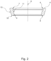
- Figure 2 shows the sealing ring 4 in section.
- the sealing ring 4 is conical in shape to seal the cooling medium and has a first end face 5 and a second end face 6.
- the first end face 5 is subjected to the pressure of the cooling medium and the second end face 6 faces the environment.
- the second end face 6 is assigned a circumferential bead 7 which points in the direction of the longitudinal axis 8 of the sealing ring 4.
- the bead 7 is semicircular and rests against the projection 13 with radial preload.
- a circumferential groove 16 is introduced into the projection 13 to accommodate the sealing ring 4.
- the first end face 5 is inclined at an angle of less than 90° relative to the longitudinal axis 8.
- the first end face 5 has a first edge 9 and a second edge 10, the first edge 9 being subjected to the pressure of the cooling medium.
- the sealing ring 4 has an inner wall 11 and an outer wall 12, wherein the annular surface formed by the first end face 5 encloses an angle of 90° relative to the inner wall 11.
- the annular surface formed by the first end face 5 encloses an angle of 90° relative to the outer wall 12.
- the inner wall 11 is inclined relative to the longitudinal axis 8 by an angle of 15°.
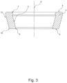
- Figure 3 shows a sealing ring 4 according to Figure 2 , wherein the first end face 5 in the present embodiment runs in a radial plane. In this respect, the annular surface formed by the first end face 5 encloses an angle of 90° with the longitudinal axis 8.
- Figure 4 shows an inventive development of the Figures 1 , 2 and 3 shown arrangement.
- a centering ring 17 is arranged in the annular space 15.
- the centering ring 17 is made of polymer material and is arranged at the free end of the projection 13.
- the centering ring 17 is held in a form-fitting manner on the projection 13.
- the centering ring 17 and the projection 13 have a congruently shaped sawtooth profile.
- the recess 14 is cylindrical in the section assigned to the centering ring 17 and the centering ring 17 is cylindrical on the outer circumference.
- the sealing ring 4 is correspondingly Figure 3
- the projection 13 and the recess 14 have a cylindrical and a conical section, so that the sealing ring 4 This lengthens the permeation path for the medium to be sealed, which improves the tightness of arrangement 1.
- Figure 5 shows a further embodiment of the previously described arrangement 1.
- two bores 18 are made in each of the first coupling element 2 and the second coupling element 3, with opposing bores 18 of the first coupling element 2 and the second coupling element 3 being aligned.
- a pin 19 is arranged in each pair of bores 18, with one pin 19 being fixed to the coupling element 2 and one pin to the second coupling element 3.
Landscapes
- Engineering & Computer Science (AREA)
- General Engineering & Computer Science (AREA)
- Mechanical Engineering (AREA)
- Gasket Seals (AREA)
Priority Applications (5)
| Application Number | Priority Date | Filing Date | Title |
|---|---|---|---|
| PL20202236.4T PL3985293T3 (pl) | 2020-10-16 | 2020-10-16 | Układ do uszczelniania połączenia |
| HUE20202236A HUE067995T2 (hu) | 2020-10-16 | 2020-10-16 | Elrendezés egy összeköttetés letömítésére |
| ES20202236T ES2986451T3 (es) | 2020-10-16 | 2020-10-16 | Disposición para sellar una conexión |
| EP20202236.4A EP3985293B1 (de) | 2020-10-16 | 2020-10-16 | Anordnung zur abdichtung einer verbindung |
| HRP20241130TT HRP20241130T1 (hr) | 2020-10-16 | 2020-10-16 | Sklop za brtvljenje spoja |
Applications Claiming Priority (1)
| Application Number | Priority Date | Filing Date | Title |
|---|---|---|---|
| EP20202236.4A EP3985293B1 (de) | 2020-10-16 | 2020-10-16 | Anordnung zur abdichtung einer verbindung |
Publications (2)
| Publication Number | Publication Date |
|---|---|
| EP3985293A1 EP3985293A1 (de) | 2022-04-20 |
| EP3985293B1 true EP3985293B1 (de) | 2024-06-05 |
Family
ID=73131623
Family Applications (1)
| Application Number | Title | Priority Date | Filing Date |
|---|---|---|---|
| EP20202236.4A Active EP3985293B1 (de) | 2020-10-16 | 2020-10-16 | Anordnung zur abdichtung einer verbindung |
Country Status (5)
| Country | Link |
|---|---|
| EP (1) | EP3985293B1 (es) |
| ES (1) | ES2986451T3 (es) |
| HR (1) | HRP20241130T1 (es) |
| HU (1) | HUE067995T2 (es) |
| PL (1) | PL3985293T3 (es) |
Family Cites Families (6)
| Publication number | Priority date | Publication date | Assignee | Title |
|---|---|---|---|---|
| DE3520949A1 (de) * | 1985-06-12 | 1986-12-18 | Hermann Mücher GmbH & Co KG, 5830 Schwelm | Gleitringdichtung fuer muffenrohrverbindungen |
| DE4231824C2 (de) * | 1992-09-23 | 1994-07-14 | Wagner Gmbh J | Leitungsverbindung |
| DE10261887B4 (de) * | 2002-12-20 | 2005-05-12 | Visteon Global Technologies, Inc., Dearborn | Rohrkupplung |
| DE102006029645B4 (de) * | 2006-06-28 | 2010-02-04 | Hansa Automotive Gmbh & Co. Kg | Kältemittelleitung, insbesondere für mit CO2 betriebene Kraftfahrzeugklimaanlagen |
| DE102007035223A1 (de) | 2007-07-25 | 2009-01-29 | Behr Gmbh & Co. Kg | Dichtungsanordnung |
| US20200200307A1 (en) * | 2018-12-21 | 2020-06-25 | Hanon Systems | Metal seal fitting with tight bend technology |
-
2020
- 2020-10-16 PL PL20202236.4T patent/PL3985293T3/pl unknown
- 2020-10-16 ES ES20202236T patent/ES2986451T3/es active Active
- 2020-10-16 HU HUE20202236A patent/HUE067995T2/hu unknown
- 2020-10-16 EP EP20202236.4A patent/EP3985293B1/de active Active
- 2020-10-16 HR HRP20241130TT patent/HRP20241130T1/hr unknown
Also Published As
| Publication number | Publication date |
|---|---|
| EP3985293A1 (de) | 2022-04-20 |
| ES2986451T3 (es) | 2024-11-11 |
| HUE067995T2 (hu) | 2024-12-28 |
| PL3985293T3 (pl) | 2024-12-16 |
| HRP20241130T1 (hr) | 2024-11-22 |
Similar Documents
| Publication | Publication Date | Title |
|---|---|---|
| DE102021212442B3 (de) | Verfahren zur Herstellung eines Dichtrings | |
| EP2162662B9 (de) | Verbindungsanordnung für eine rohrverschraubung | |
| DE102009034579A1 (de) | Flanschverbindung | |
| EP1445529B1 (de) | Verbindungsanordnung für Kältemittelleitungen | |
| WO2007131468A1 (de) | Dichtungsanordnung zur druckentlastung | |
| EP1873437A2 (de) | Kältemittelleitung, insbesondere für mit CO2 betriebene Kraftfahrzeugklimaanlagen | |
| DE102014105555A1 (de) | Anschlussverbindung für Wellrohre | |
| EP3978751B1 (de) | Verbundmembran für membranpumpen | |
| EP3299788A2 (de) | Flansch-satz für einen differenzdruck-messaufnehmer | |
| DE19507736B4 (de) | Dichtungselement | |
| EP3985293B1 (de) | Anordnung zur abdichtung einer verbindung | |
| DE102023117369A1 (de) | Kugelventil einer Kältemittelventileinrichtung für eine Klimaanlage | |
| EP3246605A1 (de) | Membranventil | |
| WO2008058597A1 (de) | Kupplungsvorrichtung | |
| EP2657583B1 (de) | Drei-fach-exzentrische Absperrarmatur | |
| EP1880135A1 (de) | Verbindungsanordnung für kältemittelleitungen | |
| EP1548348B1 (de) | Dichtungsanordnung, insbesondere für einen Anschluss einer Leitung an einem Expansionsorgan | |
| DE102019111207A1 (de) | Gehäuse | |
| DE19855795B4 (de) | Schneidringverschraubung für Druckmittel-Rohrleitungen | |
| DE102018203445A1 (de) | Dichtungsanordnung und Fluidregelventil | |
| WO2008034519A1 (de) | Ventilanordnung für eine hydrostatische maschine, insbesondere für eine axialkolbenmaschine | |
| DE2655473B2 (de) | Auswinkelbare Flanschverbindung für Rohrleitungen | |
| WO2006077226A1 (de) | Scheibenbremse | |
| WO2002042666A1 (de) | Radialwellendrichtring und dessen verwendung | |
| DE102023118470A1 (de) | Membranventil |
Legal Events
| Date | Code | Title | Description |
|---|---|---|---|
| REG | Reference to a national code |
Ref country code: HR Ref legal event code: TUEP Ref document number: P20241130T Country of ref document: HR |
|
| PUAI | Public reference made under article 153(3) epc to a published international application that has entered the european phase |
Free format text: ORIGINAL CODE: 0009012 |
|
| STAA | Information on the status of an ep patent application or granted ep patent |
Free format text: STATUS: THE APPLICATION HAS BEEN PUBLISHED |
|
| AK | Designated contracting states |
Kind code of ref document: A1 Designated state(s): AL AT BE BG CH CY CZ DE DK EE ES FI FR GB GR HR HU IE IS IT LI LT LU LV MC MK MT NL NO PL PT RO RS SE SI SK SM TR |
|
| RIN1 | Information on inventor provided before grant (corrected) |
Inventor name: WEISS, RAINER Inventor name: WUNDERLE, RAPHAEL Inventor name: KUHNE, DAVID Inventor name: VOEHRINGER, MARC-CHRISTIAN Inventor name: MELCHER, ANDREAS |
|
| STAA | Information on the status of an ep patent application or granted ep patent |
Free format text: STATUS: REQUEST FOR EXAMINATION WAS MADE |
|
| 17P | Request for examination filed |
Effective date: 20221018 |
|
| RBV | Designated contracting states (corrected) |
Designated state(s): AL AT BE BG CH CY CZ DE DK EE ES FI FR GB GR HR HU IE IS IT LI LT LU LV MC MK MT NL NO PL PT RO RS SE SI SK SM TR |
|
| GRAP | Despatch of communication of intention to grant a patent |
Free format text: ORIGINAL CODE: EPIDOSNIGR1 |
|
| STAA | Information on the status of an ep patent application or granted ep patent |
Free format text: STATUS: GRANT OF PATENT IS INTENDED |
|
| INTG | Intention to grant announced |
Effective date: 20240124 |
|
| GRAS | Grant fee paid |
Free format text: ORIGINAL CODE: EPIDOSNIGR3 |
|
| GRAA | (expected) grant |
Free format text: ORIGINAL CODE: 0009210 |
|
| STAA | Information on the status of an ep patent application or granted ep patent |
Free format text: STATUS: THE PATENT HAS BEEN GRANTED |
|
| P01 | Opt-out of the competence of the unified patent court (upc) registered |
Effective date: 20240415 |
|
| AK | Designated contracting states |
Kind code of ref document: B1 Designated state(s): AL AT BE BG CH CY CZ DE DK EE ES FI FR GB GR HR HU IE IS IT LI LT LU LV MC MK MT NL NO PL PT RO RS SE SI SK SM TR |
|
| REG | Reference to a national code |
Ref country code: CH Ref legal event code: EP |
|
| REG | Reference to a national code |
Ref country code: DE Ref legal event code: R096 Ref document number: 502020008188 Country of ref document: DE |
|
| REG | Reference to a national code |
Ref country code: IE Ref legal event code: FG4D Free format text: LANGUAGE OF EP DOCUMENT: GERMAN |
|
| REG | Reference to a national code |
Ref country code: LT Ref legal event code: MG9D |
|
| PG25 | Lapsed in a contracting state [announced via postgrant information from national office to epo] |
Ref country code: BG Free format text: LAPSE BECAUSE OF FAILURE TO SUBMIT A TRANSLATION OF THE DESCRIPTION OR TO PAY THE FEE WITHIN THE PRESCRIBED TIME-LIMIT Effective date: 20240605 |
|
| REG | Reference to a national code |
Ref country code: NL Ref legal event code: MP Effective date: 20240605 Ref country code: SK Ref legal event code: T3 Ref document number: E 44756 Country of ref document: SK |
|
| PG25 | Lapsed in a contracting state [announced via postgrant information from national office to epo] |
Ref country code: FI Free format text: LAPSE BECAUSE OF FAILURE TO SUBMIT A TRANSLATION OF THE DESCRIPTION OR TO PAY THE FEE WITHIN THE PRESCRIBED TIME-LIMIT Effective date: 20240605 |
|
| PG25 | Lapsed in a contracting state [announced via postgrant information from national office to epo] |
Ref country code: GR Free format text: LAPSE BECAUSE OF FAILURE TO SUBMIT A TRANSLATION OF THE DESCRIPTION OR TO PAY THE FEE WITHIN THE PRESCRIBED TIME-LIMIT Effective date: 20240906 |
|
| PG25 | Lapsed in a contracting state [announced via postgrant information from national office to epo] |
Ref country code: LV Free format text: LAPSE BECAUSE OF FAILURE TO SUBMIT A TRANSLATION OF THE DESCRIPTION OR TO PAY THE FEE WITHIN THE PRESCRIBED TIME-LIMIT Effective date: 20240605 |
|
| PG25 | Lapsed in a contracting state [announced via postgrant information from national office to epo] |
Ref country code: NO Free format text: LAPSE BECAUSE OF FAILURE TO SUBMIT A TRANSLATION OF THE DESCRIPTION OR TO PAY THE FEE WITHIN THE PRESCRIBED TIME-LIMIT Effective date: 20240905 Ref country code: LV Free format text: LAPSE BECAUSE OF FAILURE TO SUBMIT A TRANSLATION OF THE DESCRIPTION OR TO PAY THE FEE WITHIN THE PRESCRIBED TIME-LIMIT Effective date: 20240605 Ref country code: GR Free format text: LAPSE BECAUSE OF FAILURE TO SUBMIT A TRANSLATION OF THE DESCRIPTION OR TO PAY THE FEE WITHIN THE PRESCRIBED TIME-LIMIT Effective date: 20240906 Ref country code: FI Free format text: LAPSE BECAUSE OF FAILURE TO SUBMIT A TRANSLATION OF THE DESCRIPTION OR TO PAY THE FEE WITHIN THE PRESCRIBED TIME-LIMIT Effective date: 20240605 Ref country code: BG Free format text: LAPSE BECAUSE OF FAILURE TO SUBMIT A TRANSLATION OF THE DESCRIPTION OR TO PAY THE FEE WITHIN THE PRESCRIBED TIME-LIMIT Effective date: 20240605 Ref country code: RS Free format text: LAPSE BECAUSE OF FAILURE TO SUBMIT A TRANSLATION OF THE DESCRIPTION OR TO PAY THE FEE WITHIN THE PRESCRIBED TIME-LIMIT Effective date: 20240905 |
|
| REG | Reference to a national code |
Ref country code: HR Ref legal event code: ODRP Ref document number: P20241130T Country of ref document: HR Payment date: 20240924 Year of fee payment: 5 |
|
| REG | Reference to a national code |
Ref country code: ES Ref legal event code: FG2A Ref document number: 2986451 Country of ref document: ES Kind code of ref document: T3 Effective date: 20241111 |
|
| PG25 | Lapsed in a contracting state [announced via postgrant information from national office to epo] |
Ref country code: NL Free format text: LAPSE BECAUSE OF FAILURE TO SUBMIT A TRANSLATION OF THE DESCRIPTION OR TO PAY THE FEE WITHIN THE PRESCRIBED TIME-LIMIT Effective date: 20240605 |
|
| REG | Reference to a national code |
Ref country code: HR Ref legal event code: T1PR Ref document number: P20241130 Country of ref document: HR |
|
| PG25 | Lapsed in a contracting state [announced via postgrant information from national office to epo] |
Ref country code: NL Free format text: LAPSE BECAUSE OF FAILURE TO SUBMIT A TRANSLATION OF THE DESCRIPTION OR TO PAY THE FEE WITHIN THE PRESCRIBED TIME-LIMIT Effective date: 20240605 |
|
| PG25 | Lapsed in a contracting state [announced via postgrant information from national office to epo] |
Ref country code: PT Free format text: LAPSE BECAUSE OF FAILURE TO SUBMIT A TRANSLATION OF THE DESCRIPTION OR TO PAY THE FEE WITHIN THE PRESCRIBED TIME-LIMIT Effective date: 20241007 |
|
| REG | Reference to a national code |
Ref country code: HU Ref legal event code: AG4A Ref document number: E067995 Country of ref document: HU |
|
| PG25 | Lapsed in a contracting state [announced via postgrant information from national office to epo] |
Ref country code: PT Free format text: LAPSE BECAUSE OF FAILURE TO SUBMIT A TRANSLATION OF THE DESCRIPTION OR TO PAY THE FEE WITHIN THE PRESCRIBED TIME-LIMIT Effective date: 20241007 |
|
| PG25 | Lapsed in a contracting state [announced via postgrant information from national office to epo] |
Ref country code: EE Free format text: LAPSE BECAUSE OF FAILURE TO SUBMIT A TRANSLATION OF THE DESCRIPTION OR TO PAY THE FEE WITHIN THE PRESCRIBED TIME-LIMIT Effective date: 20240605 |
|
| PG25 | Lapsed in a contracting state [announced via postgrant information from national office to epo] |
Ref country code: IS Free format text: LAPSE BECAUSE OF FAILURE TO SUBMIT A TRANSLATION OF THE DESCRIPTION OR TO PAY THE FEE WITHIN THE PRESCRIBED TIME-LIMIT Effective date: 20241005 |
|
| PG25 | Lapsed in a contracting state [announced via postgrant information from national office to epo] |
Ref country code: SM Free format text: LAPSE BECAUSE OF FAILURE TO SUBMIT A TRANSLATION OF THE DESCRIPTION OR TO PAY THE FEE WITHIN THE PRESCRIBED TIME-LIMIT Effective date: 20240605 |
|
| PG25 | Lapsed in a contracting state [announced via postgrant information from national office to epo] |
Ref country code: SM Free format text: LAPSE BECAUSE OF FAILURE TO SUBMIT A TRANSLATION OF THE DESCRIPTION OR TO PAY THE FEE WITHIN THE PRESCRIBED TIME-LIMIT Effective date: 20240605 Ref country code: IS Free format text: LAPSE BECAUSE OF FAILURE TO SUBMIT A TRANSLATION OF THE DESCRIPTION OR TO PAY THE FEE WITHIN THE PRESCRIBED TIME-LIMIT Effective date: 20241005 Ref country code: EE Free format text: LAPSE BECAUSE OF FAILURE TO SUBMIT A TRANSLATION OF THE DESCRIPTION OR TO PAY THE FEE WITHIN THE PRESCRIBED TIME-LIMIT Effective date: 20240605 |
|
| PG25 | Lapsed in a contracting state [announced via postgrant information from national office to epo] |
Ref country code: IT Free format text: LAPSE BECAUSE OF FAILURE TO SUBMIT A TRANSLATION OF THE DESCRIPTION OR TO PAY THE FEE WITHIN THE PRESCRIBED TIME-LIMIT Effective date: 20240605 |
|
| REG | Reference to a national code |
Ref country code: DE Ref legal event code: R097 Ref document number: 502020008188 Country of ref document: DE |
|
| PLBE | No opposition filed within time limit |
Free format text: ORIGINAL CODE: 0009261 |
|
| STAA | Information on the status of an ep patent application or granted ep patent |
Free format text: STATUS: NO OPPOSITION FILED WITHIN TIME LIMIT |
|
| PG25 | Lapsed in a contracting state [announced via postgrant information from national office to epo] |
Ref country code: DK Free format text: LAPSE BECAUSE OF FAILURE TO SUBMIT A TRANSLATION OF THE DESCRIPTION OR TO PAY THE FEE WITHIN THE PRESCRIBED TIME-LIMIT Effective date: 20240605 |
|
| 26N | No opposition filed |
Effective date: 20250306 |
|
| PG25 | Lapsed in a contracting state [announced via postgrant information from national office to epo] |
Ref country code: MC Free format text: LAPSE BECAUSE OF FAILURE TO SUBMIT A TRANSLATION OF THE DESCRIPTION OR TO PAY THE FEE WITHIN THE PRESCRIBED TIME-LIMIT Effective date: 20240605 |
|
| PG25 | Lapsed in a contracting state [announced via postgrant information from national office to epo] |
Ref country code: LU Free format text: LAPSE BECAUSE OF NON-PAYMENT OF DUE FEES Effective date: 20241016 |
|
| PG25 | Lapsed in a contracting state [announced via postgrant information from national office to epo] |
Ref country code: SE Free format text: LAPSE BECAUSE OF FAILURE TO SUBMIT A TRANSLATION OF THE DESCRIPTION OR TO PAY THE FEE WITHIN THE PRESCRIBED TIME-LIMIT Effective date: 20240605 |
|
| PGFP | Annual fee paid to national office [announced via postgrant information from national office to epo] |
Ref country code: HR Payment date: 20250923 Year of fee payment: 6 |
|
| PG25 | Lapsed in a contracting state [announced via postgrant information from national office to epo] |
Ref country code: IE Free format text: LAPSE BECAUSE OF NON-PAYMENT OF DUE FEES Effective date: 20241016 |
|
| PGFP | Annual fee paid to national office [announced via postgrant information from national office to epo] |
Ref country code: CZ Payment date: 20250929 Year of fee payment: 6 |
|
| REG | Reference to a national code |
Ref country code: HR Ref legal event code: ODRP Ref document number: P20241130 Country of ref document: HR Payment date: 20250923 Year of fee payment: 6 |
|
| PGFP | Annual fee paid to national office [announced via postgrant information from national office to epo] |
Ref country code: SK Payment date: 20250930 Year of fee payment: 6 |
|
| REG | Reference to a national code |
Ref country code: CH Ref legal event code: U11 Free format text: ST27 STATUS EVENT CODE: U-0-0-U10-U11 (AS PROVIDED BY THE NATIONAL OFFICE) Effective date: 20251101 |
|
| PGFP | Annual fee paid to national office [announced via postgrant information from national office to epo] |
Ref country code: HU Payment date: 20251009 Year of fee payment: 6 |
|
| PGFP | Annual fee paid to national office [announced via postgrant information from national office to epo] |
Ref country code: DE Payment date: 20251028 Year of fee payment: 6 |
|
| PGFP | Annual fee paid to national office [announced via postgrant information from national office to epo] |
Ref country code: GB Payment date: 20251023 Year of fee payment: 6 |
|
| PGFP | Annual fee paid to national office [announced via postgrant information from national office to epo] |
Ref country code: AT Payment date: 20251020 Year of fee payment: 6 |
|
| PGFP | Annual fee paid to national office [announced via postgrant information from national office to epo] |
Ref country code: FR Payment date: 20251027 Year of fee payment: 6 |
|
| PGFP | Annual fee paid to national office [announced via postgrant information from national office to epo] |
Ref country code: BE Payment date: 20251024 Year of fee payment: 6 |
|
| PGFP | Annual fee paid to national office [announced via postgrant information from national office to epo] |
Ref country code: CH Payment date: 20251101 Year of fee payment: 6 |
|
| PGFP | Annual fee paid to national office [announced via postgrant information from national office to epo] |
Ref country code: PL Payment date: 20250922 Year of fee payment: 6 |
|
| PGFP | Annual fee paid to national office [announced via postgrant information from national office to epo] |
Ref country code: RO Payment date: 20251003 Year of fee payment: 6 |
|
| PG25 | Lapsed in a contracting state [announced via postgrant information from national office to epo] |
Ref country code: CY Free format text: LAPSE BECAUSE OF FAILURE TO SUBMIT A TRANSLATION OF THE DESCRIPTION OR TO PAY THE FEE WITHIN THE PRESCRIBED TIME-LIMIT; INVALID AB INITIO Effective date: 20201016 |
|
| PGFP | Annual fee paid to national office [announced via postgrant information from national office to epo] |
Ref country code: ES Payment date: 20251118 Year of fee payment: 6 |