EP3984469B1 - Probennahmesystem - Google Patents
Probennahmesystem Download PDFInfo
- Publication number
- EP3984469B1 EP3984469B1 EP20822627.4A EP20822627A EP3984469B1 EP 3984469 B1 EP3984469 B1 EP 3984469B1 EP 20822627 A EP20822627 A EP 20822627A EP 3984469 B1 EP3984469 B1 EP 3984469B1
- Authority
- EP
- European Patent Office
- Prior art keywords
- gas
- liquid
- tube
- sampling
- control unit
- Prior art date
- Legal status (The legal status is an assumption and is not a legal conclusion. Google has not performed a legal analysis and makes no representation as to the accuracy of the status listed.)
- Active
Links
Images


Classifications
-
- A—HUMAN NECESSITIES
- A61—MEDICAL OR VETERINARY SCIENCE; HYGIENE
- A61B—DIAGNOSIS; SURGERY; IDENTIFICATION
- A61B10/00—Instruments for taking body samples for diagnostic purposes; Other methods or instruments for diagnosis, e.g. for vaccination diagnosis, sex determination or ovulation-period determination; Throat striking implements
- A61B10/02—Instruments for taking cell samples or for biopsy
- A61B10/04—Endoscopic instruments, e.g. catheter-type instruments
-
- A—HUMAN NECESSITIES
- A61—MEDICAL OR VETERINARY SCIENCE; HYGIENE
- A61B—DIAGNOSIS; SURGERY; IDENTIFICATION
- A61B10/00—Instruments for taking body samples for diagnostic purposes; Other methods or instruments for diagnosis, e.g. for vaccination diagnosis, sex determination or ovulation-period determination; Throat striking implements
- A61B10/02—Instruments for taking cell samples or for biopsy
- A61B10/06—Biopsy forceps, e.g. with cup-shaped jaws
-
- A—HUMAN NECESSITIES
- A61—MEDICAL OR VETERINARY SCIENCE; HYGIENE
- A61B—DIAGNOSIS; SURGERY; IDENTIFICATION
- A61B18/00—Surgical instruments, devices or methods for transferring non-mechanical forms of energy to or from the body
- A61B18/04—Surgical instruments, devices or methods for transferring non-mechanical forms of energy to or from the body by heating
- A61B18/08—Surgical instruments, devices or methods for transferring non-mechanical forms of energy to or from the body by heating by means of electrically-heated probes
- A61B18/082—Probes or electrodes therefor
-
- A—HUMAN NECESSITIES
- A61—MEDICAL OR VETERINARY SCIENCE; HYGIENE
- A61B—DIAGNOSIS; SURGERY; IDENTIFICATION
- A61B10/00—Instruments for taking body samples for diagnostic purposes; Other methods or instruments for diagnosis, e.g. for vaccination diagnosis, sex determination or ovulation-period determination; Throat striking implements
- A61B10/02—Instruments for taking cell samples or for biopsy
- A61B2010/0208—Biopsy devices with actuators, e.g. with triggered spring mechanisms
Definitions
- Embodiments of the present disclosure relates to the technical field of medical devices, and particularly to a sampling system.
- Endoscopy is an approach to obtain the type of lesion in a human body, which includes sampling a tissue in the human body by a sampling system to obtain a tissue sample and then examining the tissue sample to determine the type of lesion in a lesion site in the human body.
- a surgeon delivers the sampling system into a lesion site in a human body, acquires a sample from the tissue in the lesion site in the human body by an acquiring device on the sampling system to obtain a tissue sample, and examines the tissue sample, to acquire the cause and type of lesion in the lesion site in the human body.
- US 2002/169362 A1 discloses an operating instrument insertion apparatus capable of easily inserting an operating instrument into the tissue.
- the operating instrument insertion apparatus includes a hollow tubular member for receiving an operating instrument therein, and a plurality of scoop-like members provided at a distal end of the hollow tubular member.
- the plurality of scoop-like members can be opened in such a manner that distal ends of the scoop-like members are moved away from each other in a direction transverse to an axial direction of said hollow tubular member, and the plurality of scoop-like members can be closed in such a manner that the distal ends of the scoop-like members are moved toward each other in this transverse direction, wherein the scoop-shape members in the opened condition cooperate so that an outside diameter formed thereby is no greater than an outside diameter of the hollow tube member.
- JP H11-019086 A discloses that: a fulcrum shaft is bridged to a distal side of a supporting piece of a supporting utensil which is fixed to a distal end of a sheath. On the fulcrum shaft, link pieces of forceps pieces are turnably fitted, and an insulating spacer is fitted in a space between the link pieces. To the link pieces, other link pieces are connected under a pantograph state, and to the rear ends of the link pieces, a distal end of a longitudinal member, which can advance or retract in the longitudinal direction X along a lumen in the sheath, is connected.
- the forceps pieces are turnably fitted in the fulcrum shaft in such a manner that cup- shaped recesses may be confronted to each other, and electrodes are formed at the tip end side edges of the recesses of the forceps pieces, and a distal end ofa conductive wire is electrically connected.
- US 5,217,458 A discloses a bipolar biopsy device for removing tissue samples for biopsy purposes or other purposes.
- the bipolar biopsy device has an elongated flexible end and a lumen extending therebetween.
- a cutting head is mounted on the distal end and has a hollow fixed member containing an electrode having an electrical surface thereon and a hollow cup-shaped moveable relative to the fixed member.
- the electrode surfaces are electrically connected to an outside voltage source.
- a handle is affixed to the proximal end and a core wire is affixed to the handle which extends through the lumen and is affixed to the movable hollow cup-shaped member.
- the core wire manipulated by way of the handle facilitates the movement of the movable cup-shaped member.
- Tissue samples are obtained by positioning the electrode surfaces close to each other about the tissue sample. An arc is created to break tissue down by applying a voltage to the electrode surfaces. The cut tissue remains within the cup-shaped members as the device is withdrawn from the body for later biopsy purposes
- US 5,133,360 A discloses a biopsy instrument which has a retractable cutting wire or filament looped external to the innermost surface of the distal end of the tissue cutting cylinder. Forceful retraction of the cutting wire will cause displacement and closure of a loop of wire over the distal margin of the cored tissue biopsy, thus freeing the biopsy specimen in its entirety from its original locus and allowing removal of the entire cored biopsy from the body substantially without stretching the specimen along its length.
- US 5,848,978 A discloses a surgical core biopsy apparatus, having a hollow elongated member with an axis and a leading end, a sharpened edge at a portion of the leading end for cutting tissue along the axis, an actuator, and a cutting edge, linked to the actuator, being movable along a path including a transverse component to the axis, effective for severing tissue along an the path.
- the path is preferably an arcuate path, the cutting device being pivoted about an axis transverse to the axis of said hollow elongated member at said leading end.
- the actuator preferably acts by way of a compression force transmitted along the axis by a compression member, from a handle portion to the cutting edge.
- the elongated member is preferably a tube having two or more lumens, a first large centrally located lumen for accommodating a tissue core sample, and at least one other eccentrically located rectangular cross section lumen containing the compression member.
- the biopsy apparatus may be used, for example, to obtain a percutaneous excision breast biopsy from a tumor whose location is marked with a radiopaque guide wire.
- US 2005/113854 A1 discloses a surgical instrument for removal of a conical section the cervix for pathological examination is disclosed.
- the device includes a circular knife having a plurality of double-edged blades, the edges of adjacent blades enclosing against one another when the device is operated from unengaged to engaged positions.
- a hollow plunger is further disclosed used to actuate the circular knife.
- Novel pivot devices are additionally included to provide translational movement of the hollow plunger bar.
- a pronged stabilization rod is disclosed to prevent the circular knife from moving away from the target tissue during a cutting stroke.
- the device is an improvement over prior devices and procedures in that it provides a precision conical tissue sample ideal for analysis with minimal resulting bleeding.
- WO 2019/103694 A1 discloses a balloon-anchored biopsy device.
- the sampling device on the sampling system is usually forceps or needle aspiration.
- the sample is often too shallow and/or small when the tissue sample is repeatedly taken by forceps or by needle aspiration; and if large-size and deep sampling (such as cryobiopsy) is adopted, significant bleeding is often caused, and the operation is not safe and reliable.
- the object of the embodiments of the present application is to provide a sampling system with safe and reliable operation.
- a sampling system which includes:
- the sampling unit comprises a sampling sheath, a support portion and a heating member, wherein one end of the sampling sheath inserts into the connecting tube and connected to the connecting tube, and an other end of the sampling sheath is connected to the support portion; the support portion is deformable upon an external force, and the heating member is mounted around the sampling sheath; and the one end of the actuating string is fixed to the first adjustment knob and the other end of the actuating string is fixed to the heating member; the actuating string is controllable to move by controlling the first adjustment knob, whereby the heating member is controlled to be opened or closed, which in turn drives the support portion to be opened or closed.
- the connecting tube comprises a communicating tube, having at least one end extending through the control unit, wherein the one end of the sampling sheath inserts into the communicating tube and is connected to the communicating tube; and the communicating tube is provided with a receiving passage and an aperture, wherein the aperture is located in the control unit.
- control unit comprises a conductive component having a cable sheath and a cable, wherein the cable sheath is fixedly mounted in the control unit, and the cable is partly located in the cable sheath and partly in the receiving passage, and the cable has one end electrically connected to the outside and an other end extending through the aperture and the receiving passage and electrically connected to the heating member.
- the connecting tube further comprises an endoscope tube and an outer sleeve, wherein
- the connecting tube further comprises a gas-liquid tube located between the outer sleeve and the communicating tube, and both the balloon and the metal ring are mounted around one end of the gas-liquid tube adjacent to the sampling unit.
- control unit further comprises a linear rack and a second adjustment assembly
- control unit further comprises a conducting assembly having a balloon gas-liquid joint, wherein the balloon gas-liquid joint is communicated with the gas-liquid tube, and the balloon gas-liquid joint is provided with a balloon gas-liquid exchange port thereon;
- the conducting assembly further comprises a body gas-liquid joint, wherein the body gas-liquid joint is connected to the gas-liquid tube, and the body gas-liquid joint is provided with a body gas-liquid exchange port thereon;
- Embodiments of the present application have the following beneficial effects.
- the control unit and the sampling unit are connected through a connecting tube, the control unit is provided with a first adjustment assembly, and the first adjustment assembly includes a first adjustment knob and an actuating string. Two ends of the actuating string are respectively connected to the first adjustment knob and the sampling unit. Due to the rigidity and high hardness of the actuating string, by controlling the first adjustment knob, the movement of the actuating string is controlled to be pulled or loosened, so that the sampling unit can be opened and closed to enable the cutting and acquisition by sampling unit with safe and reliable operations.
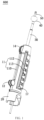
- an embodiment of the present application provides a sampling system 600, which includes a control unit 10, an endoscope connecting seat 20, a connecting tube 30, a balloon unit 40 and a sampling unit 50.
- the control unit 10 is fixedly connected to the endoscope connecting seat 20.
- the connecting tube 30 has one end extending through the control unit 10 and is assembled thereto.
- the sampling unit 50 and the balloon unit 40 are both fixedly assembled to the connecting tube 30.
- the sampling unit 50 is located at one end of the connecting tube 30.
- the balloon unit 40 is located between the sampling unit 50 and the control unit 10.
- the sampling unit 50 and the balloon unit 40 is opposite to one end of the control unit 10, and the endoscope connecting seat 20 is located at the other end of control unit 10.
- the control unit 10 is configured to adjust and control the working state and working position of the sampling unit 50 and the balloon unit 40.
- the control unit 10 includes a housing 11, a first adjustment assembly 12, a linear rack 13, a second adjustment assembly 14, a balloon buffering assembly 15, a conductive component 16, a locking fin 17, and a conducting assembly 18.
- the linear rack 13 is located inside the housing 11.
- the first adjustment assembly 12, the second adjustment assembly 14, the conductive component 16, the locking fin 17, the conducting assembly 18 and the balloon buffering assembly 15 are all partially located inside the housing 11 and partly located outside the housing 11.
- the housing 11 is configured for installing and accommodating other parts of the control unit 10.
- the housing 11 can be made of a plastic material, which has a light weight and prevents electric leakage.
- the housing 11 is substantially cylindrical with a chamfer at one end. Both ends of the housing 11 are each provided with an opening.
- the housing has a hollow structure inside for partially accommodating other parts of the control unit 10 and partially accommodating the connecting tube 30.
- the housing 11 is provided with a first opening 110, a second opening 111, a third opening 112, at least one clamping position 113 and at least one blocking wall 114.
- the first opening 110, the second opening 111, the third opening 112 and the clamping position 113 all penetrate the housing 11.
- the first opening 110, the second opening 111, and the third opening 112 are all rectangular holes; and the first opening 110, the second opening 111 and the third opening 112 all extend along the length direction of the housing 11.
- the at least one clamping position 113 is located at one side of the third opening 112, and includes a plurality of clamping positions 113.
- the plurality of clamping positions 113 are arranged side by side along the longitudinal direction of the third opening 112, and communicated with the third opening 112.
- the at least one blocking wall 114 is located inside the housing 11.
- two blocking walls 114 are provided, and the two blocking walls 114 are located at two ends of the housing 11 respectively.
- One end of the housing 11 is assembled with the endoscope connecting seat 20.
- the housing 11 and the endoscope connecting seat 20 can be assembled by welding, or by threaded connection via a threaded hole.
- the endoscope connecting seat 20 is configured for mounting to other parts of the sampling system 600, so as to connect the housing 11 and other parts of the sampling system 600.
- the first adjustment assembly 12 is used to control the opening and closing of the sampling unit 50, and includes at least one first adjustment knob 120, at least one actuating string 122, and a connecting block 121, wherein two first adjustment knobs 120 are provided, and two actuating strings are provided correspondingly.
- the two first adjustment knobs 120 are both fitted to the connecting block 121, and are respectively located at two sides of the connecting block 121.
- the two first adjustment knobs 120 can rotate relative to the connecting block 121.
- the connecting block 121 is in contact with and connected to the connecting tube 30.
- the two actuating strings 122 are respectively fitted to the two first adjustment knobs 120.
- the controlling of the opening and closing of the sampling unit 50 can be achieved by rotating the two first adjustment knobs 120.
- the sampling unit 50 is opened.
- the sampling unit 50 is closed.
- the end of the actuating string 122 that is fitted to the sampling unit 50 is Y-shaped, and is fitted to the sampling unit 50 by welding or clamping.
- the linear rack 13 is located inside the housing 11, and a portion of the connecting tube 30 is located inside the housing 11.
- the linear rack 13 is fixedly assembled with the portion of the connecting tube 30 located inside the housing 11. Further, the linear rack 13 is arranged along the length direction of and parallel to the connecting tube 30.
- the second adjustment assembly 14 is configured to control the working positions of the sampling unit 50 and the balloon unit 40, and includes a second adjustment knob 140 and a third adjustment gear 141.
- the outer diameter of the second adjustment knob 140 is larger than that of the third adjustment gear 141, and the second adjustment knob 140 is assembled with the third adjustment gear 141.
- the second adjustment knob 140 and the third adjustment gear 141 may be connected by a connecting rod.
- the second adjustment knob 140 and the third adjustment gear 141 may be assembled in other ways.
- the third adjustment gear 141 and the linear rack 13 are engaged with each other. When the second adjustment knob 140 is rotated, the third adjustment gear 141 is driven to rotate, thereby driving the linear rack 13 and the connecting tube 30 to move.
- the balloon buffering assembly 15 is configured for assembly with an external structure during use, to fix the sampling system, or to stabilize the entire sampling system.
- the balloon buffering assembly 15 includes a magnetic damper 150, a mounting block 151, and at least one spring 152.
- the magnetic damper 150 is assembled with the spring 152 and the mounting block 151, to compensate incidentally moving of the balloon unit 40 and the connecting tube 30, thus ensuring the balance of the entire sampling system 600.
- the magnetic damper 150 is in the form of a rectangular block structure, and the mounting block 151 is T-shaped.
- the magnetic damper 150 and the spring 152 are located inside the housing 11, and the mounting block 151 extends through the second opening 111 and is then fixedly assembled with the magnetic damper 150 located inside the housing 11.
- the magnetic damper 150 and the mounting block 151 may be assembled by punching and screwing, or by other means.
- each spring 152 has one end abutting against the magnetic damper 150, and the other end abutting against the blocking wall 114.
- the housing 11 is further provided with a positioning member (not shown).
- the positioning member is located on the outer surface of the housing 11, and is fixed to the housing 11 and assembled with the balloon buffering assembly 15.
- the positioning member is also provided with an opening at a position aligned with the second opening 111.
- the mounting block 151 is partially extended through the opening in the positioning member and the second opening 111 and then fixedly assembled with the magnetic damper 150.
- the mounting block 151 is moveable relative to the positioning member.
- the positioning member has a reinforced connection and limiting function for the balloon buffering assembly 15.
- the positioning member may be omitted.
- a plate-shaped wall of the housing 11 serves as a limiting wall (not shown), and the limiting wall together with another curved wall connected thereto defines a triangular receiving space.
- a cable 161 is partially received in the receiving space to prevent the cable 161 and other parts in the housing 11 from being in a mess.
- the conductive component 16 includes a cable sheath160 and the cable 161.
- the limiting wall can be omitted.
- the cable sheath 160 has a hollow structure with two open ends, and is installed in the housing 11.
- the cable 161 is partially coiled in the cable sheath 160, and the cable sheath 160 is used to prevent the cable 161 located in the housing 11 from being in a mess.
- One end of the cable 161 is electrically connected to an external circuit system, and the other end is connected to the sampling unit 50.
- the sampling unit 50 is electrically connected to a circuit and electrically conducted by the cable 16.
- the tissues and blood vessels will inevitably be harmed, and the coagulation of blood can be accelerated by the conduction and heating of the sampling unit 50, to control the bleeding, and ensure the safety of the sampling process.
- One end of the cable 161 is electrically connected to an external circuit, and the other end extends through the connecting tube 30 to reach the sampling unit 50.
- a hole for running the cable 161 is provided in the connecting tube 30. The cable 161 runs through the hole in the connecting tube 30 to reach and be electrically connected to the sampling unit 50.
- the locking fin 17 is fixedly assembled with the connecting tube 30, and used to clamped with the clamping position 113 of the housing 11.
- the locking fin 17 includes a fixing portion 170 and an engaging portion 171, with an obtuse angle formed therebetween. This arrangement avoids the interference of the locking fin 17 with the movement of the connecting tube 30, and facilitates the clamping between the locking fin 17 and the clamping position 113.
- the fixing portion 170 is provided with a fixing hole 172.
- the fixing hole 172 extends from one side of the fixing portion 170 toward the clamping portion 171, and has a semicircular shape.
- the fixing hole 172 is configured for fixedly assembly with the connecting tube 30.
- the fixing portion 170 is mounted around and tightly fitted with the connecting tube 30 via the fixing hole 172. In this manner, the fixing portion 170 is fixed to the connecting tube 30, and accordingly the locking fin 17 is fixed to the connecting tube 30, so that when the locking fin 17 moves, it can drive the connecting tube 30 to move.
- the fixing portion 170 is mounted around the connecting tube 30 via the fixing hole 172, and the fixing portion 170 restricts the position of the locking fin 17 with respect to the connecting tube 30 by at least one elastic retainer ring.
- Two elastic retainer rings are provided, which are respectively located at upper and lower ends of the fixing portion 170 to fix the locking fin 17 and the connecting tube 30.
- the clamping portion 171 is configured to fit with the clamping position 113 to limit the position of the connecting tube 30 with respect to the housing 11, that is, to limit the working positions of the sampling unit 50 and the balloon unit 40 with respect to the housing 11.
- the clamping portion 171 is clamped at the clamping position 113, to restrict and fix the connecting tube 30.
- the connecting tube 30 will not move due to an external force, thereby restricting and fixing the working position of the balloon unit 40.
- the conducting assembly 18 includes a body gas-liquid joint 180, a balloon gas-liquid joint 181, and a gas-liquid tube connecting portion 182.
- the body gas-liquid joint 180 communicates with the internal environment of the human body, and the gas and liquid in the body is exported to an external environment by the body gas-liquid joint 180.
- the balloon gas-liquid joint 181 communicates with the balloon unit, and the gas and liquid in the balloon unit 40 is exported to an external environment by the balloon gas-liquid joint 181.
- the gas-liquid tube connecting portion 182 is used to store part of the gas and liquid from the body and the balloon unit.
- the gas-liquid tube connecting portion 182 is fixedly connected to the connecting tube 30, and communicated with the connecting tube 30.
- the gas-liquid tube connecting portion 182 and the connecting tube 30 are provided with holes, via which they communicated with each other.
- the human body and the balloon unit 40 are communicated by the connecting tube 30.
- the gas-liquid tube connecting portion 182 is provided with a storage cavity (not shown).
- the storage cavity is optionally divided into two separate parts that are respectively in communication with the gas-liquid joint 180 and the balloon gas-liquid joint 181.
- a part of the gas-liquid tube connecting portion 182 receives the gas and liquid introduced from the body, and the other part receives the gas and liquid introduced from the balloon unit 40.
- the gas-liquid tube connecting portion 182 is further provided with at least one first gas-liquid vent (not shown) and at least one second gas-liquid vent (not shown).
- two first gas-liquid vents and two second gas-liquid vents are provided.
- the two first gas-liquid vents and the two second gas-liquid vents are located separately at two separate parts of the gas-liquid tube connecting portion 182.
- the connecting tube 30 and the gas-liquid tube connecting portion 182 are communicated by one of the first gas-liquid vents, and the gas-liquid tube connecting portion 182 and the body gas-liquid joint 180 are communicated by the other of the first gas-liquid vent, to enable gas and liquid conduction.
- the connecting tube 30 and the gas-liquid tube connecting portion 182 are communicated by one of the second gas-liquid vents, and the gas-liquid tube connecting portion 182 and the balloon gas-liquid joint 181 are communicated by the other of the second gas-liquid vents, to achieve gas and liquid conduction.
- the body gas-liquid joint 180 is provided with a body gas-liquid exchange port (not shown) correspondingly, and the body gas-liquid exchange port communicates with the two first gas-liquid vents.
- the body gas-liquid exchange port By the body gas-liquid exchange port, the gas and liquid in the body are allowed to flow to the external environment, or the gas and liquid in the external environment is allowed to be introduced into the body.
- the balloon gas-liquid joint 181 is provided with a balloon gas-liquid exchange port (not shown) correspondingly, and the balloon gas-liquid exchange port communicates with the two second gas-liquid vents.
- the balloon gas-liquid exchange port By the balloon gas-liquid exchange port, the gas and liquid in the balloon unit 40 are allowed to be introduced to the external environment, or the gas and liquid in the external environment is allowed to be introduced into the balloon unit 40.
- the balloon gas-liquid exchange port may be connected, by a tube, to an external device, for example, an oxygen supply device or a ventilation device.
- a thin tube (not shown) is provided in the gas-liquid tube connecting portion 182 and the connecting tube 30.
- the thin tube has a hollow tubular structure with two open ends.
- the connecting tube 30 and the gas-liquid tube connecting portion 182 are provided with a hole for the thin tube extending through.
- the thin tube is partly located in the connecting tube 30, and partly located in the gas-liquid tube connecting portion 182. The thin tube allows the liquid and gas to flow between the connecting tube 30 and the gas-liquid tube connecting portion 182.
- the connecting tube 30 is made of a transparent material and includes an outer sheath 31, a gas-liquid tube 32, a communicating tube 33 and an endoscope tube 34.
- the outer sheath 31 is located at the outermost side, and the endoscope tube 34 is located at the innermost side.
- the gas-liquid tube 32 and the communicating tube 33 are located between the outer sheath 31 and the endoscope tube 34.
- the gas-liquid tube 32 is closer to the outer sheath 31 than the communicating tube 33
- the communicating tube 33 is closer to the endoscope tube 34 than the gas-liquid tube 32.
- the length of the outer sheath 31 is shorter than those of the gas-liquid tube 32 and the communicating tube 33.
- the outer sheath 31 protects other tubes inside, and one end of the outer sheath 31 is fixed to one end of the housing 11.
- the gas-liquid tube 32 is used to conduct the liquid and gas.
- the gas-liquid tube 32 communicates with the gas-liquid tube connecting portion 182 of the conducting assembly 18.
- the gas-liquid tube 32 is provided with a first gas-liquid guide hole (not shown) and a second gas-liquid guide hole (not shown).
- the center line of the first gas-liquid guide hole is parallel to the center line of the second gas-liquid guide hole.
- the first gas-liquid guide hole communicates with the two first gas-liquid vents, and the first gas-liquid guide hole communicates with the balloon gas-liquid exchange port.
- the second gas-liquid guide hole communicates with the two second gas-liquid vents, and the second gas-liquid guide hole communicates with the body gas-liquid exchange port.
- the communicating tube 33 is used to lead the actuating string 122 and the cable 161 to the sampling unit 50, so that the actuating string 122 can be assembled with the sampling unit 50, and the cable 161 and the sampling unit 50 can be electrically connected.
- the linear rack 13 is fixedly assembled with the communicating tube 33, and engaged with the third adjustment gear 141 of the second adjustment assembly 14. By rotating the second adjustment knob 140, the third adjustment gear 141 and the linear rack 13 interact with each other to drive the communicating tube 33 to move.
- a plurality of receiving passages (not shown) and a plurality of apertures (not shown) are provided in the communicating tube 33.
- the plurality of receiving passages are used to receive the actuating string 122 and the cable 161, and the plurality of apertures are configured for the actuating string 122 and the cable 161 extending through, to realize the connection of the actuating string 122 and the cable 161 to the sampling unit 50.
- the endoscope tube 34 is actually a part of an endoscope, and has one end equipped with a camera device for taking pictures of the environment in the body, so that the physician can judge the sampling state and the condition in the body.
- the endoscope tube 34 can move relative to the control unit 10. Specifically, the endoscope tube 34 can move relative to the housing 11 to take pictures of the environment in the body.
- the balloon unit 40 includes a balloon 41 and a metal ring 42.
- the balloon 41 is made of a plastic material with an elastic deformation characteristic, and used to accommodate a gas and liquid.
- the metal ring 42 is used to prompt or indicate the position of the balloon 41.
- the balloon 41 and the metal ring 42 are both mounted around the gas-liquid tube 32 at one end close to the sampling unit 50, without communicating with the balloon gas-liquid joint 181 and the body gas-liquid joint 180.
- the metal ring 42 is mounted around the gas-liquid tube 32, and the gas-liquid tube 32 is provided with a first gas-liquid acquiring hole (not shown) at a position corresponding to the first gas-liquid guide hole.
- the gas and liquid in the balloon 41 flow in from the first gas-liquid acquiring hole of the gas-liquid tube 32, and flow to the balloon gas-liquid exchange port via the first gas-liquid guide hole and the two first gas-liquid vents in sequence and finally to the external environment or to the other device connected to the balloon gas-liquid joint 181.
- the gas and liquid can flow into the balloon unit 40 from a reverse direction.
- the gas and liquid in the body flow in from the second gas-liquid guide hole, and flow to body gas-liquid exchange port via the two second gas-liquid vents and finally to the external environment.
- the gas and liquid can flow into the body from a reverse direction.
- the fixing portion 170 is mounted around the gas-liquid tube 32 through the fixing hole 172, and closely fits with the gas-liquid tube 32, to fix the fixing portion 170 and the gas-liquid tube 32. That is, the locking fin 17 and the gas-liquid tube 32 are fixed, so that the gas-liquid tube 32 can temporarily lock the positions of the balloon 41 and the gas-liquid tube 32 before the balloon 41 expands. After the balloon 41 expands, the locking of the position of the locking fin 17 can be released.
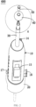
- the sampling unit 50 includes a sampling sheath 51, a support portion 52, a heating member 53 and at least one support bar 54.
- the sampling sheath 51 is mounted around the endoscope tube 34 and assembled with the endoscope tube 34. Moreover, the sampling sheath 51 is made of a relatively hard material, and used to install the support portion 52, to support and protect the support portion 52.
- the support portion 52 is a plastic molded member that is deformable by an external force, and is made of a plastic material with a certain hardness.
- the support portion 52 includes two parts, which are located on two sides of the same end of the sampling sheath 51.
- Two support bars 54 are provided, and the two support bars 54 are respectively assembled with the two parts of the support portion 52, to support the support portion 52, so that the support portion 52 can maintain its shape after being expanded.
- the heating member 53 is mounted around the support portion 52.
- a part of the heating member 53 is inserted and fixed in the sampling sheath 51, and the other part is mounted around the support portion 52.
- the heating member 53 also includes two parts.
- the two parts of the heating member 53 are respectively mounted around the outer surfaces of the two parts of the support portion 52.
- the two parts of the heating member 53 are fixedly assembled with the actuating strings 122, and the entire heating member 53 is opened and closed by controlling the movement of the actuating strings 122.
- the heating member 53 is a heating coil, and the heating coil includes two parts.
- the two parts of the heating coil are respectively mounted around the two parts of the support portion 52.
- the two parts of the heating coil are deformable upon an external force. Normally, the two parts of the heating coil are wound into a cylindrical shape.
- One end of the actuating string 122 is assembled with the ends of the two parts of the heating coil that is away from the sampling sheath 51.
- one end of the actuating string 122 is assembled with the ends of the heating coil away from the sampling sheath 51 by hooking.
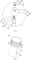
- the actuating string 122 When the first adjustment knob 120 is rotated clockwise, the actuating string 122 is pulled. The two parts of the heating coil are pulled, such that the entire heating member 53 is in a hemispheric shape (as shown in FIG. 8 ), the heating member 53 is closed, and the heating member 53 drives the support portion 52 to close at the same time.
- the actuating string 122 When the first adjustment knob 120 is rotated counterclockwise, the actuating string 122 is loosened, and without a pulling force, the two parts of the heating coil is unstressed, and returns to a cylindrical shape (as shown in FIG. 7 ). As a result, the heating member 53 opens, and the heating member 53 drives the support portion 52 to open.
- the heating member 53 When the heating member 53 is opened and closed, it drives the support portion 52 to open and close.
- the heating member 53 is connected to the cable 161 to realize electrical connection with an external circuit and realize heat generation. In this manner, the bleeding can be controlled, ensuring the safety of the sampling process.
- the heating member 53 instead of the support portion 52, that is used to cut the tissue.
- the support portion 52 is used to support the heating member 53, to prevent the heating member 53 from being in a mess, and serves to collect the tissues cut by the heating member 53.
- the support portion 52 is a plastic molded member. One end of the support portion 52 is fixedly assembled with the sampling sheath 51.
- the support portion 52 is electrically insulating and has a cylindrical shape. The end of the support portion 52 away from the sampling sheath 51 is cut to form a plurality of tongues 521, and the tongues 521 are electrically insulating.
- the heating member 53 includes a first heating portion 531 and a second heating portion 532.
- the first heating portion 531 is similar in shape to the support portion 52, and is mounted around the outer surface of the support portion 52.
- the second heating portion 532 is embedded in the tongue 521.
- the actuating string 122 is in the form of a lasso.
- the actuating string 122 is partially embedded in the support portion 52, and the portion of the actuating string 122 embedded in the support portion 52 is annular. A portion of the actuating string 122 runs along the connecting tube 30 through the support portion 52, and extends to the first adjustment assembly 12 for assembly with the first adjustment knob 120.
- the support bar 54 may not be rigid.
- the actuating string 122 When the first adjustment knob 120 is rotated clockwise, the actuating string 122 is pulled, and the tongues 521 on the support portion 52 are pulled at the same time. The tongues 521 are bent in the same direction, so that the entire support portion 52 is in a closed state.
- the actuating string 122 When the first adjustment knob 120 is rotated counterclockwise, the actuating string 122 is unstressed, so that the tongues 521 are subjected to no force, and thus returns to its initial shape, and slowly becomes straight, making the entire support portion 52 in an open state.
- a non-thermal conductive layer (not shown) is provided between the first heating portion 531 and the sampling sheath 51 to separate the sampling sheath 51 and the first heating portion 531 to protect the sampling sheath 51 against influence by the first heating portion 531.
- the sampling unit 50 does not include the sampling sheath 51, the support portion 52, the heating member 53 and the support bar 54. Instead, the sampling unit 50 includes an outer ring 55, an inner ring 56, at least one heating piece 57, at least one metal strip 58, and an insulating layer 59.
- the outer ring 55 and the inner ring 56 are both connected to the communicating tube 33, and the outer ring 55 and the inner ring 56 are both rotatable relative to the communicating tube 33.
- the communicating tube 33, the outer ring 55 and the inner ring 56 are provided with a receiving passage (not shown) for receiving the actuating string 122.
- the outer ring 55 and the inner ring 56 each have a hollow cylindrical shape with two open ends.
- the outer ring 55 and the inner ring 56 each are further provided with an annular tube (not shown) respectively at the end away from the communicating tube 33.
- the receiving passages are perpendicular to the annular tubes.
- One end of the actuating string runs through the communicating tube 33, and the receiving passages of the outer ring 55 and the inner ring 56, and is then fixed in the annular tubes.
- the annular tubes of the outer ring 55 and the inner ring 56 each are provided with an opening (not shown).
- two actuating strings 122 are provided, which are respectively an outer ring actuating string and an inner ring actuating string.
- the sampling system 600 is provided with a gear (not shown) for controlling the actuating string.
- Two gears are provided, which are both installed on the control unit 10, and are respectively an outer ring gear and an inner ring gear.
- the outer ring gear is used to control the state of the outer ring actuating string.
- the outer ring actuating string surrounds the outer ring gear, and two ends of the outer ring actuating string respectively pass through the receiving passage and enter the annular tube from the opening of the annular tube of the outer ring.
- the two ends enter the annular tube in two opposite directions, and are both fixed in the annular tube so that the portion of the outer ring actuating string located in the annular tube is ring-shaped.
- the inner ring gear is used to control the state of the inner ring actuating string.
- the inner ring actuating string surrounds the inner ring gear, and two ends of the inner ring actuating string respectively pass through the receiving passage and enter the annular tube from the opening of the annular tube of the inner ring.
- the two ends enter the annular tube in two opposite directions, and are both fixed in the annular tube so that the portion of the inner ring actuating string located in the annular tube is ring-shaped.
- the positions of two portions of the actuating string respectively on two sides of the inner ring gear is controlled, to control the positions of the two ends of the inner ring actuating string, so as to rotate the outer ring 56.
- the inner ring gear can be driven to rotate in an opposite direction. Therefore, in this embodiment, the inner ring gear and the outer ring gear rotate in opposite directions.
- heating piece 57 is fixed to one end of the outer ring 55, and one end of the metal strip 58 is fixed to one end of the inner ring 56.
- the six heating pieces 57 and six metal strips 58 are provided, and the six heating pieces 57 and six metal strips 58 are annularly arranged.
- other number of heating pieces 57 and metal strips 58 can be provided, which are not limited herein.
- the sampling unit 50 also includes a fastener (not shown).
- a fastener (not shown).
- six fasteners are provided.
- Each heating piece 57 and one corresponding metal strip 58 are fixedly connected by one fastener.
- the heating piece 57 and the metal strip 58 are rotatable, and the fastener is located on an end of the heating piece 57 away from the outer ring 55.
- the insulating layer 59 is mounted on the metal strip 58 to provide insulation and protection.
- an air insulating layer is provided between the heating piece 57 and the metal strip 58.
- the outer ring gear and the inner ring gear are rotated, and the outer ring 55 and the inner ring 56 are driven to move by controlling the rotation positions of the two ends of the outer ring actuating string and the inner ring actuating string.
- the heating piece 57 and the metal strip 58 are driven to rotate in opposite directions.
- the heating piece 57 and the metal strip 58 are fixed by the fastener, so that the heating piece 57 and the metal strip 58 are bent.
- the heating piece 57 and the metal strip 58 are both bent in the same direction, so that the sampling unit 50 is closed, and sampling is implemented.
- an assembling procedure is to assemble the balloon unit 40 and the connecting tube 30, then assemble the sampling unit 50 and the connecting tube 30, next assemble the connecting tube 30 and the control unit 10, and finally assemble the endoscope connecting seat 20 and the control unit 10.
- the sampling system 600 includes the control unit 10, the connecting tube 30, and the sampling unit 50.
- the control unit 10 and the sampling unit 50 are both assembled with the connecting tube 30; and the control unit 10 is provided with the first adjustment assembly 12, and the first adjustment assembly 12 is provided with the first adjustment knob 120, the connecting block 121, and the actuating string.
- the actuating string is rigid, the first adjustment knob 120 and the connecting block 121 are assembled, and the first adjustment knob 120 is rotatable.
- the sampling unit 50 has the sampling sheath 51, the support portion 52, and the heating member 53.
- the sampling sheath 51 and the connecting tube 30 are fixedly assembled, the support portion 52 and the sampling sheath 51 are assembled, and the heating member 53 is mounted around the support portion 52.
- One end of the actuating string is assembled with the first adjustment knob 120, and the other end is fixed with the heating member 53.
- the actuating string is wound or loosened, to control the heating member 53 to be opened or closed, thereby realizing the cutting and acquisition of internal tissues, with convenient, safe and reliable operations.
- control unit 10 further includes the conductive component 16, and the conductive component 16 includes the cable 161.
- the cable 161 is connected to the heating member 53 through the connecting tube 30, so the heating member 53 can be energized to generate heat, thereby controlling the bleeding and ensuring the safety of the sampling process.
- the sampling system 600 further includes the balloon unit 40, and the control unit 10 is also provided with the second adjustment assembly 14 and the linear rack 13.
- the second adjustment assembly 14 is engaged with the linear rack 13.
Landscapes
- Health & Medical Sciences (AREA)
- Life Sciences & Earth Sciences (AREA)
- Surgery (AREA)
- Engineering & Computer Science (AREA)
- Molecular Biology (AREA)
- Public Health (AREA)
- Veterinary Medicine (AREA)
- Biomedical Technology (AREA)
- Heart & Thoracic Surgery (AREA)
- Medical Informatics (AREA)
- Nuclear Medicine, Radiotherapy & Molecular Imaging (AREA)
- Animal Behavior & Ethology (AREA)
- General Health & Medical Sciences (AREA)
- Pathology (AREA)
- Radiology & Medical Imaging (AREA)
- Biodiversity & Conservation Biology (AREA)
- Physics & Mathematics (AREA)
- Plasma & Fusion (AREA)
- Otolaryngology (AREA)
- Endoscopes (AREA)
- Surgical Instruments (AREA)
Claims (6)
- Ein Probennahmesystem (600), umfassend:eine Probennahmeeinheit (50), die konfiguriert ist, um eine Gewebeprobe zu erhalten;eine Steuereinheit (10), die konfiguriert ist, um einen Arbeitszustand der Probennahmeeinheit (50) zu steuern und die eine erste Verstellbaugruppe umfasst, wobei die erste Verstellbaugruppe (12) einen ersten Verstellregler (120) und eine Auslöseschnur (122) umfasst, und die Auslöseschnur (122) ist starr; undein Verbindungsrohr (30), das an der Steuereinheit (10) montiert ist, wobei sich mindestens ein Ende davon durch die Steuereinheit (10) erstreckt, und ein Ende des Verbindungsrohrs (30) ist fest an der Probennahmeeinheit (50) montiert,wobei ein Ende der Auslöseschnur (122) an dem ersten Verstellregler (120) befestigt ist und ein andere Ende der Auslöseschnur (122) ist an der Probennahmeeinheit (50) befestigt; und aufgrund der Steifigkeit der Auslöseschnur (122) ist die Probennahmeeinheit (50) so steuerbar, dass sie durch Steuern des ersten Verstellreglers (120) geöffnet und geschlossen werden kann, wobei die Probennahmeeinheit (50) eine Probennahmeummantelung (51), einen Tragebereich (52) und ein Heizelement (53) umfasst, wobei ein Ende der Probennahmeummantelung (51) in das Verbindungsrohr eingesetzt ist und mit dem Verbindungsrohr (30) verbunden ist, und ein anderes Ende der Probennahmeummantelung (51) ist mit dem Tragebereich (52) verbunden; der Tragebereich (52) ist durch eine äußere Kraft verformbar, und das Heizelement (53) ist um die Probennahmeummantelung (51) angeordnet,das eine Ende der Auslöseschnur (122) ist an dem ersten Verstellregler (120) befestigt und das andere Ende der Auslöseschnur (122) ist an dem Heizelement (53) befestigt; die Auslöseschnur (122) ist durch Steuern des ersten Verstellreglers (120) steuerbar, sich zu bewegen, wobei das Heizelement (51) so gesteuert wird, dass es geöffnet oder geschlossen ist, wodurch wiederum der Tragebereich (52) veranlasst wird, geöffnet oder geschlossen zu sein,das Verbindungsrohr (30) umfasst ein Übermittlungsrohr (33), das mindestens ein Ende aufweist, das sich durch die Steuereinheit (10) erstreckt, wobei das eine Ende der Probennahmeummantelung (51) in das Übermittlungsrohr (33) eingreift und mit dem Übermittlungsrohr (33) verbunden ist, das Übermittlungsrohr (33) ist mit einem Aufnahmedurchlass und einer Öffnung versehen, wobei sich die Öffnung in der Steuereinheit (10) befindet,das Verbindungsrohr (30) umfasst des Weiteren ein Endoskoprohr (34) und eine Außenhülse, wobei sich mindestens ein Ende des Endoskoprohrs (34) durch die Steuereinheit (10) erstreckt und sich die Außenhülse außerhalb der Steuereinheit befindet und ein Ende aufweist, das an der Steuereinheit montiert ist, die Außenhülse ist um das Übermittlungsrohr herum montiert und das Übermittlungsrohr ist um das Endoskoprohr herum montiert, dadurch gekennzeichnet, dassein Ende des Endoskoprohrs (34) an der Probennahmeummantelung (51) angeordnet ist, das Endoskoprohr (34) bezogen auf die Steuereinheit (10) beweglich ist und das Probennahmesystem (600) des Weiteren eine Balloneinheit (40) umfasst, die einen Ballon (41) und einen Metallring (42) aufweist, wobei der Ballon (41) um den Metallring (42) herum angeordnet ist, der Metallring (42) um das Verbindungsrohr (30) herum angeordnet ist, und sich die Balloneinheit (40) zwischen der Probennahmeeinheit (50) und der Steuereinheit (10) befindet.
- Das Probennahmesystem (600) gemäß Anspruch 1, wobeidie Steuereinheit (10) ein leitendes Bauteil (16) umfasst, das eine Kabelummantelung (160) und ein Kabel (161) aufweist, wobeidie Kabelummantelung (160) fest in der Steuereinheit (10) montiert ist, und das Kabel (161) befindet sich zum Teil in der Kabelummantelung (160) und zum Teil in dem Aufnahmedurchlass, und das Kabel (161) weist ein Ende auf, das elektrisch mit der Außenseite verbunden ist und ein anderes Ende, das sich durch die Öffnung und den Aufnahmedurchlass erstreckt und elektrisch mit dem Heizelement (53) verbunden ist.
- Das Probennahmesystem (600) gemäß Anspruch 1, wobeidas Verbindungsrohr (30) weiterhin ein Gas-Flüssigkeitsrohr (32) umfasst, das sich zwischen der Außenhülse und dem Übermittlungsrohr (33) befindet, undsowohl der Ballon (41) und der Metallring (42) um ein Ende des Gas-Flüssigkeitsrohrs (32) angrenzend an die Probennahmeeinheit (50) angeordnet sind.
- Das Probennahmesystem (600) gemäß Anspruch 3, wobeidie Steuereinheit (10) des Weiteren einen linearen Träger (13) und eine zweite Verstellbaugruppe (14) umfasst,der lineare Träger (13) an dem Übermittlungsrohr (33) befestigt ist und der lineare Träger parallel zu dem Übermittlungsrohr (33) angeordnet ist; unddie zweite Verstellbaugruppe (14) umfasst einen zweiten Verstellregler (140) und ein drittes Verstellzahnrad (141), der zweite Verstellregler (140) ist an dem dritten Verstellzahnrad (141) angeordnet, und das dritte Verstellzahnrad (141) ist von dem zweiten Verstellregler (140) zur Drehung antreibbar; undwobei der zweite Verstellregler (140) an der Steuereinheit (10) angeordnet ist, und der zweite Verstellregler (140) befindet sich zum Teil in der Steuereinheit (10); und das dritte Verstellzahnrad (141) befindet sich in der Steuereinheit (10) und wird von dem linearen Träger (13) in Eingriff genommen.
- Das Probennahmesystem (600) gemäß Anspruch 3, wobeidie Steuereinheit (10) des Weiteren eine leitende Baugruppe (18) umfasst, die eine Ballon-Gas-Flüssigkeitsverbindung (181) aufweist, wobei die Ballon-Gas-Flüssigkeitsverbindung (181) mit dem Gas-Flüssigkeitsrohr (32) in Verbindung steht, und die Ballon-Gas-Flüssigkeitsverbindung (181) ist mit einem daran angeordneten Ballon-Gas-Flüssigkeitsaustauschanschluss versehen;die Gas-Flüssigkeitsleitung (32) ist mit einem daran angeordneten ersten Gas-Flüssigkeitsleitungsloch versehen;eine Innenwand des Ballons (41) ist mit dem Gas-Flüssigkeitsrohr (32) verbunden und mit einem ersten Gas- Flüssigkeitsbeschaffungsloch versehen; unddas erste Gas-Flüssigkeitsbeschaffungsloch steht mit dem ersten Gas-Flüssigkeitsführungsloch in Verbindung, und der Ballon-Gas-Flüssigkeitsaustauschanschluss steht mit dem ersten Gas-Flüssigkeitsführungsloch und einer Außenumgebung in Verbindung.
- Das Probennahmesystem (600) gemäß Anspruch 5, wobeidie leitende Baugruppe (18) des Weiteren eine Körper-Gas-Flüssigkeitsverbindung (180) aufweist, wobei die Körper-Gas-Flüssigkeitsverbindung (180) mit dem Gas-Flüssigkeitsrohr (32) verbunden ist, und die Körper-Gas-Flüssigkeitsverbindung (180) ist mit einem daran angeordneten Körper-Gas-Flüssigkeitsaustauschanschluss versehen;die Gas-Flüssigkeitsleitung (32) ist mit einem zweiten Gas-Flüssigkeitsführungsloch versehen, und das zweite Gas-Flüssigkeitsführungsloch steht mit einer Innenumgebung in Verbindung; und das zweite Gas-Flüssigkeitsführungsloch steht mit dem Körper-Gas-Flüssigkeitsaustauschanschluss in Verbindung, und der Körper-Gas-Flüssigkeitsaustauschanschluss steht mit dem zweiten Gas-Flüssigkeitsführungsloch und der Außenumgebung in Verbindung.
Applications Claiming Priority (2)
| Application Number | Priority Date | Filing Date | Title |
|---|---|---|---|
| HK19125288.1A HK30012018A2 (en) | 2019-06-14 | A sampling system | |
| PCT/CN2020/095843 WO2020249090A1 (zh) | 2019-06-14 | 2020-06-12 | 一种取样系统 |
Publications (4)
| Publication Number | Publication Date |
|---|---|
| EP3984469A1 EP3984469A1 (de) | 2022-04-20 |
| EP3984469A4 EP3984469A4 (de) | 2023-06-21 |
| EP3984469C0 EP3984469C0 (de) | 2025-05-21 |
| EP3984469B1 true EP3984469B1 (de) | 2025-05-21 |
Family
ID=73781966
Family Applications (1)
| Application Number | Title | Priority Date | Filing Date |
|---|---|---|---|
| EP20822627.4A Active EP3984469B1 (de) | 2019-06-14 | 2020-06-12 | Probennahmesystem |
Country Status (6)
| Country | Link |
|---|---|
| US (1) | US12446866B2 (de) |
| EP (1) | EP3984469B1 (de) |
| JP (1) | JP7291812B2 (de) |
| KR (1) | KR102659496B1 (de) |
| CN (1) | CN114302681B (de) |
| WO (1) | WO2020249090A1 (de) |
Families Citing this family (5)
| Publication number | Priority date | Publication date | Assignee | Title |
|---|---|---|---|---|
| CN113029675B (zh) * | 2021-03-24 | 2022-09-02 | 广州市宝绅科技应用有限公司 | 一种防霉抗菌剂生产用取样装置 |
| CN115644936B (zh) * | 2022-10-28 | 2023-04-14 | 成都市第七人民医院 | 一种妇产科用分泌物取样装置 |
| CN116019497B (zh) * | 2023-03-16 | 2024-11-15 | 湖南省华芯医疗器械有限公司 | 一种取样盖、样本容器及取样装置 |
| CN118090299B (zh) * | 2024-03-06 | 2024-11-15 | 鄄城县公路事业发展中心 | 一种道路工程检测用打孔取样设备 |
| CN118914095B (zh) * | 2024-07-22 | 2025-02-14 | 广州市晟宏衬布有限公司 | 一种织布印染色差检测装置 |
Citations (1)
| Publication number | Priority date | Publication date | Assignee | Title |
|---|---|---|---|---|
| WO2019103694A1 (en) * | 2017-11-24 | 2019-05-31 | National University Hospital (Singapore) Pte Ltd | Balloon-anchored biopsy device |
Family Cites Families (21)
| Publication number | Priority date | Publication date | Assignee | Title |
|---|---|---|---|---|
| US5133360A (en) * | 1991-03-07 | 1992-07-28 | Spears Colin P | Spears retriever |
| US5217458A (en) * | 1992-04-09 | 1993-06-08 | Everest Medical Corporation | Bipolar biopsy device utilizing a rotatable, single-hinged moving element |
| US5848978A (en) | 1995-11-14 | 1998-12-15 | Genx International, Inc. | Surgical biopsy device |
| JPH1119086A (ja) * | 1997-07-03 | 1999-01-26 | Nippon Zeon Co Ltd | 鉗子型電気処置器具 |
| JP2000189435A (ja) * | 1998-12-28 | 2000-07-11 | Kaijirushi Hamono Kaihatsu Center:Kk | 内視鏡用処置具における処置部用カップ状採取刃 |
| JP3634655B2 (ja) * | 1999-02-09 | 2005-03-30 | ペンタックス株式会社 | 内視鏡用生検鉗子 |
| JP3596340B2 (ja) | 1999-03-18 | 2004-12-02 | 株式会社日立製作所 | 手術用挿入装置 |
| US20050113854A1 (en) * | 2003-11-25 | 2005-05-26 | Uckele John E. | Cervical conization device |
| US7052489B2 (en) * | 2003-12-05 | 2006-05-30 | Scimed Life Systems, Inc. | Medical device with deflecting shaft and related methods of manufacture and use |
| ATE532462T1 (de) * | 2006-01-12 | 2011-11-15 | Multi Biopsy Sampling Co Aps | Probenentnahmegerät zur entnahme mehrerer proben |
| US7473232B2 (en) * | 2006-02-24 | 2009-01-06 | Boston Scientific Scimed, Inc. | Obtaining a tissue sample |
| US8840566B2 (en) * | 2007-04-02 | 2014-09-23 | University Of Washington | Catheter with imaging capability acts as guidewire for cannula tools |
| US8951226B2 (en) * | 2008-08-20 | 2015-02-10 | Chest Innovations, Inc. | Mediastinoscopy access, sampling, and visualization kit featuring toroidal balloons and exotracheal method of using |
| US9005203B2 (en) * | 2009-09-24 | 2015-04-14 | Imds, Llc | Reciprocating surgical instruments |
| CN102309348A (zh) * | 2010-06-29 | 2012-01-11 | 陈卫 | 内窥镜广角活检钳 |
| CN102258393B (zh) | 2011-05-06 | 2014-09-10 | 潘文胜 | 多功能内镜下微创剥离刀 |
| CN102379727A (zh) * | 2011-09-02 | 2012-03-21 | 王宝根 | 多功能活检钳 |
| US9155527B2 (en) * | 2013-08-22 | 2015-10-13 | Transmed7, Llc | Soft tissue coring biopsy devices and methods |
| CN204072177U (zh) * | 2014-10-24 | 2015-01-07 | 山东省立医院 | 一种多功能活检钳 |
| CN204468156U (zh) * | 2015-01-29 | 2015-07-15 | 张建国 | 活检钳 |
| GB2543039A (en) * | 2015-10-02 | 2017-04-12 | Creo Medical Ltd | Electrosurgical device |
-
2020
- 2020-06-12 EP EP20822627.4A patent/EP3984469B1/de active Active
- 2020-06-12 WO PCT/CN2020/095843 patent/WO2020249090A1/zh not_active Ceased
- 2020-06-12 KR KR1020217041600A patent/KR102659496B1/ko active Active
- 2020-06-12 JP JP2021574767A patent/JP7291812B2/ja active Active
- 2020-06-12 US US17/618,860 patent/US12446866B2/en active Active
- 2020-06-12 CN CN202080043359.0A patent/CN114302681B/zh active Active
Patent Citations (1)
| Publication number | Priority date | Publication date | Assignee | Title |
|---|---|---|---|---|
| WO2019103694A1 (en) * | 2017-11-24 | 2019-05-31 | National University Hospital (Singapore) Pte Ltd | Balloon-anchored biopsy device |
Also Published As
| Publication number | Publication date |
|---|---|
| CN114302681A (zh) | 2022-04-08 |
| US12446866B2 (en) | 2025-10-21 |
| WO2020249090A1 (zh) | 2020-12-17 |
| EP3984469C0 (de) | 2025-05-21 |
| JP7291812B2 (ja) | 2023-06-15 |
| CN114302681B (zh) | 2024-01-02 |
| KR20220042308A (ko) | 2022-04-05 |
| EP3984469A1 (de) | 2022-04-20 |
| US20220240908A1 (en) | 2022-08-04 |
| KR102659496B1 (ko) | 2024-04-22 |
| JP2022536192A (ja) | 2022-08-12 |
| EP3984469A4 (de) | 2023-06-21 |
Similar Documents
| Publication | Publication Date | Title |
|---|---|---|
| EP3984469B1 (de) | Probennahmesystem | |
| EP2303153B1 (de) | Biopsievorrichtung | |
| US6261307B1 (en) | Method of using surgical instrument with rotatably mounted offset end effector | |
| US5857982A (en) | Apparatus and method for removing tissue | |
| US6007495A (en) | Biopsy apparatus and method | |
| US5925064A (en) | Fingertip-mounted minimally invasive surgical instruments and methods of use | |
| US7666181B2 (en) | Multi-purpose minimally invasive instrument that uses a micro entry port | |
| JP4049275B2 (ja) | 最小侵入外科手術用のシステム、方法、機器 | |
| EP2811921B1 (de) | Schneidwerkzeug mit zirkulierendem draht | |
| JP2009297509A (ja) | 外科手術用トロカールアセンブリにおける使用のためのブレード付き/ブレードレス閉塞具 | |
| US6409678B1 (en) | Endoscopic biopsy forceps | |
| US8298157B2 (en) | Introducer cannula having a tissue anchor for use with a medical instrument | |
| US9549661B2 (en) | Medical device actuation systems and related methods of use | |
| JP3743096B2 (ja) | スネア付き鉗子装置 | |
| CN222075294U (zh) | 一种医用电刀 | |
| JPH09262239A (ja) | 内視鏡用処置具 | |
| WO2002062228A1 (en) | Biopsy apparatus and method | |
| EP1056387A1 (de) | Chirurgisches instrument und verfahren drehbarem, exzentrisce angeordnetem und distalem greiforgan | |
| CN219250278U (zh) | 一种用于胃肠道黏膜的牵引装置 | |
| WO2002062229A2 (en) | Biopsy apparatus and method | |
| JP3715999B2 (ja) | 縫合器 | |
| WO1999005976A1 (en) | Surgical instrument with multiple spreadable end effectors mounted for arcuate movement | |
| EP4282362A1 (de) | Chirurgisches instrument zum einfangen und fragmentieren von abgetrenntem prostatagewebe | |
| JP2001095812A (ja) | 切除用高周波処置具 | |
| WO2002062230A1 (en) | Biopsy apparatus and method |
Legal Events
| Date | Code | Title | Description |
|---|---|---|---|
| STAA | Information on the status of an ep patent application or granted ep patent |
Free format text: STATUS: THE INTERNATIONAL PUBLICATION HAS BEEN MADE |
|
| PUAI | Public reference made under article 153(3) epc to a published international application that has entered the european phase |
Free format text: ORIGINAL CODE: 0009012 |
|
| STAA | Information on the status of an ep patent application or granted ep patent |
Free format text: STATUS: REQUEST FOR EXAMINATION WAS MADE |
|
| 17P | Request for examination filed |
Effective date: 20220113 |
|
| AK | Designated contracting states |
Kind code of ref document: A1 Designated state(s): AL AT BE BG CH CY CZ DE DK EE ES FI FR GB GR HR HU IE IS IT LI LT LU LV MC MK MT NL NO PL PT RO RS SE SI SK SM TR |
|
| DAV | Request for validation of the european patent (deleted) | ||
| DAX | Request for extension of the european patent (deleted) | ||
| A4 | Supplementary search report drawn up and despatched |
Effective date: 20230523 |
|
| RIC1 | Information provided on ipc code assigned before grant |
Ipc: A61B 18/08 20060101ALI20230517BHEP Ipc: A61B 10/04 20060101ALI20230517BHEP Ipc: A61B 10/06 20060101AFI20230517BHEP |
|
| STAA | Information on the status of an ep patent application or granted ep patent |
Free format text: STATUS: EXAMINATION IS IN PROGRESS |
|
| 17Q | First examination report despatched |
Effective date: 20240215 |
|
| GRAP | Despatch of communication of intention to grant a patent |
Free format text: ORIGINAL CODE: EPIDOSNIGR1 |
|
| STAA | Information on the status of an ep patent application or granted ep patent |
Free format text: STATUS: GRANT OF PATENT IS INTENDED |
|
| INTG | Intention to grant announced |
Effective date: 20241220 |
|
| GRAS | Grant fee paid |
Free format text: ORIGINAL CODE: EPIDOSNIGR3 |
|
| GRAA | (expected) grant |
Free format text: ORIGINAL CODE: 0009210 |
|
| STAA | Information on the status of an ep patent application or granted ep patent |
Free format text: STATUS: THE PATENT HAS BEEN GRANTED |
|
| AK | Designated contracting states |
Kind code of ref document: B1 Designated state(s): AL AT BE BG CH CY CZ DE DK EE ES FI FR GB GR HR HU IE IS IT LI LT LU LV MC MK MT NL NO PL PT RO RS SE SI SK SM TR |
|
| REG | Reference to a national code |
Ref country code: GB Ref legal event code: FG4D |
|
| REG | Reference to a national code |
Ref country code: CH Ref legal event code: EP |
|
| REG | Reference to a national code |
Ref country code: DE Ref legal event code: R096 Ref document number: 602020051738 Country of ref document: DE |
|
| REG | Reference to a national code |
Ref country code: IE Ref legal event code: FG4D |
|
| PGFP | Annual fee paid to national office [announced via postgrant information from national office to epo] |
Ref country code: GB Payment date: 20250626 Year of fee payment: 6 |
|
| U01 | Request for unitary effect filed |
Effective date: 20250617 |
|
| U07 | Unitary effect registered |
Designated state(s): AT BE BG DE DK EE FI FR IT LT LU LV MT NL PT RO SE SI Effective date: 20250627 |
|
| U20 | Renewal fee for the european patent with unitary effect paid |
Year of fee payment: 6 Effective date: 20250626 |
|
| PG25 | Lapsed in a contracting state [announced via postgrant information from national office to epo] |
Ref country code: ES Free format text: LAPSE BECAUSE OF FAILURE TO SUBMIT A TRANSLATION OF THE DESCRIPTION OR TO PAY THE FEE WITHIN THE PRESCRIBED TIME-LIMIT Effective date: 20250521 |
|
| PG25 | Lapsed in a contracting state [announced via postgrant information from national office to epo] |
Ref country code: GR Free format text: LAPSE BECAUSE OF FAILURE TO SUBMIT A TRANSLATION OF THE DESCRIPTION OR TO PAY THE FEE WITHIN THE PRESCRIBED TIME-LIMIT Effective date: 20250822 Ref country code: NO Free format text: LAPSE BECAUSE OF FAILURE TO SUBMIT A TRANSLATION OF THE DESCRIPTION OR TO PAY THE FEE WITHIN THE PRESCRIBED TIME-LIMIT Effective date: 20250821 |
|
| PG25 | Lapsed in a contracting state [announced via postgrant information from national office to epo] |
Ref country code: PL Free format text: LAPSE BECAUSE OF FAILURE TO SUBMIT A TRANSLATION OF THE DESCRIPTION OR TO PAY THE FEE WITHIN THE PRESCRIBED TIME-LIMIT Effective date: 20250521 |
|
| PG25 | Lapsed in a contracting state [announced via postgrant information from national office to epo] |
Ref country code: HR Free format text: LAPSE BECAUSE OF FAILURE TO SUBMIT A TRANSLATION OF THE DESCRIPTION OR TO PAY THE FEE WITHIN THE PRESCRIBED TIME-LIMIT Effective date: 20250521 |
|
| PG25 | Lapsed in a contracting state [announced via postgrant information from national office to epo] |
Ref country code: RS Free format text: LAPSE BECAUSE OF FAILURE TO SUBMIT A TRANSLATION OF THE DESCRIPTION OR TO PAY THE FEE WITHIN THE PRESCRIBED TIME-LIMIT Effective date: 20250821 |
|
| PG25 | Lapsed in a contracting state [announced via postgrant information from national office to epo] |
Ref country code: IS Free format text: LAPSE BECAUSE OF FAILURE TO SUBMIT A TRANSLATION OF THE DESCRIPTION OR TO PAY THE FEE WITHIN THE PRESCRIBED TIME-LIMIT Effective date: 20250921 |