EP3980657B1 - Spreizeinheit für eine kraftfahrzeugtrommelbremse - Google Patents
Spreizeinheit für eine kraftfahrzeugtrommelbremse Download PDFInfo
- Publication number
- EP3980657B1 EP3980657B1 EP20730998.0A EP20730998A EP3980657B1 EP 3980657 B1 EP3980657 B1 EP 3980657B1 EP 20730998 A EP20730998 A EP 20730998A EP 3980657 B1 EP3980657 B1 EP 3980657B1
- Authority
- EP
- European Patent Office
- Prior art keywords
- brake
- spreader unit
- unit according
- piston
- claws
- Prior art date
- Legal status (The legal status is an assumption and is not a legal conclusion. Google has not performed a legal analysis and makes no representation as to the accuracy of the status listed.)
- Active
Links
Images

Classifications
-
- F—MECHANICAL ENGINEERING; LIGHTING; HEATING; WEAPONS; BLASTING
- F16—ENGINEERING ELEMENTS AND UNITS; GENERAL MEASURES FOR PRODUCING AND MAINTAINING EFFECTIVE FUNCTIONING OF MACHINES OR INSTALLATIONS; THERMAL INSULATION IN GENERAL
- F16D—COUPLINGS FOR TRANSMITTING ROTATION; CLUTCHES; BRAKES
- F16D65/00—Parts or details
- F16D65/38—Slack adjusters
- F16D65/40—Slack adjusters mechanical
- F16D65/52—Slack adjusters mechanical self-acting in one direction for adjusting excessive play
-
- F—MECHANICAL ENGINEERING; LIGHTING; HEATING; WEAPONS; BLASTING
- F16—ENGINEERING ELEMENTS AND UNITS; GENERAL MEASURES FOR PRODUCING AND MAINTAINING EFFECTIVE FUNCTIONING OF MACHINES OR INSTALLATIONS; THERMAL INSULATION IN GENERAL
- F16D—COUPLINGS FOR TRANSMITTING ROTATION; CLUTCHES; BRAKES
- F16D65/00—Parts or details
- F16D65/14—Actuating mechanisms for brakes; Means for initiating operation at a predetermined position
- F16D65/16—Actuating mechanisms for brakes; Means for initiating operation at a predetermined position arranged in or on the brake
- F16D65/22—Actuating mechanisms for brakes; Means for initiating operation at a predetermined position arranged in or on the brake adapted for pressing members apart, e.g. for drum brakes
-
- F—MECHANICAL ENGINEERING; LIGHTING; HEATING; WEAPONS; BLASTING
- F16—ENGINEERING ELEMENTS AND UNITS; GENERAL MEASURES FOR PRODUCING AND MAINTAINING EFFECTIVE FUNCTIONING OF MACHINES OR INSTALLATIONS; THERMAL INSULATION IN GENERAL
- F16D—COUPLINGS FOR TRANSMITTING ROTATION; CLUTCHES; BRAKES
- F16D51/00—Brakes with outwardly-movable braking members co-operating with the inner surface of a drum or the like
- F16D51/16—Brakes with outwardly-movable braking members co-operating with the inner surface of a drum or the like shaped as brake-shoes pivoted on a fixed or nearly-fixed axis
- F16D51/18—Brakes with outwardly-movable braking members co-operating with the inner surface of a drum or the like shaped as brake-shoes pivoted on a fixed or nearly-fixed axis with two brake-shoes
- F16D51/20—Brakes with outwardly-movable braking members co-operating with the inner surface of a drum or the like shaped as brake-shoes pivoted on a fixed or nearly-fixed axis with two brake-shoes extending in opposite directions from their pivots
-
- B—PERFORMING OPERATIONS; TRANSPORTING
- B60—VEHICLES IN GENERAL
- B60T—VEHICLE BRAKE CONTROL SYSTEMS OR PARTS THEREOF; BRAKE CONTROL SYSTEMS OR PARTS THEREOF, IN GENERAL; ARRANGEMENT OF BRAKING ELEMENTS ON VEHICLES IN GENERAL; PORTABLE DEVICES FOR PREVENTING UNWANTED MOVEMENT OF VEHICLES; VEHICLE MODIFICATIONS TO FACILITATE COOLING OF BRAKES
- B60T1/00—Arrangements of braking elements, i.e. of those parts where braking effect occurs specially for vehicles
- B60T1/02—Arrangements of braking elements, i.e. of those parts where braking effect occurs specially for vehicles acting by retarding wheels
- B60T1/06—Arrangements of braking elements, i.e. of those parts where braking effect occurs specially for vehicles acting by retarding wheels acting otherwise than on tread, e.g. employing rim, drum, disc, or transmission or on double wheels
- B60T1/067—Arrangements of braking elements, i.e. of those parts where braking effect occurs specially for vehicles acting by retarding wheels acting otherwise than on tread, e.g. employing rim, drum, disc, or transmission or on double wheels employing drum
-
- F—MECHANICAL ENGINEERING; LIGHTING; HEATING; WEAPONS; BLASTING
- F16—ENGINEERING ELEMENTS AND UNITS; GENERAL MEASURES FOR PRODUCING AND MAINTAINING EFFECTIVE FUNCTIONING OF MACHINES OR INSTALLATIONS; THERMAL INSULATION IN GENERAL
- F16D—COUPLINGS FOR TRANSMITTING ROTATION; CLUTCHES; BRAKES
- F16D65/00—Parts or details
- F16D65/14—Actuating mechanisms for brakes; Means for initiating operation at a predetermined position
- F16D65/16—Actuating mechanisms for brakes; Means for initiating operation at a predetermined position arranged in or on the brake
-
- F—MECHANICAL ENGINEERING; LIGHTING; HEATING; WEAPONS; BLASTING
- F16—ENGINEERING ELEMENTS AND UNITS; GENERAL MEASURES FOR PRODUCING AND MAINTAINING EFFECTIVE FUNCTIONING OF MACHINES OR INSTALLATIONS; THERMAL INSULATION IN GENERAL
- F16D—COUPLINGS FOR TRANSMITTING ROTATION; CLUTCHES; BRAKES
- F16D66/00—Arrangements for monitoring working conditions, e.g. wear, temperature
-
- F—MECHANICAL ENGINEERING; LIGHTING; HEATING; WEAPONS; BLASTING
- F16—ENGINEERING ELEMENTS AND UNITS; GENERAL MEASURES FOR PRODUCING AND MAINTAINING EFFECTIVE FUNCTIONING OF MACHINES OR INSTALLATIONS; THERMAL INSULATION IN GENERAL
- F16D—COUPLINGS FOR TRANSMITTING ROTATION; CLUTCHES; BRAKES
- F16D67/00—Combinations of couplings and brakes; Combinations of clutches and brakes
- F16D67/02—Clutch-brake combinations
-
- F—MECHANICAL ENGINEERING; LIGHTING; HEATING; WEAPONS; BLASTING
- F16—ENGINEERING ELEMENTS AND UNITS; GENERAL MEASURES FOR PRODUCING AND MAINTAINING EFFECTIVE FUNCTIONING OF MACHINES OR INSTALLATIONS; THERMAL INSULATION IN GENERAL
- F16D—COUPLINGS FOR TRANSMITTING ROTATION; CLUTCHES; BRAKES
- F16D2121/00—Type of actuator operation force
- F16D2121/18—Electric or magnetic
- F16D2121/24—Electric or magnetic using motors
-
- F—MECHANICAL ENGINEERING; LIGHTING; HEATING; WEAPONS; BLASTING
- F16—ENGINEERING ELEMENTS AND UNITS; GENERAL MEASURES FOR PRODUCING AND MAINTAINING EFFECTIVE FUNCTIONING OF MACHINES OR INSTALLATIONS; THERMAL INSULATION IN GENERAL
- F16D—COUPLINGS FOR TRANSMITTING ROTATION; CLUTCHES; BRAKES
- F16D2125/00—Components of actuators
- F16D2125/18—Mechanical mechanisms
- F16D2125/20—Mechanical mechanisms converting rotation to linear movement or vice versa
- F16D2125/34—Mechanical mechanisms converting rotation to linear movement or vice versa acting in the direction of the axis of rotation
- F16D2125/36—Helical cams, Ball-rotating ramps
-
- F—MECHANICAL ENGINEERING; LIGHTING; HEATING; WEAPONS; BLASTING
- F16—ENGINEERING ELEMENTS AND UNITS; GENERAL MEASURES FOR PRODUCING AND MAINTAINING EFFECTIVE FUNCTIONING OF MACHINES OR INSTALLATIONS; THERMAL INSULATION IN GENERAL
- F16D—COUPLINGS FOR TRANSMITTING ROTATION; CLUTCHES; BRAKES
- F16D2125/00—Components of actuators
- F16D2125/18—Mechanical mechanisms
- F16D2125/20—Mechanical mechanisms converting rotation to linear movement or vice versa
- F16D2125/34—Mechanical mechanisms converting rotation to linear movement or vice versa acting in the direction of the axis of rotation
- F16D2125/36—Helical cams, Ball-rotating ramps
- F16D2125/38—Helical cams, Ball-rotating ramps with plural cam or ball-ramp mechanisms arranged concentrically with the brake rotor axis
-
- F—MECHANICAL ENGINEERING; LIGHTING; HEATING; WEAPONS; BLASTING
- F16—ENGINEERING ELEMENTS AND UNITS; GENERAL MEASURES FOR PRODUCING AND MAINTAINING EFFECTIVE FUNCTIONING OF MACHINES OR INSTALLATIONS; THERMAL INSULATION IN GENERAL
- F16D—COUPLINGS FOR TRANSMITTING ROTATION; CLUTCHES; BRAKES
- F16D2125/00—Components of actuators
- F16D2125/18—Mechanical mechanisms
- F16D2125/20—Mechanical mechanisms converting rotation to linear movement or vice versa
- F16D2125/34—Mechanical mechanisms converting rotation to linear movement or vice versa acting in the direction of the axis of rotation
- F16D2125/40—Screw-and-nut
-
- F—MECHANICAL ENGINEERING; LIGHTING; HEATING; WEAPONS; BLASTING
- F16—ENGINEERING ELEMENTS AND UNITS; GENERAL MEASURES FOR PRODUCING AND MAINTAINING EFFECTIVE FUNCTIONING OF MACHINES OR INSTALLATIONS; THERMAL INSULATION IN GENERAL
- F16D—COUPLINGS FOR TRANSMITTING ROTATION; CLUTCHES; BRAKES
- F16D2200/00—Materials; Production methods therefor
- F16D2200/0004—Materials; Production methods therefor metallic
-
- F—MECHANICAL ENGINEERING; LIGHTING; HEATING; WEAPONS; BLASTING
- F16—ENGINEERING ELEMENTS AND UNITS; GENERAL MEASURES FOR PRODUCING AND MAINTAINING EFFECTIVE FUNCTIONING OF MACHINES OR INSTALLATIONS; THERMAL INSULATION IN GENERAL
- F16D—COUPLINGS FOR TRANSMITTING ROTATION; CLUTCHES; BRAKES
- F16D65/00—Parts or details
- F16D65/38—Slack adjusters
- F16D65/40—Slack adjusters mechanical
- F16D65/52—Slack adjusters mechanical self-acting in one direction for adjusting excessive play
- F16D65/56—Slack adjusters mechanical self-acting in one direction for adjusting excessive play with screw-thread and nut
- F16D65/561—Slack adjusters mechanical self-acting in one direction for adjusting excessive play with screw-thread and nut for mounting within the confines of a drum brake
- F16D65/562—Slack adjusters mechanical self-acting in one direction for adjusting excessive play with screw-thread and nut for mounting within the confines of a drum brake arranged between service brake actuator and braking member, and subjected to service brake force
-
- F—MECHANICAL ENGINEERING; LIGHTING; HEATING; WEAPONS; BLASTING
- F16—ENGINEERING ELEMENTS AND UNITS; GENERAL MEASURES FOR PRODUCING AND MAINTAINING EFFECTIVE FUNCTIONING OF MACHINES OR INSTALLATIONS; THERMAL INSULATION IN GENERAL
- F16D—COUPLINGS FOR TRANSMITTING ROTATION; CLUTCHES; BRAKES
- F16D65/00—Parts or details
- F16D65/38—Slack adjusters
- F16D65/40—Slack adjusters mechanical
- F16D65/52—Slack adjusters mechanical self-acting in one direction for adjusting excessive play
- F16D65/56—Slack adjusters mechanical self-acting in one direction for adjusting excessive play with screw-thread and nut
- F16D65/561—Slack adjusters mechanical self-acting in one direction for adjusting excessive play with screw-thread and nut for mounting within the confines of a drum brake
- F16D65/566—Slack adjusters mechanical self-acting in one direction for adjusting excessive play with screw-thread and nut for mounting within the confines of a drum brake having a temperature-sensitive element preventing adjustment when brake is hot
Definitions
- the invention relates to an expanding unit, in particular an electromechanically drivable one, for a drum brake of a motor vehicle, comprising a housing and two first and second brake shoe mounts arranged in a manner secured against rotation in relation to the housing, which can be actuated linearly along an axis away from one another in an expanding direction and each other in a release direction and act on a first and a second brake shoe, each provided with a brake lining, the linear movement of the brake shoe mounts being generated by one or more red-trans converter devices, and wherein an adjustment device for compensating for an actuation travel that increases due to wear of the brake pads is arranged between the actuation pistons, which is set up in such a way that it changes the distance between the actuation pistons in at least one adjustment step when the actuation travel has exceeded a setpoint value.
- a spreading unit is in the disclosure DE 10 2017 218 219 A1 described.
- the adjustment device has the task of compensating for the wear of the brake pads so that the distance between the pad and the brake drum, the clearance, remains essentially the same regardless of the wear condition of the pad, so that the spreader unit for actuating the brake always has to perform the same actuation path.
- the invention is therefore based on the task of creating an expanding unit which, despite a relatively small, original clearance, ensures that there is no adhesion/wedging between the friction linings and the brake drum if the brake drum was expanded/expanded at the beginning of braking due to temperature.
- the invention is defined in independent claim 1.
- the invention provides that a thermally activatable blocking device is provided, which is set up in such a way that the execution of an adjustment step by the adjustment device is mechanically prevented at a temperature above a setpoint value.
- the adjustment device has a step-by-step overrunning clutch consisting of two claws, the claws performing a relative stroke when freewheeling and one claw being non-rotatably connected to the first brake shoe mount and the other claw being connected to the second actuating piston via a threaded spindle.
- the first brake shoe mount rotates relative to the second actuating piston in the freewheeling direction of the dog clutch.
- the overrunning clutch rotates back to its original position when the brake is released.
- the increment is exceeded during braking, the overrunning clutch remains in the angular position it has reached when the brake is released the second actuating piston is permanently offset axially with respect to the first actuating piston by means of the threaded spindle, the offset compensating for the wear on the brake lining that has been achieved up to that point.
- the claws When freewheeling, the claws move away from each other, so they perform a relative stroke. This can be used to allow the overrunning clutch to return to its starting position even if the increment is exceeded.
- the blocking device is arranged operatively parallel to the claw clutch and keeps the claws separated in the activated state.
- the claws each have on one of their end faces interlocking sawtooth ramps running in a circle, the length of a ramp on the circular arc defining the predetermined increment and the height of the ramp defining a maximum claw stroke.
- Each ramp forms a notch so that the dog clutch jumps to the next notch when the increment is reached.
- the sawtooth ramps have the effect that the mutual rotation of the claws is blocked in one circumferential direction and an axially directed force is exerted in the opposite circumferential direction.
- the ramps slide on top of each other, so that the claws are moved away from each other.
- the rotation of the claws becomes greater than the increment, so that the claws jump into the next notch.
- the brake is released, the claw connected to the first brake shoe mount will take the other claw with it, so that its rotation is converted into a translational movement of the second actuating piston by the spindle connection. This gives the two actuating pistons a greater distance from each other so that the original clearance is restored.
- the locking device prevents the claw from engaging in the next notch, causing it to fall back into the original notch when the brake is released. There is therefore no readjustment. This is also not wanted, as the increased actuation travel was not caused by abrasion of the pads, but by a temperature-related expansion of the brake drum.
- the blocking device is preferably represented by a bimetal element, with a blocking space between the claws, which is laterally delimited by the claws, and wherein the bimetal element is arranged in such a way that it is able to expand into or in the blocking space when the maximum claw stroke has been reached.
- the bimetal element pushes into the locking space or expands in the locking space and prevents this because the claws rest on the bimetal element on both sides instead of falling back into a notch.
- One embodiment of the bimetallic element can consist of a spiral spring, the diameter of which changes as a function of temperature and which is arranged in such a way that its outer edge reaches the locking space when it expands as a result of temperature.
- This spiral spring is arranged coaxially to the axis of the spreading unit between the two claws. When the brake heats up, the spiral spring expands so that its outer edge gets into the said locking space.
- the bimetallic element has at least one arm which extends from a center and which is lengthened as a result of temperature and which is arranged in such a way that its distal end reaches the blocking space when the arm is lengthened as a result of temperature.
- a further embodiment of the bimetallic element comprises two disk springs arranged in opposite directions, one side surface of each of which assumes a convex or concave shape due to temperature and the outer edges of which are located in the locking space.
- the disc springs When cold, the disc springs are arranged with their facing surfaces concave so that their outer edges are close together and do not fill the width of the locking space when the brake is not applied. When a certain target temperature is reached, the disk springs fold over so that the surfaces facing each other are convex. The outer edges are then in capable of laying against the two claws and keeping them at least at a distance greater than the claw stroke.
- the red-to-trans converter assembly can be formed in various combinations.
- the spreading device according to the invention cooperates with an electromotive actuator, which may be designed in particular rationally as a motor-gear unit that can be independently handled or mounted.
- a spreader unit designed according to the invention can have an electronic control unit with an electrical load measuring device in an electric drum brake system for the purpose of cooperation or interaction, i.e. regulation or control of the actuators, and the load measuring device can fundamentally be integrated at any location.
- an electromechanical motor vehicle drum brake system that can be controlled or regulated individually for each wheel, comprising at least two drum brakes on a common vehicle axle, which are designed as service brake system components and can be correspondingly regulated and, in particular, externally controllable. It is possible to place the drum brake/spreading device equipped according to the invention directly or indirectly alongside the transmission or integrated, i.e. in the broadest sense near the drive train.
- the claw coupling is preferably designed in such a way that the claw connected to the first brake shoe mount is designed as a latching sleeve which is firmly connected to the first brake shoe mount, and that the claw coupled to the second actuating piston is designed as an adjusting piston, the latching sleeve being secured against rotation relative to the second brake shoe mount, being arranged such that it can be displaced axially to a limited extent relative to the second actuating piston and is elastically prestressed against the adjusting piston.
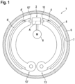
- FIG. 1 shows an example and greatly simplified a generic drum brake 1 in simplex design.
- Two essentially arc-shaped brake shoes 4, 4' each rotatably supported at their first end 13, 13', are each spread apart at their second end 12, 12' by a spreading unit 2 and pressed against the radial inner wall 7 of a cup-shaped brake drum 6.
- the brake drum 6 is connected to a vehicle wheel, not shown, and rotates together with this relative to the brake shoes 4, 4'.
- the brake pads 5, 5' attached to the brake shoes 4, 4' rub against the inner wall 7.
- the spreader unit 2 in the drum brake is preferably arranged in a floating manner along its central axis A.
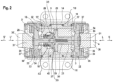
- each brake shoe mount 31, 31' has a transverse slot 36, 36', in which a flat end 12, 12' of a brake shoe 4, 4' is arranged.
- the spreader unit 2 also has an essentially tubular housing 14 equipped with a mounting flange.
- the drive of the spreading unit 2 is carried out by a in the 1 indicated electromotive drive unit 8 on the external toothing 10 of a drive sleeve 9, which is thereby rotated about the axis A and is supported in the housing 14 via roller bearings 15, 15' and is axially fixed by securing elements 16, 16'.
- the drum brake 1 according to the invention is provided as a service brake, all braking processes and not merely a static, constant force effect when parking are initiated via the drive sleeve 9 .
- roller bearings 15, 15' are designed as nail bearings, but other types of roller bearings are also permissible within the invention.
- the braking process takes place via the ball ramp devices 3, 3' onto the brake shoe mounts 31, 31' and the brake shoes 4, 4' engaged with them.
- Each ball-ramp device 3, 3' essentially comprises a respective expanding piston 22, 23, an actuating piston 17, 18 which can be rotated about the axis A relative to the expanding piston 22, 23, and a multiplicity of balls 34.
- the first actuating piston 17 and the first expanding piston 22 or the second actuating piston 18 and the second expanding piston 23 each have the same circumferential circle on their end faces which are directed towards one another an equal number of indentations 32, 33, which are regularly distributed in the circumferential direction.
- the depressions 32 in the actuating pistons 17, 18 are each in a first circumferential direction—gradually flattening—formed, the depressions 33 in the expanding pistons 22, 23 correspond to the depressions 32, but are flattened in a second, opposite circumferential direction.
- a ball 34 is arranged between each depression 32 and 33 .
- the balls By turning the actuating piston 17, 18 relative to the expanding piston 22, 23 in an actuating direction, the balls roll 34 into the flattened areas of the depressions 32, 33 and push the piston pairings apart (and vice versa).
- the two expanding pistons 22, 23 are secured against rotation with respect to the housing 14 and can therefore only be displaced linearly along the axis A.
- the anti-twist device is ensured by supporting the respective brake shoe mount 31, 31' via the transverse slot 36, 36' on the brake shoe 4, 4'.
- Each brake shoe mount 31, 31' is connected to the associated expansion piston 22, 23 in a manner secured against rotation via an outer sleeve 35, 35' which is bent inwards at the edge.
- Each expanding piston 22, 23 is arranged axially spaced apart from the associated brake shoe mount 31, 31' within the outer sleeve 35, 35', with a spring element 37, 37' prestressed in between. This allows a limited linear movement in the axial direction and ensures that when the drum shrinks, the increase in clamping force is limited by the compression of the spring element 37 in order to prevent damage to the brake.
- the rotary motion required for the ball ramp devices 3, 3' is transmitted via a first actuating piston 17 and a second actuating piston 18.
- the two actuating pistons 17, 18 are arranged in the drive sleeve 9, for the purpose of uniform application of the brake linings 5, 5' to the inner wall 7, in an axially floating manner and secured against rotation by means of axial guidance.
- An adjustment device 26 essentially comprises an adjustment piston 19, which is in the flow of force with the first actuating piston 17, and a locking sleeve 27, which engages with the adjustment piston 19 and is secured against rotation relative to the second expanding piston 28, but can be displaced axially to a limited extent and is elastically prestressed against the adjustment piston.
- a separate adjusting piston 19 is screwed into the first actuating piston 17 with a threaded section 21 up to the stop in a threaded bore 20 and is thus located in the power flow between the first actuating piston 17 and the second actuating piston 18.
- the adjusting piston 19 has on its end face facing the second actuating piston 18 an axially protruding annular first sawtooth ramp 38 with a plurality of tooth-shaped ramps or notches inclined in a circumferential direction.
- the latching sleeve 27 is essentially integrated into the second actuating piston 18 . It has an axially protruding annular second sawtooth ramp 39 corresponding to the first sawtooth ramp 38, which also forms a plurality of tooth-shaped ramps or notches inclined in an opposite circumferential direction.
- the locking sleeve 27 is mounted via a central bore on a shaft 28 of the second expanding piston 23 so that it can be moved axially and is secured against rotation in relation to the housing 14 .
- a transverse pin 29 is provided in the shown embodiment in the shaft 28, on which the locking sleeve 27 is supported via an axially protruding slotted collar 42 in both circumferential directions.
- the detent sleeve 27 is permanently pressed onto the sawtooth ramp 38 of the adjustment piston 19 with a slight force by a compression spring 30 supported on the second actuating piston 18 .
- a sliding disk 43 reduces the friction and the torsion of the compression spring 30 when the second actuating piston 18 rotates.
- the compression spring 30 is designed as a wave spring.
- Other embodiments, such as a spiral spring or a plate spring assembly, are also permissible within the invention.
- the adjusting piston 19 rotates relative to the locking sleeve 27, which is immovable in the circumferential direction.
- the ramps of the adjusting piston 19 run onto the ramps of the locking sleeve 27 with each actuation or braking and press this slightly against the spring action of the compression spring 30 into the second actuating piston 18.
- the required stroke increases and thus the angle of rotation of the drive sleeve 9 and the adjustment piston 19 coupled to it.
- the 3a, b show a section of the area of the claw clutch, consisting of the locking sleeve 27 and the adjusting piston 19. Between these there is a locking chamber 50.
- a locking chamber 50 For this purpose there is an annular depression 51 in the end face of the adjusting piston 19 and a circular depression 52 coaxial thereto in the locking sleeve 27.
- the outer diameter of the annular depression 51 is larger than that of the circular depression 52.
- the saw teeth close radially on the outside towards the depressions ramps 38, 39 on.
- the bottoms of the recesses 51, 52 are parallel to and face each other.
- the locking space 50 is delimited on the one hand by the bottom of the annular recess 51 and on the other hand by the opposite sawtooth ramp 39 on the locking sleeve 27.
- a spiral spring 53 made of a bimetal is located within the annular recess 51.
- the depth of the annular recess corresponds to the width of the spiral spring 53.
- One side of the spiral spring 53 lies on the bottom of the annular recess 51, so that its other side reaches the tips of the sawtooth ramp 39 on the locking sleeve 27.
- the spiral spring 53 can be attached to a central pin in the annular recess 51 .
- the Figure 3a shows an unactuated brake when cold.
- the two sawtooth ramps 38, 39 engage in one another, so that the spiral spring 53 protrudes into the circular depression 52. This is possible because its cold diameter is smaller than the diameter of the circular recess 52.
- the diameter of the spiral spring 53 remains smaller than the diameter of the circular recess 52, so that - like the Figure 3b shows, the annular recess 51 does not fill up to its outer diameter, although the two sawtooth ramps 38, 39 are disengaged and fall back into the next latching stage with a further rotation, so that the clearance can be corrected for wear as a result, as is the case in connection with Fig.2 is described.
- dasein center 55 possesses from the z. B.
- four bimetal having arms 56 go out. When cold, the arms 56 are shortened ( Figure 4a ), when heated they are stretched ( Figure 4b ), so that their distal ends lie in the locking space 50 between the locking sleeve 27 and the adjusting piston so that the sawtooth ramps 38, 39 cannot assume a twisted locking position.
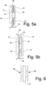
- FIG. 1 shows an embodiment of the bimetal element in the form of two coaxially arranged disc springs 60, 61 consisting of a bimetal, which are arranged coaxially in such a way that their mutually facing surfaces are concave in the cold state. Their edges in the barrier space 50 are thus close together and cannot fill the width of the barrier space 50 .
- the disc springs fold over so that their concave sides are now on the outside and their edges are spaced. As a result, they fill the width of the locking space 50 so that the sawtooth ramps 38, 39 cannot assume a twisted latching position, which prevents readjustment.
Landscapes
- Engineering & Computer Science (AREA)
- General Engineering & Computer Science (AREA)
- Mechanical Engineering (AREA)
- Transportation (AREA)
- Braking Arrangements (AREA)
Description
- Die Erfindung bezieht sich auf eine, insbesondere elektromechanisch antreibbare, Spreizeinheit für eine Trommelbremse eines Kraftfahrzeugs, umfassend ein Gehäuse und zwei in Bezug auf das Gehäuse verdrehgesichert angeordnete erste und zweite Bremsschuhaufnahmen, welche linear entlang einer Achse voneinander weg jeweils in eine Spreizrichtung sowie zueinander jeweils in eine Löserichtung betätigbar sind und auf jeweils einen ersten und einen zweiten, mit jeweils einem Bremsbelag versehenen Bremsschuh einwirken, wobei die Linearbewegung der Bremsschuhaufnahmen durch eine oder mehrere Rot-Trans-Wandler-Vorrichtungen erzeugt wird, und wobei eine Nachstelleinrichtung zum Ausgleich eines durch einen Verschleiß der Bremsbeläge sich erhöhenden Betätigungsweg zwischen den Betätigungskolben angeordnet ist, die so eingerichtet ist, dass sie den Abstand der Betätigungskolben in wenigstens einen Nachstellschritt ändert, wenn der Betätigungsweg einen Sollwert überschritten hat.
- Eine Spreizeinheit ist in der Offenlegungsschrift
DE 10 2017 218 219 A1 beschrieben. Die Nachstelleinrichtung hat die Aufgabe, den Verschleiß der Bremsbeläge auszugleichen, so dass der Abstand zwischen dem Belag und der Bremstrommel, das Lüftspiel, unabhängig von dem Verschleißzustand des Belages im Wesentlichen gleich bleibt, so dass die Spreizeinheit zur Betätigung der Bremse stets den gleichen Betätigungsweg auszuführen hat. - Bei einer lang andauernden Bremsung, z. B. auf einer Gefällstrecke, kommt es zu einer starken Erwärmung der Bremse, wobei sich die Bremstrommel weitet, so dass zwecks automatischem Wegausgleich bzw. zwecks Aufrechterhaltung der Bremswirkung die Spreizeinheit einen höheren Betätigungsweg ausführen muss, als im kalten (geschrupften) Trommelzustand. Dieser Ausgleichwird zu einer Nachstellung führen, obwohl kein entsprechender Verschleiß vorliegt. Nach Abkühlung der Bremse ist das Lüftspiel daher entsprechend verkleinert bzw. ist es nicht ausgeschlossen, dass der Belag an der Bremstrommel haften bleibt, bzw. dass sich die Trommelbremse unerwünscht verkeilt, d.h. unlösbar wird. Um dies zu vermeiden, wird das originäre Lüftspiel entsprechend vergrößert gewählt, was aber höhere Betätigungswege bedeutet. Um trotz allem eine schnell wirkende Bremse zu erhalten, muss der Motor, der die Spreizeinheit antreibt, schnell genug ansprechen und die Spreizeinheit darf keine zu große innere Reibung aufweisen. Dies erhöht den Bauaufwand und den Energiebedarf für eine Bremsung.
- Die Erfindung beruht daher auf der Aufgabe, eine Spreizeinheit zu schaffen, die trotz eines verhältnismäßig klein dimensionierten, originären Lüftspiels gewährleistet, dass es nicht zu einer Anhaftung/Verkeilung zwischen Reibbeläge und Bremstrommel kommt, wenn die Bremstrommel zu Beginn der Bremsung temperaturbedingt ausgedehnt/ausgeweitet war. Die Erfindung ist definiert in dem unabhängigen Anspruch 1.
- Zur Lösung der Aufgabe sieht die Erfindung vor, dass eine thermisch aktivierbare Sperreinrichtung vorgesehen ist, die so eingerichtet ist, dass bei einer Temperatur oberhalb von einem Sollwert die Ausführung eines Nachstellschrittes durch die Nachstelleinrichtung mechanisch verhindert ist.
- Auf diese Weise wird automatisch stromlos erreicht, dass bei einer erfassten Bremsentemperatur, die oberhalb von einem vorgegeben, definierten Temperatursollwert liegt, zwecks Kompensation gar kein Nachstellschritt oder ein reduzierter Nachstellschritt ausgeführt wird, so dass eine übermäßige Nachstellung verhindert ist. Denn anderenfalls würde der nachgestellte Betätigungsweg der Spreizeinheit wegen der temperurbedingten Weitung der Bremse dasjenige Maß annehmen, das bei einer kalten Bremse mit einem hohen Verschleiß der Bremsbeläge verknüpft ist. Da der Nachstellschritt verhindert oder angepasst ist, stellt sich nach einer Bremsung, die mit einer erhöhten Temperatur der Bremse einhergeht, und nach der Abkühlung der Bremse das originäre ausgelegte (unbeeinflusste) Lüftspiel wieder ein. Eine verschleißbedingte Nachstellung erfolgt also nur dann, wenn die Temperatur der Bremse bei Bremsbetätigung/Bremsung nicht über den Temperatursollwert erhöht ist.
- Vorzugsweise weist die Nachstelleinrichtung eine aus zwei Klauen bestehende schrittweise arbeitende Freilaufkupplung auf, wobei die Klauen im Freilauf einen relativen Hub ausführen und wobei die eine Klaue drehgesichert mit der ersten Bremsschuhaufnahme und die andere Klaue über eine Gewindespindel mit dem zweiten Betätigungskolben verbunden ist.
- Bei einer Betätigung der Bremse dreht sich die erste Bremsschuhaufnahme gegenüber dem zweiten Betätigungskolben in Freilaufrichtung der Klauenkupplung. Solange der Drehwinkel unterhalb einer vorgegebenen Schrittweite bleibt, dreht sich die Freilaufkupplung beim Lösen der Bremse wieder in ihre Ursprungsposition zurück. Wird die Schrittweite bei einer Bremsung aber überschritten, verbleibt die Freilaufkupplung beim Lösen der Bremse in der erreichten Winkelposition, wodurch der zweite Betätigungskolben mittels der Gewindespindel axial gegenüber dem ersten Betätigungskolben dauerhaft versetzt wird, wobei der Versatz den bis dahin erreichten Verschleiß des Bremsbelages ausgleicht.
- Bei Freilauf entfernen sich die Klauen voneinander, führen also einen relativen Hub aus. Dies kann genutzt werden, um auch beim Überschreiten der Schrittweite es der Freilaufkupplung zu ermöglichen, in ihre Ausgangsposition zu gelangen. Dazu ist die Sperreinrichtung wirkmäßig parallel zur Klauenkupplung angeordnet und hält im aktivierten Zustand die Klauen getrennt.
- Vorzugsweise besitzen die Klauen auf jeweils einer ihrer Stirnseiten auf einem Kreis verlaufende und ineinandergreifende Sägezahnrampen, wobei die Länge einer Rampe auf dem Kreisbogen die vorgegebene Schrittweite und die Höhe der Rampe einen maximalen Klauenhub definiert. Jede Rampe bildet eine Raste, so dass die Klauenkupplung in die nächste Raste springt, wenn die Schrittweite erreicht ist.
- Die Sägezahnrampen bewirken, dass die gegenseitige Verdrehung der Klauen in eine Umfangsrichtung gesperrt und in der entgegengesetzten Umfangsrichtung eine axial gerichtete Kraft ausgeübt wird. Wenn im letzteren Fall die beiden Klauen gegeneinander gedreht werden, gleiten die die Rampen aufeinander, so dass die Klauen voneinander wegbewegt werden. Sobald der Betätigungsweg der Spreizeinheit verschleißbedingt zu groß wird, wird die Drehung der Klauen größer als die Schrittweite, so dass die Klauen in die nächste Raste springen. Beim Lösen der Bremse wird die mit der ersten Bremsschuhaufnahme verbundene Klaue die andere Klaue mitnehmen, so dass deren Drehung durch die Spindelverbindung in eine translatorische Bewegung des zweiten Betätigungskolbens umgesetzt wird. Dadurch erhalten die beiden Betätigungskolben einen größeren Abstand voneinander, so dass das ursprüngliche Lüftspiel wiederhergestellt wird.
- Bei einer starken Erwärmung der Bremse während des Bremsvorganges wird sich der Betätigungsweg ebenfalls vergrößern, was aber nicht zu einer Nachstellung führen soll. Daher verhindert die Sperreinrichtung ein Eingreifen der Klaue in die nächste Raste, wodurch diese beim Lösen der Bremse in die ursprüngliche Raste zurückfällt. Es erfolgt somit keine Nachstellung. Diese ist auch nicht gewollt, da der erhöhte Betätigungsweg nicht durch einen Abrieb der Beläge, sondern durch eine temperaturbedingte Weitung der Bremstrommel bewirkt wurde.
- Vorzugsweise wird die Sperreinrichtung durch ein Bimetallelement dargestellt, wobei zwischen den Klauen ein Sperrraum liegt, der seitlich von den Klauen begrenzt ist, und wobei das Bimetallelement so angeordnet ist, dass es sich jedenfalls dann in den oder im Sperrraum auszudehnen vermag, wenn der maximale Klauenhub erreicht worden ist.
- Spätestens wenn sich die Klauen wegen eines erhöhten Betätigungsweges soweit gedreht und sich dabei voneinander entfernt haben, dass die Klauen in die nächste Raste springen würden, schiebt sich das Bimetallelement in den Sperrraum oder dehnt sich im Sperrraum aus und verhindert dies, weil die Klauen sich beidseitig an das Bimetallelement anlegen, statt in eine Raste zurückzufallen.
- Eine Ausführung des Bimetallelementes kann aus einer Spiralfeder bestehen, deren Durchmesser sich temperaturbedingt ändert und die so angeordnet ist, dass ihr äußerer Rand bei einer temperaturbedingten Ausdehnung in den Sperrraum gelangt. Diese Spiralfeder wird koaxial zur Achse der Spreizeinheit zwischen den beiden Klauen angeordnet. Bei einer Erwärmung der Bremse dehnt sich die Spiralfeder aus, so dass ihr äußerer Rand in den besagten Sperrraum gelangt.
- Eine andere Möglichkeit besteht darin, dass das Bimetallelement wenigstens einen von einem Zentrum ausgehenden Arm aufweist, der sich temperaturbedingt verlängert und der so angeordnet ist, dass sein distales Ende bei einer temperaturbedingten Verlängerung des Armes in den Sperrraum gelangt.
- Um auf den Umfang eine gleichmäßige Beabstandung der Klauen zu gewährleisten, können naturgemäß auch mehrere Arme sternförmig angeordnet sein.
- Eine weitere Ausführung des Bimetallelements umfasst zwei gegensinnig angeordneten Tellerfedern, deren jeweils eine Seitenfläche temperaturbedingt eine konvexe oder konkave Form annimmt und deren äußere Ränder sich in dem Sperrraum befinden.
- Im kalten Zustand sind die Tellerfedern so angeordnet, dass ihre zugewandten Flächen konkav ausgeführt sind, so dass ihre äußeren Ränder nah beieinander liegen und die Breite des Sperrraums bei einer unbetätigten Bremse nicht ausfüllen. Wird eine bestimmte Solltemperatur erreicht, klappen die Tellerfedern um, so dass die einander zugewandten Flächen konvex sind. Die äußeren Ränder sind dann in der Lage, sich an die beiden Klauen zu legen und diese wenigstens auf einem Abstand zu halten, der größer ist als der Klauenhub.
- Falle es notwendig ist, können mehrere Tellerfederpaare hintereinander angeordnet werden, die darüber hinaus mit Abstandsringen auf Abstand gehalten werden.
- Die Rot-Trans-Wandlerbaugruppe kann verschiedenartig kombiniert ausgebildet vorliegen. Zwecks elektromechanischer Betätigung kooperiert die erfindungsgemäße Spreizvorrichtung mit einem elektromotorischen Aktuator, der insbesondere rationell als selbständig handhabbare bzw. anmontierbare Motor-Getriebebaueinheit ausgebildet sein darf. Eine erfindungsgemäß ausgebildete Spreizeinheit kann in einem elektrischen Trommelbremssystem zwecks Kooperation bzw. Interaktion d.h. Regelung oder Steuerung der Aktuatorik über eine elektronische Steuereinheit mit einer elektrischen Lastmesseinrichtung verfügen, und wobei die Lastmesseinrichtung ganz grundsätzlich an einem beliebigen Ort integriert vorliegen darf. Demzufolge ist es erfindunggemäß ermöglicht, ein radindividuell steuer- bzw. regelbares elektromechanisches Kraftfahrzeugtrommelbremssystem, umfassend mindesten zwei Trommelbremsen auf einer gemeinsamen Fahrzeugachse, vorzusehen, die als Betriebsbremsanlagenkomponente ausgebildet sind, und dementsprechend regelbar sowie insbesondere fremdansteuerbar vorliegen können. Eine flankierend zum Getriebe mittelbar oder unmittelbar angebaute oder integrierte, d.h. im weitesten Sinne die antriebsstrangnahe Platzierung der erfindungsgemäß ausgerüsteten Trommelbremse/Spreizeinrichtung ist möglich.
- Die Klauenkupplung wird vorzugsweise so ausgeführt, dass die mit der ersten Bremsschuhaufnahme verbundene Klaue als Rasthülse ausgebildet ist, die fest mit der ersten Bremsschuhaufnahme verbunden ist, und dass die mit dem zweiten Betätigungskolben gekoppelte Klaue als Nachstellkolben ausgebildet ist, wobei die Rasthülse gegenüber der zweiten Bremsschuhaufnahme verdrehgesichert, gegenüber dem zweiten Betätigungskolben axial begrenzt verschiebbar sowie gegen den Nachstellkolben elastisch vorgespannt angeordnet ist.
- Im Folgenden soll anhand von vier Ausführungsbeispielen die Erfindung näher erläutert werden. Dazu zeigen:
- Fig. 1
- eine stark vereinfachte Schnitteinsicht einer Trommelbremse in Simplex-Bauweise mit einer erfindungsgemäßen Spreizeinheit,
- Fig. 2
- eine Ausführungsform der Spreizeinheit im Axialschnitt noch ohne Sperreinrichtung,
- Fig. 3a, b, c
- eine vergrößerte Darstellung der Spreizeinheit mit einer ersten Ausführung der erfindungsgemäßen Sperreinrichtung mit einer Bimetall-Spiralfeder in verschiedenen Stadien einer Bremsbetätigung,
- Fig. 4a, b
- ein sternförmiges Bimetallelement als zweite Ausführungsform der erfindungsgemäßen Sperreinrichtung,
- Fig. 5a, b
- ein aus zwei Tellerfedern bestehendes Bimetallelement als dritte Ausführungsform der erfindungsgemäßen Sperreinrichtung und
- Fig. 6
- ein aus zwei Tellerfederpaaren bestehendes Bimetallelement als vierte Ausführungsform der erfindungsgemäßen Sperreinrichtung.
- Weil die grundsätzliche Funktionsweise sowohl einer Trommelbremse als auch einer Rot-Trans-Wandler-Vorrichtung (beispielsweise Kugel-Rampen-Vorrichtung) hinreichend bekannt ist, wird nachfolgend lediglich auf die erfindungswesentlichen Funktionseigenschaften eingegangen.
-
Fig. 1 zeigt beispielhaft und stark vereinfacht eine gattungsgemäße Trommelbremse 1 in Simplex-Bauweise. Andere bekannte Bauweisen von Trommelbremsen sind jedoch innerhalb der Erfindung ebenso adaptierbar. Zwei, jeweils an ihrem ersten Ende 13, 13' drehbar angelehnte, im Wesentlichen kreisbogenförmige Bremsschuhe 4, 4' werden jeweils an ihrem zweiten Ende 12, 12' durch eine Spreizeinheit 2 auseinandergespreizt und dabei gegen die radiale Innenwand 7 einer topfförmigen Bremstrommel 6 gepresst. Die Bremstrommel 6 ist mit einem nicht gezeigten Fahrzeugrad verbunden und verdreht sich zusammen mit diesem gegenüber den Bremsschuhen 4, 4'. Die an den Bremsschuhen 4, 4' angebrachten Bremsbeläge 5, 5' reiben dabei an der Innenwand 7. Durch den Verschleiß der Bremsbeläge 5, 5' vergrößert sich der für eine Bremsung erforderliche Spreizweg kontinuierlich bis hin zu einer definierten Verschleißgrenze. Um eine eventuell unsymmetrische, ungleichmäßige Anlage der Beläge 5, 5' an der Bremstrommel 6 auszugleichen, ist die Spreizeinheit 2 in der Trommelbremse vorzugsweise entlang deren zentralen Achse A schwimmend gelagert angeordnet. -
Fig. 2 zeigt eine erfindungsgemäße Ausführungsform der Spreizeinheit 2 in einem unbetätigten Ausgangszustand im Axialschnitt. Die Spreizeinheit 2 weist zwei Kugel-Rampen-Vorrichtungen 3, 3' auf, welche über Bremsschuhaufnahmen 31, 31' auf die Bremsschuhe 4, 4' einwirken. Jede Bremsschuhaufnahme 31, 31' verfügt hierfür über einen Querschlitz 36, 36', in dem jeweils ein flaches Ende 12, 12' eines Bremsschuhs 4, 4' angeordnet wird. Die Spreizeinheit 2 weist ferner ein im Wesentlichen rohrförmiges, mit einem Montageflansch ausgestattetes Gehäuse 14 auf. Der Antrieb der Spreizeinheit 2 erfolgt durch eine in derFig. 1 angedeutete elektromotorische Antriebseinheit 8 auf die Außenverzahnung 10 einer Antriebshülse 9, welche hierdurch um die Achse A verdreht wird und sich im Gehäuse 14 über Rolllager 15, 15' abstützt und durch Sicherungselemente 16, 16' axial fixiert ist. Weil die erfindungsgemäße Trommelbremse 1 als Betriebsbremse vorgesehen ist, werden sämtliche Bremsvorgänge und nicht etwa lediglich eine statische konstante Krafteinwirkung beim Parken über die Antriebshülse 9 initiiert. - In der gezeigten Ausführungsform sind die Rolllager 15, 15' als Nagellager ausgelegt, andere Rolllagertypen sind innerhalb der Erfindung ebenso zulässig. Der Bremsvorgang erfolgt über die Kugel-Rampen-Vorrichtungen 3, 3' auf die Bremsschuhaufnahmen 31, 31' und den mit diesen im Eingriff stehenden Bremsschuhen 4, 4'.
- Jede Kugel-Rampen-Vorrichtung 3, 3' umfasst im Wesentlichen jeweils einen Spreizkolben 22, 23, jeweils einen, gegenüber dem Spreizkolben 22, 23 um die Achse A drehbaren Betätigungskolben 17, 18 und eine Vielzahl von Kugeln 34. An ihren jeweils zueinander gerichteten Stirnseiten weisen der erste Betätigungskolben 17 und der erste Spreizkolben 22 beziehungsweise der zweite Betätigungskolben 18 und der zweite Spreizkolben 23 jeweils am gleichen Umfangskreis eine gleiche Anzahl von Vertiefungen 32, 33 auf, die in Umfangsrichtung regelmäßig verteilt angeordnet sind. Die Vertiefungen 32 in den Betätigungskolben 17, 18 sind jeweils in eine erste Umfangsrichtung - allmählich abflachend - ausgebildet, die Vertiefungen 33 in den Spreizkolben 22, 23 korrespondieren mit den Vertiefungen 32, sind jedoch in eine zweite, gegengerichtete Umfangsrichtung abgeflacht. Zwischen jeder Vertiefung 32 und 33 ist jeweils eine Kugel 34 angeordnet. Durch die Verdrehung des Betätigungskolbens 17, 18 gegenüber dem Spreizkolben 22, 23 in eine Betätigungsrichtung rollen die Kugeln 34 in die abflachenden Bereiche der Vertiefungen 32, 33 und schieben die Kolbenpaarungen auseinander (und vice versa).
- Die beiden Spreizkolben 22, 23 sind in Bezug auf das Gehäuse 14 verdrehgesichert und somit nur linear entlang der Achse A versetzbar. In der gezeigten Ausführungsform wird die Verdrehsicherung durch die Abstützung der jeweiligen Bremsschuhaufnahme 31, 31' über den Querschlitz 36, 36' am Bremsschuh 4, 4' sichergestellt. Jede Bremsschuhaufnahme 31, 31' ist dabei über eine randseitig nach innen abgekantete Außenhülse 35, 35' mit dem jeweiligen zugeordneten Spreizkolben 22, 23 verdrehgesichert verbunden. Dabei ist jeder Spreizkolben 22, 23 gegenüber der zugeordneten Bremsschuhaufnahme 31, 31' innerhalb der Außenhülse 35, 35' axial beabstandet mit jeweils einem dazwischen vorgespannten Federelement 37, 37' angeordnet. Dadurch wird eine begrenzte lineare Bewegung in Axialrichtung ermöglicht und hierdurch sichergestellt, dass beim Trommelschrumpfen die Spannkrafterhöhung durch die Kompression des Federelementes 37 begrenzt wird, um eine Beschädigung der Bremse auszuschließen.
- Die Übertragung von der für die Kugel-Rampen-Vorrichtungen 3, 3' notwendigen Drehbewegung wird über einen ersten Betätigungskolben 17 und einen zweiten Betätigungskolben 18 ausgeführt. Die beiden Betätigungskolben 17, 18 sind in der Antriebshülse 9, zwecks gleichmäßigen Anlegens der Bremsbeläge 5, 5' an die Innenwand 7, axial schwimmend sowie mittels Axialführung verdrehgesichert angeordnet.
- Eine Nachstelleinrichtung 26 umfasst im Wesentlichen einen Nachstellkolben 19, der im Kraftfluss mit dem ersten Betätigungskolben 17 steht, und eine mit dem Nachstellkolben 19 im Eingriff stehende Rasthülse 27, die gegenüber dem zweiten Spreizkolben 28 verdrehgesichert, jedoch axial begrenzt verschiebbar sowie gegen den Nachstellkolben elastisch vorgespannt angeordnet ist.
- Ein gesonderter Nachstellkolben 19 ist in den ersten Betätigungskolben 17 mit einem Gewindeabschnitt 21 bis auf Anschlag in eine Gewindebohrung 20 hineingedreht und liegt somit im Kraftfluss zwischen dem ersten Betätigungskolben 17 und dem zweiten Betätigungskolben 18. Der Nachstellkolben 19 weist an seiner dem zweiten Betätigungskolben 18 zugewandten Stirnseite eine axial vorgestreckte ringförmige erste Sägezahnrampe 38 mit mehreren, in eine Umfangsrichtung geneigten zahnförmigen Rampen beziehungsweise Rasten auf.
- Die Rasthülse 27 ist im Wesentlichen in dem zweiten Betätigungskolben 18 integriert angeordnet. Sie weist einen zu der ersten Sägezahnrampe 38 korrespondierende, axial vorgestreckte ringförmige zweite Sägezahnrampe 39 auf, welche ebenso mehrere, in eine entgegengesetzte Umfangsrichtung geneigte zahnförmige Rampen beziehungsweise Rasten ausbildet.
- Die Rasthülse 27 ist über eine Zentralbohrung auf einem Schaft 28 des zweiten Spreizkolbens 23 axial verschiebbar sowie in Bezug auf das Gehäuse 14 verdrehgesichert gelagert. Zur Verdrehsicherung ist bei der gezeigten Ausführungsform in dem Schaft 28 ein Querstift 29 vorgesehen, an dem sich die Rasthülse 27 über einen axial vorgestreckten geschlitzten Kragen 42 in beide Umfangsrichtungen abstützt.
- Die Rasthülse 27 wird durch eine an dem zweiten Betätigungskolben 18 abgestützte Druckfeder 30 permanent mit leichter Kraft auf die Sägezahnrampe 38 des Nachstellkolbens 19 gedrückt. Eine Gleitscheibe 43 verringert die Reibung und die Verdrehung der Druckfeder 30 bei Drehung des zweiten Betätigungskolbens 18.
- Die Druckfeder 30 ist in der gezeigten Ausführungsform als eine Wellenfeder ausgebildet. Weitere Ausführungsformen, wie beispielsweise eine Spiralfeder oder ein Tellerfederpaket, sind innerhalb der Erfindung ebenso zulässig.
- Beim Antreiben der beiden Betätigungskolben 17 und 18 durch die Antriebshülse 9 erfolgt eine Verdrehung des Nachstellkolbens 19 relativ zur der in Umfangsrichtung unbeweglichen Rasthülse 27. Hierbei laufen die Rampen des Nachstellkolbens 19 bei jeder Betätigung beziehungsweise Bremsung auf die Rampen der Rasthülse 27 auf und drücken diese entgegen der Federwirkung der Druckfeder 30 geringfügig in den zweiten Betätigungskolben 18 hinein. Bei zunehmendem Verschleiß der Bremsbeläge 5, 5' vergrößert sich der erforderliche Hub und somit das Winkelmaß der Verdrehung der Antriebshülse 9 und des daran gekoppelten Nachstellkolbens 19. Sobald das Winkelmaß der Umfangslänge einer Rampe der Sägezahnrampen 38, 39 übersteigt, springt die Axialverzahnung zwischen der Rasthülse 27 und dem Nachstellkolben 19 in die nächste Raste. Wird danach die Bremse nach einer Bremsung gelöst, dreht sich der erste Betätigungskolben 17 zusammen mit der Antriebshülse 9 in die unbetätigte Ausgangsstellung zurück. Der Nachstellkolben 19 wird jedoch durch die verdrehgesicherte Rasthülse 27 am Rückdrehen gehindert und dadurch aus dem ersten Betätigungskolben 17 um das entsprechende Maß herausdreht. Somit erfolgt beim Lösen der Trommelbremse 1 eine schrittweise vollautomatisch weggesteuerte Nachstellung der Bremse.
- Im Folgenden werden Ausführungen der Sperreinrichtung beschrieben, die mit der Spreizeinheit gemäß
Fig. 2 zum Einsatz kommt. - Die
Fig. 3a, b zeigen dazu einen Ausschnitt aus dem Bereich der Klauenkupplung, bestehend aus der Rasthülse 27 und dem Nachstellkolben 19. Zwischen diesen befindet sich ein Sperrraum 50. Dazu befindet sich eine Ringvertiefung 51 in der Stirnseite des Nachstellkolbens 19 und eine dazu koaxiale Kreisvertiefung 52 in der Rasthülse 27. Dabei ist der Außendurchmesser der Ringvertiefung 51 größer als der der Kreisvertiefung 52. Radial außen zu den Vertiefungen schließen sich die Sägezahnrampen 38, 39 an. Die Böden der Vertiefungen 51, 52 sind parallel zueinander und liegen sich gegenüber. Der Sperrraum 50 wird einerseits begrenzt durch den Boden der Ringvertiefung 51 und andererseits durch die gegenüberliegende Sägezahnrampe 39 an der Rasthülse 27. - Eine Spiralfeder 53 aus einem Bimetall befindet sich innerhalb der Ringvertiefung 51. Die Tiefe der Ringvertiefung entspricht der Breite der Spiralfeder 53. Die eine Seite der Spiralfeder 53 liegt auf dem Boden der Ringvertiefung 51, so dass ihre andere Seite bis zu den Spitzen der Sägezahnrampe 39 an der Rasthülse 27 reicht. Dabei kann die Spiralfeder 53 an einem zentralen Zapfen in der Ringvertiefung 51 befestigt sein.
- Die
Fig.3a zeigt eine unbetätigte Bremse im kalten Zustand. Die beiden Sägezahnrampen 38, 39 greifen ineinander, so dass die Spiralfeder 53 in die Kreisvertiefung 52 ragt. Dies ist möglich, da ihr Durchmesser im kalten Zustand kleiner ist als der Durchmesser der Kreisvertiefung 52. Solange die Bremse bei einer Bremsung sich nicht übermäßig erwärmt, bleibt der Durchmesser der Spiralfeder 53 kleiner als der Durchmesser der Kreisvertiefung 52, so dass sie - wie dieFig. 3b zeigt, die Ringvertiefung 51 nicht bis zu deren Außendurchmesser ausfüllt, obwohl die beiden Sägezahnrampen 38, 39 außer Eingriff stehen und bei einer weiteren Drehung in die nächste Raststufe zurückfallen, damit in Folge eine verschleißbedingte Korrektur des Lüftspiels erfolgen kann, wie dies im Zusammenhang mitFig.2 beschrieben wird. - Anders ist die in Situation, wenn sich die Bremse stark erwärmt. Dies ist in der
Fig. 3c dargestellt. Wenn die beiden Sägezahnrampen 38, 39 außer Eingriff stehen, also den maximalen Klauenhub ausgeführt haben, dehnt sich die Ringfeder in den Sperrraum 50 zwischen der Sägezahnrampe 39 an der Rasthülse 27 und den Rand des Bodens der Ringvertiefung 51 aus. Damit können die Sägezahnrampen 38, 39, selbst wenn sie sich um eine Schrittweite gegeneinander verdreht haben, nicht in einer neuen Raststufe in Eingriff gelangen. Vielmehr werden die Sägezahnrampen 38, 39 beim Lösen der Bremse zunächst wieder ihre alte Winkellage einnehmen und dort später erneut in Eingriff gelangen, wenn sich die Spiralfeder 53 abgekühlt und wieder zusammengezogen hat. - Da aber nicht jede Bremsung mit einer erhöhten Wärmeentwicklung einhergeht, wird es bei einer der folgenden Bremsungen nicht zu einer Behinderung der Nachstellung kommen, so dass der bis dahin aufgelaufene Belagverschleiß ausgeglichen werden kann.
- Anstelle einer Spiralfeder kann auch ein sternförmiges Element gemäß den
Fig. 4a, b zum Einsatz kommen, dasein Zentrum 55besitzt von dem z. B. vier Bimetall aufweisende Arme 56 ausgehen. Im kalten Zustand sind die Arme 56 verkürzt (Fig. 4a ), im erwärmten Zustand werden sie gestreckt (Fig. 4b ), so dass sich ihre distalen Enden in den Sperrraum 50 so zwischen die Rasthülse 27 und den Nachstellkolben legen, dass die Sägezahnrampen 38, 39 keine verdrehte Rastposition einnehmen können. -
Fig. 5a zeigt eine Ausführung des Bimetallelementes in Form von zwei koaxial angeordneten, aus einem Bimetall bestehenden Tellerfedern 60, 61, die so koaxial angeordnet sind, dass ihre einander zugewandten Flächen im kalten Zustand konkav sind. Ihre Ränder in dem Sperrraum 50 liegen somit eng beieinander und können die Breite des Sperrraumes 50 nicht ausfüllen. Wenn sich die Bremse erwärmt (Fig. 5 b) , klappen die Tellerfedern um, so dass ihre konkaven Seiten jetzt außen liegen und ihre Ränder beabstandet sind. Dadurch füllen sie die Breite des Sperrraumes 50 aus, so dass die Sägezahnrampen 38,39 keine verdrehte Rastposition einnehmen können, wodurch eine Nachstellung verhindert wird. - Um auch bei kleinen Klappwinkeln der Tellerfedern 60, 61 eine ausreichend große Differenz zwischen der Randbreite im kalten und im erwärmten Zustand zu erreichen, können - wie dies in
Fig. 6 gezeigt ist - zwei (oder auch mehr) Tellerfedernpaare 65 hintereinander gesetzt werden, wobei sich zwischen ihnen jeweils ein Abstandsring 66 befindet. -
- 1
- Trommelbremse
- 2
- Spreizeinheit
- 3
- Rot-Trans-Wandler-Vorrichtung, insbesondere Kugel-Rampen-Vorrichtung
- 4
- Bremsschuh
- 5
- Bremsbelag
- 6
- Bremstrommel
- 7
- Innenwand
- 8
- Antriebseinheit
- 9
- Antriebshülse
- 10
- Außenverzahnung
- 12
- Ende
- 13
- Ende
- 14
- Gehäuse
- 15
- Rolllager (Nadellager)
- 16
- Sicherungselement
- 17
- Betätigungskolben
- 18
- Betätigungskolben
- 19
- Nachstellkolben
- 20
- Gewindebohrung
- 21
- Gewindeabschnitt
- 22
- Spreizkolben
- 23
- Spreizkolben
- 26
- Nachstelleinrichtung
- 27
- Rasthülse
- 28
- Schaft
- 29
- Querstift
- 30
- Druckfeder
- 31
- Bremsschuhaufnahme
- 32
- Vertiefung
- 33
- Vertiefung
- 34
- Kugel
- 35
- Außenhülse
- 36
- Querschlitz
- 37
- Federelement
- 38
- Sägezahnrampe
- 39
- Sägezahnrampe
- 42
- Kragen
- 43
- Gleitscheibe
- 50
- Sperrraum
- 51
- Ringvertiefung
- 52
- Kreisvertiefung
- 53
- Spiralfeder
- 55
- Zentrum
- 56
- Arme
- 60
- Tellerfeder
- 61
- Tellerfeder
- 65
- Tellerfedernpaare
- 66
- Abstandsring
- A
- Achse
Claims (14)
- Spreizeinheit (2) für eine Trommelbremse (1), umfassend ein Gehäuse (14) und zwei in Bezug auf das Gehäuse (14) verdrehgesichert angeordnete erste und zweite Bremsschuhaufnahmen (31, 31'), welche linear entlang einer Achse (A) voneinander weg jeweils in eine Spreizrichtung (S, S') sowie zueinander jeweils in eine Löserichtung (L, L') betätigbar sind und auf jeweils einen ersten und einen zweiten, mit jeweils einem Bremsbelag (5, 5') versehenen Bremsschuh (4, 4') einwirken, mit einer oder mehreren Rot-Trans-Wandler-Vorrichtungen, und wobei eine Nachstelleinrichtung (26) zum Ausgleich eines durch einen Verschleiß der Bremsbeläge (5, 5') sich erhöhenden Betätigungsweg zwischen den Betätigungskolben angeordnet ist, die so eingerichtet ist, dass sie den Abstand der Betätigungskolben in wenigstens einen Nachstellschritt ändert, wenn der Betätigungsweg einen Sollwert überschritten hat, dadurch gekennzeichnet, dass eine thermisch aktivierbare Sperreinrichtung vorgesehen ist, die so eingerichtet ist, dass bei einer Temperatur über einen Sollwert die Ausführung des Nachstellschrittes durch die Nachstelleinrichtung mechanisch verhindert ist.
- Spreizeinheit nach Anspruch 1, dadurch gekennzeichnet, dass die Nachstelleinrichtung (26) eine aus zwei Klauen bestehende Freilaufkupplung aufweist, wobei die Klauen im Freilauf einen relativen Hub ausführen und wobei die eine Klaue drehgesichert mit der ersten Bremsschuhaufnahme (31) und die andere Klaue über eine Gewindespindel mit dem zweiten Betätigungskolben (18) verbunden ist, und dass die Sperreinrichtung wirkmäßig parallel zur Klauenkupplung angeordnet ist und daher im aktivierten Zustand die Klauen getrennt hält.
- Spreizeinheit nach Anspruch 1, dadurch gekennzeichnet, dass die Klauen auf jeweils einer ihrer Stirnseiten auf einem Kreis verlaufende und ineinandergreifende Sägezahnrampen (38, 39) besitzen, wobei die Länge einer Rampe auf dem Kreisbogen die vorgegebene Schrittweite und die Höhe der Rampe einen maximalen Klauenhub definiert.
- Spreizeinheit nach Anspruch 2 oder 3, dadurch gekennzeichnet, dass die Sperreinrichtung ein Bimetallelement aufweist und dass zwischen den Klauen ein Sperrraum (50) liegt, der seitlich von den Klauen begrenzt ist, wobei das Bimetallelement so angeordnet ist, dass es sich jedenfalls dann in den Sperrraum hinein oder im Sperrraum auszudehnen vermag, wenn der maximale Klauenhub erreicht worden ist.
- Spreizeinheit nach Anspruch 4, dadurch gekennzeichnet, dass das Bimetallelement eine Spiralfeder (53) aufweist deren Durchmesser sich temperaturbedingt ändert und die so angeordnet ist, das ihr äußerer Rand bei einer temperaturbedingten Ausdehnung in den Sperrraum (50) gelangt.
- Spreizeinheit nach Anspruch 4, dadurch gekennzeichnet, dass das Bimetallelement wenigstens einen von einem Zentrum ausgehenden Arm aufweist der sich temperaturbedingt verlängert und der so angeordnet ist, dass sein distales Ende bei einer temperaturbedingten Verlängerung des Armes in den Sperrraum (50) gelangt.
- Spreizeinheit nach Anspruch 6, dadurch gekennzeichnet, dass das Bimetallelement mehrere Arme aufweist, die vorzugsweise sternförmig angeordnet sind.
- Spreizeinheit nach Anspruch 4, dadurch gekennzeichnet, dass das Bimetallelement zwei gegensinnig angeordnete Tellerfedern (60, 61) aufweist, deren jeweils eine Seitenfläche temperaturbedingt eine konvexe oder konkave Form annimmt und deren äußere Ränder sich in dem Sperrraum (50) befinden.
- Spreizeinheit nach Anspruch 8, dadurch gekennzeichnet, dass wenigstens zwei Tellerpaare vorgesehen sind.
- Spreizeinheit nach Anspruch 9, dadurch gekennzeichnet, dass sich zwischen den Tellerpaaren ein Abstandsring befindet.
- Spreizeinheit nach einem der vorhergehenden Ansprüche 2 bis 9, dadurch gekennzeichnet, dass die mit der ersten Bremsschuhaufnahme verbundene Klaue als Rasthülse (27) ausgebildet ist, die fest mit der ersten Bremsschuhaufnahme (31) verbunden ist und dass die mit dem zweiten Betätigungskolben gekoppelte Klaue als Nachstellkolben ausgebildet ist, wobei die Rasthülse (27) gegenüber der zweiten Bremsschuhaufnahme (31') verdrehgesichert, gegenüber dem zweiten Betätigungskolben (18) axial begrenzt verschiebbar sowie gegen den Nachstellkolben (19) elastisch vorgespannt angeordnet ist.
- Spreizeinheit nach einem oder mehreren der vorhergehenden Ansprüche 1-11, dadurch gekennzeichnet, dass zumindest eine Rot-Trans-Wandler-Vorrichtung zwecks Linearbewegung einer Bremsschuhaufnahme (31,31') ausgebildet ist, mittelsa) einer Kugel-Rampen-Vorrichtungen (3, 3'), wobei eine erste Kugel-Rampen-Vorrichtung (3) einen ersten um eine Achse (A) drehbar angeordneten Betätigungskolben (17) und optional mit einer zweiten Kugel-Rampen-Vorrichtung (3') die einen zweiten, um eine Achse (A) drehbar angeordneten Betätigungskolben (18) aufweist, und /oder aufweisendb) wenigstens eine oder mehrere Mutter-Spindel-Getriebe wie insbesondere ein Mutter-Spindel-Getriebe mit eingefügten Wälzkörpern, nämlich insbesondere mit Kugeln, und oderc) beliebige Mischkonstellation mit Merkmalen der Varianten a) und/ oder b).
- Spreizeinheit nach einem oder mehreren der vorhergehenden Ansprüche 1-12, dadurch gekennzeichnet, dass diese mit Hilfe eines elektromechanischen Aktuators umfassend einen Elektromotor elektromechanisch antreibbar ausgebildet ist.
- Spreizeinheit nach einem oder mehreren der vorhergehenden Ansprüche 1-13, dadurch gekennzeichnet, dass diese mittelbar oder unmittelbar mit einer elektrischen Lastmesseinrichtung ausgestattet ist, wie insbesondere mit der Lastmesseinrichtung zwecks elektrisch gesteuerter und/oder geregelter Zuspannung der Trommelbremse kooperiert.
Applications Claiming Priority (2)
| Application Number | Priority Date | Filing Date | Title |
|---|---|---|---|
| DE102019208223.8A DE102019208223A1 (de) | 2019-06-05 | 2019-06-05 | Elektromechanisch antreibbare Spreizeinheit für eine Trommelbremse |
| PCT/EP2020/064683 WO2020244991A1 (de) | 2019-06-05 | 2020-05-27 | Spreizeinheit für eine kraftfahrzeugtrommelbremse |
Publications (2)
| Publication Number | Publication Date |
|---|---|
| EP3980657A1 EP3980657A1 (de) | 2022-04-13 |
| EP3980657B1 true EP3980657B1 (de) | 2023-07-26 |
Family
ID=71016495
Family Applications (1)
| Application Number | Title | Priority Date | Filing Date |
|---|---|---|---|
| EP20730998.0A Active EP3980657B1 (de) | 2019-06-05 | 2020-05-27 | Spreizeinheit für eine kraftfahrzeugtrommelbremse |
Country Status (5)
| Country | Link |
|---|---|
| US (1) | US12234875B2 (de) |
| EP (1) | EP3980657B1 (de) |
| CN (1) | CN113853489A (de) |
| DE (1) | DE102019208223A1 (de) |
| WO (1) | WO2020244991A1 (de) |
Family Cites Families (16)
| Publication number | Priority date | Publication date | Assignee | Title |
|---|---|---|---|---|
| GB2151319B (en) * | 1980-12-06 | 1986-01-02 | Lucas Ind Plc | Automatic adjuster for a shoe drum brake |
| FR2611011B1 (fr) * | 1987-02-12 | 1994-05-13 | Bendix France | Frein a tambour a reglage automatique verrouille a haute temperature |
| US4938320A (en) * | 1989-01-10 | 1990-07-03 | General Motors Corporation | Apparatus and method of utilization thereof of a thermal compensating self-adjusting vehicle wheel drum brake |
| US5150773A (en) * | 1991-03-21 | 1992-09-29 | General Motors Corporation | Electrically actuated electric brake with wear compensating adjuster |
| DE9208465U1 (de) | 1992-06-25 | 1993-10-28 | Lucas Industries P.L.C., Solihull, West Midlands | Selbsttätige Nachstellvorrichtung für eine Bremse, insbesondere eine Trommelbremse |
| JPH08105471A (ja) * | 1994-10-07 | 1996-04-23 | Hosei Brake Kogyo Kk | シュー間隙自動調節機構付ドラムブレーキ |
| US6345702B1 (en) * | 1998-02-19 | 2002-02-12 | Automotive Products (Italia) Spa | Brake adjusters |
| DE19858745A1 (de) * | 1998-12-18 | 2000-06-21 | Continental Teves Ag & Co Ohg | Trommelbremse mit thermischer Nachstellungsbegrenzung |
| DE102009036222B4 (de) * | 2009-08-05 | 2013-02-21 | Knott Gmbh | Innenbackenbremse mit thermisch geregelter Nachstelleinrichtung für das Bremsbackenlüftspiel |
| CN201982549U (zh) * | 2011-03-16 | 2011-09-21 | 湖南运达机械制造有限公司 | 具有温度补偿功能的液压制动后分泵 |
| DE202013103918U1 (de) * | 2012-12-10 | 2014-03-12 | Al-Ko Kober Se | Radbremse |
| DE102013224922A1 (de) * | 2013-12-04 | 2015-06-11 | Continental Teves Ag & Co. Ohg | Elektromechanisch betätigbare Trommelbremse |
| DE102014226270A1 (de) * | 2014-12-17 | 2016-06-23 | Continental Teves Ag & Co. Ohg | Spreizeinrichtung für eine mit einer Nachstelleinrichtung versehenen Trommelbremse und Trommelbremse mit einer solchen Spreizeinrichtung |
| DE102014226268A1 (de) | 2014-12-17 | 2016-06-23 | Continental Teves Ag & Co. Ohg | Elektromechanisch betätigbare Spreizeinrichtung für eine mit einer Nachstelleinrichtung versehenen Trommelbremse |
| DE102017218219A1 (de) * | 2017-10-12 | 2019-04-18 | Continental Teves Ag & Co. Ohg | Spreizeinheit für Trommelbremse mit Verschleißwegnachstellung und die Trommelbremse |
| DE102018216488A1 (de) | 2018-09-26 | 2020-03-26 | Continental Teves Ag & Co. Ohg | Spreizeinrichtung mit einer Nachstellvorrichtung für eine Trommelbremse |
-
2019
- 2019-06-05 DE DE102019208223.8A patent/DE102019208223A1/de active Pending
-
2020
- 2020-05-27 CN CN202080035230.5A patent/CN113853489A/zh active Pending
- 2020-05-27 WO PCT/EP2020/064683 patent/WO2020244991A1/de not_active Ceased
- 2020-05-27 US US17/616,742 patent/US12234875B2/en active Active
- 2020-05-27 EP EP20730998.0A patent/EP3980657B1/de active Active
Also Published As
| Publication number | Publication date |
|---|---|
| EP3980657A1 (de) | 2022-04-13 |
| WO2020244991A1 (de) | 2020-12-10 |
| DE102019208223A1 (de) | 2020-12-10 |
| US20220333657A1 (en) | 2022-10-20 |
| US12234875B2 (en) | 2025-02-25 |
| CN113853489A (zh) | 2021-12-28 |
Similar Documents
| Publication | Publication Date | Title |
|---|---|---|
| DE4306505B4 (de) | Reibungskupplung | |
| EP1455106B1 (de) | Ausrücksysteme | |
| EP3695132B1 (de) | Spreizeinheit für trommelbremse mit verschleisswegnachstellung und die trommelbremse | |
| DE4345577B4 (de) | Reibungskupplung | |
| EP2377736B1 (de) | Kugelgewindetrieb für eine Kraftfahrzeugbremse und Kraftfahrzeugbremse | |
| EP3102845B1 (de) | Fahrzeugscheibenbremse | |
| EP1388682B1 (de) | Drehmomentübertragungsvorrichtung in einem Kraftfahrzeug | |
| DE9219029U1 (de) | Reibungskupplung | |
| DE102018002650A1 (de) | Betätigungsvorrichtung einer automatisierten Reibungskupplung | |
| EP2835547B1 (de) | Nachstelleinrichtung | |
| DE19547081A1 (de) | Betätigungsvorrichtung | |
| DE102014226270A1 (de) | Spreizeinrichtung für eine mit einer Nachstelleinrichtung versehenen Trommelbremse und Trommelbremse mit einer solchen Spreizeinrichtung | |
| EP3980657B1 (de) | Spreizeinheit für eine kraftfahrzeugtrommelbremse | |
| WO2017148777A1 (de) | Elektromechanischer aktuator zur betätigung eines durch reibungskraftschluss kraftübertragenden systems | |
| EP2878844B1 (de) | Scheibenbremse | |
| DE4244919C2 (de) | Reibungskupplung | |
| WO2018215632A1 (de) | Scheibenbremse und bremsbetätigungsmechanismus | |
| WO2018036589A1 (de) | Doppelschlingfeder, rotationseinrichtung und zu aktuierendes system | |
| DE102019207671B3 (de) | Spreizeinrichtung für eine Trommelbremse | |
| EP3857093B1 (de) | Spreizeinrichtung mit einer nachstellvorrichtung für eine trommelbremse | |
| EP3875796B1 (de) | Form- und reibschlüssige kupplung | |
| DE69805175T2 (de) | Verbesserungen an scheibenbremseinheiten | |
| DE102014226273A1 (de) | Elektromechanisch betätigbare Spreizeinrichtung für eine mit einer Nachstelleinrichtung versehenen Trommelbremse | |
| DE10016189A1 (de) | Doppelkupplung für ein Zahnräderwechselgetriebe eines Kraftfahrzeuges | |
| EP1683702B1 (de) | Klemmvorrichtung für eine Lenksäule |
Legal Events
| Date | Code | Title | Description |
|---|---|---|---|
| STAA | Information on the status of an ep patent application or granted ep patent |
Free format text: STATUS: UNKNOWN |
|
| STAA | Information on the status of an ep patent application or granted ep patent |
Free format text: STATUS: THE INTERNATIONAL PUBLICATION HAS BEEN MADE |
|
| PUAI | Public reference made under article 153(3) epc to a published international application that has entered the european phase |
Free format text: ORIGINAL CODE: 0009012 |
|
| STAA | Information on the status of an ep patent application or granted ep patent |
Free format text: STATUS: REQUEST FOR EXAMINATION WAS MADE |
|
| 17P | Request for examination filed |
Effective date: 20220105 |
|
| AK | Designated contracting states |
Kind code of ref document: A1 Designated state(s): AL AT BE BG CH CY CZ DE DK EE ES FI FR GB GR HR HU IE IS IT LI LT LU LV MC MK MT NL NO PL PT RO RS SE SI SK SM TR |
|
| RAP1 | Party data changed (applicant data changed or rights of an application transferred) |
Owner name: CONTINENTAL AUTOMOTIVE TECHNOLOGIES GMBH |
|
| DAV | Request for validation of the european patent (deleted) | ||
| DAX | Request for extension of the european patent (deleted) | ||
| GRAP | Despatch of communication of intention to grant a patent |
Free format text: ORIGINAL CODE: EPIDOSNIGR1 |
|
| STAA | Information on the status of an ep patent application or granted ep patent |
Free format text: STATUS: GRANT OF PATENT IS INTENDED |
|
| INTG | Intention to grant announced |
Effective date: 20230222 |
|
| GRAS | Grant fee paid |
Free format text: ORIGINAL CODE: EPIDOSNIGR3 |
|
| GRAA | (expected) grant |
Free format text: ORIGINAL CODE: 0009210 |
|
| STAA | Information on the status of an ep patent application or granted ep patent |
Free format text: STATUS: THE PATENT HAS BEEN GRANTED |
|
| P01 | Opt-out of the competence of the unified patent court (upc) registered |
Effective date: 20230522 |
|
| AK | Designated contracting states |
Kind code of ref document: B1 Designated state(s): AL AT BE BG CH CY CZ DE DK EE ES FI FR GB GR HR HU IE IS IT LI LT LU LV MC MK MT NL NO PL PT RO RS SE SI SK SM TR |
|
| REG | Reference to a national code |
Ref country code: CH Ref legal event code: EP |
|
| REG | Reference to a national code |
Ref country code: IE Ref legal event code: FG4D Free format text: LANGUAGE OF EP DOCUMENT: GERMAN |
|
| REG | Reference to a national code |
Ref country code: DE Ref legal event code: R096 Ref document number: 502020004397 Country of ref document: DE |
|
| REG | Reference to a national code |
Ref country code: LT Ref legal event code: MG9D |
|
| REG | Reference to a national code |
Ref country code: NL Ref legal event code: MP Effective date: 20230726 |
|
| PG25 | Lapsed in a contracting state [announced via postgrant information from national office to epo] |
Ref country code: NL Free format text: LAPSE BECAUSE OF FAILURE TO SUBMIT A TRANSLATION OF THE DESCRIPTION OR TO PAY THE FEE WITHIN THE PRESCRIBED TIME-LIMIT Effective date: 20230726 |
|
| PG25 | Lapsed in a contracting state [announced via postgrant information from national office to epo] |
Ref country code: GR Free format text: LAPSE BECAUSE OF FAILURE TO SUBMIT A TRANSLATION OF THE DESCRIPTION OR TO PAY THE FEE WITHIN THE PRESCRIBED TIME-LIMIT Effective date: 20231027 |
|
| PG25 | Lapsed in a contracting state [announced via postgrant information from national office to epo] |
Ref country code: IS Free format text: LAPSE BECAUSE OF FAILURE TO SUBMIT A TRANSLATION OF THE DESCRIPTION OR TO PAY THE FEE WITHIN THE PRESCRIBED TIME-LIMIT Effective date: 20231126 |
|
| PG25 | Lapsed in a contracting state [announced via postgrant information from national office to epo] |
Ref country code: SE Free format text: LAPSE BECAUSE OF FAILURE TO SUBMIT A TRANSLATION OF THE DESCRIPTION OR TO PAY THE FEE WITHIN THE PRESCRIBED TIME-LIMIT Effective date: 20230726 Ref country code: RS Free format text: LAPSE BECAUSE OF FAILURE TO SUBMIT A TRANSLATION OF THE DESCRIPTION OR TO PAY THE FEE WITHIN THE PRESCRIBED TIME-LIMIT Effective date: 20230726 Ref country code: PT Free format text: LAPSE BECAUSE OF FAILURE TO SUBMIT A TRANSLATION OF THE DESCRIPTION OR TO PAY THE FEE WITHIN THE PRESCRIBED TIME-LIMIT Effective date: 20231127 Ref country code: NO Free format text: LAPSE BECAUSE OF FAILURE TO SUBMIT A TRANSLATION OF THE DESCRIPTION OR TO PAY THE FEE WITHIN THE PRESCRIBED TIME-LIMIT Effective date: 20231026 Ref country code: LV Free format text: LAPSE BECAUSE OF FAILURE TO SUBMIT A TRANSLATION OF THE DESCRIPTION OR TO PAY THE FEE WITHIN THE PRESCRIBED TIME-LIMIT Effective date: 20230726 Ref country code: LT Free format text: LAPSE BECAUSE OF FAILURE TO SUBMIT A TRANSLATION OF THE DESCRIPTION OR TO PAY THE FEE WITHIN THE PRESCRIBED TIME-LIMIT Effective date: 20230726 Ref country code: IS Free format text: LAPSE BECAUSE OF FAILURE TO SUBMIT A TRANSLATION OF THE DESCRIPTION OR TO PAY THE FEE WITHIN THE PRESCRIBED TIME-LIMIT Effective date: 20231126 Ref country code: HR Free format text: LAPSE BECAUSE OF FAILURE TO SUBMIT A TRANSLATION OF THE DESCRIPTION OR TO PAY THE FEE WITHIN THE PRESCRIBED TIME-LIMIT Effective date: 20230726 Ref country code: GR Free format text: LAPSE BECAUSE OF FAILURE TO SUBMIT A TRANSLATION OF THE DESCRIPTION OR TO PAY THE FEE WITHIN THE PRESCRIBED TIME-LIMIT Effective date: 20231027 Ref country code: FI Free format text: LAPSE BECAUSE OF FAILURE TO SUBMIT A TRANSLATION OF THE DESCRIPTION OR TO PAY THE FEE WITHIN THE PRESCRIBED TIME-LIMIT Effective date: 20230726 |
|
| REG | Reference to a national code |
Ref country code: DE Ref legal event code: R081 Ref document number: 502020004397 Country of ref document: DE Owner name: CONTINENTAL AUTOMOTIVE TECHNOLOGIES GMBH, DE Free format text: FORMER OWNER: CONTINENTAL AUTOMOTIVE TECHNOLOGIES GMBH, 30165 HANNOVER, DE Ref country code: DE Ref legal event code: R081 Ref document number: 502020004397 Country of ref document: DE Owner name: AUMOVIO GERMANY GMBH, DE Free format text: FORMER OWNER: CONTINENTAL AUTOMOTIVE TECHNOLOGIES GMBH, 30165 HANNOVER, DE |
|
| PG25 | Lapsed in a contracting state [announced via postgrant information from national office to epo] |
Ref country code: PL Free format text: LAPSE BECAUSE OF FAILURE TO SUBMIT A TRANSLATION OF THE DESCRIPTION OR TO PAY THE FEE WITHIN THE PRESCRIBED TIME-LIMIT Effective date: 20230726 |
|
| P02 | Opt-out of the competence of the unified patent court (upc) changed |
Effective date: 20240207 |
|
| RAP4 | Party data changed (patent owner data changed or rights of a patent transferred) |
Owner name: CONTINENTAL AUTOMOTIVE TECHNOLOGIES GMBH |
|
| PG25 | Lapsed in a contracting state [announced via postgrant information from national office to epo] |
Ref country code: ES Free format text: LAPSE BECAUSE OF FAILURE TO SUBMIT A TRANSLATION OF THE DESCRIPTION OR TO PAY THE FEE WITHIN THE PRESCRIBED TIME-LIMIT Effective date: 20230726 |
|
| REG | Reference to a national code |
Ref country code: DE Ref legal event code: R097 Ref document number: 502020004397 Country of ref document: DE |
|
| PG25 | Lapsed in a contracting state [announced via postgrant information from national office to epo] |
Ref country code: SM Free format text: LAPSE BECAUSE OF FAILURE TO SUBMIT A TRANSLATION OF THE DESCRIPTION OR TO PAY THE FEE WITHIN THE PRESCRIBED TIME-LIMIT Effective date: 20230726 Ref country code: RO Free format text: LAPSE BECAUSE OF FAILURE TO SUBMIT A TRANSLATION OF THE DESCRIPTION OR TO PAY THE FEE WITHIN THE PRESCRIBED TIME-LIMIT Effective date: 20230726 Ref country code: ES Free format text: LAPSE BECAUSE OF FAILURE TO SUBMIT A TRANSLATION OF THE DESCRIPTION OR TO PAY THE FEE WITHIN THE PRESCRIBED TIME-LIMIT Effective date: 20230726 Ref country code: EE Free format text: LAPSE BECAUSE OF FAILURE TO SUBMIT A TRANSLATION OF THE DESCRIPTION OR TO PAY THE FEE WITHIN THE PRESCRIBED TIME-LIMIT Effective date: 20230726 Ref country code: DK Free format text: LAPSE BECAUSE OF FAILURE TO SUBMIT A TRANSLATION OF THE DESCRIPTION OR TO PAY THE FEE WITHIN THE PRESCRIBED TIME-LIMIT Effective date: 20230726 Ref country code: CZ Free format text: LAPSE BECAUSE OF FAILURE TO SUBMIT A TRANSLATION OF THE DESCRIPTION OR TO PAY THE FEE WITHIN THE PRESCRIBED TIME-LIMIT Effective date: 20230726 Ref country code: SK Free format text: LAPSE BECAUSE OF FAILURE TO SUBMIT A TRANSLATION OF THE DESCRIPTION OR TO PAY THE FEE WITHIN THE PRESCRIBED TIME-LIMIT Effective date: 20230726 |
|
| REG | Reference to a national code |
Ref country code: CH Ref legal event code: PK Free format text: DIE PUBLIKATION VOM 27.03.2024 WURDE AM 24.04.2024 IRRTUEMLICHERWEISE ERNEUT PUBLIZIERT. LA PUBLICATION DU 27.03.2024 A ETE REPUBLIEE PAR ERREUR LE 24.04.2024. LA PUBBLICAZIONE DEL 27.03.2024 E STATA ERRONEAMENTE RIPUBBLICATA IL 24.04.2024. |
|
| PG25 | Lapsed in a contracting state [announced via postgrant information from national office to epo] |
Ref country code: IT Free format text: LAPSE BECAUSE OF FAILURE TO SUBMIT A TRANSLATION OF THE DESCRIPTION OR TO PAY THE FEE WITHIN THE PRESCRIBED TIME-LIMIT Effective date: 20230726 |
|
| PLBE | No opposition filed within time limit |
Free format text: ORIGINAL CODE: 0009261 |
|
| STAA | Information on the status of an ep patent application or granted ep patent |
Free format text: STATUS: NO OPPOSITION FILED WITHIN TIME LIMIT |
|
| 26N | No opposition filed |
Effective date: 20240429 |
|
| PG25 | Lapsed in a contracting state [announced via postgrant information from national office to epo] |
Ref country code: SI Free format text: LAPSE BECAUSE OF FAILURE TO SUBMIT A TRANSLATION OF THE DESCRIPTION OR TO PAY THE FEE WITHIN THE PRESCRIBED TIME-LIMIT Effective date: 20230726 |
|
| PG25 | Lapsed in a contracting state [announced via postgrant information from national office to epo] |
Ref country code: BG Free format text: LAPSE BECAUSE OF FAILURE TO SUBMIT A TRANSLATION OF THE DESCRIPTION OR TO PAY THE FEE WITHIN THE PRESCRIBED TIME-LIMIT Effective date: 20230726 |
|
| PG25 | Lapsed in a contracting state [announced via postgrant information from national office to epo] |
Ref country code: BG Free format text: LAPSE BECAUSE OF FAILURE TO SUBMIT A TRANSLATION OF THE DESCRIPTION OR TO PAY THE FEE WITHIN THE PRESCRIBED TIME-LIMIT Effective date: 20230726 |
|
| REG | Reference to a national code |
Ref country code: CH Ref legal event code: PL |
|
| PG25 | Lapsed in a contracting state [announced via postgrant information from national office to epo] |
Ref country code: MC Free format text: LAPSE BECAUSE OF FAILURE TO SUBMIT A TRANSLATION OF THE DESCRIPTION OR TO PAY THE FEE WITHIN THE PRESCRIBED TIME-LIMIT Effective date: 20230726 |
|
| PG25 | Lapsed in a contracting state [announced via postgrant information from national office to epo] |
Ref country code: LU Free format text: LAPSE BECAUSE OF NON-PAYMENT OF DUE FEES Effective date: 20240527 |
|
| GBPC | Gb: european patent ceased through non-payment of renewal fee |
Effective date: 20240527 |
|
| PG25 | Lapsed in a contracting state [announced via postgrant information from national office to epo] |
Ref country code: MC Free format text: LAPSE BECAUSE OF FAILURE TO SUBMIT A TRANSLATION OF THE DESCRIPTION OR TO PAY THE FEE WITHIN THE PRESCRIBED TIME-LIMIT Effective date: 20230726 Ref country code: LU Free format text: LAPSE BECAUSE OF NON-PAYMENT OF DUE FEES Effective date: 20240527 Ref country code: CH Free format text: LAPSE BECAUSE OF NON-PAYMENT OF DUE FEES Effective date: 20240531 |
|
| REG | Reference to a national code |
Ref country code: BE Ref legal event code: MM Effective date: 20240531 |
|
| PG25 | Lapsed in a contracting state [announced via postgrant information from national office to epo] |
Ref country code: IE Free format text: LAPSE BECAUSE OF NON-PAYMENT OF DUE FEES Effective date: 20240527 |
|
| PG25 | Lapsed in a contracting state [announced via postgrant information from national office to epo] |
Ref country code: BE Free format text: LAPSE BECAUSE OF NON-PAYMENT OF DUE FEES Effective date: 20240531 |
|
| PG25 | Lapsed in a contracting state [announced via postgrant information from national office to epo] |
Ref country code: FR Free format text: LAPSE BECAUSE OF NON-PAYMENT OF DUE FEES Effective date: 20240531 |
|
| PG25 | Lapsed in a contracting state [announced via postgrant information from national office to epo] |
Ref country code: GB Free format text: LAPSE BECAUSE OF NON-PAYMENT OF DUE FEES Effective date: 20240527 |
|
| PGFP | Annual fee paid to national office [announced via postgrant information from national office to epo] |
Ref country code: DE Payment date: 20250531 Year of fee payment: 6 |
|
| PGFP | Annual fee paid to national office [announced via postgrant information from national office to epo] |
Ref country code: AT Payment date: 20250721 Year of fee payment: 5 |
|
| PG25 | Lapsed in a contracting state [announced via postgrant information from national office to epo] |
Ref country code: HU Free format text: LAPSE BECAUSE OF FAILURE TO SUBMIT A TRANSLATION OF THE DESCRIPTION OR TO PAY THE FEE WITHIN THE PRESCRIBED TIME-LIMIT; INVALID AB INITIO Effective date: 20200527 |
|
| PG25 | Lapsed in a contracting state [announced via postgrant information from national office to epo] |
Ref country code: CY Free format text: LAPSE BECAUSE OF FAILURE TO SUBMIT A TRANSLATION OF THE DESCRIPTION OR TO PAY THE FEE WITHIN THE PRESCRIBED TIME-LIMIT; INVALID AB INITIO Effective date: 20200527 |
|
| REG | Reference to a national code |
Ref country code: DE Ref legal event code: R081 Ref document number: 502020004397 Country of ref document: DE Owner name: AUMOVIO GERMANY GMBH, DE Free format text: FORMER OWNER: CONTINENTAL AUTOMOTIVE TECHNOLOGIES GMBH, 30175 HANNOVER, DE |