US4938320A - Apparatus and method of utilization thereof of a thermal compensating self-adjusting vehicle wheel drum brake - Google Patents
Apparatus and method of utilization thereof of a thermal compensating self-adjusting vehicle wheel drum brake Download PDFInfo
- Publication number
- US4938320A US4938320A US07/295,273 US29527389A US4938320A US 4938320 A US4938320 A US 4938320A US 29527389 A US29527389 A US 29527389A US 4938320 A US4938320 A US 4938320A
- Authority
- US
- United States
- Prior art keywords
- shoes
- brake
- adjuster
- pawl
- aperture
- Prior art date
- Legal status (The legal status is an assumption and is not a legal conclusion. Google has not performed a legal analysis and makes no representation as to the accuracy of the status listed.)
- Expired - Lifetime
Links
Images


Classifications
-
- F—MECHANICAL ENGINEERING; LIGHTING; HEATING; WEAPONS; BLASTING
- F16—ENGINEERING ELEMENTS AND UNITS; GENERAL MEASURES FOR PRODUCING AND MAINTAINING EFFECTIVE FUNCTIONING OF MACHINES OR INSTALLATIONS; THERMAL INSULATION IN GENERAL
- F16D—COUPLINGS FOR TRANSMITTING ROTATION; CLUTCHES; BRAKES
- F16D65/00—Parts or details
- F16D65/38—Slack adjusters
- F16D65/40—Slack adjusters mechanical
- F16D65/52—Slack adjusters mechanical self-acting in one direction for adjusting excessive play
- F16D65/56—Slack adjusters mechanical self-acting in one direction for adjusting excessive play with screw-thread and nut
- F16D65/561—Slack adjusters mechanical self-acting in one direction for adjusting excessive play with screw-thread and nut for mounting within the confines of a drum brake
- F16D65/563—Slack adjusters mechanical self-acting in one direction for adjusting excessive play with screw-thread and nut for mounting within the confines of a drum brake arranged adjacent to service brake actuator, e.g. on parking brake lever, and not subjected to service brake force
-
- F—MECHANICAL ENGINEERING; LIGHTING; HEATING; WEAPONS; BLASTING
- F16—ENGINEERING ELEMENTS AND UNITS; GENERAL MEASURES FOR PRODUCING AND MAINTAINING EFFECTIVE FUNCTIONING OF MACHINES OR INSTALLATIONS; THERMAL INSULATION IN GENERAL
- F16D—COUPLINGS FOR TRANSMITTING ROTATION; CLUTCHES; BRAKES
- F16D65/00—Parts or details
- F16D65/38—Slack adjusters
- F16D65/40—Slack adjusters mechanical
- F16D65/52—Slack adjusters mechanical self-acting in one direction for adjusting excessive play
- F16D65/56—Slack adjusters mechanical self-acting in one direction for adjusting excessive play with screw-thread and nut
- F16D65/561—Slack adjusters mechanical self-acting in one direction for adjusting excessive play with screw-thread and nut for mounting within the confines of a drum brake
- F16D65/566—Slack adjusters mechanical self-acting in one direction for adjusting excessive play with screw-thread and nut for mounting within the confines of a drum brake having a temperature-sensitive element preventing adjustment when brake is hot
Definitions
- the field of the present invention is that of apparatus and methods of utilization thereof of automotive drum brakes with self-adjusting shoes.
- drum brakes Due to the down sizing of vehicles to meet government fuel economy standards, drum brakes have increasingly been designed to be smaller thereby contributing less weight to the vehicle. Providing a brake with less mass decreases the heat dissipation capabilities of the brake thereby providing greater potential for heat build up. The lower capabilities of heat dissipation causes the drum of the brake to undergo more thermal expansion than what was the prior case. Therefore, some mechanism must be added to the brake to prevent the brake shoes from being adjusted to meet the dimensions of the drum when the drum is undergoing thermal expansion, so that when the drum cools down the brake shoes will not be adjusted to a position causing the shoes to drag on the drum.
- An alternative technique is to have a brake with an automatic adjuster including a pawl and ratchet (with an inclusive star wheel) mechanism wherein the adjuster includes a bimetallic strip arranged to provide a spring force against the star wheel disengage the pawl from the ratchet when a predetermined temperature is obtained.
- the pawl is formed on a lever pivotally connected with one of the shoes of the brake and the bimetallic strip is connected to the pawl lever.
- Another technique is to provide a vehicle drum brake having a bimetallic element incorporated into the adjuster strut to expand the strut when the drum thermally expands, and to contract the strut when the drum thermally contracts.
- the disadvantage of expandable strut technique of providing thermal compensation is that a standard adjuster strut cannot be utilized, since bimetallic element must be incorporated into the strut mechanism itself.
- Still another technique is to provide thermal compensation is to provide a strut in a form of a two part assembly.
- a primary assembly compress a plate which extends between the brake shoes.
- a secondary assembly is provided in the form of a bell crank lever.
- the bell crank lever (mounted to the primary plate) is pivoted to adjust the length of elongation of the strut.
- a shape memory effect material element is utilized to expand and provide a continuous force against the bell crank lever to prevent the rotation thereof when the brake drum is heated.
- a disadvantage of this type assembly is that the shape memory effect material element utilized must provide a relatively high and continuous force to prevent the pivotal movement of the secondary strut member under heated conditions.
- Shellhause U.S. Pat. No. 4,706,784, commonly assigned provides an adjuster assembly with thermal compensation.
- the Shellhause adjuster assembly requires a more complex strut mechanism to be utilized.
- the present invention provides a drum brake with self-adjusting shoes with thermal compensation that is an alternative to the aforedescribed thermal compensating self-actuating brakes. Additionally the alternative provided by the present invention allows a more simplified brake design wherein the thermal compensating element does not have to make contact with a star wheel of an adjuster strut or provide a major or continuous spring force to resist movement of an adjuster pawl or star wheel.
- FIG. 1 is a plane elevational view of a preferred embodiment brake according to the present invention
- FIG. 2 is a view taken along line 2--2 of FIG. 1;
- FIGS. 3 and 4 illustrate the operation of the brake illustrated in FIG. 1;
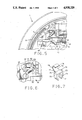
- FIG. 5 illustrates operation of the brake illustrated in FIG. 1 at elevated temperature conditions
- FIG. 6 is an enlargement of a portion of FIG. 5;
- FIG. 7 is a perspective view of the thermal elongating clip utilized the brake shown in FIG. 1.
- the drum brake 7 is associated with a drum 9 (shown in section) which is fixably connected with the wheel (not shown) of the vehicle.
- the drum brake 7 also has a plate 12 which is boltably connected to a flange of the axle housing of the vehicle. As shown is FIG. 1, the plate 12 is adapted for connection to the rear axle of the vehicle.
- Drum brake 7 is a leading trailing type brake. However, the present invention can be utilized on other drum brakes such as dual servo.
- Drum brake 7 has a primary (leading or front) shoe 10 and a secondary (trailing or rear) shoe 20.
- a wheel cylinder 14 In contact with the brake shoes 10, 20 and mounted by the plate means 12 is a wheel cylinder 14 and its associated pistons. Also connected with the brake shoes 10, 20 is a horse shoe return spring 16. For movement of the brake shoes 10, 20 outward, the pistons wheel cylinder 14 are actuated outward. The brake shoes 10, 20 pivot outward with relationship to the plate 12 by virtue of a bottom anchor 18. The return of the primary and secondary shoes inwardly after the wheel cylinder 14 has been relieved is accomplished by the horse shoe return spring 16. Each brake shoe is also mounted to the back plate 12 by virtue of a hold down cup and spring (not shown).
- Adjustably setting the distance between the brake shoes 10, 20 along the upper end is an adjuster strut 30.
- the adjuster strut 30 has at one end a head 32 with a rotatably mounted star wheel 34.
- the star wheel 34 is fixably connected with a bolt 36.
- the bolt 36 is received in an inner threaded sleeve nut 38 and rotation of the bolt 36 via the star wheel 34 causes the bolt 36 to be threadably removed from the threaded nut 38.
- the threaded nut 38 has two fingers 39 (only one shown) which capture the webbing of the secondary brake shoe 20 and a parking brake lever 21 and fit within slots 37 of the same (not shown).
- the head 32 has two fingers 41 which capture the webbing of the primary brake shoe 10 and fit within a slot 13 of the primary brake shoe (FIG. 3).
- an adjuster pawl 60 To turn the star wheel 34 upon actuation of the brakes by the wheel cylinder 14 there is provided an adjuster pawl 60.
- the adjuster pawl 60 has a tip 63 for making contact with the star wheel 34.
- the adjuster pawl 60 is also captured between the fingers 41 of the adjuster strut head and makes contact with the same via surface 65 (FIG. 4).
- the adjuster pawl 60 as illustrated has a flaring 62 projecting generally perpendicular from the main body of the adjuster pawl 60.
- the primary shoe 10 has an aperture 80 for receipt of the inserted flaring 62 of the adjuster pawl with a pivotal contact surface 82 for a rounded portion of the adjuster pawl flaring 69.
- the contact surface 82 allows the adjuster pawl 60 by its flaring 62 to be pivotally mounted with respect to the primary brake shoe 10.
- a stop means or thermal clip 70 has a spring clip connector portion 74 with a flat 75 which projects into the aperture 80 with legs 73 adjacent the webbing of the primary shoe 10.
- Lower clip section 71 locks the thermal clip 70 to the primary shoe 10.
- the other embodiments of the present invention may have the clip 70 connected to the shoe 10 by a fastener.
- a bimetallic hook to column portion 72 of the clip 70 has a linear portion 77 which is adjacent a surface 83 of the aperture 80. When heated to a predetermined temperature curved portion 79 of the hook angularly extends to the position shown in FIGS. 6 and 5.
- the hook portion is usually comprised of bimetallic or a shape memory effect material and will typically extend outward to design criteria at 300 degrees. However, in normal circumstances, even when extended hooked portion 79 is extended by the head of the brake 7, hooked portion 79 will not make contact with adjuster flaring 62 when the cylinder 14 is nonactivated.
- Coil spring 90 is connected between the primary 10 and secondary 20 brake shoes above the adjuster strut 30 and provides a compliant means of biasing of the adjuster pawl 60 against the star wheel 34.
- the spring 90 biases the adjuster pawl 60 to push upward (as shown by the arrow of FIG. 4) on the star wheel 34. It is noted that by placing the adjuster pawl spring 90 below the point of pivotal connection of the adjuster pawl 60 with the primary brake 10 shoe causes the spring 90 to aid the return spring 16.
- the adjuster strut 30 will be set at the factory to determine the minimum distance between the primary 10 and secondary 20 brake shoes when the wheel cylinder 14 is not actuated.
- the primary 10 and secondary 20 shoes Upon actuation of the brake 7 when the vehicle is moving in a predetermined direction the primary 10 and secondary 20 shoes will be pushed outward by the wheel cylinder 14 causing the shoe linings 13 to contact the wheel drum 9.
- the adjuster pawl 60 which is spring biased against the star wheel 31 will pivot tip 63 upward a slight or insignificant amount since the adjuster pawl surface 65 is in contact with the webbing of the fingers 41 of the strut. Therefore, the star wheel 34 will not be rotated.
- the adjuster pawl surface 65 will be further away from the fingers of the webbing of the adjuster fingers 65 allowing the spring 90 to cause the adjuster pawl 60 to pivot as shown (FIGS. 3 and 4) counterclockwise on the star wheel 34, causing the star wheel 34 (and connected bolt 36) to be rotated outward from the threaded nut 38 lengthening the strut 30. Therefore, the minimum distance between the primary 10 and secondary 20 shoes will be adjusted outward. The adjustment of the length of strut 30 will occur when the wheel cylinder 14 is activated with the vehicle proceeding in a forward or rearward direction.
- the clip 70 has an end surface 76 which makes contact with the adjuster pawl flaring 62 when the curved portion 79 extends. Therefore, the force transmitted between the clip 70 and the adjuster pawl flaring 62 will tend to travel through curved portion 79 as a force transmitted through a column.
- curved portion 79 can be configured in a manner that end surface 76 will perpendicularly contact the adjuster pawl flaring 62 to maximize the column force transmittal effect.
- the thermal clip curved portion 79 Upon a reduction in temperature of the brake 7 the thermal clip curved portion 79 will retract to the previous position to again allow pivotal movement of the adjuster pawl 60 to allow adjustment of the strut 30.
- the present invention is advantageous in that the clip 70 does not make contact with the star wheel 34 or with nuts 36. Contact between the adjuster pawl 60 and the star wheel 34 is virtually or completely eliminated when the brake 7 is heated. Instead of having a part with very close tolerances, the addition simple clip 70 can be utilized to thermal compensate the adjuster mechanism of the brake. Additionally the thermal clip 70 does not have to project a force against the adjuster pawl 60 but rather acts as a wedge preventing movement of the pawl 60 (only upon activation of the wheel cylinder 14). Therefore, the thermal elongating portion or hook 69 does not have to provide a force which continually overcome the force of spring 90 to prevent pivotal movement of the adjuster pawl 60.
- the present invention provides a method including of thermally compensating a self-adjusting vehicle wheel drum brake 7 with primary 10 and secondary 20 shoes, one of the shoes having an aperture 80 with a pivoting surface 82, the method including the following steps:
- an adjuster strut 30 including a star wheel 34 to set the distance between the shoes 10, 20;
Abstract
Description
Claims (5)
Priority Applications (1)
| Application Number | Priority Date | Filing Date | Title |
|---|---|---|---|
| US07/295,273 US4938320A (en) | 1989-01-10 | 1989-01-10 | Apparatus and method of utilization thereof of a thermal compensating self-adjusting vehicle wheel drum brake |
Applications Claiming Priority (1)
| Application Number | Priority Date | Filing Date | Title |
|---|---|---|---|
| US07/295,273 US4938320A (en) | 1989-01-10 | 1989-01-10 | Apparatus and method of utilization thereof of a thermal compensating self-adjusting vehicle wheel drum brake |
Publications (1)
| Publication Number | Publication Date |
|---|---|
| US4938320A true US4938320A (en) | 1990-07-03 |
Family
ID=23137001
Family Applications (1)
| Application Number | Title | Priority Date | Filing Date |
|---|---|---|---|
| US07/295,273 Expired - Lifetime US4938320A (en) | 1989-01-10 | 1989-01-10 | Apparatus and method of utilization thereof of a thermal compensating self-adjusting vehicle wheel drum brake |
Country Status (1)
| Country | Link |
|---|---|
| US (1) | US4938320A (en) |
Cited By (7)
| Publication number | Priority date | Publication date | Assignee | Title |
|---|---|---|---|---|
| GB2256463A (en) * | 1991-06-08 | 1992-12-09 | Gen Motors France | Drum brake and wear adjuster therefor. |
| US20030183465A1 (en) * | 2002-03-27 | 2003-10-02 | Takashi Ikeda | Drum brake device with an automatic shoe clearance adjustment apparatus |
| US20050262840A1 (en) * | 2004-05-27 | 2005-12-01 | Zf Friedrichshafen Ag | Hydraulic actuation apparatus for a motor vehicle clutch |
| US20050274580A1 (en) * | 2004-06-14 | 2005-12-15 | Delphi Technologies, Inc. | Shape memory alloy actuator |
| US7178642B1 (en) | 2005-01-20 | 2007-02-20 | Robert Bosch Gmbh | Drum brake |
| US7270220B1 (en) * | 2005-10-14 | 2007-09-18 | Robert Bosch, Gmbh | Thermo clip in an adjustor mechanism for a drum brake |
| JP2016176574A (en) * | 2015-03-20 | 2016-10-06 | 日信工業株式会社 | Brake device for vehicle |
Citations (17)
| Publication number | Priority date | Publication date | Assignee | Title |
|---|---|---|---|---|
| US2034922A (en) * | 1934-02-23 | 1936-03-24 | Hydraulic Brake Co | Brake |
| US2072014A (en) * | 1931-09-12 | 1937-02-23 | Thermo Brakes Corp | Automatic brake adjusting mechanism |
| US2101425A (en) * | 1935-08-08 | 1937-12-07 | Soc D Freins Hydrauliques S De | Braking device for rotating machine parts |
| US2140971A (en) * | 1935-12-18 | 1938-12-20 | Bendix Prod Corp | Brake |
| US2287238A (en) * | 1939-11-20 | 1942-06-23 | Bendix Aviat Corp | Brake |
| US2292018A (en) * | 1941-04-10 | 1942-08-04 | Thermo Brakes Corp | Brake adjuster |
| US2570398A (en) * | 1948-03-15 | 1951-10-09 | Thermo Brakes Corp | Automatic adjusting mechanism for brakes |
| US2873006A (en) * | 1957-09-11 | 1959-02-10 | Phillips Roy | Brake adjustment mechanism |
| US3068964A (en) * | 1960-06-17 | 1962-12-18 | Rockwell Standard Co | Automatic brake adjustment |
| US4148380A (en) * | 1976-12-20 | 1979-04-10 | Tokico Ltd. | Automatic shoe clearance adjusting device in shoe drum brake |
| US4223765A (en) * | 1978-09-28 | 1980-09-23 | The Bendix Corporation | Drum brake having pawl and lever |
| GB2060094A (en) * | 1979-05-21 | 1981-04-29 | Lucas Industries Ltd | Automatic adjusters for drum brakes |
| GB2088977A (en) * | 1980-12-06 | 1982-06-16 | Lucas Industries Ltd | Automatic adjuster for a shoe drum brake |
| US4385681A (en) * | 1979-05-21 | 1983-05-31 | Lucas Industries Limited | Drum brakes having automatic adjusters |
| US4706783A (en) * | 1984-09-14 | 1987-11-17 | Lucas Industries Public Limited Company | Automatic adjusting device for a brake |
| US4706784A (en) * | 1985-09-03 | 1987-11-17 | General Motors Corporation | Drum brake adjusters |
| US4804072A (en) * | 1987-02-12 | 1989-02-14 | Bendix France | Drum brake with automatic adjustment locked at high temperature |
-
1989
- 1989-01-10 US US07/295,273 patent/US4938320A/en not_active Expired - Lifetime
Patent Citations (18)
| Publication number | Priority date | Publication date | Assignee | Title |
|---|---|---|---|---|
| US2072014A (en) * | 1931-09-12 | 1937-02-23 | Thermo Brakes Corp | Automatic brake adjusting mechanism |
| US2034922A (en) * | 1934-02-23 | 1936-03-24 | Hydraulic Brake Co | Brake |
| US2101425A (en) * | 1935-08-08 | 1937-12-07 | Soc D Freins Hydrauliques S De | Braking device for rotating machine parts |
| US2140971A (en) * | 1935-12-18 | 1938-12-20 | Bendix Prod Corp | Brake |
| US2287238A (en) * | 1939-11-20 | 1942-06-23 | Bendix Aviat Corp | Brake |
| US2292018A (en) * | 1941-04-10 | 1942-08-04 | Thermo Brakes Corp | Brake adjuster |
| US2570398A (en) * | 1948-03-15 | 1951-10-09 | Thermo Brakes Corp | Automatic adjusting mechanism for brakes |
| US2873006A (en) * | 1957-09-11 | 1959-02-10 | Phillips Roy | Brake adjustment mechanism |
| US3068964A (en) * | 1960-06-17 | 1962-12-18 | Rockwell Standard Co | Automatic brake adjustment |
| US4148380A (en) * | 1976-12-20 | 1979-04-10 | Tokico Ltd. | Automatic shoe clearance adjusting device in shoe drum brake |
| US4223765A (en) * | 1978-09-28 | 1980-09-23 | The Bendix Corporation | Drum brake having pawl and lever |
| GB2060094A (en) * | 1979-05-21 | 1981-04-29 | Lucas Industries Ltd | Automatic adjusters for drum brakes |
| US4385681A (en) * | 1979-05-21 | 1983-05-31 | Lucas Industries Limited | Drum brakes having automatic adjusters |
| US4390086A (en) * | 1979-05-21 | 1983-06-28 | Lucas Industries Limited | Automatic adjusters for drum brakes |
| GB2088977A (en) * | 1980-12-06 | 1982-06-16 | Lucas Industries Ltd | Automatic adjuster for a shoe drum brake |
| US4706783A (en) * | 1984-09-14 | 1987-11-17 | Lucas Industries Public Limited Company | Automatic adjusting device for a brake |
| US4706784A (en) * | 1985-09-03 | 1987-11-17 | General Motors Corporation | Drum brake adjusters |
| US4804072A (en) * | 1987-02-12 | 1989-02-14 | Bendix France | Drum brake with automatic adjustment locked at high temperature |
Cited By (13)
| Publication number | Priority date | Publication date | Assignee | Title |
|---|---|---|---|---|
| US5246090A (en) * | 1991-06-08 | 1993-09-21 | General Motors France | Drum brake and wear adjuster therefor |
| GB2256463B (en) * | 1991-06-08 | 1994-12-07 | Gen Motors France | Drum brake and wear adjuster therefor |
| GB2256463A (en) * | 1991-06-08 | 1992-12-09 | Gen Motors France | Drum brake and wear adjuster therefor. |
| US7131519B2 (en) * | 2002-03-27 | 2006-11-07 | Nisshinbo Industries, Inc. | Drum brake device with an automatic shoe clearance adjustment apparatus |
| US20030183465A1 (en) * | 2002-03-27 | 2003-10-02 | Takashi Ikeda | Drum brake device with an automatic shoe clearance adjustment apparatus |
| US6877589B2 (en) * | 2002-03-27 | 2005-04-12 | Nisshinbo Ind. Inc. | Drum brake device with an automatic shoe clearance adjustment apparatus |
| US20060151264A1 (en) * | 2002-03-27 | 2006-07-13 | Nisshinbo Industries, Inc. | Drum brake device with an automatic shoe clearance adjustment apparatus |
| US20050262840A1 (en) * | 2004-05-27 | 2005-12-01 | Zf Friedrichshafen Ag | Hydraulic actuation apparatus for a motor vehicle clutch |
| US20050274580A1 (en) * | 2004-06-14 | 2005-12-15 | Delphi Technologies, Inc. | Shape memory alloy actuator |
| US7481054B2 (en) | 2004-06-14 | 2009-01-27 | Delphi Technologies, Inc. | Shape memory alloy actuator |
| US7178642B1 (en) | 2005-01-20 | 2007-02-20 | Robert Bosch Gmbh | Drum brake |
| US7270220B1 (en) * | 2005-10-14 | 2007-09-18 | Robert Bosch, Gmbh | Thermo clip in an adjustor mechanism for a drum brake |
| JP2016176574A (en) * | 2015-03-20 | 2016-10-06 | 日信工業株式会社 | Brake device for vehicle |
Similar Documents
| Publication | Publication Date | Title |
|---|---|---|
| US4148380A (en) | Automatic shoe clearance adjusting device in shoe drum brake | |
| US4385681A (en) | Drum brakes having automatic adjusters | |
| US4729457A (en) | Automatically adjustable and thermally lockable strut for a drum brake | |
| US4390086A (en) | Automatic adjusters for drum brakes | |
| US4938320A (en) | Apparatus and method of utilization thereof of a thermal compensating self-adjusting vehicle wheel drum brake | |
| JPS6256634A (en) | Drum brake-adjuster | |
| US5246090A (en) | Drum brake and wear adjuster therefor | |
| US4476963A (en) | Automatic adjuster for a shoe drum brake | |
| US6508339B2 (en) | Drum brake device having a shoe clearance over-adjustment prevention apparatus | |
| JPS5837309A (en) | Automatic locking and adjusting device | |
| US4394892A (en) | Automated braking-gap adjuster system for mechanical drum brake | |
| US5038898A (en) | Drum brake | |
| US3034603A (en) | Automatic brake adjuster | |
| US5158160A (en) | Automatic adjusting apparatus for a duo-servo drum brake | |
| US2060429A (en) | Brake mechanism | |
| US5000296A (en) | Self-adjusting vehicle wheel drum brake with multiple pawl step | |
| GB2088977A (en) | Automatic adjuster for a shoe drum brake | |
| JPS6145085B2 (en) | ||
| US4250980A (en) | Drum brake adjuster | |
| US6345702B1 (en) | Brake adjusters | |
| GB2151319A (en) | Automatic adjuster for a shoe drum brake | |
| US2308885A (en) | Brake | |
| JPH032015Y2 (en) | ||
| EP0905401A2 (en) | Drum brake device | |
| JPS627870Y2 (en) |
Legal Events
| Date | Code | Title | Description |
|---|---|---|---|
| AS | Assignment |
Owner name: GENERAL MOTORS CORPORATION, DETROIT, MI, A CORP. O Free format text: ASSIGNMENT OF ASSIGNORS INTEREST.;ASSIGNORS:HYDE, ROBERT W.;BROOKS, FRANK W. SR.;REEL/FRAME:005057/0355 Effective date: 19890307 |
|
| STCF | Information on status: patent grant |
Free format text: PATENTED CASE |
|
| FEPP | Fee payment procedure |
Free format text: PAYOR NUMBER ASSIGNED (ORIGINAL EVENT CODE: ASPN); ENTITY STATUS OF PATENT OWNER: LARGE ENTITY |
|
| FPAY | Fee payment |
Year of fee payment: 4 |
|
| SULP | Surcharge for late payment | ||
| REMI | Maintenance fee reminder mailed | ||
| FPAY | Fee payment |
Year of fee payment: 8 |
|
| FPAY | Fee payment |
Year of fee payment: 12 |
|
| AS | Assignment |
Owner name: DELPHI TECHNOLOGIES INC., MICHIGAN Free format text: ASSIGNMENT OF ASSIGNORS INTEREST;ASSIGNOR:GENERAL MOTORS CORPORATION;REEL/FRAME:022299/0156 Effective date: 19990101 |