EP3980306B1 - Raddrehzahlsensor für ein nutzfahrzeug - Google Patents
Raddrehzahlsensor für ein nutzfahrzeug Download PDFInfo
- Publication number
- EP3980306B1 EP3980306B1 EP20732147.2A EP20732147A EP3980306B1 EP 3980306 B1 EP3980306 B1 EP 3980306B1 EP 20732147 A EP20732147 A EP 20732147A EP 3980306 B1 EP3980306 B1 EP 3980306B1
- Authority
- EP
- European Patent Office
- Prior art keywords
- wheel speed
- speed sensor
- sensor
- component
- housing
- Prior art date
- Legal status (The legal status is an assumption and is not a legal conclusion. Google has not performed a legal analysis and makes no representation as to the accuracy of the status listed.)
- Active
Links
Images


Classifications
-
- G—PHYSICS
- G01—MEASURING; TESTING
- G01P—MEASURING LINEAR OR ANGULAR SPEED, ACCELERATION, DECELERATION, OR SHOCK; INDICATING PRESENCE, ABSENCE, OR DIRECTION, OF MOVEMENT
- G01P1/00—Details of instruments
- G01P1/006—Details of instruments used for thermal compensation
-
- B—PERFORMING OPERATIONS; TRANSPORTING
- B60—VEHICLES IN GENERAL
- B60T—VEHICLE BRAKE CONTROL SYSTEMS OR PARTS THEREOF; BRAKE CONTROL SYSTEMS OR PARTS THEREOF, IN GENERAL; ARRANGEMENT OF BRAKING ELEMENTS ON VEHICLES IN GENERAL; PORTABLE DEVICES FOR PREVENTING UNWANTED MOVEMENT OF VEHICLES; VEHICLE MODIFICATIONS TO FACILITATE COOLING OF BRAKES
- B60T17/00—Component parts, details, or accessories of power brake systems not covered by groups B60T8/00, B60T13/00 or B60T15/00, or presenting other characteristic features
- B60T17/18—Safety devices; Monitoring
- B60T17/22—Devices for monitoring or checking brake systems; Signal devices
- B60T17/221—Procedure or apparatus for checking or keeping in a correct functioning condition of brake systems
-
- G—PHYSICS
- G01—MEASURING; TESTING
- G01P—MEASURING LINEAR OR ANGULAR SPEED, ACCELERATION, DECELERATION, OR SHOCK; INDICATING PRESENCE, ABSENCE, OR DIRECTION, OF MOVEMENT
- G01P1/00—Details of instruments
- G01P1/02—Housings
- G01P1/026—Housings for speed measuring devices, e.g. pulse generator
-
- G—PHYSICS
- G01—MEASURING; TESTING
- G01P—MEASURING LINEAR OR ANGULAR SPEED, ACCELERATION, DECELERATION, OR SHOCK; INDICATING PRESENCE, ABSENCE, OR DIRECTION, OF MOVEMENT
- G01P3/00—Measuring linear or angular speed; Measuring differences of linear or angular speeds
- G01P3/42—Devices characterised by the use of electric or magnetic means
- G01P3/44—Devices characterised by the use of electric or magnetic means for measuring angular speed
- G01P3/48—Devices characterised by the use of electric or magnetic means for measuring angular speed by measuring frequency of generated current or voltage
- G01P3/481—Devices characterised by the use of electric or magnetic means for measuring angular speed by measuring frequency of generated current or voltage of pulse signals
- G01P3/487—Devices characterised by the use of electric or magnetic means for measuring angular speed by measuring frequency of generated current or voltage of pulse signals delivered by rotating magnets
-
- G—PHYSICS
- G01—MEASURING; TESTING
- G01P—MEASURING LINEAR OR ANGULAR SPEED, ACCELERATION, DECELERATION, OR SHOCK; INDICATING PRESENCE, ABSENCE, OR DIRECTION, OF MOVEMENT
- G01P3/00—Measuring linear or angular speed; Measuring differences of linear or angular speeds
- G01P3/42—Devices characterised by the use of electric or magnetic means
- G01P3/44—Devices characterised by the use of electric or magnetic means for measuring angular speed
- G01P3/48—Devices characterised by the use of electric or magnetic means for measuring angular speed by measuring frequency of generated current or voltage
- G01P3/481—Devices characterised by the use of electric or magnetic means for measuring angular speed by measuring frequency of generated current or voltage of pulse signals
- G01P3/488—Devices characterised by the use of electric or magnetic means for measuring angular speed by measuring frequency of generated current or voltage of pulse signals delivered by variable reluctance detectors
Definitions
- the invention relates to a wheel speed sensor for a commercial vehicle, in particular a wheel speed sensor for a commercial vehicle, which is arranged in the area of a brake of a wheel on a chassis of the commercial vehicle.
- a detection of wheel speeds of individual wheels of vehicles is necessary today, in particular to enable a function of assistance systems, such as ABS, ASR or ESP. Accurate measurement of the wheel speed is required in order to activate appropriate algorithms in borderline situations.
- Wheel speed sensors are known in order to precisely detect the wheel speeds, which are arranged in the area of a wheel of the vehicle in order to detect the speed as directly as possible, without deviations due to a mechanical transmission.
- Active wheel speed sensors ie wheel speed sensors that are activated by applying a supply voltage and generate an output signal
- the active wheel speed sensors already generate signals in the wheel speed sensor which, for example, have a constant amplitude that is independent of the speed.
- a data protocol is thus already generated in the wheel speed sensor, which can be evaluated in a control unit, for example transmitted via a bus system. It is also possible to implement diagnostic functions.
- CN 204154733 U discloses a wheel speed sensor having an active pulse sensor.
- the pulse sensor is enclosed in a housing that has a protective cap that partially covers the housing.
- CN 104020311A discloses a sensor usable in a high temperature environment.
- the sensor has a transition tube into which a main circuit board of the sensor is inserted.
- the invention is therefore based on the object of eliminating the above disadvantage and providing an active wheel speed sensor which can also be used in an area with a higher thermal load.
- a wheel speed sensor for a commercial vehicle includes an active pulse sensor, a housing configured to at least partially enclose the active pulse sensor, and a protective cap at least partially covering the housing.
- the wheel speed sensor also has at least one component that is designed to adapt a temperature resistance of the wheel speed sensor such that the wheel speed sensor can be used in a high-temperature environment.
- the active pulse sensor is a sensor that detects pulses generated by a change in a magnetic field in a sensing area of the sensor.
- the magnetic field in the area of the sensor is changed either by introducing a magnetic body, for example a rotating magnet wheel with permanent magnets attached to it, into the detection area or by changing a stationary magnetic field in the area of the sensor.
- the stationary magnetic field is changed by introducing a ferromagnetic body into the detection area.
- a pulse wheel which has teeth and gaps on its circumference, is moved in the detection area of the sensor and the change in the magnetic field is recorded by the teeth and gaps moving through the detection area. Both a transition from a tooth to a gap and a transition from a gap to a tooth can be detected.
- wheel speed sensors can be arranged in the area of the wheel hubs, and thus in the area of the wheel brakes , whereby a function and a usual service life of wheel speed sensors with active pulse sensors is still guaranteed. Furthermore, additional functionalities, such as detecting the direction of rotation of one of the wheels, measuring an air gap between the pulse sensor and a magnet wheel, diagnostic functionality, such as for magnetic parameters, signal transmission with a parity bit, etc., can be implemented.
- the wheel speed sensor has an area between the active pulse sensor and an area surrounding the wheel speed sensor, which has a thermal insulation medium, which has a lower thermal conductivity than a thermal conductivity of a material of the housing, as the component in order to adapt the temperature resistance of the wheel speed sensor so that the wheel speed sensor in is operable in a high-temperature environment.
- thermal insulation material which has a lower thermal conductivity than the thermal conductivity of the material of the housing, heat is conducted more slowly between the active pulse sensor and the environment to heat-sensitive components and areas in which heat-sensitive components are arranged can be effectively protected against short-term excessive temperatures occurring in the high temperature environment.
- the wheel speed sensor has a closed cavity which is designed to enclose the thermal insulation medium therein.
- a closed cavity containing the thermal insulation medium can be easily manufactured and the thermal insulation medium can be easily introduced into the cavity as needed.
- the thermal insulation medium has air.
- Air for example ambient air in an assembly environment, is present in a cavity that is open prior to final assembly of the wheel speed sensor without further action and is therefore a favorable thermal insulation medium that can be used without additional effort.
- the wheel speed sensor has a number of closed cavities.
- an isolation property of the wheel speed sensor can be specified more precisely.
- insulation properties are further improved by reducing or eliminating convection.
- the plurality of closed cavities are arranged adjacent to one another.
- the cavities have a honeycomb structure, at least in some areas.
- honeycomb structure in which the multiple cavities are juxtaposed in two directions rather than in one direction, with the smallest possible gap between the cavities, further reduces the surface area of the wheel speed sensor material, which is better at conducting heat to vulnerable areas , in order to further increase the insulating effect.
- the wheel speed sensor has the cavity or cavities between an outer surface of the housing and an inner surface of the protective cap.
- This arrangement of the cavity or cavities means that the cavity or cavities are easy to manufacture, since indentations only have to be made in the outer surface of the housing or in the inner surface of the protective cap.
- the active pulse sensor has an AMR sensor as the component in order to adjust the temperature resistance of the wheel speed sensor so that the wheel speed sensor can be used in a high-temperature environment.
- An AMR sensor namely a sensor that has a chip with an “anisotropic magnetoresistive” effect, has high thermal resistance. This means that the wheel speed sensor can also be used in the high-temperature environment with a higher thermal load without major design measures.
- the AMR sensor is designed to detect a temperature of the wheel speed sensor.
- the temperature of the wheel speed sensor can be recorded without additional components.
- the wheel speed sensor 1 shows a juxtaposition of components of the wheel speed sensor 1 of a preferred embodiment of the invention.
- the wheel speed sensor 1 is used in a commercial vehicle, not shown. Alternatively, the wheel speed sensor 1 can also be used in other vehicles.
- the wheel speed sensor 1 has an active pulse sensor 2 and a housing 3 which partially encloses the active pulse sensor 2 .
- the housing 3 has a first component 4 made of plastic and a second component 5 made of the same plastic and connected to the first component 4 .
- Wheel speed sensor 1 also has a protective cap 6 that partially covers housing 3 .
- the housing 3 of the wheel speed sensor 1 is completely covered.
- these parts are shown in a side-by-side view.
- the first component 4 with the active pulse sensor 2 surrounded concentrically by the second component 5.
- the production takes place as follows:
- the first component 4 with pre-assembled elements, namely the active pulse sensor 2, busbars 9 and a connection cable 10, is cast with the same plastic from which the first component 4 was made, resulting in the second component 5. which encloses the first component 4 as it were.
- the first component 4 As in 1 is shown at the right end of the first component 4, this has a recess in order not to cover the active pulse sensor 2 completely. Alternatively, this cutout is not provided and the active pulse sensor 2 is completely enclosed by the housing 3 . In other alternative embodiments, not all of the preassembled elements are provided, or alternatively the first component 4 is not encapsulated, but instead, for example, a second component 5 consisting of several parts is slipped over the first component 4 and the parts are connected to one another, for example clipped. Alternatively, the same plastic is not used.
- the wheel speed sensor 1 has an area with a thermal insulation material that has a lower thermal conductivity than a thermal conductivity of a material of the housing 3, and thus forms the component with which the temperature resistance of the wheel speed sensor is can be adjusted that the wheel speed sensor is operational in a high temperature environment.
- the area with the thermal insulation material has, as in 2 , an enlarged view of a section of an outer surface of the second component 5 of the wheel speed sensor 1 from 1 , is shown in more detail, depressions 7 which are provided between the active pulse sensor 2 and an environment of the wheel speed sensor 1 and are open to the outside.
- the indentations 7 form a plurality of cavities between the outer surface of the second component 5 , ie the housing 3 , and an inner surface of the protective cap 6 .
- the wheel speed sensor 1 thereby has a plurality of closed cavities are arranged adjacent to each other.
- the casing 3 has the cavities in a honeycomb structure in which the cavities are juxtaposed in two directions and there is a minimum space between the cavities.
- the wheel speed sensor 1 does not have several, but only one cavity, which is designed in such a way that the active pulse sensor 3 is isolated from high temperatures so that the temperature resistance of the wheel speed sensor 1 is adapted so that the wheel speed sensor can be used in a high temperature environment is.
- the housing 3 does not have a honeycomb structure, or the cavities are not arranged adjacent to one another.
- the cavities between the outer surface of the housing 3 and the inner surface of the protective cap 6 are also or exclusively in the protective cap 6, or not between the outer surface of the housing 3 and the inner surface of the protective cap 6, but are, for example, completely within the material the protective cap 6 or the second component 5 of the housing 3 is provided.
- Air is enclosed in the cavities as a thermal insulation medium, which has a lower thermal conductivity than a thermal conductivity of the material of the housing 3 , in particular of the second component 5 .
- a different gas is trapped in the cavities, or liquids or solids of a different material than that of the housing 3.
- the active pulse sensor 2 has an AMR sensor as the component to adjust the temperature resistance of the wheel speed sensor so that the wheel speed sensor is operable in a high-temperature environment.
- the AMR sensor is designed to provide additional functionalities, namely detection of the direction of rotation of one of the wheels, measurement of an air gap between the momentum sensor and a magnet wheel, diagnostic functionality such as for magnetic parameters, signal transmission with a parity bit, and detection one wheel speed sensor temperature. In alternate embodiments, only one or some of the functionality is performed.
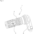
- FIG 3 shows a representation of the first component 4 of the wheel speed sensor 1 with the second component 5 cast around, with a radial cable outlet 8.
- FIG. 4 shows a representation of the wheel speed sensor 1 with a radial cable outlet with a fitted protective cap 6.
- a commercial vehicle has wheel speed sensor 1 .
- the wheel speed sensor 1 By providing the wheel speed sensor 1 with the active pulse sensor and the component that adapts the temperature resistance of the wheel speed sensor so that the wheel speed sensor can be used in the high-temperature environment, the additional functionalities of the active pulse sensor can be used in the commercial vehicle sector.
Landscapes
- Physics & Mathematics (AREA)
- General Physics & Mathematics (AREA)
- Engineering & Computer Science (AREA)
- Transportation (AREA)
- Mechanical Engineering (AREA)
- Regulating Braking Force (AREA)
- Force Measurement Appropriate To Specific Purposes (AREA)
- Transmission And Conversion Of Sensor Element Output (AREA)
- Valves And Accessory Devices For Braking Systems (AREA)
- Testing Or Calibration Of Command Recording Devices (AREA)
Description
- Die Erfindung betrifft einen Raddrehzahlsensor für ein Nutzfahrzeug, insbesondere einen Raddrehzahlsensor für ein Nutzfahrzeug, der im Bereich einer Bremse eines Rads an einem Fahrwerk des Nutzfahrzeugs angeordnet ist.
- Eine Erfassung von Raddrehzahlen von einzelnen Rädern von Fahrzeugen ist heutzutage erforderlich, um insbesondere eine Funktion von Assistenzsystemen, beispielsweise ABS, ASR oder ESP, zu ermöglichen. Dabei ist eine genaue Erfassung der Raddrehzahl erforderlich, um in Grenzsituationen entsprechende Algorithmen anzusteuern. Um die Raddrehzahlen genau zu erfassen, sind Raddrehzahlsensoren bekannt, die im Bereich eines Rads des Fahrzeugs angeordnet sind, um die Drehzahl möglichst unmittelbar, ohne Abweichungen durch eine mechanische Übertragung, zu erfassen.
- Im PKW-Bereich werden vermehrt aktive Raddrehzahlsensoren, also Raddrehzahlsensoren, die durch Anlegen einer Versorgungsspannung aktiviert werden und ein Ausgangssignal erzeugen, eingesetzt. Die aktiven Raddrehzahlsensoren erzeugen bereits im Raddrehzahlsensor Signale, die beispielsweise eine drehzahlunabhängige konstante Amplitude aufweisen. Somit wird bereits im Raddrehzahlsensor ein Datenprotokoll erzeugt, das, beispielsweise über ein Bus-System übertragen, in einem Steuergerät ausgewertet werden kann. Außerdem besteht die Möglichkeit, Diagnosefunktionen zu implementieren.
- Im Nutzfahrzeugbereich war ein Einsatz der aktiven Raddrehzahlsensoren und ein Ausnützen ihrer Vorteile bislang nicht möglich, da hier im Bereich des Rades eine thermische Belastung des Sensors größer als im PKW-Bereich ist und insbesondere Chips von Hall-Gebern der thermischen Belastung nicht standhalten.
- Im Dokument
CN 204154733 U ist ein Raddrehzahlsensor offenbart, der einen aktiven Impulssensor aufweist. Der Impulssensor wird von einem Gehäuse umschlossen, das eine Schutzkappe aufweist die das Gehäuse teilweise abdeckt. - In
CN 104020311 A ist ein Sensor offenbart, der in einer Hochtemperaturumgebung einsetzbar ist. Dazu weist der Sensor ein Übergangsrohr auf, in das eine Hauptplatine des Sensors eingebracht ist. - Der Erfindung liegt also die Aufgabe zugrunde, den obigen Nachteil zu beseitigen und einen aktiven Raddrehzahlsensor bereitzustellen, der auch in einem Bereich mit einer höheren thermischen Belastung eingesetzt werden kann.
- Die Aufgabe wird durch einen Raddrehzahlsensor gemäß Anspruch 1 gelöst. Vorteilhafte Weiterentwicklungen sind in den abhängigen Ansprüchen enthalten.
- Gemäß einem Aspekt der Erfindung weist ein Raddrehzahlsensor für ein Nutzfahrzeug einen aktiven Impulssensor, ein Gehäuse, das ausgebildet ist, den aktiven Impulssensor zumindest teilweise zu umschließen, und eine Schutzkappe, die das Gehäuse zumindest teilweise abdeckt, auf. Der Raddrehzahlsensor weist ferner mindestens ein Bauelement auf, das ausgebildet ist, eine Temperaturwiderstandsfähigkeit des Raddrehzahlsensors so anzupassen, dass der Raddrehzahlsensor in einer Hochtemperaturumgebung einsatzfähig ist.
- Der aktive Impulssensor ist ein Sensor, der Impulse erfasst, die durch eine Veränderung eines Magnetfelds in einem Erfassungsbereich des Sensors erzeugt werden. Die Veränderung des Magnetfelds im Bereich des Sensors erfolgt entweder durch Einbringen eines magnetischen Körpers, beispielsweise eines sich drehenden Polrads mit daran angebrachten Permanentmagneten, in den Erfassungsbereich oder durch Veränderung eines stationären Magnetfelds im Bereich des Sensors. Das stationäre Magnetfeld wird durch Einbringen eines ferromagnetischen Körpers in den Erfassungsbereich verändert. Hierbei wird ein Impulsrad, das am Umfang Zähne und Lücken aufweist, im Erfassungsbereich des Sensors bewegt und die Veränderung des Magnetfelds durch die sich durch den Erfassungsbereich bewegenden Zähne und Lücken erfasst. Dabei kann sowohl ein Übergang von einem Zahn zu einer Lücke als auch ein Übergang von einer Lücke zu einem Zahn erfasst werden.
- Im Unterschied zum PKW-Bereich treten im Nutzfahrzeugbereich beim Abbremsen im Bereich der Radbremsen höhere Temperaturen auf, da eine wesentlich höhere kinetische Energie hauptsächlich in Wärmeenergie umgewandelt wird. Da die Raddrehzahlsensoren, wie auch die Radbremsen der Nutzfahrzeuge, im Bereich von Radnaben des Nutzfahrzeugs angeordnet sind, gibt es somit eine wesentlich größer ist. Hierbei liegen in der Hochtemperaturumgebung zwar keine dauerhaften hohen Temperaturen vor, jedoch sind auftretende Spitzentemperaturen, insbesondere beim starken Abbremsen, höher als im PKW-Bereich.
- Durch den Einsatz von einem Bauelement, das ausgebildet ist, die Temperaturwiderstandsfähigkeit des Raddrehzahlsensors so anzupassen, dass der Raddrehzahlsensor in einer Hochtemperaturumgebung einsatzfähig ist, oder von mehreren solchen Bauelementen, können Raddrehzahlsensoren im Bereich der Radnaben, und damit in dem Bereich der Radbremsen, angeordnet sein, wobei eine Funktion und eine übliche Lebensdauer von Raddrehzahlsensoren mit aktiven Impulssensoren dennoch gewährleistet ist. Ferner können zusätzliche Funktionalitäten, wie etwa eine Erkennung der Drehrichtung eines der Räder, eine Messung eines Luftspalts zwischen dem Impulssensor und einem Polrad, eine Diagnosefunktionalität, wie etwa für magnetische Parameter, eine Signalübertragung mit einem Parity-Bit, etc., realisiert werden.
- Erfindungsgemäß weist der Raddrehzahlsensor zwischen dem aktiven Impulssensor und einer Umgebung des Raddrehzahlsensors einen Bereich, der ein thermisches Isolationsmedium, das eine geringere Wärmeleitfähigkeit als eine Wärmeleitfähigkeit eines Materials des Gehäuses besitzt, als das Bauelement, um die Temperaturwiderstandsfähigkeit des Raddrehzahlsensors so anzupassen, dass der Raddrehzahlsensor in einer Hochtemperaturumgebung einsatzfähig ist, auf.
- Durch diese Bereiche mit dem thermischen Isolationsmaterial, das eine geringere Wärmeleitfähigkeit als die Wärmeleitfähigkeit des Materials des Gehäuses hat, wird zwischen dem aktiven Impulssensor und der Umgebung Wärme langsamer zu wärmeempfindlichen Bauteilen geleitet und es können Bereiche, in denen wärmeempfindliche Bauteile angeordnet sind, wirksam gegen kurzzeitig auftretende übermäßige Temperaturen in der Hochtemperaturumgebung geschützt werden.
- Gemäß einer weiteren vorteilhaften Weiterbildung des Raddrehzahlsensors weist der Raddrehzahlsensor einen abgeschlossenen Hohlraum auf, der ausgebildet ist, das thermische Isolationsmedium darin einzuschließen.
- Ein abgeschlossener Hohlraum, der das thermische Isolationsmedium aufweist, kann einfach hergestellt werden und das thermische Isolationsmedium kann nach Bedarf einfach in den Hohlraum eingebracht werden.
- Bei einer weiteren vorteilhaften Weiterbildung des Raddrehzahlsensors weist das thermische Isolationsmedium Luft auf.
- Luft, beispielsweise Umgebungsluft in einer Montageumgebung, ist in einem vor einer endgültigen Montage des Raddrehzahlsensors offenen Hohlraum ohne weiteres Zutun vorhanden und ist somit ein günstiges thermisches Isolationsmedium, das ohne Mehraufwand verwendet werden kann.
- In einer weiteren vorteilhaften Weiterbildung des Raddrehzahlsensors weist der Raddrehzahlsensor mehrere abgeschlossene Hohlräume auf.
- Durch ein Vorsehen von mehreren abgeschlossenen Hohlräumen kann eine Isolationseigenschaft des Raddrehzahlsensors genauer festgelegt werden. Insbesondere bei der Verwendung von einem Gas, wie beispielsweise der Luft, als das thermische Isolationsmedium werden Isolationseigenschaften durch ein Verringern oder Beseitigen einer Konvektion weiter verbessert.
- Gemäß einer weiteren vorteilhaften Weiterbildung des Raddrehzahlsensors sind die mehreren abgeschlossenen Hohlräume zueinander benachbart angeordnet.
- Durch diese Anordnung kann eine Fläche eines Materials des Raddrehzahlsensors, das Wärme besser zu gefährdeten Bereichen leitet als das Isolationsmaterial, verringert werden, und so die Isolationswirkung verstärken.
- In einer weiteren vorteilhaften Weiterbildung des Raddrehzahlsensors weisen die Hohlräume zumindest bereichsweise eine Bienenwaben-Struktur auf.
- Durch die Bienenwabenstruktur, in der die mehreren Hohlräume nicht nur in einer Richtung, sondern in zwei Richtungen nebeneinander angeordnet sind und ein kleinstmöglicher Zwischenraum zwischen den Hohlräumen vorhanden ist, wird die Fläche des Materials des Raddrehzahlsensors, das Wärme besser zu gefährdeten Bereichen leitet, weiter verringert, um so die Isolationswirkung nochmals zu verstärken.
- Bei einer weiteren vorteilhaften Weiterbildung des Raddrehzahlsensors weist der Raddrehzahlsensor den Hohlraum oder die Hohlräume zwischen einer Außenfläche des Gehäuses und einer Innenfläche der Schutzkappe auf.
- Durch diese Anordnung des Hohlraums oder der Hohlräume ist der Hohlraum oder sind die Hohlräume einfach anzufertigen, da lediglich in die Außenfläche des Gehäuses oder in die Innenfläche der Schutzkappe Vertiefungen eingebracht werden müssen.
- Gemäß einer vorteilhaften Weiterbildung des Raddrehzahlsensors weist der aktive Impulssensor einen AMR-Sensor als das Bauelement, um die Temperaturwiderstandsfähigkeit des Raddrehzahlsensors so anzupassen, dass der Raddrehzahlsensor in einer Hochtemperaturumgebung einsatzfähig ist, auf.
- Ein AMR-Sensor, nämlich ein Sensor, der einen Chip mit einem "Anisotropen MagnetoResistiven" Effekt aufweist, weist eine große thermische Widerstandsfähigkeit auf. Damit kann der Raddrehzahlsensor auch ohne größere konstruktive Maßnahmen in der Hochtemperaturumgebung mit einer höheren thermischen Belastung eingesetzt werden.
- Entsprechend einer vorteilhaften Weiterbildung des Raddrehzahlsensors ist der AMR-Sensor ausgebildet ist, eine Temperatur des Raddrehzahlsensors zu erfassen.
- Bei der Verwendung des AMR-Sensors kann ohne zusätzliche Bauteile die Temperatur des Raddrehzahlsensors erfasst werden.
- Nachstehend wird die Erfindung anhand eines Ausführungsbeispiels unter Bezugnahme auf die beigefügten Zeichnungen erläutert.
- Insbesondere zeigt:
- Fig. 1
- eine Aneinanderreihung von Komponenten des erfindungsgemäßen Raddrehzahlsensors;
- Fig. 2
- eine vergrößerte Darstellung eines Ausschnitts einer Außenfläche eines zweiten Bauteils des Raddrehzahlsensors von
Fig. 1 ; - Fig. 3
- eine Darstellung eines mit dem zweiten Bauteil umgossenen ersten Bauteils des Raddrehzahlsensors mit radialem Kabelabgang; und
- Fig. 4
- eine Darstellung des Raddrehzahlsensors von
Fig. 3 mit montierter Schutzkappe. -
Fig. 1 zeigt eine Aneinanderreihung von Komponenten des Raddrehzahlsensors 1 einer bevorzugten Ausführungsform der Erfindung. Der Raddrehzahlsensor 1 wird in einem nicht gezeigten Nutzfahrzeug eingesetzt. Alternativ kann der Raddrehzahlsensor 1 auch in anderen Fahrzeugen eingesetzt werden. - Der Raddrehzahlsensor 1 weist einen aktiven Impulssensor 2 und ein Gehäuse 3, das den aktiven Impulssensor 2 teilweise umschließt, auf.
- Das Gehäuse 3 weist ein erstes Bauteil 4 aus Kunststoff und ein mit dem ersten Bauteil 4 verbundenes zweites Bauteil 5 aus dem gleichen Kunststoff auf. Ferner weist der Raddrehzahlsensor 1 eine Schutzkappe 6 auf, die das Gehäuse 3 teilweise abdeckt. In einer alternativen Ausführungsform wird das Gehäuse 3 des Raddrehzahlsensors 1 vollständig abgedeckt. In
Fig. 1 sind diese Teile in einer nebeneinander angeordneten Darstellung gezeigt. Tatsächlich ist in der endgültigen Form das erste Bauteil 4 mit dem aktiven Impulssensor 2 von dem zweiten Bauteil 5 konzentrisch umschlossen. Die Herstellung geschieht wie folgt: Das erste Bauteil 4 mit vormontierten Elementen, nämlich dem aktiven Impulssensor 2, Stromschienen 9 und einem Anschlusskabel 10, wird mit demselben Kunststoff, aus dem das erste Bauteil 4 hergestellt wurde, umgossen, wodurch das zweite Bauteil 5 entsteht, das das erste Bauteil 4 quasi umhüllt. Wie inFig. 1 am rechten Ende des ersten Bauteils 4 gezeigt ist, weist dieses eine Aussparung auf, um den aktiven Impulssensor 2 nicht vollständig abzudecken. Alternativ ist diese Aussparung nicht vorgesehen, und der aktive Impulssensor 2 ist von dem Gehäuse 3 vollständig umschlossen. In weiteren alternativen Ausführungsformen sind nicht sämtliche vormontierten Elemente vorgesehen, oder das erste Bauteil 4 wird alternativ nicht umgossen, sondern beispielsweise wird ein aus mehreren Teilen bestehendes zweites Bauteil 5 über das erste Bauteil 4 gestülpt und die Teile werden miteinander verbunden, beispielsweise geklipst. Alternativ wird nicht der gleiche Kunststoff verwendet. - Der Raddrehzahlsensor 1 weist zwischen dem aktiven Impulssensor 2 und einer Umgebung des Raddrehzahlsensors 1 einen Bereich mit einem thermischen Isolationsmaterial auf, das eine geringere Wärmeleitfähigkeit als eine Wärmeleitfähigkeit eines Materials des Gehäuses 3 hat, und bildet damit das Bauelement, mit dem die Temperaturwiderstandsfähigkeit des Raddrehzahlsensors so angepasst werden kann, dass der Raddrehzahlsensor in einer Hochtemperaturumgebung einsatzfähig ist.
- Der Bereich mit dem thermischen Isolationsmaterial weist, wie in
Fig. 2 , einer vergrößerten Darstellung eines Ausschnitts einer Außenfläche des zweiten Bauteils 5 des Raddrehzahlsensors 1 vonFig. 1 , genauer gezeigt ist, Vertiefungen 7 auf, die zwischen dem aktiven Impulssensor 2 und einer Umgebung des Raddrehzahlsensors 1 vorgesehen sind und nach außen hin offen sind. - Durch die Vertiefungen 7 werden, wenn die Schutzkappe 6 auf dem Gehäuse 3 montiert ist, mehrere Hohlräume zwischen der Außenfläche des zweiten Bauteils 5, also des Gehäuses 3, und einer Innenfläche der Schutzkappe 6 gebildet. Der Raddrehzahlsensor 1 weist dadurch mehrere abgeschlossene Hohlräume auf, die zueinander benachbart angeordnet sind. Insbesondere weist das Gehäuse 3 die Hohlräume in einer Bienenwaben-Struktur, in der die Hohlräume in zwei Richtungen nebeneinander angeordnet sind und ein kleinstmöglicher Zwischenraum zwischen den Hohlräumen vorhanden ist, auf.
- In alternativen Ausführungsformen weist der Raddrehzahlsensor 1 nicht mehrere, sondern nur einen Hohlraum auf, der so ausgebildet ist, dass der aktive Impulssensor 3 von hohen Temperaturen so isoliert ist, dass die Temperaturwiderstandsfähigkeit des Raddrehzahlsensors 1 so angepasst ist, dass der Raddrehzahlsensor in einer Hochtemperaturumgebung einsatzfähig ist. In weiteren alternativen Ausführungsformen weist das Gehäuse 3 keine Bienenwaben-Struktur auf, oder die Hohlräume sind nicht zueinander benachbart angeordnet. In anderen alternativen Ausführungsformen sind die Hohlräume zwischen der Außenfläche des Gehäuses 3 und der Innenfläche der Schutzkappe 6 auch oder ausschließlich in der Schutzkappe 6, oder nicht zwischen der Außenfläche des Gehäuses 3 und der Innenfläche der Schutzkappe 6 angeordnet, sondern sind beispielsweise vollständig innerhalb des Materials der Schutzkappe 6 oder des zweiten Bauteils 5 des Gehäuses 3 vorgesehen.
- In den Hohlräumen ist Luft als ein thermisches Isolationsmedium, das eine geringere Wärmeleitfähigkeit als eine Wärmeleitfähigkeit des Materials des Gehäuses 3, insbesondere des zweiten Bauteils 5, hat, eingeschlossen. In alternativen Ausführungsformen ist ein anderes Gas in den Hohlräumen eingeschlossen, oder Flüssigkeiten oder Feststoffe aus einem anderen Material als das des Gehäuses 3.
- Der aktive Impulssensor 2 weist einen AMR-Sensor als das Bauelement, um die Temperaturwiderstandsfähigkeit des Raddrehzahlsensors so anzupassen, dass der Raddrehzahlsensor in einer Hochtemperaturumgebung einsatzfähig ist, auf.
- Der AMR-Sensor ist ausgebildet, zusätzliche Funktionalitäten, nämlich eine Erkennung der Drehrichtung eines der Räder, eine Messung eines Luftspalts zwischen dem Impulssensor und einem Polrad, eine Diagnosefunktionalität, wie etwa für magnetische Parameter, eine Signalübertragung mit einem Parity-Bit, und eine Erfassung einer Temperatur des Raddrehzahlsensors, auszuführen. In alternativen Ausführungsformen wird nur eine oder werden lediglich einige der Funktionalitäten ausgeführt.
-
Fig. 3 zeigt eine Darstellung des mit dem zweiten Bauteil 5 umgossenen ersten Bauteils 4 des Raddrehzahlsensors 1 mit radialem Kabelabgang 8. -
Fig. 4 zeigt eine Darstellung des Raddrehzahlsensors 1 mit radialem Kabelabgang mit montierter Schutzkappe 6. - Weiterhin weist ein Nutzfahrzeug den Raddrehzahlsensor 1 auf. Durch das Vorsehen des Raddrehzahlsensors 1 mit dem aktiven Impulssensor und dem Bauelement, das die Temperaturwiderstandsfähigkeit des Raddrehzahlsensors so anpasst, dass der Raddrehzahlsensor in der Hochtemperaturumgebung einsatzfähig ist, können die zusätzlichen Funktionalitäten des aktiven Impulssensors im Nutzfahrzeugbereich genutzt werden.
- Alle in der Beschreibung, den nachfolgenden Ansprüchen und der Zeichnung dargestellten Merkmale können sowohl einzeln als auch in beliebiger Kombination miteinander erfindungswesentlich sein
-
- 1
- Raddrehzahlsensor
- 2
- aktiver Impulssensor
- 3
- Gehäuse
- 4
- erstes Bauteil
- 5
- zweites Bauteil
- 6
- Schutzkappe
- 7
- Vertiefung
- 8
- radialer Kabelabgang
- 9
- Stromschiene
- 10
- Anschlusskabel
Claims (9)
- Raddrehzahlsensor (1) für ein Nutzfahrzeug, aufweisendeinen aktiven Impulssensor (2),ein Gehäuse (3), das ausgebildet ist, den aktiven Impulssensor (2) zumindest teilweise zu umschließen, undeine Schutzkappe (6), die das Gehäuse (3) zumindest teilweise abdeckt,dadurch gekennzeichnet, dassder Raddrehzahlsensor (1) mindestens ein Bauelement aufweist, das ausgebildet ist, eine Temperaturwiderstandsfähigkeit des Raddrehzahlsensors so anzupassen, dass der Raddrehzahlsensor in einer Hochtemperaturumgebung einsatzfähig ist,wobeider Raddrehzahlsensor (1) zwischen dem aktiven Impulssensor (2) und einer Umgebung des Raddrehzahlsensors (1) einen Bereich, der ein thermisches Isolationsmedium aufweist, das eine geringere Wärmeleitfähigkeit als eine Wärmeleitfähigkeit eines Materials des Gehäuses (3) besitzt, als das Bauelement aufweist, um die Temperaturwiderstandsfähigkeit des Raddrehzahlsensors so anzupassen, dass der Raddrehzahlsensor in einer Hochtemperaturumgebung einsatzfähig ist,.
- Raddrehzahlsensor (1) gemäß Anspruch 1, wobei
der Raddrehzahlsensor (1) einen abgeschlossenen Hohlraum aufweist, der ausgebildet ist, das thermische Isolationsmedium darin einzuschließen. - Raddrehzahlsensor gemäß Anspruch 2, wobei
das thermische Isolationsmedium Luft aufweist. - Raddrehzahlsensor (1) gemäß Anspruch 2 oder 3, wobei
der Raddrehzahlsensor (1) mehrere abgeschlossene Hohlräume aufweist. - Raddrehzahlsensor (1) gemäß Anspruch 4, wobei die mehreren abgeschlossenen Hohlräume zueinander benachbart angeordnet sind.
- Raddrehzahlsensor (1) gemäß Anspruch 5, wobei
die Hohlräume zumindest bereichsweise eine Bienenwaben-Struktur aufweisen. - Raddrehzahlsensor (1) gemäß einem der Ansprüche 2 bis 6, wobei
der Hohlraum oder die Hohlräume zwischen einer Außenfläche des Gehäuses (3) und einer Innenfläche der Schutzkappe (6) vorgesehen sind. - Raddrehzahlsensor (1) gemäß einem der vorangehenden Ansprüche, wobei
der aktive Impulssensor (2) einen AMR-Sensor als das Bauelement, um die Temperaturwiderstandsfähigkeit des Raddrehzahlsensors so anzupassen, dass der Raddrehzahlsensor in einer Hochtemperaturumgebung einsatzfähig ist, aufweist. - Raddrehzahlsensor (1) gemäß Anspruch 8, wobei
der AMR-Sensor ausgebildet ist, eine Temperatur des Raddrehzahlsensors (1) zu erfassen.
Applications Claiming Priority (2)
| Application Number | Priority Date | Filing Date | Title |
|---|---|---|---|
| DE102019115396.4A DE102019115396A1 (de) | 2019-06-06 | 2019-06-06 | Raddrehzahlsensor für ein Nutzfahrzeug |
| PCT/EP2020/065457 WO2020245256A1 (de) | 2019-06-06 | 2020-06-04 | Raddrehzahlsensor für ein nutzfahrzeug |
Publications (2)
| Publication Number | Publication Date |
|---|---|
| EP3980306A1 EP3980306A1 (de) | 2022-04-13 |
| EP3980306B1 true EP3980306B1 (de) | 2023-08-09 |
Family
ID=71083605
Family Applications (1)
| Application Number | Title | Priority Date | Filing Date |
|---|---|---|---|
| EP20732147.2A Active EP3980306B1 (de) | 2019-06-06 | 2020-06-04 | Raddrehzahlsensor für ein nutzfahrzeug |
Country Status (6)
| Country | Link |
|---|---|
| US (1) | US11988684B2 (de) |
| EP (1) | EP3980306B1 (de) |
| JP (1) | JP7350896B2 (de) |
| CN (1) | CN113939437B (de) |
| DE (1) | DE102019115396A1 (de) |
| WO (1) | WO2020245256A1 (de) |
Family Cites Families (26)
| Publication number | Priority date | Publication date | Assignee | Title |
|---|---|---|---|---|
| DE3513148A1 (de) * | 1985-04-12 | 1986-10-23 | Robert Bosch Gmbh, 7000 Stuttgart | Integrierter drehzahlsensor mit magnetfeldabhaengigen sensorwiderstaenden |
| JP2601235Y2 (ja) * | 1993-09-28 | 1999-11-15 | 自動車機器株式会社 | ブレーキ温度検出装置 |
| DE29718791U1 (de) | 1997-10-22 | 1998-01-15 | Mannesmann VDO AG, 60388 Frankfurt | Drehwertgeber |
| JP3649010B2 (ja) | 1998-12-17 | 2005-05-18 | 住友電気工業株式会社 | 回転センサ及びその製造方法 |
| WO2002042133A1 (de) | 2000-11-22 | 2002-05-30 | Continental Teves Ag & Co. Ohg | Aktiver magnetsensor für elektronische bremssysteme |
| US20020138189A1 (en) * | 2001-03-22 | 2002-09-26 | Kubik James M. | Method and apparatus for determining brake balance through the use of a temperature sensing element in a wheel speed sensor |
| JP2003083774A (ja) | 2001-07-02 | 2003-03-19 | Nsk Ltd | センサ及びセンサ付軸受装置 |
| JP2003065835A (ja) | 2001-08-21 | 2003-03-05 | Nsk Ltd | センサ付軸受装置 |
| DE10242269A1 (de) * | 2001-09-27 | 2003-12-18 | Continental Teves Ag & Co Ohg | Anordnung zur Erfassung von Reifenzusatzinformaionen |
| US6838871B2 (en) * | 2002-12-23 | 2005-01-04 | Bendix Commercial Vehicle Systems, Llc | High temperature wheel speed sensor package to envelope sensor IC |
| JP4292571B2 (ja) * | 2003-03-31 | 2009-07-08 | 株式会社デンソー | 磁気センサの調整方法及び磁気センサの調整装置 |
| US20050087615A1 (en) | 2003-10-28 | 2005-04-28 | Benjamin Valles | Thermal shielding assembly for sensors |
| US7057173B2 (en) * | 2004-01-05 | 2006-06-06 | Laser Technology, Inc. | Magnetoresistive (MR) sensor temperature compensation and magnetic cross-term reduction techniques utilizing selective set and reset gain measurements |
| DE102006036415A1 (de) | 2006-08-04 | 2008-02-07 | Gustav Magenwirth Gmbh & Co. Kg | Hydraulische Bremsanlage für Zweiräder |
| CN100587433C (zh) * | 2007-12-13 | 2010-02-03 | 北京理工大学 | 一种扭矩光纤传感器 |
| CA2738168C (en) | 2011-04-13 | 2019-03-19 | John Mantini | Wheel end sensor cooling device |
| DE102011116286A1 (de) | 2011-10-19 | 2013-04-25 | Schmitz Cargobull Ag | Fahrwerksbestandteil umfassend ein hitzeempfindliches elektrisches Bauteil |
| DE102012200092A1 (de) * | 2012-01-04 | 2013-07-04 | Robert Bosch Gmbh | Sensorvorrichtung zur berührungslosen Erfassung einer Rotationseigenschaft eines drehbaren Gegenstandes |
| JP6173707B2 (ja) | 2013-02-12 | 2017-08-02 | 日野自動車株式会社 | センサ取付構造 |
| JP2014169039A (ja) | 2013-03-05 | 2014-09-18 | Hitachi Automotive Systems Ltd | ブレーキ制御装置 |
| EP2871447B1 (de) | 2013-11-08 | 2017-03-01 | Nexans | Anordnung zur überwachung eines sich um seine achse drehenden bauteils mit einem drehzahlsensor und einem temperatursensor |
| CN104020311A (zh) | 2014-06-17 | 2014-09-03 | 上海德意达电子电器设备有限公司 | 一种耐高温的牵引电机转速传感器 |
| CN204154733U (zh) | 2014-09-12 | 2015-02-11 | 宁波南车时代传感技术有限公司 | 用于机车轴端的六通道霍尔转速传感器 |
| DE102017103979B4 (de) | 2017-02-27 | 2021-08-05 | Saf-Holland Gmbh | Vorrichtung zum Positionieren eines Raddrehzahlsensors, ABS-System umfassend eine Vorrichtung zum Positionieren eines Raddrehzahlsensors und Verfahren zur Justage eines Raddrehzahlsensors |
| CN206678980U (zh) | 2017-04-24 | 2017-11-28 | 公安部道路交通安全研究中心 | 车辆制动器制动效能监控报警装置和系统 |
| DE102018000221A1 (de) | 2018-01-12 | 2019-07-18 | Knorr-Bremse Systeme für Nutzfahrzeuge GmbH | Geschwindigkeitssensor mit isolierenden inneren und äußeren Ausnehmungen |
-
2019
- 2019-06-06 DE DE102019115396.4A patent/DE102019115396A1/de active Pending
-
2020
- 2020-06-04 US US17/595,996 patent/US11988684B2/en active Active
- 2020-06-04 EP EP20732147.2A patent/EP3980306B1/de active Active
- 2020-06-04 JP JP2021572264A patent/JP7350896B2/ja active Active
- 2020-06-04 WO PCT/EP2020/065457 patent/WO2020245256A1/de not_active Ceased
- 2020-06-04 CN CN202080041726.3A patent/CN113939437B/zh active Active
Also Published As
| Publication number | Publication date |
|---|---|
| WO2020245256A1 (de) | 2020-12-10 |
| DE102019115396A1 (de) | 2020-12-10 |
| JP2022536103A (ja) | 2022-08-12 |
| US20220221480A1 (en) | 2022-07-14 |
| JP7350896B2 (ja) | 2023-09-26 |
| US11988684B2 (en) | 2024-05-21 |
| EP3980306A1 (de) | 2022-04-13 |
| CN113939437A (zh) | 2022-01-14 |
| CN113939437B (zh) | 2023-09-22 |
Similar Documents
| Publication | Publication Date | Title |
|---|---|---|
| EP3737817B1 (de) | Motorisiertes antriebssystem, verwendung des antriebssystems zur betätigung einer tür, herstellungsverfahren für ein antriebssystem | |
| EP0638176B1 (de) | Vorrichtung zur messung von drehbewegungen | |
| EP1678020B1 (de) | Scheibenbremse | |
| WO2010031554A2 (de) | Magnetbaugruppe für eine drehmoment- und/oder drehwinkelsensoranordnung mit einem magnetring und herstellungsverfahren | |
| EP1252491A2 (de) | Sensoranordnung zur erfassung eines drehwinkels und/oder eines drehmoments | |
| DE112015004207B4 (de) | Sensorikeinheit zur Bestimmung einer Rotorlage eines Elektromotors und ein Elektromotor, vorzugsweise für einen Kupplungsaktor eines Kupplungsbetätigungssystems eines Kraftfahrzeuges | |
| DE102012200092A1 (de) | Sensorvorrichtung zur berührungslosen Erfassung einer Rotationseigenschaft eines drehbaren Gegenstandes | |
| EP2423068A1 (de) | Erdungskontakt | |
| EP3737950B1 (de) | Geschwindigkeitssensor mit isolierenden inneren und äusseren ausnehmungen | |
| DE102021111965A1 (de) | Magnetorheologische Bremsvorrichtung, insbesondere Bedieneinrichtung | |
| EP3980306B1 (de) | Raddrehzahlsensor für ein nutzfahrzeug | |
| DE102019129548A1 (de) | Magnetorheologische Bremsvorrichtung, insbesondere Bedieneinrichtung | |
| EP3084354B1 (de) | Mechanisch überbestimmt verbauter drehzahlsensor mit elastischer umspritzung | |
| DE102013020985A1 (de) | Elektrische Maschine, insbesondere für einen Kraftwagen | |
| DE102021111973A1 (de) | Magnetorheologische Bremsvorrichtung, insbesondere Bedieneinrichtung | |
| DE102008014985A1 (de) | Magnetbaugruppe für eine Drehmoment- und/oder Drehwinkelsensoranordnung und Herstellungsverfahren | |
| EP3194897B1 (de) | Feuchtigkeitserfassung innerhalb eines sensors | |
| DE102011077034A1 (de) | Bremsscheibe | |
| DE102018203700B4 (de) | Drehwinkelerfassungseinrichtung für eine Komponente einer Bremse eines Fahrzeugs und Verfahren zum Bestimmen einer Drehwinkelposition der Komponente | |
| DE102019123548A1 (de) | Rotorelement einer Rotorlagesensorvorrichtung, Rotorlagesensorvorrichtung und elektrische Rotationsmaschine | |
| DE10244102B4 (de) | Sensoranordnung zum Erfassen einer umdrehungsbezogenen Grösse eines elektrischen Motors | |
| EP3980302B1 (de) | Raddrehzahlsensor für ein nutzfahrzeug | |
| WO2011131403A1 (de) | Getriebebremse | |
| EP0980805A2 (de) | Passiver GMR-Sensor für Antiblockierbremssysteme | |
| DE102013224452A1 (de) | Messaufnehmer für einen Sensor |
Legal Events
| Date | Code | Title | Description |
|---|---|---|---|
| STAA | Information on the status of an ep patent application or granted ep patent |
Free format text: STATUS: UNKNOWN |
|
| STAA | Information on the status of an ep patent application or granted ep patent |
Free format text: STATUS: THE INTERNATIONAL PUBLICATION HAS BEEN MADE |
|
| PUAI | Public reference made under article 153(3) epc to a published international application that has entered the european phase |
Free format text: ORIGINAL CODE: 0009012 |
|
| STAA | Information on the status of an ep patent application or granted ep patent |
Free format text: STATUS: REQUEST FOR EXAMINATION WAS MADE |
|
| 17P | Request for examination filed |
Effective date: 20220107 |
|
| AK | Designated contracting states |
Kind code of ref document: A1 Designated state(s): AL AT BE BG CH CY CZ DE DK EE ES FI FR GB GR HR HU IE IS IT LI LT LU LV MC MK MT NL NO PL PT RO RS SE SI SK SM TR |
|
| DAV | Request for validation of the european patent (deleted) | ||
| DAX | Request for extension of the european patent (deleted) | ||
| GRAP | Despatch of communication of intention to grant a patent |
Free format text: ORIGINAL CODE: EPIDOSNIGR1 |
|
| STAA | Information on the status of an ep patent application or granted ep patent |
Free format text: STATUS: GRANT OF PATENT IS INTENDED |
|
| INTG | Intention to grant announced |
Effective date: 20230220 |
|
| GRAS | Grant fee paid |
Free format text: ORIGINAL CODE: EPIDOSNIGR3 |
|
| GRAA | (expected) grant |
Free format text: ORIGINAL CODE: 0009210 |
|
| STAA | Information on the status of an ep patent application or granted ep patent |
Free format text: STATUS: THE PATENT HAS BEEN GRANTED |
|
| AK | Designated contracting states |
Kind code of ref document: B1 Designated state(s): AL AT BE BG CH CY CZ DE DK EE ES FI FR GB GR HR HU IE IS IT LI LT LU LV MC MK MT NL NO PL PT RO RS SE SI SK SM TR |
|
| REG | Reference to a national code |
Ref country code: GB Ref legal event code: FG4D Free format text: NOT ENGLISH |
|
| REG | Reference to a national code |
Ref country code: CH Ref legal event code: EP |
|
| REG | Reference to a national code |
Ref country code: DE Ref legal event code: R096 Ref document number: 502020004645 Country of ref document: DE |
|
| REG | Reference to a national code |
Ref country code: IE Ref legal event code: FG4D Free format text: LANGUAGE OF EP DOCUMENT: GERMAN |
|
| REG | Reference to a national code |
Ref country code: SE Ref legal event code: TRGR |
|
| REG | Reference to a national code |
Ref country code: LT Ref legal event code: MG9D |
|
| REG | Reference to a national code |
Ref country code: NL Ref legal event code: MP Effective date: 20230809 |
|
| RAP4 | Party data changed (patent owner data changed or rights of a patent transferred) |
Owner name: KNORR-BREMSE SYSTEME FUER NUTZFAHRZEUGE GMBH |
|
| PG25 | Lapsed in a contracting state [announced via postgrant information from national office to epo] |
Ref country code: GR Free format text: LAPSE BECAUSE OF FAILURE TO SUBMIT A TRANSLATION OF THE DESCRIPTION OR TO PAY THE FEE WITHIN THE PRESCRIBED TIME-LIMIT Effective date: 20231110 |
|
| PG25 | Lapsed in a contracting state [announced via postgrant information from national office to epo] |
Ref country code: IS Free format text: LAPSE BECAUSE OF FAILURE TO SUBMIT A TRANSLATION OF THE DESCRIPTION OR TO PAY THE FEE WITHIN THE PRESCRIBED TIME-LIMIT Effective date: 20231209 |
|
| PG25 | Lapsed in a contracting state [announced via postgrant information from national office to epo] |
Ref country code: RS Free format text: LAPSE BECAUSE OF FAILURE TO SUBMIT A TRANSLATION OF THE DESCRIPTION OR TO PAY THE FEE WITHIN THE PRESCRIBED TIME-LIMIT Effective date: 20230809 Ref country code: PT Free format text: LAPSE BECAUSE OF FAILURE TO SUBMIT A TRANSLATION OF THE DESCRIPTION OR TO PAY THE FEE WITHIN THE PRESCRIBED TIME-LIMIT Effective date: 20231211 Ref country code: NO Free format text: LAPSE BECAUSE OF FAILURE TO SUBMIT A TRANSLATION OF THE DESCRIPTION OR TO PAY THE FEE WITHIN THE PRESCRIBED TIME-LIMIT Effective date: 20231109 Ref country code: NL Free format text: LAPSE BECAUSE OF FAILURE TO SUBMIT A TRANSLATION OF THE DESCRIPTION OR TO PAY THE FEE WITHIN THE PRESCRIBED TIME-LIMIT Effective date: 20230809 Ref country code: LV Free format text: LAPSE BECAUSE OF FAILURE TO SUBMIT A TRANSLATION OF THE DESCRIPTION OR TO PAY THE FEE WITHIN THE PRESCRIBED TIME-LIMIT Effective date: 20230809 Ref country code: LT Free format text: LAPSE BECAUSE OF FAILURE TO SUBMIT A TRANSLATION OF THE DESCRIPTION OR TO PAY THE FEE WITHIN THE PRESCRIBED TIME-LIMIT Effective date: 20230809 Ref country code: IS Free format text: LAPSE BECAUSE OF FAILURE TO SUBMIT A TRANSLATION OF THE DESCRIPTION OR TO PAY THE FEE WITHIN THE PRESCRIBED TIME-LIMIT Effective date: 20231209 Ref country code: HR Free format text: LAPSE BECAUSE OF FAILURE TO SUBMIT A TRANSLATION OF THE DESCRIPTION OR TO PAY THE FEE WITHIN THE PRESCRIBED TIME-LIMIT Effective date: 20230809 Ref country code: GR Free format text: LAPSE BECAUSE OF FAILURE TO SUBMIT A TRANSLATION OF THE DESCRIPTION OR TO PAY THE FEE WITHIN THE PRESCRIBED TIME-LIMIT Effective date: 20231110 Ref country code: FI Free format text: LAPSE BECAUSE OF FAILURE TO SUBMIT A TRANSLATION OF THE DESCRIPTION OR TO PAY THE FEE WITHIN THE PRESCRIBED TIME-LIMIT Effective date: 20230809 |
|
| PG25 | Lapsed in a contracting state [announced via postgrant information from national office to epo] |
Ref country code: PL Free format text: LAPSE BECAUSE OF FAILURE TO SUBMIT A TRANSLATION OF THE DESCRIPTION OR TO PAY THE FEE WITHIN THE PRESCRIBED TIME-LIMIT Effective date: 20230809 |
|
| P01 | Opt-out of the competence of the unified patent court (upc) registered |
Effective date: 20240125 |
|
| PG25 | Lapsed in a contracting state [announced via postgrant information from national office to epo] |
Ref country code: ES Free format text: LAPSE BECAUSE OF FAILURE TO SUBMIT A TRANSLATION OF THE DESCRIPTION OR TO PAY THE FEE WITHIN THE PRESCRIBED TIME-LIMIT Effective date: 20230809 |
|
| PG25 | Lapsed in a contracting state [announced via postgrant information from national office to epo] |
Ref country code: SM Free format text: LAPSE BECAUSE OF FAILURE TO SUBMIT A TRANSLATION OF THE DESCRIPTION OR TO PAY THE FEE WITHIN THE PRESCRIBED TIME-LIMIT Effective date: 20230809 Ref country code: RO Free format text: LAPSE BECAUSE OF FAILURE TO SUBMIT A TRANSLATION OF THE DESCRIPTION OR TO PAY THE FEE WITHIN THE PRESCRIBED TIME-LIMIT Effective date: 20230809 Ref country code: ES Free format text: LAPSE BECAUSE OF FAILURE TO SUBMIT A TRANSLATION OF THE DESCRIPTION OR TO PAY THE FEE WITHIN THE PRESCRIBED TIME-LIMIT Effective date: 20230809 Ref country code: EE Free format text: LAPSE BECAUSE OF FAILURE TO SUBMIT A TRANSLATION OF THE DESCRIPTION OR TO PAY THE FEE WITHIN THE PRESCRIBED TIME-LIMIT Effective date: 20230809 Ref country code: DK Free format text: LAPSE BECAUSE OF FAILURE TO SUBMIT A TRANSLATION OF THE DESCRIPTION OR TO PAY THE FEE WITHIN THE PRESCRIBED TIME-LIMIT Effective date: 20230809 Ref country code: CZ Free format text: LAPSE BECAUSE OF FAILURE TO SUBMIT A TRANSLATION OF THE DESCRIPTION OR TO PAY THE FEE WITHIN THE PRESCRIBED TIME-LIMIT Effective date: 20230809 Ref country code: SK Free format text: LAPSE BECAUSE OF FAILURE TO SUBMIT A TRANSLATION OF THE DESCRIPTION OR TO PAY THE FEE WITHIN THE PRESCRIBED TIME-LIMIT Effective date: 20230809 |
|
| REG | Reference to a national code |
Ref country code: DE Ref legal event code: R097 Ref document number: 502020004645 Country of ref document: DE |
|
| PG25 | Lapsed in a contracting state [announced via postgrant information from national office to epo] |
Ref country code: IT Free format text: LAPSE BECAUSE OF FAILURE TO SUBMIT A TRANSLATION OF THE DESCRIPTION OR TO PAY THE FEE WITHIN THE PRESCRIBED TIME-LIMIT Effective date: 20230809 |
|
| PLBE | No opposition filed within time limit |
Free format text: ORIGINAL CODE: 0009261 |
|
| STAA | Information on the status of an ep patent application or granted ep patent |
Free format text: STATUS: NO OPPOSITION FILED WITHIN TIME LIMIT |
|
| 26N | No opposition filed |
Effective date: 20240513 |
|
| PG25 | Lapsed in a contracting state [announced via postgrant information from national office to epo] |
Ref country code: SI Free format text: LAPSE BECAUSE OF FAILURE TO SUBMIT A TRANSLATION OF THE DESCRIPTION OR TO PAY THE FEE WITHIN THE PRESCRIBED TIME-LIMIT Effective date: 20230809 |
|
| PG25 | Lapsed in a contracting state [announced via postgrant information from national office to epo] |
Ref country code: BG Free format text: LAPSE BECAUSE OF FAILURE TO SUBMIT A TRANSLATION OF THE DESCRIPTION OR TO PAY THE FEE WITHIN THE PRESCRIBED TIME-LIMIT Effective date: 20230809 |
|
| PG25 | Lapsed in a contracting state [announced via postgrant information from national office to epo] |
Ref country code: BG Free format text: LAPSE BECAUSE OF FAILURE TO SUBMIT A TRANSLATION OF THE DESCRIPTION OR TO PAY THE FEE WITHIN THE PRESCRIBED TIME-LIMIT Effective date: 20230809 |
|
| PG25 | Lapsed in a contracting state [announced via postgrant information from national office to epo] |
Ref country code: MC Free format text: LAPSE BECAUSE OF FAILURE TO SUBMIT A TRANSLATION OF THE DESCRIPTION OR TO PAY THE FEE WITHIN THE PRESCRIBED TIME-LIMIT Effective date: 20230809 |
|
| REG | Reference to a national code |
Ref country code: CH Ref legal event code: PL |
|
| PG25 | Lapsed in a contracting state [announced via postgrant information from national office to epo] |
Ref country code: LU Free format text: LAPSE BECAUSE OF NON-PAYMENT OF DUE FEES Effective date: 20240604 |
|
| GBPC | Gb: european patent ceased through non-payment of renewal fee |
Effective date: 20240604 |
|
| PG25 | Lapsed in a contracting state [announced via postgrant information from national office to epo] |
Ref country code: IE Free format text: LAPSE BECAUSE OF NON-PAYMENT OF DUE FEES Effective date: 20240604 |
|
| PG25 | Lapsed in a contracting state [announced via postgrant information from national office to epo] |
Ref country code: BE Free format text: LAPSE BECAUSE OF NON-PAYMENT OF DUE FEES Effective date: 20240630 Ref country code: CH Free format text: LAPSE BECAUSE OF NON-PAYMENT OF DUE FEES Effective date: 20240630 |
|
| PG25 | Lapsed in a contracting state [announced via postgrant information from national office to epo] |
Ref country code: GB Free format text: LAPSE BECAUSE OF NON-PAYMENT OF DUE FEES Effective date: 20240604 |
|
| REG | Reference to a national code |
Ref country code: BE Ref legal event code: MM Effective date: 20240630 |
|
| PGFP | Annual fee paid to national office [announced via postgrant information from national office to epo] |
Ref country code: DE Payment date: 20250626 Year of fee payment: 6 |
|
| PGFP | Annual fee paid to national office [announced via postgrant information from national office to epo] |
Ref country code: FR Payment date: 20250624 Year of fee payment: 6 |
|
| PGFP | Annual fee paid to national office [announced via postgrant information from national office to epo] |
Ref country code: AT Payment date: 20250721 Year of fee payment: 5 |
|
| PGFP | Annual fee paid to national office [announced via postgrant information from national office to epo] |
Ref country code: SE Payment date: 20250619 Year of fee payment: 6 |
|
| PG25 | Lapsed in a contracting state [announced via postgrant information from national office to epo] |
Ref country code: CY Free format text: LAPSE BECAUSE OF FAILURE TO SUBMIT A TRANSLATION OF THE DESCRIPTION OR TO PAY THE FEE WITHIN THE PRESCRIBED TIME-LIMIT; INVALID AB INITIO Effective date: 20200604 |
|
| PG25 | Lapsed in a contracting state [announced via postgrant information from national office to epo] |
Ref country code: HU Free format text: LAPSE BECAUSE OF FAILURE TO SUBMIT A TRANSLATION OF THE DESCRIPTION OR TO PAY THE FEE WITHIN THE PRESCRIBED TIME-LIMIT; INVALID AB INITIO Effective date: 20200604 |