EP3978337A1 - Coque rv et procédé de fabrication - Google Patents
Coque rv et procédé de fabrication Download PDFInfo
- Publication number
- EP3978337A1 EP3978337A1 EP21196533.0A EP21196533A EP3978337A1 EP 3978337 A1 EP3978337 A1 EP 3978337A1 EP 21196533 A EP21196533 A EP 21196533A EP 3978337 A1 EP3978337 A1 EP 3978337A1
- Authority
- EP
- European Patent Office
- Prior art keywords
- bows
- vertical
- roof
- wall
- horizontal members
- Prior art date
- Legal status (The legal status is an assumption and is not a legal conclusion. Google has not performed a legal analysis and makes no representation as to the accuracy of the status listed.)
- Pending
Links
- 238000000034 method Methods 0.000 title claims description 10
- 238000004519 manufacturing process Methods 0.000 title claims description 8
- 238000013459 approach Methods 0.000 description 3
- 238000013461 design Methods 0.000 description 3
- 238000005520 cutting process Methods 0.000 description 2
- 230000002452 interceptive effect Effects 0.000 description 2
- 239000002184 metal Substances 0.000 description 2
- 239000002390 adhesive tape Substances 0.000 description 1
- 238000004378 air conditioning Methods 0.000 description 1
- 230000004888 barrier function Effects 0.000 description 1
- 238000010276 construction Methods 0.000 description 1
- 239000002537 cosmetic Substances 0.000 description 1
- 238000005304 joining Methods 0.000 description 1
- 239000000463 material Substances 0.000 description 1
- 238000005259 measurement Methods 0.000 description 1
- 238000012986 modification Methods 0.000 description 1
- 230000004048 modification Effects 0.000 description 1
Images


Classifications
-
- B—PERFORMING OPERATIONS; TRANSPORTING
- B62—LAND VEHICLES FOR TRAVELLING OTHERWISE THAN ON RAILS
- B62D—MOTOR VEHICLES; TRAILERS
- B62D31/00—Superstructures for passenger vehicles
- B62D31/02—Superstructures for passenger vehicles for carrying large numbers of passengers, e.g. omnibus
-
- B—PERFORMING OPERATIONS; TRANSPORTING
- B60—VEHICLES IN GENERAL
- B60P—VEHICLES ADAPTED FOR LOAD TRANSPORTATION OR TO TRANSPORT, TO CARRY, OR TO COMPRISE SPECIAL LOADS OR OBJECTS
- B60P3/00—Vehicles adapted to transport, to carry or to comprise special loads or objects
- B60P3/32—Vehicles adapted to transport, to carry or to comprise special loads or objects comprising living accommodation for people, e.g. caravans, camping, or like vehicles
-
- B—PERFORMING OPERATIONS; TRANSPORTING
- B62—LAND VEHICLES FOR TRAVELLING OTHERWISE THAN ON RAILS
- B62D—MOTOR VEHICLES; TRAILERS
- B62D25/00—Superstructure or monocoque structure sub-units; Parts or details thereof not otherwise provided for
- B62D25/06—Fixed roofs
-
- B—PERFORMING OPERATIONS; TRANSPORTING
- B62—LAND VEHICLES FOR TRAVELLING OTHERWISE THAN ON RAILS
- B62D—MOTOR VEHICLES; TRAILERS
- B62D25/00—Superstructure or monocoque structure sub-units; Parts or details thereof not otherwise provided for
- B62D25/08—Front or rear portions
-
- B—PERFORMING OPERATIONS; TRANSPORTING
- B62—LAND VEHICLES FOR TRAVELLING OTHERWISE THAN ON RAILS
- B62D—MOTOR VEHICLES; TRAILERS
- B62D25/00—Superstructure or monocoque structure sub-units; Parts or details thereof not otherwise provided for
- B62D25/20—Floors or bottom sub-units
-
- B—PERFORMING OPERATIONS; TRANSPORTING
- B62—LAND VEHICLES FOR TRAVELLING OTHERWISE THAN ON RAILS
- B62D—MOTOR VEHICLES; TRAILERS
- B62D65/00—Designing, manufacturing, e.g. assembling, facilitating disassembly, or structurally modifying motor vehicles or trailers, not otherwise provided for
- B62D65/02—Joining sub-units or components to, or positioning sub-units or components with respect to, body shell or other sub-units or components
-
- B—PERFORMING OPERATIONS; TRANSPORTING
- B62—LAND VEHICLES FOR TRAVELLING OTHERWISE THAN ON RAILS
- B62D—MOTOR VEHICLES; TRAILERS
- B62D33/00—Superstructures for load-carrying vehicles
- B62D33/06—Drivers' cabs
- B62D33/0612—Cabins with living accommodation, especially for long distance road vehicles, i.e. sleeping, cooking, or other facilities
Definitions
- the present disclosure is directed to a shell or body for a recreational vehicle and a method of manufacturing the shell or body for the recreational vehicle.
- the present disclosure relates to recreational vehicles, utility trailers, and other similar vehicles.
- Recreational vehicles encompassed by the present disclosure include trailer-type recreational vehicles, which include fifth wheel trailers and other types of towable campers, toy haulers, etc.
- Recreational vehicles encompassed by the present disclosure also include motored recreational vehicles, like motor homes and other vehicles with their own motor and drive train.
- Motored recreational vehicles like motor homes and other vehicles with their own motor and drive train.
- Recreational vehicles encompassed by the present disclosure further include single or double-axle utility trailers that are designed to be hauled using a personal automobile or truck.
- a recreational vehicle has a chassis with at least one axle, a generally horizontal floor, and a vehicle body.
- the vehicle body includes a pair of walls each having a bottom and a top and front and back ends.
- a roof having a pair of opposed edges and front and back ends, the roof spanning between the tops of the walls, a front end shell disposed at the front ends of the walls and roof, and a rear end shell disposed at the rear ends of the walls and roof.
- the walls, roof and shells cooperating to enclose an interior area.
- Each wall has a plurality of horizontal members each extending at least part way between the front and back end of the respective wall and a plurality of spaced apart vertical bows each extending at least part way between the bottom and top of the respective wall.
- Each of the vertical bows has an inner surface and an outer surface with a recess defined in the inner or outer surface. The recess is configured to receive one of the plurality of horizontal members therein such that the horizontal member does not extend beyond a portion of the inner or outer surface adjacent the recess.
- the wall also has an outer wall skin attached to the outer surface of at least some of the vertical bows and/or to at least some of the horizontal members.
- each of the vertical bows is an outer recess defined in the outer surface, and each bow also has an inner recess defined in the inner surface configured to receive another one of the plurality of horizontal members therein such that the horizontal member does not extend beyond the inner surface adjacent the recess.
- the plurality of vertical bows are disposed generally parallel to one another, the inner recesses of each of the vertical bows are vertically spaced from the outer recesses, a first one of the horizontal members extends between at least some of the vertical bows, is received in the outer recesses of the respective vertical bows, and is interconnected with the respective vertical bows, and a second one of the horizontal members extends between the at least some of the vertical bows, is received in the inner recesses of the respective vertical bows, and is interconnected with the respective vertical bows.
- the first and second horizontal members and the vertical bows interconnected therewith thereby form a grid.
- the first and second horizontal members may each have a plurality of spaced apart holes defined therein, the holes in the first and second horizontal members each being spaced apart by a predefined bow spacing that is the same for each of the first and second horizontal members.
- the vertical bows may be interconnected with the first and second horizontal members at the holes such that the predefined bow spacing defines a spacing of the vertical bows.
- the outer wall skin is attached at the spaced apart holes in the horizontal members.
- the recess has a depth generally equal to a depth of the horizontal members such that when a horizontal member is received in the recess, a surface of the horizontal member is generally flush with the respective inner or outer surface of the vertical bow.
- each of the vertical bows is a convex curved outer surface
- the inner surface of each of the vertical bows is a concave curved inner surface
- each of the horizontal members is a rectangular tube.
- each wall is generally aligned with the front end of the roof
- the rear end of each wall is generally aligned with the rear end of the roof
- the outer wall skin has an upper edge disposed generally at upper ends of some of the vertical bows and a lower edge disposed generally at lower ends of some of the vertical bows.
- a plurality of roof bows each extend between the opposed edges and have an upper surface and a lower surface.
- Each of the roof bows has a central portion wherein the upper surface and the lower surface is flat and outboard portions wherein the upper and the lower surface are curved.
- An outer roof skin is attached to the upper surfaces of the plurality of roof bows.
- floor-to-ceiling interior components are disposed against an inner surface of one of the walls, the floor-to-ceiling interior components each having an inner edge disposed outboard of the flat central portion of the lower surfaces of the roof bows.
- a central inner roof panel is attached to the flat central portion of the lower surfaces of the roof bows and has outboard edges that are inboard of the inner edges of the floor-to-ceiling interior components, thereby allowing removal of the central inner roof panel without removal of the floor-to-ceiling interior components.
- Some variations include a bottom horizontal member disposed at the bottom of each wall and receiving lower ends of at least some of the vertical bows of the respective wall, with each bottom horizontal member having a floor receiving channel.
- a floor is disposed in and extends between the floor receiving channels of the bottom horizontal members.
- a top horizontal member is disposed at the top of each wall and has a lower channel receiving upper ends of at least some of the plurality of vertical bows of the respective wall and an upper channel receiving outer ends of each of the roof bows.
- the roof bows and the vertical bows may be positioned generally in longitudinal alignment.
- the recess in each of the vertical bows includes a flange for attachment to the one of the horizontal members received in the recess.
- each of the plurality of vertical bows is formed by stamping and has a generally C-shaped cross sectional shape along at least part of its vertical length.
- a method of manufacturing a recreational vehicle includes providing a first and a second horizontal member, forming a plurality of spaced apart holes in each of the horizontal members, the holes being spaced apart by a predefined bow spacing that is the same for each of the first and second horizontal members, providing a plurality of vertical bows each having a first receiving area configured to receive the first horizontal member therein and a second receiving area configured to receive the second horizontal member therein, the first and second receiving areas being vertically spaced apart, and receiving the first horizontal member in the first receiving area of each of the plurality of vertical bows and receiving the second horizontal member in the second receiving area of the plurality of vertical bows such that one of the spaced apart holes in each of the horizontal members is aligned with each of the receiving areas of the plurality of vertical bows, thereby spacing the plurality of vertical bows apart by the predefined bow spacing.
- Each of the plurality of spaced apart vertical bows is attached to the first and second horizontal members using the spaced apart holes formed in the horizontal members and an outer wall skin is attached to an outer surface of the vertical bows and/or horizontal members, thereby forming a wall with each of the plurality of vertical bows extending at least part way between a bottom and a top of the wall, and each of the horizontal members extending at least part way between a front and a back end of the wall.
- each of the vertical bows has an inner surface and an outer surface
- the first receiving area in each vertical bow is a recess defined in the outer surface and configured such that when the first horizontal member is received therein, the first horizontal member does not extend beyond a portion of the outer surface adjacent the recess
- the second receiving area in each vertical bow is a recess defined in the inner surface configured such that when the second horizontal member is received therein, the second horizontal member does not extend beyond a portion of the inner surface adjacent the recess.
- the step of attaching the outer wall skin may include attaching the outer wall skin at the spaced apart holes in the first horizontal member that are also used to attach the plurality of vertical bows to the first horizontal member.
- the step of attaching the outer wall skin and the plurality of vertical bows at the spaced apart holes further may include attaching the outer wall skin and the plurality of vertical bows using a single fastener at each hole.
- the step of attaching the outer wall skin includes positioning the outer wall skin on the plurality of vertical bows and forming openings in the outer wall skin in alignment with the spaced apart holes in the first horizontal member and attaching the outer wall skin at the spaced apart holes in the first horizontal member.
- the predefined bow spacing may include some holes that are more closely spaced than others of the holes.
- a second wall is formed, including the steps of providing a first and a second horizontal member, forming a plurality of spaced apart holes in each of the horizontal members, the holes being spaced apart by a predefined bow spacing that is the same for each of the first and second horizontal members, providing a plurality of vertical bows each having a first receiving area configured to receive the first horizontal member therein and a second receiving area configured to receive the second horizontal member therein, the first and second receiving areas being vertically spaced apart, and receiving the first horizontal member in the first receiving area of each of the plurality of vertical bows and receiving the second horizontal member in the second receiving area of the plurality of vertical bows such that one of the spaced apart holes in each of the horizontal members is aligned with each of the receiving areas of the plurality of vertical bows, thereby spacing the plurality of vertical bows apart by the predefined bow spacing.
- Each of the plurality of spaced apart vertical bows is attached to the first and second horizontal members using the spaced apart holes formed in the horizontal members.
- An outer wall skin is attached to an outer surface of the vertical bows and/or horizontal members, thereby forming the second wall with each of the plurality of vertical bows extending at least part way between a bottom and a top of the wall, and each of the horizontal members extending at least part way between a front and a back end of the second wall.
- a roof is formed, having a pair of opposed edges and front and back ends, the roof comprising a plurality of roof bows extending between the opposed edges and an outer roof skin attached to upper surfaces of the plurality of roof bows.
- a front end shell and a rear end shell is formed.
- the opposed edges of the roof are interconnected with the tops of the respective walls, the front end shell is interconnected with the front ends of the roof and walls, and the rear end shell is interconnected with the rear ends of the roof and walls, thereby enclosing an interior area.
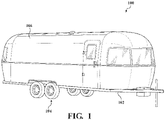
- Fig. 1 illustrates a recreational vehicle 100 comprising a chassis 102, at least one axle assembly 104 and a vehicle body 106.
- the recreational vehicle 100 is a trailer-type vehicle.
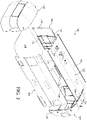
- Fig. 2 provides an exploded view of the body 106 along with a floor 108.
- the floor may or may not be considered part of the body, but is treated separately in this disclosure.
- the body has a pair of walls 110 and 112 forming the opposed sides of the body.
- the walls are generally similar in construction, though differ in the placement of doors, windows, and other details.
- wall 110 will be described in detail with the understanding that similar considerations apply to wall 112.
- the wall 110 has a bottom 114, a top 116, a front end 118 and a rear end 120.
- a roof 122 has a pair of opposed edges 124 and 126 and a front end 128 and rear end 130.
- the roof spans between the tops of the walls 110 and 112.
- a front end shell 132 is disposed at the front ends of the walls and roof and a rear end shell 134 is disposed at the rear ends of the walls and roof.
- the walls 110 and 112, roof 122 and shells 132 and 134 cooperate to enclose an interior area of the recreational vehicle.
- the floor 108 is interconnected with and extends between the bottoms of the walls 110 and 112, and the entire assembly is supported by the chassis.
- the walls 110 and 112 and the roof 122 have the same length so that their front and back ends form a generally flat surface for mounting the end shells 132 and 134
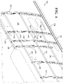
- the wall 110 has a plurality of horizontal members 140, 142, and 144 that each extend at least part way between the front end 118 and the rear end 120 of the wall 110.
- the wall may have more or fewer horizontal members and their length may vary.
- the horizontal member 142 is a middle horizontal member positioned midway between the top 116 and bottom 114 of the wall 110.
- the middle horizontal member 142 is disposed generally horizontally and extends from the rear end 120 of the wall towards to the front end 118 but terminates short of the front end of the wall. This is due to the wall 110 having a door opening 146 provided therein.
- the wall may be assembled in a different orientation than its final orientation, such as with the horizontal and vertical members both being supported on an assembly surface.
- the horizontal member 140 is positioned above the middle horizontal member 142 and may be considered an upper horizontal member. In this example, it is midway between the middle horizontal member 142 and the top 116 of the wall.
- the upper horizontal member 140 also extends generally horizontally and is therefore parallel to the middle horizontal member 142. In this example, the upper horizontal member 140 is shorter than the middle horizontal member 142, so as not to interfere with window openings such as shown at 148.
- the horizontal member 144 is positioned below the middle horizontal member 142 and may be considered a lower horizontal member. In this example, it is midway between the middle horizontal member 142 and the bottom 114 of the wall 110.
- the lower horizontal member 144 also extends generally horizontally and therefore is parallel to the middle and upper horizontal members 142 and 140. In this example, a forward end of the lower horizontal member 144 is in the same longitudinal position as a forward end of the middle horizontal member 142, adjacent the door opening 146.
- a rearward end of the lower horizontal member 144 stops short of the rear end 120 of the wall 110 to avoid interfering with an opening 150 in the wall.
- the wall 110 further has a plurality of spaced apart vertical bows 152, 154, 156, 158, 160, 162, 164, and 166.
- the wall may have more or fewer vertical bows and their height may vary.
- vertical bows 152, 154, 156 and 164 are full-height bows that extend from the bottom 114 to the top 116 of the wall 110 and the bows 158, 160, 162 and 166 are partial-height bows.
- Bows 158 and 166 extend from the bottom 114 part way to the top 116 and bows 160 and 162 extend from the top 116 part way to the bottom 114.
- the partial-height of some bows is to avoid interfering with openings or other features, such as wheel wells and windows.
- the horizontal members and the vertical bows are interconnected with one another, as will be described herein, to generally provide a grid.
- An outer wall skin 170 is attached to outer surfaces of the bows and/or horizontal members to form the wall 110.
- Figs. 4 and 5 provide more detailed views of portions of the wall 110, illustrating some of the vertical bows and horizontal members.
- Fig. 4 provides a perspective view looking rearwardly and showing more detail than in Fig. 3 .
- Fig. 5 provides a perspective view looking forwardly and also showing more detail.
- Fig. 6 provides a perspective view of one full-height vertical bow. While the vertical bows and horizontal members may take a variety of forms, Figs. 4-6 will be used to describe one exemplary design for the bows and members.
- Bows 154 and 156 are full-height bows, which extend from the bottom 114 to the top 116 of the wall 110. The bow in Fig. 6 represents bow 154. Bow 154 will be described in more detail with reference to Figs.
- the vertical bow 154 has a convex curved outer surface 180 and a concave curved inner surface 182, with the outer wall skin 170 being disposed on the outer surface 180.
- each of the vertical bows is stamped from metal, resulting in a generally C-shaped cross section.
- the "top” of the C forms an outer flange defining the outer surface 180 and the "bottom” of the C forms an inner flange defining the inner surface 182.
- the web 184 of the C extends between the inner and outer flanges.
- the web 184 may have openings defined therein, such as opening 186, for material reduction and/or providing for passage of wiring and other elements of the recreational vehicle.
- the horizontal members such as member 140 and 142, are rectangular or square tubing, which may be a non-custom item.
- the tubing is typically metal.
- the vertical bows have recesses defined therein for receiving the horizontal members.
- vertical bow 154 has an upper recess 188 for receiving the upper horizontal member 140, a middle recess 190 for receiving the middle horizontal member 142, and a lower recess 192 for receiving the lower horizontal member 144.
- the recesses are formed in the inner and outer surfaces 180 and 182 and are configured such that when the respective horizontal member is received therein, the horizontal member does not extend beyond the respective inner or outer surface adjacent the recess.
- the recesses may also be referred to more generally as receiving areas.
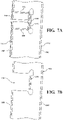
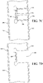
- Figs. 7A and 7B provide detailed cross-sectional views of a portion of bow 154 with the middle recess 190.
- Fig. 7A shows the recess 190 with the horizontal member 142 received therein and
- Fig. 7B shows the recess 190 without the horizontal member.
- the recess 190 is an outer recess defined in the outer surface 180 of the vertical bow 154.
- the recess 190 has a flange 191 at the back of the recess, farthest from the outer surface.
- the flange 191 is shown in cross section disposed against the back surface of the horizontal member 142.
- the vertical bow 154 is interconnected with the horizontal member 142 by a fastener, such as rivet 194, extending through the flange 191 and horizontal member.
- a fastener such as rivet 194
- the recess 190 is configured such that when the horizontal member 142 is disposed therein, an outer surface 143 of the horizontal member is generally flush with the portions of the outer surface 180 of the vertical bow 154 immediately adjacent the recess 190.
- the term "generally flush" is intended to mean that the surfaces are close enough to flush to provide a surface that is smooth enough for attachment of the outer wall skin 170 without causing uneven loading or cosmetic problems.
- the outer wall skin 170 is disposed against the outer surface 180 of the vertical bow 154 and also against the outer surface 143 of the horizontal member 142, and is attached thereto with the same fastener or rivet 194 that interconnects the bow 154 and horizontal member 142.
- a strip of high bond adhesive tape may be provided between the outer wall skin 170 and the outer surface 180, to provide a thermal conduction barrier and a rivet seal layer.
- the lower recess 192 in the vertical bow 154 in this example is an outer recess constructed in the same way as the middle recess 190.
- Figs. 7C and 7D provide detailed cross-sectional views of a portion of bow 154 with the upper recess 188.
- Fig. 7C shows the recess 188 with the horizontal member 140 received therein and
- Fig. 7D shows the recess 188 without the horizontal member.
- the recess 188 is an inner recess defined in the inner surface 182 of the vertical bow 154.
- the recess 188 has a flange 189 at the back of the recess, farthest from the inner surface 182.
- the flange 189 is shown in cross section disposed against the back surface of the horizontal member 140.
- the vertical bow 154 is interconnected with the horizontal member 140 by a fastener, such as rivet 196, extending through the flange 189 and horizontal member.
- a fastener such as rivet 196
- the recess 188 is configured such that when the horizontal member 140 is disposed therein, a surface 141 of the horizontal member is generally flush with the portions of the inner surface 182 of the vertical bow 154 immediately adjacent the recess 188.
- an inner wall skin may be disposed against the inner surfaces and interconnected therewith.
- each recess 188-192 extends only part way from one of the surfaces to the other of the surfaces of the bow, thereby leaving space between the respective horizontal member and the other side of the wall. This allows for the vertical passage of wires and other elements without the need for cutting holes and providing grommets, etc. While the wall 110 is illustrated as having two outer recesses and one inner recess, it is possible to provide a different combination as well as more or fewer recesses and horizontal members.
- the horizontal members may provide a fixture-function in the assembly of a wall for a recreational vehicle.
- hole 197 is shown in horizontal member 140, aligned with vertical bow 154. This hole 197 is to receive the rivet 196 for joining the horizontal member 140 to the vertical bow 154.
- Additional holes 198, 200, and 202 are shown spaced apart in horizontal member 140.
- a first and a second horizontal member, such as members 140 and 142 are provided and a plurality of spaced apart holes, such as holes 197-202, are formed in these members, with the hole spacing being a predefined bow spacing. That is, these holes are used to determine the position of vertical bows attached thereto.
- This bow spacing may include some holes that are spaced farther apart, such as holes 197 and 198, and some holes that are spaced more closely together, such as holes 198 and 200. Holes are formed in each of the horizontal members and are spaced apart by the same bow spacing in each one.
- the horizontal members are disposed in the recesses, the holes are aligned with the bows to position the bows and members, and then the outer wall skin is positioned against the horizontal members and the predefined holes are used to guide a drill for cutting holes in the skin. Then, a single fastener may attach the vertical bow to the horizontal member and the skin thereto. Alternatively, one fastener may be used to interconnect the bow and horizontal member and a different fastener used to attach the outer wall skin.
- the outer wall skin may be attached at additional locations to the vertical bows and horizontal members, and additional preformed holes may be provided. These additional holes are not considered as defining the bow spacing.
- a bottom horizontal member 210 is shown in cross-section.
- the same bottom horizontal member is shown in Fig. 4 at the bottom 114 of the wall.
- the bottom horizontal member may be considered part of the wall or a separate structure.
- the bottom horizontal member 210 has an upper channel 212, for receiving a lower end 214 of at least some of the vertical bows, and a floor receiving channel 216 for receiving a side edge of a floor 218.
- the floor 218 is disposed in and extends between the floor receiving channels 216 of the bottom horizontal members 210 at the bottom of the opposed walls.
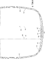
- Fig. 9 shows a pair of vertical bows 220 and 222 and a roof bow 224 extending therebetween. These bows may form part of the rear end shell 134, as shown in Fig. 2 , though other of the bows are constructed similarly.
- the roof bows 224 may be spaced apart and support an outer roof skin 226. At least some of the roof bows are longitudinally aligned with some of the vertical wall bows.
- the roof bows 224 have an upper surface 228 and an inner surface 230. As shown, some embodiments of the present disclosure provide a recreational vehicle with a generally curved inner and outer profile.
- the roof bows 224 have a central portion 232 wherein the inner surface 230 and/or outer surface 228 is flat, as shown, to allow for easier mounting of external equipment such as air conditioning units.
- the bows may have curved outer portions, outboard of the central portion.
- An inner wall skin 234 may be provided on the inner surfaces of the bows, and may be continuous or in multiple sections.
- a central inner roof panel 236 is attached to the flat central portion 232 of the roof bows 224.
- Floor-to-ceiling interior components such as walls and furniture, may be provided in the recreational vehicle, as represented by the dashed lines 238 and 240. These interior components may have inner edges 239 and 241, respectively, which are disposed outboard of the flat central inner roof panel 236, thereby allowing removal of the panel 236 without removal of the interior components.
- the outer roof skin may likewise have a central panel.
- the flat central portion of the inner surface has a different width than the flat central portion of the outer surface.
- Fig. 10 provides a detailed view of the area indicated at 10 in Fig. 9 .
- the upper end 242 of the wall bow 220 may be interconnected with an outer end 244 of the roof bow 224 by a flange 246 extending from the upper 242 of the bow 220, which is fastened to the outer end 244 of the roof bow 224.
- This approach may be used for the bows at the front end and rear end shells.
- Fig. 11 shows an approach for interconnecting the remaining wall and roof bows for some embodiments.
- a top horizontal member 250 is shown in cross-section in Fig. 11 and at the top 116 of the wall 110 in Fig. 4 .
- the top horizontal member may be I beam or H beam shaped with a lower channel 252 that receives upper ends 254 of the vertical wall bows and an upper channel 256 that received the outer ends 258 of the roof bows, which may be longitudinally aligned with the wall bows.
- the bows are interconnected with the horizontal top member.
- the outer wall skin may also be attached here, as well as a drip edge 260.
Applications Claiming Priority (1)
| Application Number | Priority Date | Filing Date | Title |
|---|---|---|---|
| US17/039,179 US11400852B2 (en) | 2020-09-30 | 2020-09-30 | RV shell and method of manufacture |
Publications (1)
| Publication Number | Publication Date |
|---|---|
| EP3978337A1 true EP3978337A1 (fr) | 2022-04-06 |
Family
ID=77750129
Family Applications (1)
| Application Number | Title | Priority Date | Filing Date |
|---|---|---|---|
| EP21196533.0A Pending EP3978337A1 (fr) | 2020-09-30 | 2021-09-14 | Coque rv et procédé de fabrication |
Country Status (4)
| Country | Link |
|---|---|
| US (1) | US11400852B2 (fr) |
| EP (1) | EP3978337A1 (fr) |
| CN (1) | CN114313028A (fr) |
| CA (1) | CA3132659A1 (fr) |
Families Citing this family (1)
| Publication number | Priority date | Publication date | Assignee | Title |
|---|---|---|---|---|
| US11820209B1 (en) * | 2022-10-07 | 2023-11-21 | H.B. Fuller Company | Watertight structures and methods of making the same |
Citations (4)
| Publication number | Priority date | Publication date | Assignee | Title |
|---|---|---|---|---|
| US4059303A (en) * | 1976-02-24 | 1977-11-22 | Ambrogio Mauri | Light alloy body structure, particularly for transport vehicles, and a process for its formation |
| CN202358193U (zh) * | 2011-11-15 | 2012-08-01 | 东莞三新电动汽车技术有限公司 | 轻量化巴士车架 |
| DE202018005759U1 (de) * | 2018-12-14 | 2019-01-21 | CellTech Metals, lnc. | Frachttransportsystem mit einem Sandwich-Paneel und einem Kanal |
| US10507875B1 (en) * | 2018-12-21 | 2019-12-17 | Celltech Metals Inc. | Trailer wall including logistics post |
Family Cites Families (5)
| Publication number | Priority date | Publication date | Assignee | Title |
|---|---|---|---|---|
| FR2762277B1 (fr) * | 1997-04-17 | 1999-07-09 | Gec Alsthom Transport Sa | Element de structure portante, structure portante, troncon de structure de caisse et caisse de vehicule comportant de telles structures |
| US6464288B2 (en) * | 2001-01-25 | 2002-10-15 | Mack Trucks, Inc. | Modular truck sleeper assembly |
| US8056958B2 (en) * | 2009-07-17 | 2011-11-15 | Navistar Canada, Inc. | School bus rollover protection structure |
| GB2534730A (en) * | 2013-09-11 | 2016-08-03 | Paradise Motor Homes Pty Ltd | Transportable body |
| CN106627330A (zh) * | 2015-10-30 | 2017-05-10 | 王龙 | 一种可拆装的房车外壳 |
-
2020
- 2020-09-30 US US17/039,179 patent/US11400852B2/en active Active
-
2021
- 2021-09-14 EP EP21196533.0A patent/EP3978337A1/fr active Pending
- 2021-09-28 CN CN202111146235.8A patent/CN114313028A/zh active Pending
- 2021-09-30 CA CA3132659A patent/CA3132659A1/fr active Pending
Patent Citations (4)
| Publication number | Priority date | Publication date | Assignee | Title |
|---|---|---|---|---|
| US4059303A (en) * | 1976-02-24 | 1977-11-22 | Ambrogio Mauri | Light alloy body structure, particularly for transport vehicles, and a process for its formation |
| CN202358193U (zh) * | 2011-11-15 | 2012-08-01 | 东莞三新电动汽车技术有限公司 | 轻量化巴士车架 |
| DE202018005759U1 (de) * | 2018-12-14 | 2019-01-21 | CellTech Metals, lnc. | Frachttransportsystem mit einem Sandwich-Paneel und einem Kanal |
| US10507875B1 (en) * | 2018-12-21 | 2019-12-17 | Celltech Metals Inc. | Trailer wall including logistics post |
Also Published As
| Publication number | Publication date |
|---|---|
| US20220097592A1 (en) | 2022-03-31 |
| US11400852B2 (en) | 2022-08-02 |
| CN114313028A (zh) | 2022-04-12 |
| CA3132659A1 (fr) | 2022-03-30 |
Similar Documents
| Publication | Publication Date | Title |
|---|---|---|
| US10118648B2 (en) | Motor vehicle rear | |
| US20010028179A1 (en) | Body structure | |
| KR100490514B1 (ko) | 자동차의 짐칸 | |
| CA2296774C (fr) | Carrosserie pour vehicule automobile | |
| CA2638205C (fr) | Caisse de camion avec cadre structurel d'entreposage externe | |
| JP4144385B2 (ja) | 自動車の車室前部の結合構造 | |
| US8272682B2 (en) | Chassis of a vehicle provided with an extruded central pillar | |
| JP6956141B2 (ja) | 車体側部構造 | |
| US20210086702A1 (en) | Modular utility insert for a vehicle | |
| EP3978337A1 (fr) | Coque rv et procédé de fabrication | |
| JP7048632B2 (ja) | キャビンモジュール及びそれを搭載した自動車 | |
| US10150517B2 (en) | Vehicle roof structure corner connector | |
| US5378094A (en) | Cargo tie-down arrangement for pick-up trucks | |
| US11180198B2 (en) | Vehicle structural assembly | |
| CN113492914A (zh) | 车辆支撑结构总成和组装方法 | |
| US11014617B2 (en) | Vehicle bed side wall configured for vertical load support | |
| JP4062235B2 (ja) | 自動車のルーフ構造 | |
| US11623690B2 (en) | Cross members on rear rails in a unibody truck | |
| EP3393891B1 (fr) | Cabine modulaire pour véhicule industriel comprenant un cadre auxiliaire, un cadre auxiliaire pour une telle cabine modulaire, et procédé de fabrication d'une telle cabine modulaire. | |
| CN113968290A (zh) | 皮卡车侧壁结构总成和结构支撑方法 | |
| DE102006015405A1 (de) | Hohlprofil für einen Dachrahmen bzw. einer Säule einer Kraftwagenkarosserie | |
| JP4271135B2 (ja) | 自動車の後部車体構造 | |
| CN108202759B (zh) | 车辆车架 | |
| US9505439B2 (en) | Variable width platform vehicle body structure and method | |
| JP4428811B2 (ja) | センタピラーの結合構造 |
Legal Events
| Date | Code | Title | Description |
|---|---|---|---|
| PUAI | Public reference made under article 153(3) epc to a published international application that has entered the european phase |
Free format text: ORIGINAL CODE: 0009012 |
|
| STAA | Information on the status of an ep patent application or granted ep patent |
Free format text: STATUS: THE APPLICATION HAS BEEN PUBLISHED |
|
| AK | Designated contracting states |
Kind code of ref document: A1 Designated state(s): AL AT BE BG CH CY CZ DE DK EE ES FI FR GB GR HR HU IE IS IT LI LT LU LV MC MK MT NL NO PL PT RO RS SE SI SK SM TR |
|
| STAA | Information on the status of an ep patent application or granted ep patent |
Free format text: STATUS: REQUEST FOR EXAMINATION WAS MADE |
|
| 17P | Request for examination filed |
Effective date: 20221006 |
|
| RBV | Designated contracting states (corrected) |
Designated state(s): AL AT BE BG CH CY CZ DE DK EE ES FI FR GB GR HR HU IE IS IT LI LT LU LV MC MK MT NL NO PL PT RO RS SE SI SK SM TR |
|
| GRAP | Despatch of communication of intention to grant a patent |
Free format text: ORIGINAL CODE: EPIDOSNIGR1 |
|
| STAA | Information on the status of an ep patent application or granted ep patent |
Free format text: STATUS: GRANT OF PATENT IS INTENDED |
|
| INTG | Intention to grant announced |
Effective date: 20240315 |