EP3978286A1 - Hybrides elektrofahrzeug - Google Patents
Hybrides elektrofahrzeug Download PDFInfo
- Publication number
- EP3978286A1 EP3978286A1 EP19930179.7A EP19930179A EP3978286A1 EP 3978286 A1 EP3978286 A1 EP 3978286A1 EP 19930179 A EP19930179 A EP 19930179A EP 3978286 A1 EP3978286 A1 EP 3978286A1
- Authority
- EP
- European Patent Office
- Prior art keywords
- generator
- inverter
- housing
- opening
- harness
- Prior art date
- Legal status (The legal status is an assumption and is not a legal conclusion. Google has not performed a legal analysis and makes no representation as to the accuracy of the status listed.)
- Granted
Links
Images


Classifications
-
- B—PERFORMING OPERATIONS; TRANSPORTING
- B60—VEHICLES IN GENERAL
- B60K—ARRANGEMENT OR MOUNTING OF PROPULSION UNITS OR OF TRANSMISSIONS IN VEHICLES; ARRANGEMENT OR MOUNTING OF PLURAL DIVERSE PRIME-MOVERS IN VEHICLES; AUXILIARY DRIVES FOR VEHICLES; INSTRUMENTATION OR DASHBOARDS FOR VEHICLES; ARRANGEMENTS IN CONNECTION WITH COOLING, AIR INTAKE, GAS EXHAUST OR FUEL SUPPLY OF PROPULSION UNITS IN VEHICLES
- B60K6/00—Arrangement or mounting of plural diverse prime-movers for mutual or common propulsion, e.g. hybrid propulsion systems comprising electric motors and internal combustion engines
- B60K6/20—Arrangement or mounting of plural diverse prime-movers for mutual or common propulsion, e.g. hybrid propulsion systems comprising electric motors and internal combustion engines the prime-movers consisting of electric motors and internal combustion engines, e.g. HEVs
- B60K6/22—Arrangement or mounting of plural diverse prime-movers for mutual or common propulsion, e.g. hybrid propulsion systems comprising electric motors and internal combustion engines the prime-movers consisting of electric motors and internal combustion engines, e.g. HEVs characterised by apparatus, components or means specially adapted for HEVs
- B60K6/40—Arrangement or mounting of plural diverse prime-movers for mutual or common propulsion, e.g. hybrid propulsion systems comprising electric motors and internal combustion engines the prime-movers consisting of electric motors and internal combustion engines, e.g. HEVs characterised by apparatus, components or means specially adapted for HEVs characterised by the assembly or relative disposition of components
- B60K6/405—Housings
-
- B—PERFORMING OPERATIONS; TRANSPORTING
- B60—VEHICLES IN GENERAL
- B60L—PROPULSION OF ELECTRICALLY-PROPELLED VEHICLES; SUPPLYING ELECTRIC POWER FOR AUXILIARY EQUIPMENT OF ELECTRICALLY-PROPELLED VEHICLES; ELECTRODYNAMIC BRAKE SYSTEMS FOR VEHICLES IN GENERAL; MAGNETIC SUSPENSION OR LEVITATION FOR VEHICLES; MONITORING OPERATING VARIABLES OF ELECTRICALLY-PROPELLED VEHICLES; ELECTRIC SAFETY DEVICES FOR ELECTRICALLY-PROPELLED VEHICLES
- B60L53/00—Methods of charging batteries, specially adapted for electric vehicles; Charging stations or on-board charging equipment therefor; Exchange of energy storage elements in electric vehicles
- B60L53/20—Methods of charging batteries, specially adapted for electric vehicles; Charging stations or on-board charging equipment therefor; Exchange of energy storage elements in electric vehicles characterised by converters located in the vehicle
- B60L53/22—Constructional details or arrangements of charging converters specially adapted for charging electric vehicles
-
- B—PERFORMING OPERATIONS; TRANSPORTING
- B60—VEHICLES IN GENERAL
- B60K—ARRANGEMENT OR MOUNTING OF PROPULSION UNITS OR OF TRANSMISSIONS IN VEHICLES; ARRANGEMENT OR MOUNTING OF PLURAL DIVERSE PRIME-MOVERS IN VEHICLES; AUXILIARY DRIVES FOR VEHICLES; INSTRUMENTATION OR DASHBOARDS FOR VEHICLES; ARRANGEMENTS IN CONNECTION WITH COOLING, AIR INTAKE, GAS EXHAUST OR FUEL SUPPLY OF PROPULSION UNITS IN VEHICLES
- B60K6/00—Arrangement or mounting of plural diverse prime-movers for mutual or common propulsion, e.g. hybrid propulsion systems comprising electric motors and internal combustion engines
- B60K6/20—Arrangement or mounting of plural diverse prime-movers for mutual or common propulsion, e.g. hybrid propulsion systems comprising electric motors and internal combustion engines the prime-movers consisting of electric motors and internal combustion engines, e.g. HEVs
- B60K6/22—Arrangement or mounting of plural diverse prime-movers for mutual or common propulsion, e.g. hybrid propulsion systems comprising electric motors and internal combustion engines the prime-movers consisting of electric motors and internal combustion engines, e.g. HEVs characterised by apparatus, components or means specially adapted for HEVs
- B60K6/40—Arrangement or mounting of plural diverse prime-movers for mutual or common propulsion, e.g. hybrid propulsion systems comprising electric motors and internal combustion engines the prime-movers consisting of electric motors and internal combustion engines, e.g. HEVs characterised by apparatus, components or means specially adapted for HEVs characterised by the assembly or relative disposition of components
-
- H—ELECTRICITY
- H02—GENERATION; CONVERSION OR DISTRIBUTION OF ELECTRIC POWER
- H02K—DYNAMO-ELECTRIC MACHINES
- H02K11/00—Structural association of dynamo-electric machines with electric components or with devices for shielding, monitoring or protection
- H02K11/30—Structural association with control circuits or drive circuits
- H02K11/33—Drive circuits, e.g. power electronics
-
- H—ELECTRICITY
- H02—GENERATION; CONVERSION OR DISTRIBUTION OF ELECTRIC POWER
- H02K—DYNAMO-ELECTRIC MACHINES
- H02K5/00—Casings; Enclosures; Supports
- H02K5/04—Casings or enclosures characterised by the shape, form or construction thereof
- H02K5/22—Auxiliary parts of casings not covered by groups H02K5/06-H02K5/20, e.g. shaped to form connection boxes or terminal boxes
- H02K5/225—Terminal boxes or connection arrangements
-
- H—ELECTRICITY
- H02—GENERATION; CONVERSION OR DISTRIBUTION OF ELECTRIC POWER
- H02K—DYNAMO-ELECTRIC MACHINES
- H02K7/00—Arrangements for handling mechanical energy structurally associated with dynamo-electric machines, e.g. structural association with mechanical driving motors or auxiliary dynamo-electric machines
- H02K7/006—Structural association of a motor or generator with the drive train of a motor vehicle
-
- B—PERFORMING OPERATIONS; TRANSPORTING
- B60—VEHICLES IN GENERAL
- B60K—ARRANGEMENT OR MOUNTING OF PROPULSION UNITS OR OF TRANSMISSIONS IN VEHICLES; ARRANGEMENT OR MOUNTING OF PLURAL DIVERSE PRIME-MOVERS IN VEHICLES; AUXILIARY DRIVES FOR VEHICLES; INSTRUMENTATION OR DASHBOARDS FOR VEHICLES; ARRANGEMENTS IN CONNECTION WITH COOLING, AIR INTAKE, GAS EXHAUST OR FUEL SUPPLY OF PROPULSION UNITS IN VEHICLES
- B60K6/00—Arrangement or mounting of plural diverse prime-movers for mutual or common propulsion, e.g. hybrid propulsion systems comprising electric motors and internal combustion engines
- B60K6/20—Arrangement or mounting of plural diverse prime-movers for mutual or common propulsion, e.g. hybrid propulsion systems comprising electric motors and internal combustion engines the prime-movers consisting of electric motors and internal combustion engines, e.g. HEVs
- B60K6/42—Arrangement or mounting of plural diverse prime-movers for mutual or common propulsion, e.g. hybrid propulsion systems comprising electric motors and internal combustion engines the prime-movers consisting of electric motors and internal combustion engines, e.g. HEVs characterised by the architecture of the hybrid electric vehicle
- B60K6/46—Series type
-
- B—PERFORMING OPERATIONS; TRANSPORTING
- B60—VEHICLES IN GENERAL
- B60L—PROPULSION OF ELECTRICALLY-PROPELLED VEHICLES; SUPPLYING ELECTRIC POWER FOR AUXILIARY EQUIPMENT OF ELECTRICALLY-PROPELLED VEHICLES; ELECTRODYNAMIC BRAKE SYSTEMS FOR VEHICLES IN GENERAL; MAGNETIC SUSPENSION OR LEVITATION FOR VEHICLES; MONITORING OPERATING VARIABLES OF ELECTRICALLY-PROPELLED VEHICLES; ELECTRIC SAFETY DEVICES FOR ELECTRICALLY-PROPELLED VEHICLES
- B60L2210/00—Converter types
- B60L2210/10—DC to DC converters
-
- Y—GENERAL TAGGING OF NEW TECHNOLOGICAL DEVELOPMENTS; GENERAL TAGGING OF CROSS-SECTIONAL TECHNOLOGIES SPANNING OVER SEVERAL SECTIONS OF THE IPC; TECHNICAL SUBJECTS COVERED BY FORMER USPC CROSS-REFERENCE ART COLLECTIONS [XRACs] AND DIGESTS
- Y02—TECHNOLOGIES OR APPLICATIONS FOR MITIGATION OR ADAPTATION AGAINST CLIMATE CHANGE
- Y02T—CLIMATE CHANGE MITIGATION TECHNOLOGIES RELATED TO TRANSPORTATION
- Y02T10/00—Road transport of goods or passengers
- Y02T10/60—Other road transportation technologies with climate change mitigation effect
- Y02T10/62—Hybrid vehicles
Definitions
- the present invention relates to a hybrid electric vehicle.
- a Patent Literature 1 listed below discloses first and second motor-generators and an inverter of a hybrid electric vehicle.
- the first and second motor-generators are arranged in close proximity to each other so that their rotation axes are parallel.
- the first motor-generator mainly generates electricity from an output of an internal combustion engine.
- the second motor-generator mainly drives drive wheels of the vehicle.
- the inverter is also located in close proximity to the generator and the motor-generator.
- the generator and the motor-generator are electrically connected with the inverter by wiring harnesses, respectively.
- Patent Literature 1 Japanese Granted Patent Publication No. 3843702
- the wiring harness connecting the first motor-generator to the inverter is thick, short, and routed straight because it is for high-voltage AC three-phase power. For this reason, vibrations of the internal combustion engine input to the first motor-generator are transmitted to the wiring harness through a rotor and bearings of the first motor-generator. Furthermore, the wiring harness, which is short and routed straight, does not flex, so that it transmits the vibrations to the inverter. Thus, since the vibrations of the internal combustion engine are transmitted to the inverter, components of the inverter are required to be resistant to the vibrations. This results in a larger size of the inverter.
- a hybrid electric vehicle includes a generator mechanically connected with an internal combustion engine, and a motor-generator mechanically connected with drive wheels.
- the generator is electrically connected with an inverter by a wiring harness.
- a generator opening thorough which one end of the wiring harness is inserted is opened on a housing of the generator.
- An inverter opening thorough which another end of the wiring harness is inserted is opened on a housing of the inverter.
- the one end of the wiring harness is led out from the inverter opening in a first direction toward the generator.
- the other end of the wiring harness is led out from the generator opening in a second direction that is different from the first direction.
- the inverter opening is set off with respect to the generator opening in the second direction, and at least a portion of the wiring harness extends between the generator housing and the inverter housing.
- the hybrid electric vehicle (HEV) 1 is equipped with an internal combustion engine (ICE) 2, a generator 3, a motor-generator (MG) 4, and an inverter 5 in an engine compartment of a front section of the vehicle.
- the generator 3 is mechanically connected with the ICE 2 with a gearbox 6 interposed therebetween.
- the MG 4 is mechanically connected with driving wheels (front wheels) 7 with the gearbox 6 interposed therebetween.
- the inverter 5 is electrically connected with both the generator 3 and the MG 4.
- the inverter 5 is also electrically connected with a high-voltage battery 8.
- the HEV 1 is also equipped with a low-voltage (12V) battery for auxiliary devices.
- the low-voltage battery is electrically connected with the high-voltage battery 8 through a DC/DC converter built in the inverter 5. The output from the DC/DC converter charges the low-voltage battery and is supplied directly to the auxiliary devices.
- the HEV 1 adopts a series hybrid system, and the output (driving force) of the ICE 2 is not transmitted to the drive wheels 7, but to the generator 3 via a speed-increasing gear set in the gearbox 6.
- the generator 3 is mechanically connected with the ICE 2.
- the electricity generated by the generator 3 is supplied to the MG 4 or (and) the high-voltage battery 8 via the inverter 5.
- the electricity stored in the high-voltage battery 8 can be also supplied to the MG 4.
- the ICE 2 in the present embodiment does not drive the HEV 1 with its output, but is used only for generating electricity. Therefore, the ICE 2 functions as part of the power generation system.
- the output (driving force) of the MG 4 is transmitted to the drive wheels 7 through a reduction gear set in the gearbox 6 and drive shafts.
- MG 4 is mechanically connected with the drive wheels 7.
- the electricity regenerated by the MG 4 during deceleration of the HEV 1 can be also supplied to the high-voltage battery 8 via the inverter 5.
- the gearbox 6 houses the speed-increasing gear set and the reduction gear set, but there is no gear meshing between them.
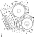
- FIG. 2 shows the generator 3 and inverter 5 as seen from the front of the vehicle.
- Fig. 2 also shows the gearbox 6, and P1 in the figure is a fastening plane between the ICE 2 and the gearbox 6 and P2 in the figure is a fastening plane between the gearbox 6 and the generator 3.
- the fastening surface P2 is also a fastening plane between the gearbox 6 and the MG 4.
- the MG 4 is located at the back of the generator 3 (in Fig. 2 ).
- Fig. 3 is a cross-sectional view taken along a line III-III shown in Fig. 2 .
- the inverter 5 is located above the generator 3 and the MG 4, in close proximity to them.
- a housing 3H of the generator 3 (a generator housing) is made of aluminum alloy and comprised of a cylindrical main body 3C and an end cap 3B that has a shape formed by integrating a cylinder and a box together.
- the main body 3C and the end cap 3B are rigidly attached to each other by bolts.
- the main body 3C is also rigidly attached to the gearbox 6 by bolts.
- a stator and a rotor of the generator 3 are built in the generator housing 3H.
- the generator housing 3H rotatably holds a rotary shaft 3S of the rotor via bearings. One end of the rotary shaft 3S extends into the inside of the gearbox 6, and the rotor is rotated by the above-mentioned speed-increasing gear set.
- the generator housing 3H basically has a cylindrical shape, but its left-side portion (on the right side in Fig. 2 seen from the front of the HEV 1: on the opposite side to the gearbox 6) has a shape such that a cube is protruded from the cylinder to form a terminal box 3T.
- the terminal box 3T is protruded toward the inverter 5. Therefore, a space is formed between a right-side portion (on a left side in Fig. 2 ) of the generator 3 and the inverter 5.
- Terminals three connected to stator coils are arranged in the terminal box 3T. Inside the terminal box 3T, terminals on one end of the harness 9 are electrically connected to terminals of the generator 3.
- a generator opening 3O is opened for leading the one end of the harness 9 out of the generator housing 3H.
- the one end of the harness 9 is inserted through the generator opening 3O. Since the generator 3 is a high-voltage three-phase AC generator, the harness 9 is a bundle of plural thick electric wires.
- a housing 4H of the MG 4 (an MG housing) is also made of aluminum alloy and has a cylindrical shape. But a flange is formed on at an end of its right-side portion (on the left side in Fig. 2 ) of the MG housing 4H for being fastened with the gearbox 6.
- the MG housing 4H is rigidly connected to the gearbox 6 by bolts at this flange.
- a portion (a lower housing 5L) of an after-explained housing 5H of the inverter 5 (an inverter housing) is monolithically formed at this flange.
- a stator and a rotor of the MG 4 are built inside the MG housing 4H.
- the MG housing 4H holds a rotary shaft of the rotor rotatably via bearings. One end of the rotary shaft is extended into the gearbox 6 to rotate drive shafts through the above-mentioned speed-increasing gear set.
- An inverter housing 5H is also made of aluminum alloy and has a box shape.
- the inverter housing 5H is comprised of an upper housing 5U and a lower housing 5L.
- the upper housing 5U and the lower housing 5L are rigidly connected to each other by bolts.
- the inverter housing 5H is rigidly fixed with the MG housing 4H.
- electronic components such as a power module 5G for the generator 3 (a generator power module), a power module 5M for the MG 4 (an MG power module) and a smoothing capacitor 5C are stored.
- the generator power module 5G is electrically connected with the generator 3 via the harness 9.
- the MG power module 5M is also electrically connected to the MG 4. Both the generator power module 5G and the MG power module 5M are electrically connected to the smoothing capacitor 5C.
- the smoothing capacitor 5C is located closer to the MG 4 than the generator power module 5G and the MG power module 5M. More specifically, the smoothing capacitor 5C is fixed on an inner bottom surface of the inverter housing 5H.
- the generator power module 5G and the MG power module 5M are arranged side by side on an opposite side to the smoothing capacitor 5C with respect to the MG 4. More specifically, the generator power module 5G and the MG power module 5M are fixed on an inner top surface of the inverter housing 5H. Since the smoothing capacitor 5C is used by both the generator power module 5G and the MG power module 5M, it is placed in the center between the two in consideration of their wiring lengths.
- a portion of the inverter housing 5H closest to the gearbox 6 (i.e. the ICE 2) and farthest from the MG 4 is protruded outward (upward), and an inverter opening 5O is opened in this protruded part for leading the other end of the harness 9 out of the inverter housing 5H. That is, the other end of the harness 9 is inserted through the inverter opening 5O.
- the inverter opening 5O is located at a position on the outer surface of the inverter housing 5H that is closest to the ICE 2 and that is on a furthest side of the inverter housing 5H from the MG 4.
- the right-side portion (on the left side in Fig. 2 ) of the generator housing 3H is fixed to the MG housing 4H (the lower housing 5L) by a first bracket 10, and the left-side portion (on the left side in Fig. 2 ) thereof is fixed to the MG housing 4H by a second bracket 11.
- the first bracket 10 and the second bracket 11 are made of steel, which is more flexible as metal than aluminum alloy, and are plate materials that can flex slightly. (Vibration durability and damping characteristics of aluminum-based metal [aluminum alloy] is inferior to those of iron-based metal [steel].) Therefore, the first bracket 10 and the second bracket 11 damp vibrations of the generator 3 and thereby hardly transmit them to the MG 4.
- a lead-out direction of its one end from the inverter opening 5O is defined as a first direction D1 (see Fig. 2 and Fig. 3 ) and a lead-out direction of its other end from the generator opening 3O is defined as a second direction D2 (see Fig. 2 ).
- the first direction D1 is the direction directing from the inverter opening 5O toward the generator 3.
- the second direction D2 is parallel to an axial direction DS (see Fig. 2 ) of the rotary shaft 3S of the generator 3 in the present embodiment. In other words, the first direction D1 and the second direction D2 are different from each other.
- the first direction D1 and the second direction D2 are perpendicular to each other. Therefore, the harness 9 extending between the inverter opening 5O and the generator opening 3O is necessarily curved and does not extend straight. Since the curved portion of the harness 9 can flex, it becomes possible to deter transmission of vibrations from the generator 3 to the inverter 5 (to absorb the vibrations).
- the inverter opening 5O is set off with respect to the generator opening 3O opened on the terminal box 3T in the second direction D2.
- the position of the inverter opening 5O is different from the position of the generator opening 3O along the second direction D2. That is, the inverter opening 5O and the generator opening 3O are not on the same plane. Therefore, the harness 9 can be made longer, and the transmission of vibrations from the generator 3 to the inverter 5 can be deterred more effectively.
- the curvature radius of the harness 9 can be made large.
- at least a portion of the harness 9 extends through a space between the generator 3 and the inverter 5. Therefore, it is preferable even when the harness 9 is long, because this space can be used effectively. By effectively utilizing this space, the height of the hybrid system unit can be reduced and thereby it can be downsized.
- the harness 9 inevitably curves.
- the above-mentioned vibrations can be absorbed.
- the first direction D1 toward the generator 3 and the protruding direction of the terminal box 3T, on which the generator opening 3O is formed, toward the inverter 5 it is preferable in view of smooth routing of the curved harness 9 that the second direction D2 is parallel to the axial direction DS.
- the harness 9 is made long due to the offset of the inverter opening 5O with respect to the generator opening 3O in the second direction D2, it is preferable because the space between the generator 3 and the inverter 5 can be effectively utilized.
- the inverter opening 5O is opened on the inverter housing 5H at its outward (upward) protruding portion furthest from the MG 4.
- This allows the harness 9 to be made longer and the curvature radius of the flexure of the harness 9 can be made large. Since the harness 9 is thick as explained above and thereby is difficult to be flexed, its large curvature radius facilitates the routing of the harness 9. Further, its large curvature radius does not put excessive stresses on the harness 9.
- the above-mentioned routing of the harness 9 relates to the positional relationship viewed from the front of the vehicle. Further in the present embodiment, as shown in Fig. 3 , the harness 9 is routed such that the smoothing capacitor 5C does not overlap with the harness 9 when viewed from the axial direction DS. Since the smoothing capacitor 5C does not overlap with the harness 9, the inverter opening 5O and the generator opening 3O are arranged in close proximity along the first direction D1 when viewed from the axial direction DS, that is, the inverter housing 5H and the generator housing 3H (the terminal box 3T) can be arranged in close proximity.
- the bottom of the inverter housing 5H is deformed to avoid the terminal box 3T, and this configuration can be brought precisely because the both don't overlap with each other.
- This configuration allows the height of the hybrid system unit to be reduced, and thereby the system can be downsized. Note that, even if the inverter housing 5H and the generator housing 3H (the terminal box 3T) are placed in close proximity, the harness 9 is also routed in the second direction D2, and thereby the harness 9 can be made long by being curved to deter the transmission of the vibrations.
- the HEV 1 in this embodiment adopts a series hybrid system. Therefore, the vibrations of the ICE 2 is transmitted to the rotary shaft 3S of the generator 3, which is mechanically connected to the ICE 2. The vibrations are also transmitted to the generator housing 3H and the stator in its inside through the bearings. Further, the vibrations are also transmitted to the harness 9 via the stator coils, but they are absorbed by the harness 9 as explained above.
- the generator housing 3H is not rigidly connected to the MG housing 4H, so that the above-mentioned vibrations are not directly transmitted to the MG housing 4H. Therefore, the transmission of the vibrations of the ICE 2 to the inverter 5 can be suitably suppressed. As a result, the components of the inverter 5 are not required to have excessive vibration resistance.
- the first direction D1 toward the generator (the lead-out direction of the harness 9 from the inverter opening 5O) is different from the second direction D2 (the lead-out direction of the harness 9 from the generator opening 3O). Therefore, the harness 9 necessarily curves.
- the inverter opening 5O is set off with respect to the generator opening 3O in the second direction D2. Therefore, the harness 9 can be made longer.
- the harness 9 can absorb the vibrations of the ICE 2 and deter the transmission of the vibrations of the ICE 2 to the inverter 5.
- at least the portion of the harness 9 extends between the generator housing 3H and the inverter housing 5H. Therefore, even if the harness 9 is long, the space between the generator housing 3H and the inverter housing 5H can be utilized effectively, and thereby the height of the hybrid system unit can be reduced to make it downsized.
- the second direction D2 is parallel to the axial direction DS of the rotary shaft 3S of the generator 3, and the generator opening 3O is opened on the terminal box 3T protruding toward the inverter 5.
- the above-mentioned space between the generator housing 3H and the inverter housing 5H can be formed beside the terminal box 3T, and the harness 9 can be smoothly led out from the generator housing 3H to the space in the axial direction DS. Therefore, the harness 9 can be smoothly routed.
- the first direction D1 is the direction extending toward the generator 3, and thereby it intersects the second direction D2 (the axial direction DS).
- the harness 9 can smoothly flex from the first direction D1 to the second direction D2.
- the inverter opening 5O is opened at a position on the outer surface of the inverter housing 5H that is closest to the ICE 2, and the terminal box 3T is located at a positon on the generator housing 3H that is on the farthest side from the inverter opening 5O along the axial direction DS. Therefore, the distance along the axial direction DS between the inverter opening 5O and the generator opening 3O formed in the terminal box 3T can be as long as possible. As a result, the harness 9 can be made long and it can absorb the above-mentioned vibrations effectively.
- the inverter opening 5O is located on the inverter housing 5H at a position on the farthest side from the MG 4, and thereby the harness 9 can be made long even along the first direction D1 to absorb the above-mentioned vibrations more effectively.
- the curvature radius of the flexure of the harness 9 from the first direction D1 to the second direction D2 can be made large. A large curvature radius makes it easier to route the harness 9 and does not cause excessive stress on the harness 9.
- the generator power module 5G and the MG power module 5M are arranged side by side on the opposite side to the MG 4 with respect to the smoothing capacitor 5C.
- the smoothing capacitor 5C does not overlap with the harness 9 when viewed along the axial direction DS.
- the inverter housing 5H and the generator housing 3H are arranged in close proximity along the first direction D1. Therefore, the height of the hybrid system unit can be reduced, and thereby the system can be downsized.
- the present invention is not limited to the embodiment described above.
- the inverter opening 5O is arranged on the side close to the ICE 2 and the generator opening 3O is arranged on the side far from the ICE 2 (the inverter opening 5O and the generator opening 3O are opened toward the ICE 2).
- the inverter opening may be placed on the side far from the ICE and the generator opening may be placed close to the ICE (the inverter opening and the generator opening are opened in the opposite direction to the ICE).
- the harness 9 can be necessarily curved by making the first direction D1 towards the generator 3 different from the second direction D2.
- the hybrid system may be mounted at a position other than the front section of the vehicle.
- the mounting orientation of the hybrid system is not limited to the orientation in the above embodiment.
Landscapes
- Engineering & Computer Science (AREA)
- Power Engineering (AREA)
- Transportation (AREA)
- Mechanical Engineering (AREA)
- Chemical & Material Sciences (AREA)
- Combustion & Propulsion (AREA)
- Microelectronics & Electronic Packaging (AREA)
- Hybrid Electric Vehicles (AREA)
- Motor Or Generator Frames (AREA)
- Arrangement Or Mounting Of Propulsion Units For Vehicles (AREA)
Applications Claiming Priority (1)
| Application Number | Priority Date | Filing Date | Title |
|---|---|---|---|
| PCT/JP2019/021663 WO2020240804A1 (ja) | 2019-05-31 | 2019-05-31 | ハイブリッド電気自動車 |
Publications (3)
| Publication Number | Publication Date |
|---|---|
| EP3978286A1 true EP3978286A1 (de) | 2022-04-06 |
| EP3978286A4 EP3978286A4 (de) | 2022-06-22 |
| EP3978286B1 EP3978286B1 (de) | 2024-03-06 |
Family
ID=73553726
Family Applications (1)
| Application Number | Title | Priority Date | Filing Date |
|---|---|---|---|
| EP19930179.7A Active EP3978286B1 (de) | 2019-05-31 | 2019-05-31 | Hybrides elektrofahrzeug |
Country Status (5)
| Country | Link |
|---|---|
| US (1) | US12049147B2 (de) |
| EP (1) | EP3978286B1 (de) |
| JP (1) | JP7140283B2 (de) |
| CN (1) | CN113891813B (de) |
| WO (1) | WO2020240804A1 (de) |
Families Citing this family (3)
| Publication number | Priority date | Publication date | Assignee | Title |
|---|---|---|---|---|
| EP4101672A4 (de) * | 2020-02-04 | 2023-01-18 | NISSAN MOTOR Co., Ltd. | Hybridsystem |
| JP7567829B2 (ja) * | 2022-02-18 | 2024-10-16 | トヨタ自動車株式会社 | 機電一体ユニット |
| CN117507785B (zh) * | 2022-07-29 | 2024-12-10 | 比亚迪股份有限公司 | 驱动总成和具有其的车辆 |
Family Cites Families (17)
| Publication number | Priority date | Publication date | Assignee | Title |
|---|---|---|---|---|
| FR2752778B1 (fr) * | 1996-08-27 | 1998-10-09 | Smh Management Services Ag | Groupe de traction tandem a reducteurs et vehicule a traction electrique ou hybride comportant un tel groupe |
| JP4072882B2 (ja) * | 1999-09-30 | 2008-04-09 | 富士重工業株式会社 | 車載用補機部品の取付構造 |
| JP3843702B2 (ja) | 2000-06-09 | 2006-11-08 | アイシン・エィ・ダブリュ株式会社 | 電動車両駆動用駆動装置 |
| JP3815456B2 (ja) * | 2003-04-09 | 2006-08-30 | トヨタ自動車株式会社 | ハイブリッド車両における高圧電線の配策構造 |
| CN101784407B (zh) * | 2007-08-24 | 2013-08-14 | 丰田自动车株式会社 | 车辆 |
| JP2009286287A (ja) * | 2008-05-29 | 2009-12-10 | Toyota Motor Corp | 取り付け構造 |
| JP5211081B2 (ja) * | 2009-05-22 | 2013-06-12 | 日産自動車株式会社 | 電気自動車の電気部品搭載構造 |
| JP5856410B2 (ja) * | 2011-08-31 | 2016-02-09 | トヨタ自動車株式会社 | 電気自動車用の電力変換装置および電気自動車 |
| JP2013082339A (ja) * | 2011-10-11 | 2013-05-09 | Suzuki Motor Corp | ハイブリッド車両用駆動装置 |
| JP5761009B2 (ja) * | 2011-12-27 | 2015-08-12 | トヨタ自動車株式会社 | ハイブリッド車両 |
| JP2013147045A (ja) * | 2012-01-17 | 2013-08-01 | Nissan Motor Co Ltd | ハイブリッド車両のパワートレーン系要素配置構造 |
| JP2013147046A (ja) * | 2012-01-17 | 2013-08-01 | Nissan Motor Co Ltd | ハイブリッド車両のパワートレーン系要素配置構造 |
| JP5929435B2 (ja) * | 2012-04-04 | 2016-06-08 | スズキ株式会社 | ハイブリッド車両用動力装置 |
| WO2013183500A1 (ja) | 2012-06-05 | 2013-12-12 | 日産自動車株式会社 | 電動車両の強電ハーネス接続構造 |
| JP2014097727A (ja) * | 2012-11-14 | 2014-05-29 | Suzuki Motor Corp | 車両用高電圧ケーブルの配索構造 |
| JP2015204688A (ja) * | 2014-04-14 | 2015-11-16 | トヨタ自動車株式会社 | 電動車両 |
| JP7438481B2 (ja) * | 2019-08-22 | 2024-02-27 | マツダ株式会社 | 車両前部構造 |
-
2019
- 2019-05-31 JP JP2021521716A patent/JP7140283B2/ja active Active
- 2019-05-31 US US17/614,893 patent/US12049147B2/en active Active
- 2019-05-31 WO PCT/JP2019/021663 patent/WO2020240804A1/ja not_active Ceased
- 2019-05-31 EP EP19930179.7A patent/EP3978286B1/de active Active
- 2019-05-31 CN CN201980096954.8A patent/CN113891813B/zh active Active
Also Published As
| Publication number | Publication date |
|---|---|
| JP7140283B2 (ja) | 2022-09-21 |
| JPWO2020240804A1 (de) | 2020-12-03 |
| US12049147B2 (en) | 2024-07-30 |
| CN113891813A (zh) | 2022-01-04 |
| CN113891813B (zh) | 2024-10-01 |
| EP3978286B1 (de) | 2024-03-06 |
| EP3978286A4 (de) | 2022-06-22 |
| US20220234456A1 (en) | 2022-07-28 |
| WO2020240804A1 (ja) | 2020-12-03 |
Similar Documents
| Publication | Publication Date | Title |
|---|---|---|
| US20190312492A1 (en) | Integrated unit | |
| KR20200057641A (ko) | 차량용 구동 시스템 | |
| CN101883692B (zh) | 车辆用驱动装置 | |
| EP3978286B1 (de) | Hybrides elektrofahrzeug | |
| CN107206884A (zh) | 混合动力车辆用驱动装置 | |
| US20090294626A1 (en) | Mounting structure | |
| JPWO2020240804A5 (de) | ||
| EP4470841A1 (de) | Befestigungsstruktur für einen kabelbaum | |
| JP2021044987A (ja) | 車両用駆動ユニット | |
| JP6997245B2 (ja) | 回転電機駆動ユニット | |
| JP2009142038A (ja) | 車両用駆動装置 | |
| US11772478B2 (en) | Vehicle | |
| JP2020089255A (ja) | 車両用駆動装置 | |
| US12397666B2 (en) | Electric vehicle | |
| JP2020083179A (ja) | 車両用駆動装置 | |
| US20250214408A1 (en) | Mounting structure for electrical device | |
| US20250167629A1 (en) | Drive unit | |
| US20240286482A1 (en) | Electrified vehicle | |
| US20250229622A1 (en) | Drive device for hybrid electric vehicle | |
| US20250162399A1 (en) | Electric vehicle | |
| EP4477437A1 (de) | Antriebsstrangstruktur eines fahrzeugs und fahrzeug | |
| JP7677121B2 (ja) | シリーズハイブリッド式駆動装置 | |
| US20250249737A1 (en) | Vehicle | |
| JP2026067626A (ja) | 電動車両の駆動ユニット | |
| JP2025152452A (ja) | 車両のパワートレイン構造 |
Legal Events
| Date | Code | Title | Description |
|---|---|---|---|
| STAA | Information on the status of an ep patent application or granted ep patent |
Free format text: STATUS: UNKNOWN |
|
| STAA | Information on the status of an ep patent application or granted ep patent |
Free format text: STATUS: THE INTERNATIONAL PUBLICATION HAS BEEN MADE |
|
| PUAI | Public reference made under article 153(3) epc to a published international application that has entered the european phase |
Free format text: ORIGINAL CODE: 0009012 |
|
| STAA | Information on the status of an ep patent application or granted ep patent |
Free format text: STATUS: REQUEST FOR EXAMINATION WAS MADE |
|
| 17P | Request for examination filed |
Effective date: 20211228 |
|
| AK | Designated contracting states |
Kind code of ref document: A1 Designated state(s): AL AT BE BG CH CY CZ DE DK EE ES FI FR GB GR HR HU IE IS IT LI LT LU LV MC MK MT NL NO PL PT RO RS SE SI SK SM TR |
|
| A4 | Supplementary search report drawn up and despatched |
Effective date: 20220524 |
|
| RIC1 | Information provided on ipc code assigned before grant |
Ipc: B60K 6/405 20071001ALI20220518BHEP Ipc: B60K 6/46 20071001ALI20220518BHEP Ipc: B60K 6/44 20071001ALI20220518BHEP Ipc: B60K 6/40 20071001AFI20220518BHEP |
|
| DAV | Request for validation of the european patent (deleted) | ||
| DAX | Request for extension of the european patent (deleted) | ||
| GRAP | Despatch of communication of intention to grant a patent |
Free format text: ORIGINAL CODE: EPIDOSNIGR1 |
|
| STAA | Information on the status of an ep patent application or granted ep patent |
Free format text: STATUS: GRANT OF PATENT IS INTENDED |
|
| INTG | Intention to grant announced |
Effective date: 20231221 |
|
| GRAS | Grant fee paid |
Free format text: ORIGINAL CODE: EPIDOSNIGR3 |
|
| GRAA | (expected) grant |
Free format text: ORIGINAL CODE: 0009210 |
|
| STAA | Information on the status of an ep patent application or granted ep patent |
Free format text: STATUS: THE PATENT HAS BEEN GRANTED |
|
| AK | Designated contracting states |
Kind code of ref document: B1 Designated state(s): AL AT BE BG CH CY CZ DE DK EE ES FI FR GB GR HR HU IE IS IT LI LT LU LV MC MK MT NL NO PL PT RO RS SE SI SK SM TR |
|
| REG | Reference to a national code |
Ref country code: CH Ref legal event code: EP |
|
| REG | Reference to a national code |
Ref country code: DE Ref legal event code: R096 Ref document number: 602019048041 Country of ref document: DE |
|
| REG | Reference to a national code |
Ref country code: IE Ref legal event code: FG4D |
|
| REG | Reference to a national code |
Ref country code: LT Ref legal event code: MG9D |
|
| PG25 | Lapsed in a contracting state [announced via postgrant information from national office to epo] |
Ref country code: LT Free format text: LAPSE BECAUSE OF FAILURE TO SUBMIT A TRANSLATION OF THE DESCRIPTION OR TO PAY THE FEE WITHIN THE PRESCRIBED TIME-LIMIT Effective date: 20240306 |
|
| REG | Reference to a national code |
Ref country code: NL Ref legal event code: MP Effective date: 20240306 |
|
| PG25 | Lapsed in a contracting state [announced via postgrant information from national office to epo] |
Ref country code: GR Free format text: LAPSE BECAUSE OF FAILURE TO SUBMIT A TRANSLATION OF THE DESCRIPTION OR TO PAY THE FEE WITHIN THE PRESCRIBED TIME-LIMIT Effective date: 20240607 |
|
| PG25 | Lapsed in a contracting state [announced via postgrant information from national office to epo] |
Ref country code: HR Free format text: LAPSE BECAUSE OF FAILURE TO SUBMIT A TRANSLATION OF THE DESCRIPTION OR TO PAY THE FEE WITHIN THE PRESCRIBED TIME-LIMIT Effective date: 20240306 Ref country code: RS Free format text: LAPSE BECAUSE OF FAILURE TO SUBMIT A TRANSLATION OF THE DESCRIPTION OR TO PAY THE FEE WITHIN THE PRESCRIBED TIME-LIMIT Effective date: 20240606 |
|
| PG25 | Lapsed in a contracting state [announced via postgrant information from national office to epo] |
Ref country code: ES Free format text: LAPSE BECAUSE OF FAILURE TO SUBMIT A TRANSLATION OF THE DESCRIPTION OR TO PAY THE FEE WITHIN THE PRESCRIBED TIME-LIMIT Effective date: 20240306 |
|
| PG25 | Lapsed in a contracting state [announced via postgrant information from national office to epo] |
Ref country code: RS Free format text: LAPSE BECAUSE OF FAILURE TO SUBMIT A TRANSLATION OF THE DESCRIPTION OR TO PAY THE FEE WITHIN THE PRESCRIBED TIME-LIMIT Effective date: 20240606 Ref country code: NO Free format text: LAPSE BECAUSE OF FAILURE TO SUBMIT A TRANSLATION OF THE DESCRIPTION OR TO PAY THE FEE WITHIN THE PRESCRIBED TIME-LIMIT Effective date: 20240606 Ref country code: LT Free format text: LAPSE BECAUSE OF FAILURE TO SUBMIT A TRANSLATION OF THE DESCRIPTION OR TO PAY THE FEE WITHIN THE PRESCRIBED TIME-LIMIT Effective date: 20240306 Ref country code: HR Free format text: LAPSE BECAUSE OF FAILURE TO SUBMIT A TRANSLATION OF THE DESCRIPTION OR TO PAY THE FEE WITHIN THE PRESCRIBED TIME-LIMIT Effective date: 20240306 Ref country code: GR Free format text: LAPSE BECAUSE OF FAILURE TO SUBMIT A TRANSLATION OF THE DESCRIPTION OR TO PAY THE FEE WITHIN THE PRESCRIBED TIME-LIMIT Effective date: 20240607 Ref country code: FI Free format text: LAPSE BECAUSE OF FAILURE TO SUBMIT A TRANSLATION OF THE DESCRIPTION OR TO PAY THE FEE WITHIN THE PRESCRIBED TIME-LIMIT Effective date: 20240306 Ref country code: ES Free format text: LAPSE BECAUSE OF FAILURE TO SUBMIT A TRANSLATION OF THE DESCRIPTION OR TO PAY THE FEE WITHIN THE PRESCRIBED TIME-LIMIT Effective date: 20240306 Ref country code: BG Free format text: LAPSE BECAUSE OF FAILURE TO SUBMIT A TRANSLATION OF THE DESCRIPTION OR TO PAY THE FEE WITHIN THE PRESCRIBED TIME-LIMIT Effective date: 20240306 |
|
| REG | Reference to a national code |
Ref country code: AT Ref legal event code: MK05 Ref document number: 1663163 Country of ref document: AT Kind code of ref document: T Effective date: 20240306 |
|
| PG25 | Lapsed in a contracting state [announced via postgrant information from national office to epo] |
Ref country code: SE Free format text: LAPSE BECAUSE OF FAILURE TO SUBMIT A TRANSLATION OF THE DESCRIPTION OR TO PAY THE FEE WITHIN THE PRESCRIBED TIME-LIMIT Effective date: 20240306 Ref country code: LV Free format text: LAPSE BECAUSE OF FAILURE TO SUBMIT A TRANSLATION OF THE DESCRIPTION OR TO PAY THE FEE WITHIN THE PRESCRIBED TIME-LIMIT Effective date: 20240306 |
|
| PG25 | Lapsed in a contracting state [announced via postgrant information from national office to epo] |
Ref country code: NL Free format text: LAPSE BECAUSE OF FAILURE TO SUBMIT A TRANSLATION OF THE DESCRIPTION OR TO PAY THE FEE WITHIN THE PRESCRIBED TIME-LIMIT Effective date: 20240306 |
|
| PG25 | Lapsed in a contracting state [announced via postgrant information from national office to epo] |
Ref country code: NL Free format text: LAPSE BECAUSE OF FAILURE TO SUBMIT A TRANSLATION OF THE DESCRIPTION OR TO PAY THE FEE WITHIN THE PRESCRIBED TIME-LIMIT Effective date: 20240306 |
|
| PG25 | Lapsed in a contracting state [announced via postgrant information from national office to epo] |
Ref country code: IS Free format text: LAPSE BECAUSE OF FAILURE TO SUBMIT A TRANSLATION OF THE DESCRIPTION OR TO PAY THE FEE WITHIN THE PRESCRIBED TIME-LIMIT Effective date: 20240706 |
|
| PG25 | Lapsed in a contracting state [announced via postgrant information from national office to epo] |
Ref country code: PT Free format text: LAPSE BECAUSE OF FAILURE TO SUBMIT A TRANSLATION OF THE DESCRIPTION OR TO PAY THE FEE WITHIN THE PRESCRIBED TIME-LIMIT Effective date: 20240708 Ref country code: SM Free format text: LAPSE BECAUSE OF FAILURE TO SUBMIT A TRANSLATION OF THE DESCRIPTION OR TO PAY THE FEE WITHIN THE PRESCRIBED TIME-LIMIT Effective date: 20240306 |
|
| PG25 | Lapsed in a contracting state [announced via postgrant information from national office to epo] |
Ref country code: EE Free format text: LAPSE BECAUSE OF FAILURE TO SUBMIT A TRANSLATION OF THE DESCRIPTION OR TO PAY THE FEE WITHIN THE PRESCRIBED TIME-LIMIT Effective date: 20240306 Ref country code: CZ Free format text: LAPSE BECAUSE OF FAILURE TO SUBMIT A TRANSLATION OF THE DESCRIPTION OR TO PAY THE FEE WITHIN THE PRESCRIBED TIME-LIMIT Effective date: 20240306 |
|
| PG25 | Lapsed in a contracting state [announced via postgrant information from national office to epo] |
Ref country code: AT Free format text: LAPSE BECAUSE OF FAILURE TO SUBMIT A TRANSLATION OF THE DESCRIPTION OR TO PAY THE FEE WITHIN THE PRESCRIBED TIME-LIMIT Effective date: 20240306 |
|
| PG25 | Lapsed in a contracting state [announced via postgrant information from national office to epo] |
Ref country code: PL Free format text: LAPSE BECAUSE OF FAILURE TO SUBMIT A TRANSLATION OF THE DESCRIPTION OR TO PAY THE FEE WITHIN THE PRESCRIBED TIME-LIMIT Effective date: 20240306 |
|
| PG25 | Lapsed in a contracting state [announced via postgrant information from national office to epo] |
Ref country code: SK Free format text: LAPSE BECAUSE OF FAILURE TO SUBMIT A TRANSLATION OF THE DESCRIPTION OR TO PAY THE FEE WITHIN THE PRESCRIBED TIME-LIMIT Effective date: 20240306 |
|
| PG25 | Lapsed in a contracting state [announced via postgrant information from national office to epo] |
Ref country code: SM Free format text: LAPSE BECAUSE OF FAILURE TO SUBMIT A TRANSLATION OF THE DESCRIPTION OR TO PAY THE FEE WITHIN THE PRESCRIBED TIME-LIMIT Effective date: 20240306 Ref country code: SK Free format text: LAPSE BECAUSE OF FAILURE TO SUBMIT A TRANSLATION OF THE DESCRIPTION OR TO PAY THE FEE WITHIN THE PRESCRIBED TIME-LIMIT Effective date: 20240306 Ref country code: RO Free format text: LAPSE BECAUSE OF FAILURE TO SUBMIT A TRANSLATION OF THE DESCRIPTION OR TO PAY THE FEE WITHIN THE PRESCRIBED TIME-LIMIT Effective date: 20240306 Ref country code: PT Free format text: LAPSE BECAUSE OF FAILURE TO SUBMIT A TRANSLATION OF THE DESCRIPTION OR TO PAY THE FEE WITHIN THE PRESCRIBED TIME-LIMIT Effective date: 20240708 Ref country code: PL Free format text: LAPSE BECAUSE OF FAILURE TO SUBMIT A TRANSLATION OF THE DESCRIPTION OR TO PAY THE FEE WITHIN THE PRESCRIBED TIME-LIMIT Effective date: 20240306 Ref country code: IS Free format text: LAPSE BECAUSE OF FAILURE TO SUBMIT A TRANSLATION OF THE DESCRIPTION OR TO PAY THE FEE WITHIN THE PRESCRIBED TIME-LIMIT Effective date: 20240706 Ref country code: EE Free format text: LAPSE BECAUSE OF FAILURE TO SUBMIT A TRANSLATION OF THE DESCRIPTION OR TO PAY THE FEE WITHIN THE PRESCRIBED TIME-LIMIT Effective date: 20240306 Ref country code: CZ Free format text: LAPSE BECAUSE OF FAILURE TO SUBMIT A TRANSLATION OF THE DESCRIPTION OR TO PAY THE FEE WITHIN THE PRESCRIBED TIME-LIMIT Effective date: 20240306 Ref country code: AT Free format text: LAPSE BECAUSE OF FAILURE TO SUBMIT A TRANSLATION OF THE DESCRIPTION OR TO PAY THE FEE WITHIN THE PRESCRIBED TIME-LIMIT Effective date: 20240306 |
|
| PG25 | Lapsed in a contracting state [announced via postgrant information from national office to epo] |
Ref country code: IT Free format text: LAPSE BECAUSE OF FAILURE TO SUBMIT A TRANSLATION OF THE DESCRIPTION OR TO PAY THE FEE WITHIN THE PRESCRIBED TIME-LIMIT Effective date: 20240306 |
|
| REG | Reference to a national code |
Ref country code: DE Ref legal event code: R097 Ref document number: 602019048041 Country of ref document: DE |
|
| REG | Reference to a national code |
Ref country code: CH Ref legal event code: PL |
|
| PG25 | Lapsed in a contracting state [announced via postgrant information from national office to epo] |
Ref country code: IT Free format text: LAPSE BECAUSE OF FAILURE TO SUBMIT A TRANSLATION OF THE DESCRIPTION OR TO PAY THE FEE WITHIN THE PRESCRIBED TIME-LIMIT Effective date: 20240306 |
|
| PG25 | Lapsed in a contracting state [announced via postgrant information from national office to epo] |
Ref country code: MC Free format text: LAPSE BECAUSE OF FAILURE TO SUBMIT A TRANSLATION OF THE DESCRIPTION OR TO PAY THE FEE WITHIN THE PRESCRIBED TIME-LIMIT Effective date: 20240306 |
|
| PLBE | No opposition filed within time limit |
Free format text: ORIGINAL CODE: 0009261 |
|
| STAA | Information on the status of an ep patent application or granted ep patent |
Free format text: STATUS: NO OPPOSITION FILED WITHIN TIME LIMIT |
|
| PG25 | Lapsed in a contracting state [announced via postgrant information from national office to epo] |
Ref country code: DK Free format text: LAPSE BECAUSE OF FAILURE TO SUBMIT A TRANSLATION OF THE DESCRIPTION OR TO PAY THE FEE WITHIN THE PRESCRIBED TIME-LIMIT Effective date: 20240306 |
|
| PG25 | Lapsed in a contracting state [announced via postgrant information from national office to epo] |
Ref country code: LU Free format text: LAPSE BECAUSE OF NON-PAYMENT OF DUE FEES Effective date: 20240531 |
|
| PG25 | Lapsed in a contracting state [announced via postgrant information from national office to epo] |
Ref country code: MC Free format text: LAPSE BECAUSE OF FAILURE TO SUBMIT A TRANSLATION OF THE DESCRIPTION OR TO PAY THE FEE WITHIN THE PRESCRIBED TIME-LIMIT Effective date: 20240306 Ref country code: LU Free format text: LAPSE BECAUSE OF NON-PAYMENT OF DUE FEES Effective date: 20240531 Ref country code: DK Free format text: LAPSE BECAUSE OF FAILURE TO SUBMIT A TRANSLATION OF THE DESCRIPTION OR TO PAY THE FEE WITHIN THE PRESCRIBED TIME-LIMIT Effective date: 20240306 Ref country code: CH Free format text: LAPSE BECAUSE OF NON-PAYMENT OF DUE FEES Effective date: 20240531 |
|
| 26N | No opposition filed |
Effective date: 20241209 |
|
| REG | Reference to a national code |
Ref country code: BE Ref legal event code: MM Effective date: 20240531 |
|
| PG25 | Lapsed in a contracting state [announced via postgrant information from national office to epo] |
Ref country code: IE Free format text: LAPSE BECAUSE OF NON-PAYMENT OF DUE FEES Effective date: 20240531 |
|
| PG25 | Lapsed in a contracting state [announced via postgrant information from national office to epo] |
Ref country code: SI Free format text: LAPSE BECAUSE OF FAILURE TO SUBMIT A TRANSLATION OF THE DESCRIPTION OR TO PAY THE FEE WITHIN THE PRESCRIBED TIME-LIMIT Effective date: 20240306 Ref country code: BE Free format text: LAPSE BECAUSE OF NON-PAYMENT OF DUE FEES Effective date: 20240531 |
|
| PGFP | Annual fee paid to national office [announced via postgrant information from national office to epo] |
Ref country code: DE Payment date: 20250423 Year of fee payment: 7 |
|
| PGFP | Annual fee paid to national office [announced via postgrant information from national office to epo] |
Ref country code: FR Payment date: 20250423 Year of fee payment: 7 |
|
| PG25 | Lapsed in a contracting state [announced via postgrant information from national office to epo] |
Ref country code: CY Free format text: LAPSE BECAUSE OF FAILURE TO SUBMIT A TRANSLATION OF THE DESCRIPTION OR TO PAY THE FEE WITHIN THE PRESCRIBED TIME-LIMIT; INVALID AB INITIO Effective date: 20190531 |
|
| PG25 | Lapsed in a contracting state [announced via postgrant information from national office to epo] |
Ref country code: HU Free format text: LAPSE BECAUSE OF FAILURE TO SUBMIT A TRANSLATION OF THE DESCRIPTION OR TO PAY THE FEE WITHIN THE PRESCRIBED TIME-LIMIT; INVALID AB INITIO Effective date: 20190531 |
|
| PGFP | Annual fee paid to national office [announced via postgrant information from national office to epo] |
Ref country code: GB Payment date: 20260317 Year of fee payment: 8 |