EP3976325B1 - Motorunterstütztes schneidwerkzeug - Google Patents
Motorunterstütztes schneidwerkzeug Download PDFInfo
- Publication number
- EP3976325B1 EP3976325B1 EP19831997.2A EP19831997A EP3976325B1 EP 3976325 B1 EP3976325 B1 EP 3976325B1 EP 19831997 A EP19831997 A EP 19831997A EP 3976325 B1 EP3976325 B1 EP 3976325B1
- Authority
- EP
- European Patent Office
- Prior art keywords
- cutting element
- drive unit
- cutting
- force
- power
- Prior art date
- Legal status (The legal status is an assumption and is not a legal conclusion. Google has not performed a legal analysis and makes no representation as to the accuracy of the status listed.)
- Active
Links
Images


Classifications
-
- B—PERFORMING OPERATIONS; TRANSPORTING
- B26—HAND CUTTING TOOLS; CUTTING; SEVERING
- B26B—HAND-HELD CUTTING TOOLS NOT OTHERWISE PROVIDED FOR
- B26B15/00—Hand-held shears with motor-driven blades
-
- A—HUMAN NECESSITIES
- A01—AGRICULTURE; FORESTRY; ANIMAL HUSBANDRY; HUNTING; TRAPPING; FISHING
- A01G—HORTICULTURE; CULTIVATION OF VEGETABLES, FLOWERS, RICE, FRUIT, VINES, HOPS OR SEAWEED; FORESTRY; WATERING
- A01G3/00—Cutting implements specially adapted for horticultural purposes; Delimbing standing trees
- A01G3/02—Secateurs; Flower or fruit shears
- A01G3/033—Secateurs; Flower or fruit shears having motor-driven blades
- A01G3/037—Secateurs; Flower or fruit shears having motor-driven blades the driving means being an electric motor
Definitions
- the present disclosure relates to cutting tools such as secateurs. More specifically, the present disclosure relates to a cutting tool with a power-assistance feature for an easy and safe cutting action catering to different user profiles.
- Cutting tools such as secateurs are used for performing cutting action for garden applications which may involve different cutting force for different branches and the like. Lately there have been increasing demand for power-assisted secateurs, since such tools provide ease of cutting as compared to some old and conventional cutting tools. Such secateurs also sometime have some features to save operators from any risky operation during performing cutting action.
- the '075 reference discloses a cutting device having a first cutting element and a second cutting element which are movable relative to one another. Further, a drive unit is provided in at least one operating state for movement of the second cutting element relative to the first cutting element. Moreover, the cutting device includes a self-switching coupling unit which deactivates or decoupled the drive unit, in the operating state.
- the '075 reference comes short of a provision to provide a smooth and safe operation with user-based power assistance.
- a further example is given by the prior art documentation DE 10 2010 016 296 .
- the power-assisted cutting tool includes a first cutting element.
- the power-assisted cutting tool includes a second cutting element pivotally coupled to the first cutting element. The first cutting element and the second cutting element together perform a cutting action on an object placed between them.
- the power-assisted cutting tool includes a drive unit operatively coupled to at least one of the first cutting element and the second cutting element. Further, the drive unit selectively provides a supplemental motor force to assist a movement of at least one of the first cutting element and the second cutting element to perform the cutting action.
- the power-assisted cutting tool includes a user interface to measure a hand force applied by a user, and generate a signal indicative of the measured hand force.
- the power-assisted cutting tool includes a controller communicably coupled to the user interface and the drive unit, where the controller receives the signal indicative of the measured hand force and actuate the drive unit based on the received signal. Further, the controller adjusts the operation of the drive unit to provide the supplemental motor force based on the measured hand force.
- the controller of the power-assisted tool actuates the drive unit such that a magnitude of the supplemental motor force is at least one of a continuous variable configured to attain a plurality of different values within a pre-determined force range when the drive unit is assisting the movement of at least one of the first cutting element and the second cutting element to perform the cutting action.
- the magnitude of the supplemental motor force is at least one of a discreet variable configured to attain a plurality of different values within a pre-determined force range when the drive unit is assisting the movement of at least one of the first cutting element and the second cutting element to perform the cutting action.
- the user interface includes a hall sensor and a magnet to measure the hand force applied by the user. This makes operation of the power-assisted cutting tool more precise and dependent upon user dynamics (i.e. the hand force applied).
- the drive unit includes a motor, a gearbox and a clutch and wire arrangement to selectively provide the supplemental motor force.
- This arrangement ensures a smooth and safe application of the supplemental motor force to assist in operation of the power-assisted cutting tool.
- the cutting tool includes a means to activate or deactivate the drive unit.
- a means to activate or deactivate the drive unit Such a provision may be provided to cater to save/extend battery life or allow uninterrupted operation of the power-assisted cutting tool for low battery conditions.
- the drive unit is actuated to supply the supplemental motor force when the hand force measured by the user interface is above a threshold value.
- the threshold value may be user selected and/or user-centric to make the power-assisted cutting tool applicable for various users, from a child to old age individuals.
- the first cutting element and the second cutting element are biased by a biasing spring, which ensures that the first cutting element and the second cutting element move to their original position in absence of any external force.
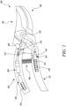
- FIG. 1 illustrates a power-assisted cutting tool 100.
- the power-assisted cutting tool 100 of the present disclosure is illustrated as a secateur, however, the present disclosure may be readily applied to any cutting tool 100 such as, but not limited to, a lopper, shear, scissor etc. with two or more cutting edges.
- the power-assisted cutting tool 100 includes a first cutting element 110 attached to a first handle 112.
- the power-assisted cutting tool 100 includes a second cutting element 130 attached to a second handle 132. Further, the second cutting element 130 is pivotally coupled to the first cutting element 110 at a pivot 120.
- the first cutting element 110 and the second cutting element 130 together perform a cutting action on an object (such as a branch, not shown) placed between them.
- the power-assisted cutting tool 100 includes a drive unit 170 operatively coupled to at least one of the first cutting element 110 and the second cutting element 130.
- the drive unit 170 is operatively coupled to the first cutting element 110 only.
- the drive unit 170 is operatively coupled to the second cutting element 130 only.
- the drive unit 170 is operatively coupled to both the first cutting element 110 and the second cutting element 130.
- the present disclosure illustrates the drive unit 170 powered by a second battery 152 housed within the second handle 132.
- the drive unit 170 may be housed anywhere within the cutting tool 100 and all such variations have been contemplated and are well within the scope of the present disclosure.
- the drive unit 170 selectively provides a supplemental motor 150 force to assist a movement of at least one of the first cutting element 110 and the second cutting element 130 to perform the cutting action.
- the power-assisted cutting tool 100 includes a user interface 140 to measure a hand force applied by a user, and generate a signal indicative of the measured hand force.
- the user interface 140 is powered by a first battery 146 housed within the first handle 112.
- the power-assisted cutting tool 100 includes a controller 190 communicably coupled to the user interface 140 and the drive unit 170, as illustrated by dashed lines in FIGS. 1 , 2 .
- the controller 190 receives the signal indicative of the measured hand force and actuates the drive unit 170 based on the received signal.
- the controller 190 is shown housed within the second handle 132, however it may be housed anywhere within the cutting tool 100, as will be evident to a person having ordinary knowledge in the art.
- the controller 190 adjusts the operation of the drive unit 170 to provide the supplemental motor force based on the measured hand force.
- the controller 190, the user interface 140, and the drive unit 170 may be powered by any or both of the first battery 146, the second battery 152 depending upon implementation needs (say run time, service life and the like) of the cutting tool 100.
- the user of the cutting tool may be prompted status(es) of the first battery 146, the second battery 152 (alternatively referred to as a battery hereinafter) during powering by the supplemental motor force or while configuring of the cutting tool 100 by the user for any desired working profile of the cutting tool 100 as explained in more details later in FIGS. 4a to 4h .
- the power-assisted cutting tool 100 is configured such that the controller 190 actuates the drive unit 170 to provide the supplemental motor force.
- the supplemental motor force is provided such that a magnitude of the supplemental motor force is at least one of a continuous variable and a discreet variable.
- the supplemental motor force is a continuous variable to attain a plurality of different values within a pre-determined force range when the drive unit 170 is assisting the movement of at least one of the first cutting element 110 and the second cutting element 130 to perform the cutting action.
- the pre-determined force range may be defined between an upper limit and a lower limit. Magnitude of the supplemental motor force as a continuous variable may vary between the upper limit and the lower limit attaining any value therebetween. Magnitude of the supplemental motor force may remain constant or vary between plurality of values based on application requirements.
- the supplemental motor force is a discreet variable to attain a plurality of different values within a pre-determined force range when the drive unit 170 is assisting the movement of at least one of the first cutting element 110 and the second cutting element 130 to perform the cutting action.
- the pre-determined force range may be defined between an upper limit and a lower limit. Magnitude of the supplemental motor force as a discreet variable may vary between the upper limit and the lower limit attaining discreet values therebetween. Magnitude of the supplemental motor force may remain constant or vary between plurality of values based on application requirements.
- FIG. 2 illustrates the power-assisted cutting tool 100 in an actuated state, in accordance with an embodiment of the present invention.
- the user interface 140 includes a hall sensor 140, spring 142 and a magnet 144 to measure the hand force applied by the user. This makes operation of the power-assisted cutting tool 100 more precise and dependent upon user profiles/dynamics (i.e. the hand force applied).
- the spring 142 and the magnet 144 change their relative positions with respect to the hall sensor 140 on sensing the hand force by the user as depicted here, in comparison to FIG. 1 .
- the cutting tool 100 may include sensors in addition or alternatively to the hall sensor 140, spring 142 and the magnet 144 to gauge/measure data relevant to the user for more efficient operation of the cutting tool 100.
- the cutting tool 100 may include sensors such as, but not limited to, displacement sensor, force sensor, vitals sensor (heartbeat etc.) which may communicate with the controller 170 to further optimize the operation of the cutting tool 100 as per the user or for any other consideration.
- the drive unit 170 includes a motor 150, a gearbox 160 and a clutch 170 and wire 172 arrangement to selectively provide the supplemental motor force. This arrangement ensures a smooth and safe application of the supplemental motor force to assist in operation of the power-assisted cutting tool 100. Further, the drive unit 170 is actuated to supply the supplemental motor force when the hand force measured by the user interface 140 is above a threshold value. When the drive unit 170 is actuated, the motor 150 starts working to actuate the clutch 170 in winding the wire 172 such that the wire 172 works to pull the first handle 112 towards the second handle 132, by a magnitude in equivalent to the supplemental motor force and thereby assisting the user in the cutting action.
- the threshold value may be user selected and/or user-centric to make the power-assisted cutting tool 100 applicable for various users, from a child to old age individuals.
- the cutting tool 100 includes a means (such as a button, knob, or switch, not shown) to activate or deactivate the drive unit 170.
- the drive unit 170 may be deactivated for instances which may require to save/extend battery life or allow uninterrupted operation of the power-assisted cutting tool 100 for low battery conditions. In such instances of the deactivated drive unit 170, the motor 150 will remain in a disengaged state leading to a purely user-based cutting action by the cutting tool 100, without any supplemental motor force.
- the first cutting element 110 and the second cutting element 130 are biased by a biasing spring 180, which ensures that the first cutting element 110 and the second cutting element 130, and the first handle 112 and the second handle 132 respectively, move to their original position in absence of any external force.
- the biasing spring 180 biases the first handle 112 to move away from the second handle 132 (say after end of the cutting action) and towards its original position which was the relative position of the first handle 112 and the second handle 132 before start of the cutting action.
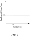
- FIG. 3 shows a graphical representation for supplemental motor force provided for a use scenario of a conventional power-assisted cutting tool (not shown) as known in prior art.
- the graph depicts a scenario where the supplemental motor force has a constant maximum value SMF 0 , when the hand force applied (by the user) is more than the threshold HF 0 .
- the conventional power-assisted cutting tool may be so configured that a driving means (say similar to the drive unit 170 of the present disclosure) actuates only when the hand force is more than the threshold HF 0 .
- the drive force reaches the threshold HF 0 , it is supplemented by the constant maximum value SMF 0 .
- Such a setting of the conventional power-assisted cutting tool, with the constant maximum value SMF 0 may be relevant for experienced users who may prefer to utilize the hand power initially and then only desire the hand force to be supplemented by a pre-set magnitude of the supplemental motor force i.e. the constant maximum value SMF 0 , in accordance with representation shown in latest figure.
- Such a setting may cause jerk or discomfort for a user due to sudden supply of power and may not be desirable.
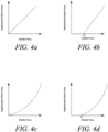
- FIG. 4 a to 4 h shows graphical representations for supplemental motor force provided for different use scenarios of the power-assisted cutting tool 100, in accordance with embodiments of the present invention.
- the graphical representations depict different scenarios plotting the hand force along the x-axis while the supplemental motor force is along the y-axis.
- FIGS. 4 a , b illustrate scenarios where the hand force and the supplemental motor force share a linear relationship.
- the hand force applied is directly proportional to the supplemental motor force applied by the drive unit 170 as per FIG. 4 a.
- FIG. 4 a may find relevance where a user (say a child, old age individuals etc.) will expect assistance by the supplemental motor force throughout and from beginning of the cutting action.
- the cutting tool 100 may be so configured that the drive unit 170 actuates only when the hand force is more than a threshold HF 0 .
- This provision of the threshold HF 0 may find more relevance where the user may be expected to utilize the hand power and only make use of the supplemental motor force, after the threshold HF 0 from consideration such as saving battery use/status or for any other reason.
- FIGS. 4 c , d the graphs depict scenarios where the hand force and the supplemental motor force share a non-linear relationship.
- the hand force applied needs to be supplemented by a substantially larger magnitude of the supplemental motor force applied by the drive unit 170 as per the present figures.
- FIG. 4 c may find relevance where a user (say a child, old age individuals etc.) will expect assistance by a high magnitude of the supplemental motor force throughout and from beginning of the cutting action.
- the cutting tool 100 may be so configured that the drive unit 170 actuates only when the hand force is more than a threshold HF 0 .
- This provision of the threshold HF 0 may find more relevance where the user force may be more expected and would prefer to utilize the hand power initially and then the hand force may be later supplemented by a comparatively larger magnitude of the supplemental motor force, in accordance with representation shown in FIG. 4 d.
- FIG. 4 d may be utilized to save battery life/power or any other consideration, so that the motor 150 comes into picture only after the threshold is reached by the hand force, to be supplemented by the supplemental motor force.
- the curve shown is illustrated as a parabolic curve. However, it should be contemplated that any other such non-linear relationship may also be observed without limiting the scope of the present disclosure. For example, a hyperbolic curve, a partially elliptical curve, or a combination of plurality of curves may also be envisioned.
- FIGS. 4 e to 4 h the graphs depict scenarios where cutting takes place only post application of a threshold value of the hand force along with a constant maximum value SMF 0 of the supplemental motor force.
- multiple scenarios have been contemplated, starting from FIGS. 4 e , 4 f where the supplemental motor force is linearly proportional and non-linearly proportional with respect to the hand force, respectively.
- Such scenarios may be applicable for high force/intensity cutting or with users requiring substantial assistance form the drive unit 170, for the supplemental motor force.
- the cutting tool 100 may be configured such that the drive unit 170 and the controller 190 are pre-set that after a lapse of a fixed time ( T1, T2 for FIGS. 4 g , h respectively, or a pre-set amount of the supplemental motor force or battery power and the like) of the cutting action, the supplemental motor force becomes constant SCF 1 , SCF 2 for FIGS.
Landscapes
- Life Sciences & Earth Sciences (AREA)
- Forests & Forestry (AREA)
- Engineering & Computer Science (AREA)
- Mechanical Engineering (AREA)
- Biodiversity & Conservation Biology (AREA)
- Ecology (AREA)
- Environmental Sciences (AREA)
- Sawing (AREA)
- Surgical Instruments (AREA)
- Scissors And Nippers (AREA)
- Portable Power Tools In General (AREA)
Claims (5)
- Ein kraftunterstütztes Schneidwerkzeug (100), das Folgendes umfasst:ein erstes Schneidelement (110);ein zweites Schneidelement (130), das schwenkbar mit dem ersten Schneidelement (110) gekoppelt ist, wobei das erste Schneidelement (110) und das zweite Schneidelement (130) zusammen einen Schneidevorgang an einem dazwischen platzierten Objekt durchführen; eine Antriebseinheit (170), die funktionsmäßig mit dem ersten Schneidelement (110) und/oder dem zweiten Schneidelement (130) gekoppelt ist, wobei die Antriebseinheit (170) so ausgebildet ist, dass sie selektiv eine Kraft eines Zusatzmotors (150) bereitstellt, um eine Bewegung des ersten Schneidelements (110) und/oder des zweiten Schneidelements (130) zu unterstützen, um den Schneidevorgang durchzuführen; eine Benutzerschnittstelle (140), die so ausgebildet ist, dass sie eine von einem Benutzer aufgebrachte Handkraft misst und ein die gemessene Handkraft anzeigendes Signal erzeugt; und eine Steuerung (190), die kommunizierend mit der Benutzerschnittstelle (140) und der Antriebseinheit (170) gekoppelt ist, wobei die Steuerung (190) so ausgebildet ist, dass sie das die gemessene Handkraft anzeigende Signal empfängt und die Antriebseinheit (170) auf der Grundlage des empfangenen Signals betätigt; undwobei die Steuerung (190) so ausgebildet ist, dass sie den Betrieb der Antriebseinheit (170) anpasst, um die Kraft des Zusatzmotors (150) auf der Grundlage der gemessenen Handkraft bereitzustellen; undwobei die Steuerung (190) die Antriebseinheit (170) so ansteuert, dass eine Größe der Kraft des Zusatzmotors (150) mindestens eine der folgenden ist:eine kontinuierliche Variable, die so ausgebildet ist, dass sie eine Vielzahl verschiedener Werte innerhalb eines vorbestimmten Kraftbereichs erreicht, wenn die Antriebseinheit (170) die Bewegung von mindestens einem von dem ersten Schneidelement (110) und dem zweiten Schneidelement (130) unterstützt, um den Schneidvorgang durchzuführen; und eine diskrete Variable, die so ausgebildet ist, dass sie eine Vielzahl verschiedener Werte innerhalb eines vorbestimmten Kraftbereichs erreicht, wenn die Antriebseinheit (170) die Bewegung von mindestens einem von dem ersten Schneidelement (110) und dem zweiten Schneidelement (130) unterstützt, um den Schneidvorgang durchzuführen;dadurch gekennzeichnet, dass:
die Benutzerschnittstelle (140) einen Hall-Sensor (140) und einen Magneten (144) enthält, um die vom Benutzer aufgebrachte Handkraft zu messen. - Das kraftunterstützte Schneidwerkzeug (100) nach Anspruch 1, wobei die Antriebseinheit (170) einen Motor (150), ein Getriebe (160) und eine Anordnung aus Kupplung (170) und Draht (172) umfasst, um selektiv die zusätzliche Kraft des Motors (150) bereitzustellen.
- Das kraftunterstützte Schneidwerkzeug (100) nach Anspruch 1, wobei das Schneidwerkzeug (100) eine Einrichtung zum Aktivieren oder Deaktivieren der Antriebseinheit (170) umfasst.
- Das Kraftunterstützte Schneidwerkzeug (100) nach Anspruch 1, wobei die Antriebseinheit (170) betätigt wird, um die Kraft des Zusatzmotors (150) zu liefern, wenn die von der Benutzerschnittstelle (140) gemessene Handkraft über einem Schwellenwert liegt.
- Das kraftunterstützte Schneidwerkzeug (100) nach Anspruch 1, wobei das erste Schneidelement (110) und das zweite Schneidelement (130) durch eine Vorspannfeder (180) vorgespannt sind, die sicherstellt, dass sich das erste Schneidelement (110) und das zweite Schneidelement (130) in ihre ursprüngliche Position bewegen, wenn keine äußere Kraft vorhanden ist.
Priority Applications (1)
| Application Number | Priority Date | Filing Date | Title |
|---|---|---|---|
| EP23169055.3A EP4245122B1 (de) | 2019-06-03 | 2019-12-11 | Motorunterstütztes schneidwerkzeug |
Applications Claiming Priority (2)
| Application Number | Priority Date | Filing Date | Title |
|---|---|---|---|
| DE102019003846 | 2019-06-03 | ||
| PCT/EP2019/084654 WO2020244794A1 (en) | 2019-06-03 | 2019-12-11 | Power-assisted cutting tool |
Related Child Applications (2)
| Application Number | Title | Priority Date | Filing Date |
|---|---|---|---|
| EP23169055.3A Division-Into EP4245122B1 (de) | 2019-06-03 | 2019-12-11 | Motorunterstütztes schneidwerkzeug |
| EP23169055.3A Division EP4245122B1 (de) | 2019-06-03 | 2019-12-11 | Motorunterstütztes schneidwerkzeug |
Publications (2)
| Publication Number | Publication Date |
|---|---|
| EP3976325A1 EP3976325A1 (de) | 2022-04-06 |
| EP3976325B1 true EP3976325B1 (de) | 2023-08-23 |
Family
ID=69105769
Family Applications (2)
| Application Number | Title | Priority Date | Filing Date |
|---|---|---|---|
| EP23169055.3A Active EP4245122B1 (de) | 2019-06-03 | 2019-12-11 | Motorunterstütztes schneidwerkzeug |
| EP19831997.2A Active EP3976325B1 (de) | 2019-06-03 | 2019-12-11 | Motorunterstütztes schneidwerkzeug |
Family Applications Before (1)
| Application Number | Title | Priority Date | Filing Date |
|---|---|---|---|
| EP23169055.3A Active EP4245122B1 (de) | 2019-06-03 | 2019-12-11 | Motorunterstütztes schneidwerkzeug |
Country Status (6)
| Country | Link |
|---|---|
| EP (2) | EP4245122B1 (de) |
| CN (1) | CN113924197A (de) |
| FI (2) | FI3976325T3 (de) |
| PL (2) | PL3976325T3 (de) |
| TW (1) | TWI842906B (de) |
| WO (1) | WO2020244794A1 (de) |
Families Citing this family (2)
| Publication number | Priority date | Publication date | Assignee | Title |
|---|---|---|---|---|
| US10172292B2 (en) | 2016-10-17 | 2019-01-08 | Robert Bosch Gmbh | Cutting device |
| EP4052564A1 (de) * | 2021-03-05 | 2022-09-07 | Husqvarna Ab | Schneidwerkzeug |
Family Cites Families (9)
| Publication number | Priority date | Publication date | Assignee | Title |
|---|---|---|---|---|
| JP2001178848A (ja) * | 1999-12-24 | 2001-07-03 | Sanshiro Takamiya | 手首の機能改善具 |
| JP5332662B2 (ja) * | 2009-01-30 | 2013-11-06 | マックス株式会社 | 電動はさみ |
| DE102010016296B4 (de) * | 2010-04-01 | 2012-05-03 | AR&T, Applied Robot & Technologies UG (haftungsbeschränkt) | Hilfskraftbetätigte Handschere und Verfahren zu deren Betrieb |
| CN201754179U (zh) * | 2010-07-15 | 2011-03-02 | 华南理工大学 | 一种夹持式磁通量检测探头 |
| CH710461A1 (de) * | 2014-12-11 | 2016-06-15 | Spanset Inter Ag | Vorrichtung und Verfahren zur Messung der Zugspannung in einem Spanngurt. |
| US9766142B1 (en) * | 2015-03-20 | 2017-09-19 | Cory S. Hague | Magnetic force sensor systems and methods |
| DE102015206959A1 (de) * | 2015-04-17 | 2016-10-20 | Robert Bosch Gmbh | Schneidevorrichtung |
| DE102016211974B4 (de) * | 2016-06-30 | 2024-10-17 | Robert Bosch Gmbh | Schneidvorrichtung |
| CN206416169U (zh) * | 2017-01-17 | 2017-08-18 | 慧灵科技(深圳)有限公司 | 一种带有力反馈机构且精确控制夹取力的电动手爪 |
-
2019
- 2019-12-11 EP EP23169055.3A patent/EP4245122B1/de active Active
- 2019-12-11 EP EP19831997.2A patent/EP3976325B1/de active Active
- 2019-12-11 PL PL19831997.2T patent/PL3976325T3/pl unknown
- 2019-12-11 WO PCT/EP2019/084654 patent/WO2020244794A1/en not_active Ceased
- 2019-12-11 FI FIEP19831997.2T patent/FI3976325T3/fi active
- 2019-12-11 FI FIEP23169055.3T patent/FI4245122T3/fi active
- 2019-12-11 PL PL23169055.3T patent/PL4245122T3/pl unknown
- 2019-12-11 CN CN201980097127.0A patent/CN113924197A/zh active Pending
-
2020
- 2020-06-02 TW TW109118491A patent/TWI842906B/zh active
Also Published As
| Publication number | Publication date |
|---|---|
| TWI842906B (zh) | 2024-05-21 |
| WO2020244794A1 (en) | 2020-12-10 |
| CN113924197A (zh) | 2022-01-11 |
| PL4245122T3 (pl) | 2024-07-22 |
| EP3976325A1 (de) | 2022-04-06 |
| FI4245122T3 (fi) | 2024-06-28 |
| FI3976325T3 (fi) | 2023-10-06 |
| EP4245122A3 (de) | 2023-10-18 |
| EP4245122B1 (de) | 2024-05-29 |
| PL3976325T3 (pl) | 2023-12-04 |
| EP4245122A2 (de) | 2023-09-20 |
| TW202044981A (zh) | 2020-12-16 |
Similar Documents
| Publication | Publication Date | Title |
|---|---|---|
| EP3976325B1 (de) | Motorunterstütztes schneidwerkzeug | |
| US11185956B2 (en) | Force responsive power tool | |
| AU2020200319B2 (en) | Systems and methods for configuring a reciprocating saw | |
| JP5914809B2 (ja) | 電動工具 | |
| CN105605210B (zh) | 步行式作业机的变速控制系统及该作业机的速度变化方法 | |
| EP3155887B1 (de) | Elektrowerkzeug und steuerungsverfahren dafür | |
| US20120169256A1 (en) | Electric power tool | |
| CN205600590U (zh) | 可快速切换扭力的扭力扳手 | |
| US9577567B2 (en) | Method for operating a work apparatus having an electric motor | |
| JP2008022757A (ja) | 電動式ハサミ | |
| JP2019116307A (ja) | 結束機 | |
| US20180370011A1 (en) | Hand-Held Power Tool Comprising a Gearshift Unit | |
| BR112017007570B1 (pt) | Processo e dispositivo de comando para equipamento com motor e ferramenta elétrica portátil | |
| JP6226420B2 (ja) | 電動アシスト機能付きはさみ | |
| EP2779413A2 (de) | Antriebsstrangsystem und Verfahren zum Antrieb eines Fahrzeugs | |
| CN106385938B (zh) | 割草机 | |
| JP2020000064A (ja) | 田植機 | |
| CN104723290A (zh) | 电动工具扭力输出的控制装置及其控制方法 | |
| JP2013064469A (ja) | ギアシフト装置 | |
| WO2015025222A2 (en) | Tactile feel control device | |
| JP6985929B2 (ja) | 結束機 | |
| US9726729B2 (en) | Method for controlling electric motor by trigger | |
| CN115245087B (zh) | 后走式自推工作机 | |
| US20150053447A1 (en) | Device for detecting the presence of a removable tool of a linear actuator | |
| JP2005006384A (ja) | 電動工具用スイッチおよび同スイッチを用いた電動工具 |
Legal Events
| Date | Code | Title | Description |
|---|---|---|---|
| STAA | Information on the status of an ep patent application or granted ep patent |
Free format text: STATUS: UNKNOWN |
|
| STAA | Information on the status of an ep patent application or granted ep patent |
Free format text: STATUS: THE INTERNATIONAL PUBLICATION HAS BEEN MADE |
|
| PUAI | Public reference made under article 153(3) epc to a published international application that has entered the european phase |
Free format text: ORIGINAL CODE: 0009012 |
|
| STAA | Information on the status of an ep patent application or granted ep patent |
Free format text: STATUS: REQUEST FOR EXAMINATION WAS MADE |
|
| 17P | Request for examination filed |
Effective date: 20211104 |
|
| AK | Designated contracting states |
Kind code of ref document: A1 Designated state(s): AL AT BE BG CH CY CZ DE DK EE ES FI FR GB GR HR HU IE IS IT LI LT LU LV MC MK MT NL NO PL PT RO RS SE SI SK SM TR |
|
| DAV | Request for validation of the european patent (deleted) | ||
| DAX | Request for extension of the european patent (deleted) | ||
| GRAP | Despatch of communication of intention to grant a patent |
Free format text: ORIGINAL CODE: EPIDOSNIGR1 |
|
| STAA | Information on the status of an ep patent application or granted ep patent |
Free format text: STATUS: GRANT OF PATENT IS INTENDED |
|
| GRAJ | Information related to disapproval of communication of intention to grant by the applicant or resumption of examination proceedings by the epo deleted |
Free format text: ORIGINAL CODE: EPIDOSDIGR1 |
|
| STAA | Information on the status of an ep patent application or granted ep patent |
Free format text: STATUS: REQUEST FOR EXAMINATION WAS MADE |
|
| INTG | Intention to grant announced |
Effective date: 20230221 |
|
| INTC | Intention to grant announced (deleted) | ||
| GRAP | Despatch of communication of intention to grant a patent |
Free format text: ORIGINAL CODE: EPIDOSNIGR1 |
|
| STAA | Information on the status of an ep patent application or granted ep patent |
Free format text: STATUS: GRANT OF PATENT IS INTENDED |
|
| GRAS | Grant fee paid |
Free format text: ORIGINAL CODE: EPIDOSNIGR3 |
|
| GRAA | (expected) grant |
Free format text: ORIGINAL CODE: 0009210 |
|
| STAA | Information on the status of an ep patent application or granted ep patent |
Free format text: STATUS: THE PATENT HAS BEEN GRANTED |
|
| INTG | Intention to grant announced |
Effective date: 20230705 |
|
| AK | Designated contracting states |
Kind code of ref document: B1 Designated state(s): AL AT BE BG CH CY CZ DE DK EE ES FI FR GB GR HR HU IE IS IT LI LT LU LV MC MK MT NL NO PL PT RO RS SE SI SK SM TR |
|
| REG | Reference to a national code |
Ref country code: GB Ref legal event code: FG4D |
|
| REG | Reference to a national code |
Ref country code: CH Ref legal event code: EP |
|
| REG | Reference to a national code |
Ref country code: DE Ref legal event code: R096 Ref document number: 602019035789 Country of ref document: DE |
|
| REG | Reference to a national code |
Ref country code: IE Ref legal event code: FG4D |
|
| REG | Reference to a national code |
Ref country code: FI Ref legal event code: FGE |
|
| REG | Reference to a national code |
Ref country code: LT Ref legal event code: MG9D |
|
| REG | Reference to a national code |
Ref country code: NL Ref legal event code: MP Effective date: 20230823 |
|
| REG | Reference to a national code |
Ref country code: AT Ref legal event code: MK05 Ref document number: 1602043 Country of ref document: AT Kind code of ref document: T Effective date: 20230823 |
|
| PG25 | Lapsed in a contracting state [announced via postgrant information from national office to epo] |
Ref country code: GR Free format text: LAPSE BECAUSE OF FAILURE TO SUBMIT A TRANSLATION OF THE DESCRIPTION OR TO PAY THE FEE WITHIN THE PRESCRIBED TIME-LIMIT Effective date: 20231124 |
|
| PG25 | Lapsed in a contracting state [announced via postgrant information from national office to epo] |
Ref country code: IS Free format text: LAPSE BECAUSE OF FAILURE TO SUBMIT A TRANSLATION OF THE DESCRIPTION OR TO PAY THE FEE WITHIN THE PRESCRIBED TIME-LIMIT Effective date: 20231223 |
|
| PG25 | Lapsed in a contracting state [announced via postgrant information from national office to epo] |
Ref country code: SE Free format text: LAPSE BECAUSE OF FAILURE TO SUBMIT A TRANSLATION OF THE DESCRIPTION OR TO PAY THE FEE WITHIN THE PRESCRIBED TIME-LIMIT Effective date: 20230823 Ref country code: RS Free format text: LAPSE BECAUSE OF FAILURE TO SUBMIT A TRANSLATION OF THE DESCRIPTION OR TO PAY THE FEE WITHIN THE PRESCRIBED TIME-LIMIT Effective date: 20230823 Ref country code: PT Free format text: LAPSE BECAUSE OF FAILURE TO SUBMIT A TRANSLATION OF THE DESCRIPTION OR TO PAY THE FEE WITHIN THE PRESCRIBED TIME-LIMIT Effective date: 20231226 Ref country code: NO Free format text: LAPSE BECAUSE OF FAILURE TO SUBMIT A TRANSLATION OF THE DESCRIPTION OR TO PAY THE FEE WITHIN THE PRESCRIBED TIME-LIMIT Effective date: 20231123 Ref country code: NL Free format text: LAPSE BECAUSE OF FAILURE TO SUBMIT A TRANSLATION OF THE DESCRIPTION OR TO PAY THE FEE WITHIN THE PRESCRIBED TIME-LIMIT Effective date: 20230823 Ref country code: LV Free format text: LAPSE BECAUSE OF FAILURE TO SUBMIT A TRANSLATION OF THE DESCRIPTION OR TO PAY THE FEE WITHIN THE PRESCRIBED TIME-LIMIT Effective date: 20230823 Ref country code: LT Free format text: LAPSE BECAUSE OF FAILURE TO SUBMIT A TRANSLATION OF THE DESCRIPTION OR TO PAY THE FEE WITHIN THE PRESCRIBED TIME-LIMIT Effective date: 20230823 Ref country code: IS Free format text: LAPSE BECAUSE OF FAILURE TO SUBMIT A TRANSLATION OF THE DESCRIPTION OR TO PAY THE FEE WITHIN THE PRESCRIBED TIME-LIMIT Effective date: 20231223 Ref country code: HR Free format text: LAPSE BECAUSE OF FAILURE TO SUBMIT A TRANSLATION OF THE DESCRIPTION OR TO PAY THE FEE WITHIN THE PRESCRIBED TIME-LIMIT Effective date: 20230823 Ref country code: GR Free format text: LAPSE BECAUSE OF FAILURE TO SUBMIT A TRANSLATION OF THE DESCRIPTION OR TO PAY THE FEE WITHIN THE PRESCRIBED TIME-LIMIT Effective date: 20231124 Ref country code: AT Free format text: LAPSE BECAUSE OF FAILURE TO SUBMIT A TRANSLATION OF THE DESCRIPTION OR TO PAY THE FEE WITHIN THE PRESCRIBED TIME-LIMIT Effective date: 20230823 |
|
| PG25 | Lapsed in a contracting state [announced via postgrant information from national office to epo] |
Ref country code: ES Free format text: LAPSE BECAUSE OF FAILURE TO SUBMIT A TRANSLATION OF THE DESCRIPTION OR TO PAY THE FEE WITHIN THE PRESCRIBED TIME-LIMIT Effective date: 20230823 |
|
| PG25 | Lapsed in a contracting state [announced via postgrant information from national office to epo] |
Ref country code: SM Free format text: LAPSE BECAUSE OF FAILURE TO SUBMIT A TRANSLATION OF THE DESCRIPTION OR TO PAY THE FEE WITHIN THE PRESCRIBED TIME-LIMIT Effective date: 20230823 Ref country code: RO Free format text: LAPSE BECAUSE OF FAILURE TO SUBMIT A TRANSLATION OF THE DESCRIPTION OR TO PAY THE FEE WITHIN THE PRESCRIBED TIME-LIMIT Effective date: 20230823 Ref country code: ES Free format text: LAPSE BECAUSE OF FAILURE TO SUBMIT A TRANSLATION OF THE DESCRIPTION OR TO PAY THE FEE WITHIN THE PRESCRIBED TIME-LIMIT Effective date: 20230823 Ref country code: EE Free format text: LAPSE BECAUSE OF FAILURE TO SUBMIT A TRANSLATION OF THE DESCRIPTION OR TO PAY THE FEE WITHIN THE PRESCRIBED TIME-LIMIT Effective date: 20230823 Ref country code: DK Free format text: LAPSE BECAUSE OF FAILURE TO SUBMIT A TRANSLATION OF THE DESCRIPTION OR TO PAY THE FEE WITHIN THE PRESCRIBED TIME-LIMIT Effective date: 20230823 Ref country code: CZ Free format text: LAPSE BECAUSE OF FAILURE TO SUBMIT A TRANSLATION OF THE DESCRIPTION OR TO PAY THE FEE WITHIN THE PRESCRIBED TIME-LIMIT Effective date: 20230823 Ref country code: SK Free format text: LAPSE BECAUSE OF FAILURE TO SUBMIT A TRANSLATION OF THE DESCRIPTION OR TO PAY THE FEE WITHIN THE PRESCRIBED TIME-LIMIT Effective date: 20230823 |
|
| REG | Reference to a national code |
Ref country code: DE Ref legal event code: R097 Ref document number: 602019035789 Country of ref document: DE |
|
| P01 | Opt-out of the competence of the unified patent court (upc) registered |
Effective date: 20240419 |
|
| PG25 | Lapsed in a contracting state [announced via postgrant information from national office to epo] |
Ref country code: IT Free format text: LAPSE BECAUSE OF FAILURE TO SUBMIT A TRANSLATION OF THE DESCRIPTION OR TO PAY THE FEE WITHIN THE PRESCRIBED TIME-LIMIT Effective date: 20230823 |
|
| PLBE | No opposition filed within time limit |
Free format text: ORIGINAL CODE: 0009261 |
|
| STAA | Information on the status of an ep patent application or granted ep patent |
Free format text: STATUS: NO OPPOSITION FILED WITHIN TIME LIMIT |
|
| 26N | No opposition filed |
Effective date: 20240524 |
|
| PG25 | Lapsed in a contracting state [announced via postgrant information from national office to epo] |
Ref country code: SI Free format text: LAPSE BECAUSE OF FAILURE TO SUBMIT A TRANSLATION OF THE DESCRIPTION OR TO PAY THE FEE WITHIN THE PRESCRIBED TIME-LIMIT Effective date: 20230823 |
|
| REG | Reference to a national code |
Ref country code: CH Ref legal event code: PL |
|
| PG25 | Lapsed in a contracting state [announced via postgrant information from national office to epo] |
Ref country code: LU Free format text: LAPSE BECAUSE OF NON-PAYMENT OF DUE FEES Effective date: 20231211 |
|
| PG25 | Lapsed in a contracting state [announced via postgrant information from national office to epo] |
Ref country code: MC Free format text: LAPSE BECAUSE OF FAILURE TO SUBMIT A TRANSLATION OF THE DESCRIPTION OR TO PAY THE FEE WITHIN THE PRESCRIBED TIME-LIMIT Effective date: 20230823 |
|
| REG | Reference to a national code |
Ref country code: BE Ref legal event code: MM Effective date: 20231231 |
|
| PG25 | Lapsed in a contracting state [announced via postgrant information from national office to epo] |
Ref country code: MC Free format text: LAPSE BECAUSE OF FAILURE TO SUBMIT A TRANSLATION OF THE DESCRIPTION OR TO PAY THE FEE WITHIN THE PRESCRIBED TIME-LIMIT Effective date: 20230823 Ref country code: LU Free format text: LAPSE BECAUSE OF NON-PAYMENT OF DUE FEES Effective date: 20231211 |
|
| REG | Reference to a national code |
Ref country code: IE Ref legal event code: MM4A |
|
| PG25 | Lapsed in a contracting state [announced via postgrant information from national office to epo] |
Ref country code: IE Free format text: LAPSE BECAUSE OF NON-PAYMENT OF DUE FEES Effective date: 20231211 |
|
| PG25 | Lapsed in a contracting state [announced via postgrant information from national office to epo] |
Ref country code: BE Free format text: LAPSE BECAUSE OF NON-PAYMENT OF DUE FEES Effective date: 20231231 |
|
| PG25 | Lapsed in a contracting state [announced via postgrant information from national office to epo] |
Ref country code: CH Free format text: LAPSE BECAUSE OF NON-PAYMENT OF DUE FEES Effective date: 20231231 |
|
| PG25 | Lapsed in a contracting state [announced via postgrant information from national office to epo] |
Ref country code: IE Free format text: LAPSE BECAUSE OF NON-PAYMENT OF DUE FEES Effective date: 20231211 Ref country code: CH Free format text: LAPSE BECAUSE OF NON-PAYMENT OF DUE FEES Effective date: 20231231 Ref country code: BE Free format text: LAPSE BECAUSE OF NON-PAYMENT OF DUE FEES Effective date: 20231231 |
|
| PG25 | Lapsed in a contracting state [announced via postgrant information from national office to epo] |
Ref country code: BG Free format text: LAPSE BECAUSE OF FAILURE TO SUBMIT A TRANSLATION OF THE DESCRIPTION OR TO PAY THE FEE WITHIN THE PRESCRIBED TIME-LIMIT Effective date: 20230823 |
|
| PG25 | Lapsed in a contracting state [announced via postgrant information from national office to epo] |
Ref country code: BG Free format text: LAPSE BECAUSE OF FAILURE TO SUBMIT A TRANSLATION OF THE DESCRIPTION OR TO PAY THE FEE WITHIN THE PRESCRIBED TIME-LIMIT Effective date: 20230823 |
|
| PGFP | Annual fee paid to national office [announced via postgrant information from national office to epo] |
Ref country code: DE Payment date: 20241111 Year of fee payment: 6 |
|
| PGFP | Annual fee paid to national office [announced via postgrant information from national office to epo] |
Ref country code: PL Payment date: 20241009 Year of fee payment: 6 Ref country code: FI Payment date: 20241122 Year of fee payment: 6 |
|
| PGFP | Annual fee paid to national office [announced via postgrant information from national office to epo] |
Ref country code: GB Payment date: 20241115 Year of fee payment: 6 |
|
| PGFP | Annual fee paid to national office [announced via postgrant information from national office to epo] |
Ref country code: FR Payment date: 20241115 Year of fee payment: 6 |
|
| PG25 | Lapsed in a contracting state [announced via postgrant information from national office to epo] |
Ref country code: CY Free format text: LAPSE BECAUSE OF FAILURE TO SUBMIT A TRANSLATION OF THE DESCRIPTION OR TO PAY THE FEE WITHIN THE PRESCRIBED TIME-LIMIT; INVALID AB INITIO Effective date: 20191211 |
|
| PG25 | Lapsed in a contracting state [announced via postgrant information from national office to epo] |
Ref country code: HU Free format text: LAPSE BECAUSE OF FAILURE TO SUBMIT A TRANSLATION OF THE DESCRIPTION OR TO PAY THE FEE WITHIN THE PRESCRIBED TIME-LIMIT; INVALID AB INITIO Effective date: 20191211 |