EP3975243A1 - Temperature control unit - Google Patents
Temperature control unit Download PDFInfo
- Publication number
- EP3975243A1 EP3975243A1 EP20808697.5A EP20808697A EP3975243A1 EP 3975243 A1 EP3975243 A1 EP 3975243A1 EP 20808697 A EP20808697 A EP 20808697A EP 3975243 A1 EP3975243 A1 EP 3975243A1
- Authority
- EP
- European Patent Office
- Prior art keywords
- heat transfer
- transfer medium
- temperature control
- fiber sheet
- metal fiber
- Prior art date
- Legal status (The legal status is an assumption and is not a legal conclusion. Google has not performed a legal analysis and makes no representation as to the accuracy of the status listed.)
- Pending
Links
Images




Classifications
-
- H—ELECTRICITY
- H05—ELECTRIC TECHNIQUES NOT OTHERWISE PROVIDED FOR
- H05K—PRINTED CIRCUITS; CASINGS OR CONSTRUCTIONAL DETAILS OF ELECTRIC APPARATUS; MANUFACTURE OF ASSEMBLAGES OF ELECTRICAL COMPONENTS
- H05K7/00—Constructional details common to different types of electric apparatus
- H05K7/20—Modifications to facilitate cooling, ventilating, or heating
- H05K7/2039—Modifications to facilitate cooling, ventilating, or heating characterised by the heat transfer by conduction from the heat generating element to a dissipating body
-
- H—ELECTRICITY
- H05—ELECTRIC TECHNIQUES NOT OTHERWISE PROVIDED FOR
- H05K—PRINTED CIRCUITS; CASINGS OR CONSTRUCTIONAL DETAILS OF ELECTRIC APPARATUS; MANUFACTURE OF ASSEMBLAGES OF ELECTRICAL COMPONENTS
- H05K7/00—Constructional details common to different types of electric apparatus
- H05K7/20—Modifications to facilitate cooling, ventilating, or heating
- H05K7/20218—Modifications to facilitate cooling, ventilating, or heating using a liquid coolant without phase change in electronic enclosures
- H05K7/20272—Accessories for moving fluid, for expanding fluid, for connecting fluid conduits, for distributing fluid, for removing gas or for preventing leakage, e.g. pumps, tanks or manifolds
-
- H—ELECTRICITY
- H05—ELECTRIC TECHNIQUES NOT OTHERWISE PROVIDED FOR
- H05K—PRINTED CIRCUITS; CASINGS OR CONSTRUCTIONAL DETAILS OF ELECTRIC APPARATUS; MANUFACTURE OF ASSEMBLAGES OF ELECTRICAL COMPONENTS
- H05K7/00—Constructional details common to different types of electric apparatus
- H05K7/20—Modifications to facilitate cooling, ventilating, or heating
- H05K7/20218—Modifications to facilitate cooling, ventilating, or heating using a liquid coolant without phase change in electronic enclosures
- H05K7/20254—Cold plates transferring heat from heat source to coolant
-
- H—ELECTRICITY
- H05—ELECTRIC TECHNIQUES NOT OTHERWISE PROVIDED FOR
- H05K—PRINTED CIRCUITS; CASINGS OR CONSTRUCTIONAL DETAILS OF ELECTRIC APPARATUS; MANUFACTURE OF ASSEMBLAGES OF ELECTRICAL COMPONENTS
- H05K7/00—Constructional details common to different types of electric apparatus
- H05K7/20—Modifications to facilitate cooling, ventilating, or heating
- H05K7/2039—Modifications to facilitate cooling, ventilating, or heating characterised by the heat transfer by conduction from the heat generating element to a dissipating body
- H05K7/20436—Inner thermal coupling elements in heat dissipating housings, e.g. protrusions or depressions integrally formed in the housing
- H05K7/20445—Inner thermal coupling elements in heat dissipating housings, e.g. protrusions or depressions integrally formed in the housing the coupling element being an additional piece, e.g. thermal standoff
- H05K7/20472—Sheet interfaces
-
- H—ELECTRICITY
- H10—SEMICONDUCTOR DEVICES; ELECTRIC SOLID-STATE DEVICES NOT OTHERWISE PROVIDED FOR
- H10W—GENERIC PACKAGES, INTERCONNECTIONS, CONNECTORS OR OTHER CONSTRUCTIONAL DETAILS OF DEVICES COVERED BY CLASS H10
- H10W40/00—Arrangements for thermal protection or thermal control
- H10W40/20—Arrangements for cooling
- H10W40/25—Arrangements for cooling characterised by their materials
- H10W40/258—Metallic materials
-
- H—ELECTRICITY
- H10—SEMICONDUCTOR DEVICES; ELECTRIC SOLID-STATE DEVICES NOT OTHERWISE PROVIDED FOR
- H10W—GENERIC PACKAGES, INTERCONNECTIONS, CONNECTORS OR OTHER CONSTRUCTIONAL DETAILS OF DEVICES COVERED BY CLASS H10
- H10W40/00—Arrangements for thermal protection or thermal control
- H10W40/40—Arrangements for thermal protection or thermal control involving heat exchange by flowing fluids
- H10W40/47—Arrangements for thermal protection or thermal control involving heat exchange by flowing fluids by flowing liquids, e.g. forced water cooling
Definitions
- the present invention relates to a temperature control unit.
- Patent Document 1 discloses a cooling member that has excellent cooling effects, that can easily be made compact and thin, and that allows localized cooling.
- the cooling member has a metal fiber sheet comprising metal fibers, and a cooling mechanism configured to cool the metal fiber sheet, wherein the cooling mechanism is provided with a housing configured to house the metal fiber sheet and a refrigerant-introducing means configured to introduce a refrigerant into the housing.
- Patent Document 1 JP 2019-9433 A
- Patent Document 1 which is an example of the above-mentioned conventional art, there is a possibility that uneven cooling will occur in the case in which the dispersiveness of the refrigerant in the housing is low.
- the same can be said for the case in which the temperature in the housing is to be raised. There is a possibility that uneven heating will occur in the case in which the dispersiveness of a heating medium in the housing is low.
- the present invention was developed in consideration of the above, and an objective of the invention is to obtain a temperature control unit capable of highly uniform temperature control.
- the present invention which solves the above-mentioned problem and achieves the objective, is a temperature control unit comprising: a heat transfer medium introduction port configured to introduce a heat transfer medium from outside; a temperature control mechanism through which the heat transfer medium from the heat transfer medium introduction port passes; and a heat transfer medium discharge port configured to discharge the heat transfer medium from the temperature control mechanism to outside, wherein: the temperature control mechanism comprises a porous metal body; and a housing configured to house the porous metal body; at least one main surface of the housing is exposed to an outer side of the temperature control mechanism, and an inner side of the main surface contacts the porous metal body, thereby exchanging heat between the porous metal body and outside; and a heat transfer medium dispersion area is provided between the heat transfer medium introduction port and the porous metal body.
- a heat transfer medium buffer area is preferably provided between the porous metal body and the heat transfer medium discharge port.
- the porous metal body is preferably a metal fiber sheet configured to include metal fibers.
- the heat transfer medium dispersion area preferably has a shape that is continuously angled so as to widen out from the heat transfer medium introduction port towards both end portions of a heat transfer medium introduction surface of the porous metal body; and the heat transfer medium buffer area preferably has a shape that is continuously angled so as to narrow down from both end portions of a heat transfer medium discharge surface of the metal fiber sheet towards the heat transfer medium discharge port.
- the metal fiber sheet preferably comprises: a first metal fiber sheet arranged on the heat transfer medium introduction port side; and a second metal fiber sheet arranged on the heat transfer medium discharge port side, and a gap is formed between the first metal fiber sheet and the second metal fiber sheet.
- the metal fiber sheet preferably has a shape such that a passage for the heat transfer medium becomes longer in a portion at which the flow rate of the heat transfer medium becomes higher.
- the metal fiber sheet is preferably configured such that the metal fibers are densely arranged in a portion at which the flow rate of the heat transfer medium becomes higher.
- part of the metal fiber sheet is preferably removed to form a flow passage with a meandering shape.
- the housing is preferably configured such that a flow passage for the heat transfer medium becomes narrow in a portion at which the flow rate of the heat transfer medium becomes lower.
- the housing is preferably configured such that a structure blocks part of a flow passage for the heat transfer medium, thereby forming a meandering flow passage.
- a temperature control unit capable of highly uniform temperature control can be obtained.
- Metal fibers refers to fibers in which the main component is a metal.
- copper fibers refers to fibers in which the main component is copper.
- the main component is a metal
- a certain amount of components other than said metal, such as impurities that are unavoidably contained, may be included, as long as the effects of the present invention are not compromised.
- thermo conductivity W/(m ⁇ K)
- TC7000 series laser flash thermal constant measuring device manufactured by Ulvac Riko, Inc.
- average fiber diameter refers to the arithmetic mean of area-based diameters derived by computing the cross-sectional areas perpendicular to the lengthwise direction of the metal fibers based on the perpendicular cross-sections at multiple locations in a metal fiber sheet imaged by a microscope, and computing the diameters of perfect circles having the same areas as said cross-sectional areas.
- the multiple locations may, for example, be twenty locations.
- average fiber length refers to the arithmetic mean of measured values of the lengths of fibers in the lengthwise direction for multiple fibers randomly selected in a microscope image.
- the lengths are the lengths of curves along the fibers.
- the multiple fibers may, for example, be twenty fibers.
- fill rate refers to the proportion of the volume of a fiber sheet occupied by the fiber portions, and is computed from the basis weight and thickness of the fiber sheet, and the true density of the fibers, by means of the equation below.
- the fill rate can be computed by employing a true density value reflecting the compositional ratio of the fibers.
- Fill rate % basis weight of fiber sheet / thickness of fiber sheet ⁇ true density ⁇ 100
- Thickness of the sheet refers, for example, to the arithmetic mean in the case in which the metal fiber sheet has been measured at measurement points by means of an air-based terminal drop-type film thickness gauge (for example, "Digimatic Indicator ID-C112X” manufactured by Mitutoyo Corp.).
- an air-based terminal drop-type film thickness gauge for example, "Digimatic Indicator ID-C112X” manufactured by Mitutoyo Corp.
- “Homogeneity” refers to a sheet comprising fibers having little variance, within the sheet, in the properties of the sheet, such as electrical properties, physical properties, and air permeability properties.
- CV value coefficient of variation
- Vehicle rate refers to the proportion of the volume of a fiber sheet constituted by portions in which voids are present, and is computed from the basis weight and thickness of the fiber sheet, and the true density of the fibers, by means of the equation below.
- the heat transfer medium in the present invention may be a gas, or may be a liquid or the like, and the characteristics thereof are not limited.
- the heat transfer medium in the present invention may be a gas such as air, may be a liquid such as water or alcohol, or may be a fluorine-based compound such as a hydrofluorocarbon or a hydrofluoroether, or the like.
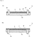
- Fig. 1 is a diagram showing a top view of a temperature control unit 1 according to the present embodiment and a section view along A-A in the top view.
- the temperature control unit 1 shown in Fig. 1 has a heat transfer medium introduction port 2, a temperature control mechanism 3, and a heat transfer medium discharge port 4.
- the heat transfer medium introduction port 2 is a port through which the heat transfer medium is introduced into the temperature control mechanism 3 from outside.
- the heat transfer medium discharge port 4 is a port through which the heat transfer medium in the temperature control mechanism 3 is discharged to outside.
- a static mixer is preferably provided in the heat transfer medium introduction port 2 in order to disperse the heat transfer medium that is introduced.
- the temperature control mechanism 3 is provided with: a metal fiber sheet 6 configured to include metal fibers; a housing 5 configured to house the metal fiber sheet 6; a heat exchange plate 7 provided so that one main surface is exposed to the outer side of the temperature control mechanism 3 and the rear surface of the one main surface contacts the metal fiber sheet 6, thereby exchanging heat between the metal fiber sheet 6 and outside; and a sealing member 8 configured to seal between the housing 5 and the heat exchange plate 7.
- the heat transfer medium introduced through the heat transfer medium introduction port 2 passes through the temperature control mechanism 3 and is discharged through the heat transfer medium discharge port 4.
- the metal fiber sheet 6 may be composed solely of metal fibers or may be configured to include components other than metal fibers.
- Examples of the metal component in the metal fibers include copper, stainless steel, iron, aluminum, nickel, chromium, precious metals, and the like. Among the above, copper, stainless steel, and aluminum are preferable, and copper is particularly preferable.
- precious metals include gold, platinum, silver, palladium, rhodium, iridium, ruthenium, and osmium.
- components other than metal fibers that can be included in the metal fiber sheet 6 include polyethylene terephthalate (PET), polyvinyl alcohol (PVA), polyolefins, polyvinyl chloride (PVC), polyamides, and acrylic, as well as organic substances that provide the fibrous matter with bonding properties and carrier properties.
- PET polyethylene terephthalate
- PVA polyvinyl alcohol
- PVC polyvinyl chloride
- acrylic acrylic
- the form sustainability and the functionality at the time of production of the metal fiber sheet 6 can be aided or improved by including one or more of these organic substances.
- metal fiber sheet 6 multiple metal fibers that are adjacent to each other are preferably bonded together.
- multiple metal fibers are preferably physically fixed to form bonded portions between the multiple metal fibers.
- the multiple metal fibers may be directly fixed or indirectly fixed at the bonded portions. However, gaps should preferably be formed between at least some of the multiple metal fibers constituting the metal fiber sheet 6.
- the multiple metal fibers are preferably sintered because this stabilizes the thermal conductivity and homogeneity of the metal fiber sheet 6.
- the gaps formed between the multiple metal fibers may be formed by entanglement of the metal fibers.
- the void rate in the metal fiber sheet 6 is preferably at least 5% and at most 99%, more preferably at least 10% and at most 98%.
- the thermal conductivity of the metal fiber sheet is preferably at least 5 W/(m ⁇ K).
- the metal fiber sheet 6 need only be a sheet-shaped structure, and may be a nonwoven fabric having multiple metal fibers that are randomly entangled, or may be a woven fabric or a mesh material having regularity.
- the surface of the metal fiber sheet 6 may be flat, or may be made bumpy by performing a corrugation process.
- the basis weight of the metal fiber sheet 6 should preferably be at least 10 g/m 2 and at most 1,000 g/m 2 .
- the metal fiber sheet 6 By setting the basis weight of the metal fiber sheet 6 to be at least 10 g/m 2 , cooling or heating effects can be increased, and by setting the basis weight of the metal fiber sheet 6 to be at most 1,000 g/m 2 , the metal fiber sheet 6 can be made light in weight.
- the average fiber diameter of the metal fibers in the metal fiber sheet 6 is less than 1 ⁇ m, then the rigidity of the metal fibers becomes lower and clumps tend to form when producing the metal fiber sheet 6, causing the thermal conductivity and homogeneity of the metal fiber sheet 6 to become unstable.
- the average fiber diameter of the metal fibers in the metal fiber sheet 6 exceeds 30 ⁇ m, then the rigidity of the metal fibers becomes excessively high and the metal fibers cannot easily become entangled.
- the average fiber diameter of the metal fibers in the metal fiber sheet 6 should preferably be at least 1 ⁇ m and at most 30 ⁇ m, and particularly preferably at least 2 ⁇ m and at most 20 ⁇ m.
- the average fiber length of the metal fibers in the metal fiber sheet 6 should preferably be at least 1 mm and at most 10 mm in order to stabilize the thermal conductivity and homogeneity of the metal fiber sheet 6.
- the aspect ratio of the metal fibers in the metal fiber sheet 6 is lower than 33, then the metal fibers cannot easily become entangled.
- the aspect ratio of the metal fibers in the metal fiber sheet 6 is higher than 10,000, then the homogeneity of the metal fiber sheet 6 decreases.
- the aspect ratio of the metal fibers should preferably be at least 33 and at most 10,000.
- the fill rate of the metal fiber sheet 6 is less than 2%, then pressure loss when introducing the heat transfer medium is suppressed, but the cooling effects or heating effects are lowered because the fiber amount becomes insufficient.
- the fill rate of the metal fiber sheet 6 is preferably at least 2%, more preferably at least 4%, and particularly preferably at least 5%. Additionally, the fill rate is preferably at most 65%, and more preferably at most 60%.
- the CV value which is the basis weight variation coefficient, as defined by the JIS Z8101 standard, per square centimeter of the metal fiber sheet 6, should preferably be at most 10%.
- the method for manufacturing the metal fiber sheet 6 is not limited to a specific method.
- the manufacturing method in the case in which the metal fiber sheet 6 is a mesh material or a woven fabric may involve using a plain weave in which metal wires are crossed one wire at a time, or may involve using a twilled weave in which metal wires that are arranged vertically and metal wires that are arranged horizontally are crossed over each other two wires at a time.
- a Dutch weave, a plain Dutch weave, or a twilled Dutch weave may be used.
- metal wires may be welded in a crossed state without being woven.
- An example of a manufacturing method for the case in which the metal fiber sheet 6 is a nonwoven fabric is a method for forming sheets by means of a wet sheet-forming method.
- a slurry in which metal fibers and the like are dispersed in an aqueous medium is used to perform wet sheet-forming by means of a sheet-forming machine.
- the slurry may contain an additive such as a filler, a dispersant, a thickener, a defoamer, a sheet strength reinforcer, a sizer, a coagulant, a colorant, and a fixative.
- an additive such as a filler, a dispersant, a thickener, a defoamer, a sheet strength reinforcer, a sizer, a coagulant, a colorant, and a fixative.
- a wet sheet obtained by the wet sheet-forming method may be subjected to a fiber entanglement treatment step for entangling the multiple metal fibers with each other.
- An example of the fiber entanglement treatment step is a method of spraying one main surface of the wet sheet with a high-pressure water jet.
- the metal fibers or fibers including metal fibers can be entangled over the entirety of the wet sheet.
- This wet sheet is subjected to a dryer step by hot-air blow-drying after the fiber entanglement treatment step.
- This dryer step is preferably performed in an inert gas atmosphere using a reduced-pressure sintering furnace.
- the sheet that has been subjected to the dryer step is cooled to ambient temperature, then rolled up.
- the sheet that is obtained after having undergone the fiber entanglement treatment step and the dryer step may be subjected to a pressing step before the multiple metal fibers are bonded.
- the thickness of the metal fiber sheet 6 can also be adjusted.
- the bonded portions between the multiple metal fibers are preferably sintered by means of a sintering step.
- the multiple metal fibers can be reliably bonded, the multiple metal fibers are fixed together, the CV value of the basis weight of the metal fiber sheet 6 is stabilized, and the homogeneity and the thermal conductivity of the metal fiber sheet 6 are stabilized.
- the metal fiber sheet 6 that has undergone the sintering step is preferably further subjected to a pressing step.
- the homogeneity of the metal fiber sheet 6 can be further increased and the metal fiber sheet 6 can be made thin.
- the metal fibers move not only in the thickness direction, but also in the planar direction in the metal fiber sheet 6.
- metal fibers are provided even in areas that were voids at the time of sintering, thereby improving the homogeneity of the metal fiber sheet 6, and this state is maintained by the plastic deformability of the metal fibers.
- the manufacturing method for the case in which the metal fiber sheet 6 is a nonwoven fabric a dry method in which the sheet is compression molded may be used.
- a web mainly composed of metal fibers is prepared by a method such as the carding method or the air-laid method, and this web is compression molded.
- the multiple metal fibers may be impregnated with a binder to bind the multiple metal fibers to each other.
- binder examples include organic binders such as acrylic adhesives and inorganic binders such as colloidal silica.
- the housing 5 is a thermally insulated structure configured to house the metal fiber sheet 6.
- Examples of the material of the housing 5 include metals, ceramics, and resins.
- metal materials include stainless steel, copper, and aluminum.
- examples of ceramic materials include alumina, zirconia, barium titanate, silicon carbide, silicon nitride, and aluminum nitride.
- resin materials include polyacrylate resins, polyvinylpyrrolidone resins, polyester resins, polypropylene resins, fluororesins such as polytetrafluoroethylene, polyimide resins, polyamide resins, and polyparaphenylene benzobisoxazole resins.
- the housing 5 is thermally insulated with rock wool or the like after having been formed from the above-mentioned materials.
- the heat exchange plate 7 is a member that includes a temperature-controlled surface on one main surface, such that the rear surface of this temperature-controlled surface contacts the metal fiber sheet 6, thus exchanging heat between this temperature-controlled surface and the metal fiber sheet 6.
- the material of the heat exchange plate 7 should preferably be a material with high thermal conductivity, and examples of materials with high thermal conductivity include stainless steel, copper, and aluminum.
- the sintering step is preferably performed with the metal fiber sheet 6 on the heat exchange plate 7 in a state of contact therewith because this bonds the metal fiber sheet 6 with the heat exchange plate 7.
- the sintering step is preferably performed in an inert gas atmosphere using a reduced-pressure sintering furnace.
- the sealing member 8 is a member formed from a joining material configured to join the housing 5 to the heat exchange plate 7.
- a joining material a metal joining material or an organic joining material may be used.
- metal joining materials include silver brazing material, phosphorus-copper brazing material, solder, and copper foil.
- the metal joining material preferably has a thermal conductivity of at least 50 W/(m ⁇ K) and a thickness of at most 100 ⁇ m.
- organic joining materials include epoxy, urethane, silicone, and the like, which should be heat-curable.
- organic joining materials have low thermal conductivities of less than 1 W/(m ⁇ K), they should preferably be made thin for the purposes of thermal conductivity, and the thickness thereof should preferably be at most 20 ⁇ m.
- the sealing material 8 is preferably used to join the heat exchange plate 7 to the housing 5 by means of sintering or a heat-curing reaction in a state in which the housing 5 is, for example, placed on a member obtained by bonding the metal fiber sheet 6 to the heat exchange plate 7.
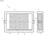
- Fig. 2 is a diagram showing a horizontal section view of the temperature control unit 1 according to the present embodiment and a side view from the side having the heat transfer medium discharge port 4.
- the heat transfer medium that has been introduced to the temperature control mechanism 3 through the heat transfer medium introduction port 2 is dispersed in the heat transfer medium dispersion area 10 before entering the metal fiber sheet 6, passes through the metal fiber sheet 6 and arrives at the heat transfer medium buffer area 11, and the heat transfer medium that has arrived at the heat transfer medium buffer area 11 is discharged to outside through the heat transfer medium discharge port 4.
- the heat transfer medium that has been introduced through the heat transfer medium introduction port 2 can be dispersed before entering into the metal fiber sheet 6.
- the heat transfer medium buffer area 11 between the metal fiber sheet 6 and the heat transfer medium discharge port 4 in the temperature control unit 1 the heat transfer medium can be made to flow well.
- the temperature-controlled surface can be prevented from being cooled or heated unevenly, thus allowing highly uniform temperature control.
- the temperature-controlled surface can be prevented from being cooled or heated unevenly.
- Fig. 3 is a diagram showing a horizontal section view of the temperature control unit 1a according to the present embodiment and a side view from the side having the heat transfer medium discharge port 4.
- the temperature control unit 1a illustrated in Fig. 3 differs from the temperature control unit 1 illustrated in Fig. 2 in that a temperature control mechanism 3a is provided instead of the temperature control mechanism 3.
- the temperature control mechanism 3a differs from the temperature control mechanism 3 illustrated in Fig. 2 in being provided with a housing 5a instead of the housing 5, being provided with a heat transfer medium dispersion area 10a instead of the heat transfer medium dispersion area 10, and being provided with a heat transfer medium buffer area 11a instead of the heat transfer medium buffer area 11.
- the housing 5a has a shape that continuously widens diagonally from the heat transfer medium introduction port 2 towards both end portions of the heat transfer medium introduction surface of the metal fiber sheet 6, thus forming a heat transfer medium dispersion area 10a having a substantially trapezoidal horizontal cross-section, and has a shape that is continuously angled so as to narrow down from both end portions of the heat transfer medium discharge surface of the metal fiber sheet 6 towards the heat transfer medium discharge port 4, thus forming a heat transfer medium buffer area 11a having a substantially trapezoidal cross-section.
- the heat transfer medium In the heat transfer medium dispersion area 10a, the heat transfer medium is guided towards the metal fiber sheet 6, and in the heat transfer medium buffer area 11a, the heat transfer medium flows well, thus allowing the heat transfer medium to be effectively dispersed.
- the temperature-controlled surface can be prevented from being cooled or heated unevenly, thus allowing highly uniform temperature control.
- the temperature control unit 1a is not limited to the above-mentioned configuration, and may include a mode in which a part of the area between the heat transfer medium introduction port 2 and the metal fiber sheet 6 widens diagonally, or a mode in which a part of the area between the metal fiber sheet 6 and the heat transfer medium discharge port 4 is angled.
- the temperature-controlled surface can be prevented from being cooled or heated unevenly by more effectively dispersing the heat transfer medium.
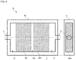
- Fig. 4 is a diagram showing a horizontal section view of a temperature control unit 1b according to the present embodiment and a side view from the side having the heat transfer medium discharge port 4.
- the temperature control unit 1b illustrated in Fig. 4 differs from the temperature control unit 1 illustrated in Fig. 2 in that a temperature control mechanism 3b is provided instead of the temperature control mechanism 3.
- the temperature control mechanism 3b differs from the temperature control mechanism 3 illustrated in Fig. 2 in being provided with a metal fiber sheet 6b1 and a metal fiber sheet 6b2 instead of the metal fiber sheet 6.
- the metal fiber sheet 6b1 which is a first metal fiber sheet, is arranged in the housing 5 on the side towards the heat transfer medium introduction port 2, and the metal fiber sheet 6b2, which is a second metal fiber sheet, is arranged in the housing 5 on the side towards the heat transfer medium discharge port 4.
- An intermediate area 12b is formed between the metal fiber sheet 6b1 and the metal fiber sheet 6b2.
- the flow rate of the heat transfer medium can be made uniform by forming the intermediate area 12b, which is a gap, between the metal fiber sheet 6b1 and the metal fiber sheet 6b2.
- the temperature-controlled surface can be prevented from being cooled or heated unevenly by making the flow rate of the heat transfer medium uniform.
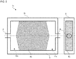
- Fig. 5 is a diagram showing a horizontal section view of a temperature control unit 1c according to the present embodiment and a side view from the side having the heat transfer medium discharge port 4.
- the temperature control unit 1c illustrated in Fig. 5 differs from the temperature control unit 1 illustrated in Fig. 2 in that a temperature control mechanism 3c is provided instead of the temperature control mechanism 3.
- the temperature control mechanism 3c differs from the temperature control mechanism 3 illustrated in Fig. 2 in being provided with a metal fiber sheet 6c instead of the metal fiber sheet 6, being provided with a heat transfer medium dispersion area 10c instead of the heat transfer medium dispersion area 10, and being provided with a heat transfer medium buffer area 11c instead of the heat transfer medium buffer area 11.
- the metal fiber sheet 6c has a shape that is long in a central portion sandwiched between the heat transfer medium introduction port 2 and the heat transfer medium discharge port 4, and that becomes short at both end portions of the heat transfer medium introduction surface and the heat transfer medium discharge surface.
- the heat transfer medium introduced from the heat transfer medium introduction port 2 has a long passage distance through the metal fiber sheet 6c in the central portion, and has a short passage distance through the metal fiber sheet 6c at both end portions, thus suppressing the flow rate of the heat transfer medium at the central portion to which the heat transfer medium is introduced in a high flow rate state.
- the metal fiber sheet 6c illustrated in Fig. 5 has a shape in which the central portion is longer than both end portions, this is because the heat transfer medium introduction port 2 and the heat transfer medium discharge port 4 are provided in the central portion, thus causing the flow rate of the heat transfer medium to be high in the central portion.
- the portion that is made longer need not be limited to the central portion as long as the path of the heat transfer medium in the metal fiber sheet is made longer at a portion at which the flow rate of the heat transfer medium that is introduced is higher than that at other portions.
- heat transfer medium introduction ports 2 and heat transfer medium discharge ports 4 are provided at both end portions, and the flow rate of the heat transfer medium is higher at both end portions than at the central portion, then the shape is made longer at both end portions than at the central portion.
- the temperature-controlled surface can be prevented from being cooled or heated unevenly by making the flow rate of the heat transfer medium uniform by means of the shape of the metal fiber sheet.
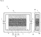
- Fig. 6 is a diagram showing a horizontal section view of a temperature control unit 1d according to the present embodiment and a side view from the side having the heat transfer medium discharge port 4.
- the temperature control unit 1d illustrated in Fig. 6 differs from the temperature control unit 1 illustrated in Fig. 2 in that a temperature control mechanism 3d is provided instead of the temperature control mechanism 3.
- the temperature control mechanism 3d differs from the temperature control mechanism 3 illustrated in Fig. 2 in being provided with a metal fiber sheet 6d instead of the metal fiber sheet 6.
- the metal fiber sheet 6d is provided with a fiber-concentrated area 6d1, in which the metal fibers are densely arranged, and a fiber-unconcentrated area 6d2 and a fiber-unconcentrated area 6d3, in which the metal fibers are more sparsely arranged than those in the fiber-concentrated area 6d1.
- the fiber-concentrated area 6d1 is arranged to be in a central portion sandwiched between the heat transfer medium introduction port 2 and the heat transfer medium discharge port 4, and the fiber-unconcentrated area 6d2 and the fiber-unconcentrated area 6d3 are arranged to be at the respective end portions.
- the heat transfer medium introduced from the heat transfer medium introduction port 2 passes through the fiber-concentrated area 6d1 in the central portion and passes through the fiber-unconcentrated area 6d2 or the fiber-unconcentrated area 6d3 at both end portions, thus suppressing the flow rate of the heat transfer medium more in the central portion, at which the flow rate is high at the time of introduction, than at both end portions.
- the metal fiber sheet 6d can be formed by partially stacking and pressing multiple metal fiber sheets.
- the metal fiber sheet 6d can be formed by pressing a larger number of stacked metal fiber sheets in the fiber-concentrated area 6d1, in which the metal fibers are densely arranged, than in the fiber-unconcentrated area 6d2 and the fiber-unconcentrated area 6d3.
- the temperature-controlled surface can be prevented from being cooled or heated unevenly by making the flow rate of the heat transfer medium uniform by means of the fiber density of the metal fiber sheet.
- Fig. 7 is a diagram showing a horizontal section view of a temperature control unit 1e according to the present embodiment and a side view from the side having the heat transfer medium discharge port 4.
- the temperature control unit 1e illustrated in Fig. 7 differs from the temperature control unit 1 illustrated in Fig. 2 in that a temperature control mechanism 3e is provided instead of the temperature control mechanism 3.
- the temperature control mechanism 3e differs from the temperature control mechanism 3 illustrated in Fig. 2 in being provided with a metal fiber sheet 6e instead of the metal fiber sheet 6.
- the metal fiber sheet 6e is provided with a heat transfer medium flow passage 13e formed by continuously removing a portion of the metal fiber sheet 6.
- the heat transfer medium flow passage 13e is formed from flow passages in a direction from the heat transfer medium introduction port 2 to the heat transfer medium discharge port 4, and flow passages in a direction perpendicular thereto.
- the metal fiber sheet 6e having such a configuration also suppresses differences between the flow rate in the central portion and at both end portions, thus allowing the flow rate of the heat transfer medium to be made uniform.
- the heat transfer medium flow passage 13e has a meandering shape due to the metal fiber sheet 6e, a portion of which is removed.
- the temperature-controlled surface can be prevented from being cooled or heated unevenly by making the flow rate of the heat transfer medium uniform by removing a portion of the metal fiber sheet to form a meandering heat transfer medium flow passage.
- Fig. 8 is a diagram showing a horizontal section view of a temperature control unit 1f according to the present embodiment and a side view from the side having the heat transfer medium discharge port 4.
- the temperature control unit 1f illustrated in Fig. 8 differs from the temperature control unit 1 illustrated in Fig. 2 in that a temperature control mechanism 3f is provided instead of the temperature control mechanism 3.
- the temperature control mechanism 3f differs from the temperature control mechanism 3 illustrated in Fig. 2 in being provided with a housing 5f instead of the housing 5, and being provided with a metal fiber sheet 6f instead of the metal fiber sheet 6.
- the housing 5f has a structure 9f1 and a structure 9f2 added to the housing 5.
- the structure 9f1 and the structure 9f2 are provided, respectively, on both end portions of the heat transfer medium introduction surface and the heat transfer medium discharge surface, and make the flow rate of the heat transfer medium higher by narrowing the flow passage of the heat transfer medium at both end portions.
- the housing 5f having such a configuration also suppresses differences between the flow rate in the central portion and at both end portions, thus allowing the flow rate of the heat transfer medium to be made uniform.
- the temperature control mechanism 3f illustrated in Fig. 8 is better at suppressing pressure loss of the heat transfer medium than the temperature control mechanism 3d illustrated in Fig. 6 is.
- the temperature-controlled surface can be prevented from being cooled or heated unevenly by making the flow rate of the heat transfer medium uniform by arranging structures at both sides of the housing.
- Fig. 9 is a diagram showing a horizontal section view of a temperature control unit 1g according to the present embodiment and a side view from the side having the heat transfer medium discharge port 4.
- the temperature control unit 1g illustrated in Fig. 9 differs from the temperature control unit 1 illustrated in Fig. 2 in that a temperature control mechanism 3g is provided instead of the temperature control mechanism 3.
- the temperature control mechanism 3g differs from the temperature control mechanism 3 illustrated in Fig. 2 in being provided with a housing 5g instead of the housing 5, and being provided with a metal fiber sheet 6g instead of the metal fiber sheet 6.
- the housing 5g has structures 9g1 and structures 9g2 added to the housing 5.
- a meandering flow passage is formed by the structures 9g1 and the structures 9g2, which block parts of the heat transfer medium flow passage.
- multiple structures 9g1 and structures 9g2 are provided on either of the end portions of the heat transfer medium introduction surface and the heat transfer medium discharge surface.
- the multiple structures 9g1 are provided so as to be in contact with either one of the end portions of the heat transfer medium introduction surface and the heat transfer medium discharge surface, and the multiple structures 9g2 are provided so as to be in contact with the other of the end portions of the heat transfer medium introduction surface and the heat transfer medium discharge surface.
- the multiple structures 9g1 and the multiple structures 9g2 are provided on surfaces that face each other in the housing 5g.
- the structures 9g1 and the structures 9g2 are arranged in alternating fashion.
- the housing 5g having such a configuration also suppresses differences between the flow rate in the central portion and at both end portions, thus allowing the flow rate of the heat transfer medium to be made uniform.
- the metal fiber sheet 6g can be formed by hollowing out a portion of the metal fiber sheet 6.
- the metal fiber sheet 6 can be hollowed out by using a hollowing mold, or by laser ablation.
- the mechanical strength of the metal fiber sheet 6g is preferably improved by sintering the housing 5g in which the metal fiber sheet 6g has been fitted, then adhering the metal fiber sheet 6g to the multiple structures 9g1 and structures 9g2 with epoxy or the like to fill the gaps therebetween.
- the temperature-controlled surface can be prevented from being cooled or heated unevenly by making the flow rate of the heat transfer medium uniform by arranging structures in alternating fashion on both sides of the housing to form the heat transfer medium flow passage.
- Embodiments 1 to 8 described above modes mainly characterized by the horizontal cross-section and the side surfaces of the temperature control unit were explained.
- the present invention is not limited thereto.
- Fig. 10(A) to 10(E) are diagrams illustrating, as temperature control units according to the present embodiment, first to fifth modified examples of cross-sections at A-A on the top surface of the temperature control unit illustrated in Fig. 1 .
- a sealing member (not illustrated) is provided between the housing and the heat exchange plate configured to provide a seal therebetween.
- a temperature control unit 1h which is the first modified example illustrated in Fig. 10(A) , has a heat transfer medium introduction port 2h, a temperature control mechanism 3h, and a heat transfer medium discharge port 4h.
- the temperature control mechanism 3h is provided with a metal fiber sheet 6, a housing 5h configured to house the metal fiber sheet 6, and a heat exchange plate 7 provided so that one main surface is exposed to the outer side of the temperature control mechanism 3h and the rear surface of the one main surface contacts the metal fiber sheet 6, thereby exchanging heat between the metal fiber sheet 6 and outside.
- the heat transfer medium introduced from the heat transfer medium introduction port 2h passes through the temperature control mechanism 3h and is discharged from the heat transfer medium discharge port 4h.
- the heat transfer medium introduction port 2h and the heat transfer medium discharge port 4h are expanded towards the heat exchange plate 7 in comparison with the temperature control unit 1 illustrated in Fig. 1 .
- the flow of the heat transfer medium is not hindered at the time of introduction and at the time of discharge.
- the cross-sectional areas of the dispersion area and the buffer area are made larger.
- the housing 5h differs from the housing 5 by having a shape in which the heat transfer medium introduction port 2h and the heat transfer medium discharge port 4h can be mounted.
- the heat transfer medium can be dispersed over a wider area than in the temperature control unit 1 illustrated in Fig. 1 , thereby improving the uniformity of the temperature of the heat transfer medium and allowing more highly uniform temperature control.
- a temperature control unit 1i which is the second modified example illustrated in Fig. 10(B) , has a heat transfer medium introduction port 2i, a temperature control mechanism 3i, and a heat transfer medium discharge port 4i.
- the temperature control mechanism 3i is provided with a metal fiber sheet 6, a housing 5i configured to house the metal fiber sheet 6, and a heat exchange plate 7 provided so that one main surface is exposed to the outer side of the temperature control mechanism 3i and the rear surface of the one main surface contacts the metal fiber sheet 6, thereby exchanging heat between the metal fiber sheet 6 and outside.
- the heat transfer medium introduced from the heat transfer medium introduction port 2i passes through the temperature control mechanism 3i and is discharged from the heat transfer medium discharge port 4i.
- the flow of the heat transfer medium is not hindered from the heat transfer medium introduction port 2i to the metal fiber sheet 6, and from the metal fiber sheet 6 to the heat transfer medium discharge port 4i.
- the housing 5i differs from the housing 5 by having a shape in which the flow of the heat transfer medium is not hindered from the heat transfer medium introduction port 2i to the metal fiber sheet 6, and from the metal fiber sheet 6 to the heat transfer medium discharge port 4i.
- a temperature control unit 1j which is the third modified example illustrated in Fig. 10(C) , has a heat transfer medium introduction port 2j, a temperature control mechanism 3j, and a heat transfer medium discharge port 4j.
- the temperature control mechanism 3j is provided with a metal fiber sheet 6, a housing 5j configured to house the metal fiber sheet 6, and a heat exchange plate 7j provided so that one main surface is exposed to the outer side of the temperature control mechanism 3j and the rear surface of the one main surface contacts the metal fiber sheet 6, thereby exchanging heat between the metal fiber sheet 6 and outside.
- the heat transfer medium introduced from the heat transfer medium introduction port 2j passes through the temperature control mechanism 3j and is discharged from the heat transfer medium discharge port 4j.
- the flow of the heat transfer medium is narrowed in a stepwise manner from the heat transfer medium introduction port 2j to the metal fiber sheet 6, and from the metal fiber sheet 6 to the heat transfer medium discharge port 4j.
- the housing 5j has a shape similar to that of the housing 5h illustrated in Fig. 10(A) .
- the heat exchange plate 7j differs from the heat exchange plate 7 by having a shape in which the heat transfer medium flow passage is narrowed in a stepwise manner.
- the introduction of the heat transfer medium into the flow passage can be made more uniform than in the temperature control unit 1 illustrated in Fig. 1 .
- a temperature control unit 1k which is the fourth modified example illustrated in Fig. 10(D) , has a heat transfer medium introduction port 2k, a temperature control mechanism 3k, and a heat transfer medium discharge port 4k.
- the temperature control mechanism 3k is provided with a metal fiber sheet 6k, a housing 5k configured to house the metal fiber sheet 6k, and a heat exchange plate 7 provided so that one main surface is exposed to the outer side of the temperature control mechanism 3k and the rear surface of the one main surface contacts the metal fiber sheet 6k, thereby exchanging heat between the metal fiber sheet 6k and outside.
- the heat transfer medium introduced from the heat transfer medium introduction port 2k passes through the temperature control mechanism 3k and is discharged from the heat transfer medium discharge port 4k.
- the heat transfer medium introduced from the heat transfer medium introduction port 2k is quickly dispersed in the dispersion area.
- the metal fiber sheet 6k is formed to be thicker than the metal fiber sheet 6.
- the housing 5k differs from the housing 5 by having a shape in which the heat transfer medium introduction port 2k and the heat transfer medium discharge port 4k can be mounted, and in which the metal fiber sheet 6k can be housed.
- the heat transfer medium can be more quickly dispersed in the dispersion area than in the temperature control unit 1 illustrated in Fig. 1 .
- a temperature control unit 11 which is the fifth modified example illustrated in Fig. 10(E) , has a heat transfer medium introduction port 21, a temperature control mechanism 31, and a heat transfer medium discharge port 41.
- the temperature control mechanism 3I is provided with a metal fiber sheet 6, a housing 5I configured to house the metal fiber sheet 6, and a heat exchange plate 7I provided so that one main surface is exposed to the outer side of the temperature control mechanism 3I and the rear surface of the one main surface contacts the metal fiber sheet 6, thereby exchanging heat between the metal fiber sheet 6 and outside.
- the heat transfer medium introduced from the heat transfer medium introduction port 2I passes through the temperature control mechanism 3I and is discharged from the heat transfer medium discharge port 41.
- the flow of the heat transfer medium is narrowed in a stepwise manner from the heat transfer medium introduction port 2I to the metal fiber sheet 6, and from the metal fiber sheet 6 to the heat transfer medium discharge port 41.
- the housing 5I differs from the housing 5k by having a shape in which the flow of the heat transfer medium is narrowed in a stepwise manner.
- the heat exchange plate 7I has a shape in which the flow passage of the heat transfer medium is narrowed in a stepwise manner, and has a cross-sectional shape similar to that of the heat exchange plate 7j.
- the heat transfer medium can be more quickly dispersed in the dispersion area and the introduction of the heat transfer medium into the flow passage can be made more uniform than in the temperature control unit 1 illustrated in Fig. 1 .
- the heat transfer medium introduction port and the heat transfer medium discharge port are installed in the temperature control mechanism from a horizontal direction.
- the present invention is not limited thereto.
- Fig. 11(A) and 11(B) are diagrams illustrating, as temperature control units according to the present embodiment, configurations in which the heat transfer medium introduction port and the heat transfer medium discharge port are installed in the temperature control unit from a vertical direction.
- a temperature control unit 1m illustrated in Fig. 11(A) has a heat transfer medium introduction port 2m, a temperature control mechanism 3m, and a heat transfer medium discharge port 4m.
- the temperature control mechanism 3m is provided with a metal fiber sheet 6, a housing 5m configured to house the metal fiber sheet 6, and a heat exchange plate 7m provided so that one main surface is exposed to the outer side of the temperature control mechanism 3m and the rear surface of the one main surface contacts the metal fiber sheet 6, thereby exchanging heat between the metal fiber sheet 6 and outside.
- the heat transfer medium introduced from the heat transfer medium introduction port 2m passes through the temperature control mechanism 3m and is discharged from the heat transfer medium discharge port 4m.
- the heat transfer medium introduction port 2m and the heat transfer medium discharge port 4m which penetrate through the heat exchange plate 7m, are installed in the temperature control mechanism 3m from a vertical direction.
- the housing 5m differs from the housing 5 in that openings are not provided in the side surfaces.
- the heat exchange plate 7m differs from the heat exchange plate 7 in that openings are provided configured to arrange the heat transfer medium introduction port 2m and the heat transfer medium discharge port 4m.
- a temperature control unit 1n illustrated in Fig. 11(B) has a heat transfer medium introduction port 2n, a temperature control mechanism 3n, and a heat transfer medium discharge port 4n.
- the temperature control mechanism 3n is provided with a metal fiber sheet 6, a housing 5n configured to house the metal fiber sheet 6, and a heat exchange plate 7 provided so that one main surface is exposed to the outer side of the temperature control mechanism 3n and the rear surface of the one main surface contacts the metal fiber sheet 6, thereby exchanging heat between the metal fiber sheet 6 and outside.
- the heat transfer medium introduced from the heat transfer medium introduction port 2n passes through the temperature control mechanism 3n and is discharged from the heat transfer medium discharge port 4n.
- the heat transfer medium introduction port 2n and the heat transfer medium discharge port 4n are installed in the temperature control mechanism 3n from a vertical direction by penetrating through the bottom surface of the housing 5n.
- the housing 5n differs from the housing 5 in that openings are provided in the bottom surface rather than in the side surfaces.
- the heat transfer medium may be introduced from a vertical direction.
- Fig. 11(A) illustrates a configuration in which the heat transfer medium is introduced to the temperature control mechanism from above and is discharged upward.
- Fig. 11(B) illustrates a configuration in which the heat transfer medium is introduced to the temperature control mechanism from below and is discharged downward.
- the present invention is not limited thereto, and may be configured so that the heat transfer medium is introduced to the temperature control mechanism from above and discharged downward, or configured so that the heat transfer medium is introduced from below and discharged upward.
- thermocontrol units according to Embodiments 1 to 9 above are provided with metal fiber sheets, as an alternative thereto, a porous metal may be provided.
- Metal fiber sheets and porous metals will be referred to collectively as porous metal bodies.
- metal fiber sheets include metal fiber nonwoven fabrics, metal fiber woven fabrics, and metal meshes.
- the heat exchange plates include temperature-controlled surfaces.
- a plate-shaped portion that does not perform heat exchange may be provided instead of the heat exchange plate, and the temperature-controlled surface may be included on the housing side.
- the heat exchange plate may include a temperature-controlled surface and the housing may include a temperature-controlled surface, in which case temperature-controlled surfaces are formed on both surfaces of the temperature control unit.
- the temperature control unit of the present invention does not need to be provided with a plate-shaped member.
- a plate-shaped member if one or more main surfaces of the housing are exposed to the outer side of the temperature control mechanism and the inner surfaces of those main surfaces contact the metal porous body, then the portions of the housing including those main surfaces function so as to exchange heat between the porous metal body and outside.
- the configuration of Embodiment 2 and the configuration of Embodiment 3 may be combined, the configuration of Embodiment 2 and the configuration of Embodiment 4 may be combined, and the configuration of Embodiment 2, the configuration of Embodiment 3, and the configuration of Embodiment 4 may be combined.
- Embodiment 9 can be favorably combined with the configurations of the other embodiments.
Landscapes
- Engineering & Computer Science (AREA)
- Microelectronics & Electronic Packaging (AREA)
- Physics & Mathematics (AREA)
- Thermal Sciences (AREA)
- Nonwoven Fabrics (AREA)
- Cooling Or The Like Of Semiconductors Or Solid State Devices (AREA)
- Cooling Or The Like Of Electrical Apparatus (AREA)
- Heat Treatment Of Strip Materials And Filament Materials (AREA)
Abstract
Description
- The present invention relates to a temperature control unit.
- Generally, when the power used in an electrical device increases, the amount of heat that is generated increases and the temperature of the electrical device becomes high, causing malfunctions, breakdowns, and the like.
- Therefore, electrical devices are often provided with cooling members for cooling and radiating away the generated heat.
- As one example of conventional art relating to such cooling members,
-
Patent Document 1 discloses a cooling member that has excellent cooling effects, that can easily be made compact and thin, and that allows localized cooling. The cooling member has a metal fiber sheet comprising metal fibers, and a cooling mechanism configured to cool the metal fiber sheet, wherein the cooling mechanism is provided with a housing configured to house the metal fiber sheet and a refrigerant-introducing means configured to introduce a refrigerant into the housing. - Patent Document 1:
JP 2019-9433 A - However, in
Patent Document 1, which is an example of the above-mentioned conventional art, there is a possibility that uneven cooling will occur in the case in which the dispersiveness of the refrigerant in the housing is low. - Additionally, the same can be said for the case in which the temperature in the housing is to be raised. There is a possibility that uneven heating will occur in the case in which the dispersiveness of a heating medium in the housing is low.
- That is, if the dispersiveness of a heat transfer medium in a housing is low, then there is a possibility that the temperature control will be uneven, and if the temperature control becomes uneven, then it is difficult to achieve uniform temperature control.
- The present invention was developed in consideration of the above, and an objective of the invention is to obtain a temperature control unit capable of highly uniform temperature control.
- The present invention, which solves the above-mentioned problem and achieves the objective, is a temperature control unit comprising: a heat transfer medium introduction port configured to introduce a heat transfer medium from outside; a temperature control mechanism through which the heat transfer medium from the heat transfer medium introduction port passes; and a heat transfer medium discharge port configured to discharge the heat transfer medium from the temperature control mechanism to outside, wherein: the temperature control mechanism comprises a porous metal body; and a housing configured to house the porous metal body; at least one main surface of the housing is exposed to an outer side of the temperature control mechanism, and an inner side of the main surface contacts the porous metal body, thereby exchanging heat between the porous metal body and outside; and a heat transfer medium dispersion area is provided between the heat transfer medium introduction port and the porous metal body.
- In the temperature control unit of the present invention having the above-mentioned configuration, a heat transfer medium buffer area is preferably provided between the porous metal body and the heat transfer medium discharge port.
- In the temperature control unit of the present invention having the above-mentioned configuration, the porous metal body is preferably a metal fiber sheet configured to include metal fibers.
- In the temperature control unit of the present invention having the above-mentioned configuration, the heat transfer medium dispersion area preferably has a shape that is continuously angled so as to widen out from the heat transfer medium introduction port towards both end portions of a heat transfer medium introduction surface of the porous metal body; and the heat transfer medium buffer area preferably has a shape that is continuously angled so as to narrow down from both end portions of a heat transfer medium discharge surface of the metal fiber sheet towards the heat transfer medium discharge port.
- In the temperature control unit of the present invention having the above-mentioned configuration, the metal fiber sheet preferably comprises: a first metal fiber sheet arranged on the heat transfer medium introduction port side; and a second metal fiber sheet arranged on the heat transfer medium discharge port side, and a gap is formed between the first metal fiber sheet and the second metal fiber sheet.
- In the temperature control unit of the present invention having the above-mentioned configuration, the metal fiber sheet preferably has a shape such that a passage for the heat transfer medium becomes longer in a portion at which the flow rate of the heat transfer medium becomes higher.
- In the temperature control unit of the present invention having the above-mentioned configuration, the metal fiber sheet is preferably configured such that the metal fibers are densely arranged in a portion at which the flow rate of the heat transfer medium becomes higher.
- In the temperature control unit of the present invention having the above-mentioned configuration, part of the metal fiber sheet is preferably removed to form a flow passage with a meandering shape.
- In the temperature control unit of the present invention having the above-mentioned configuration, the housing is preferably configured such that a flow passage for the heat transfer medium becomes narrow in a portion at which the flow rate of the heat transfer medium becomes lower.
- In the temperature control unit of the present invention having the above-mentioned configuration, the housing is preferably configured such that a structure blocks part of a flow passage for the heat transfer medium, thereby forming a meandering flow passage.
- According to the present invention, a temperature control unit capable of highly uniform temperature control can be obtained.
-
-
Fig. 1 is a diagram showing a top view of a temperature control unit according toEmbodiment 1 and a section view along A-A in the top view. -
Fig. 2 is a diagram showing a horizontal section view of the temperature control unit according toEmbodiment 1 and a side view from a side having a heat transfer medium discharge port. -
Fig. 3 is a diagram showing a horizontal section view of a temperature control unit according toEmbodiment 2 and a side view from a side having a heat transfer medium discharge port. -
Fig. 4 is a diagram showing a horizontal section view of a temperature control unit according toEmbodiment 3 and a side view from a side having a heat transfer medium discharge port. -
Fig. 5 is a diagram showing a horizontal section view of a temperature control unit according toEmbodiment 4 and a side view from a side having a heat transfer medium discharge port. -
Fig. 6 is a diagram showing a horizontal section view of a temperature control unit according toEmbodiment 5 and a side view from a side having a heat transfer medium discharge port. -
Fig. 7 is a diagram showing a horizontal section view of a temperature control unit according toEmbodiment 6 and a side view from a side having a heat transfer medium discharge port. -
Fig. 8 is a diagram showing a horizontal section view of a temperature control unit according toEmbodiment 7 and a side view from a side having a heat transfer medium discharge port. -
Fig. 9 is a diagram showing a horizontal section view of a temperature control unit according toEmbodiment 8 and a side view from a side having a heat transfer medium discharge port. -
Fig. 10 is a diagram showing, as temperature control units according to Embodiment 9, first to fifth modified examples of the section view along A-A in the top view shown inFig. 1 . -
Fig. 11 is a diagram showing, as temperature control units according to Embodiment 9, configurations in which a heat transfer medium introduction port and a heat transfer medium discharge port are installed in a temperature control mechanism from a vertical direction. - Embodiments of the present invention will be described below with reference to the drawings.
- However, the present invention should not be construed in a limiting manner based on the descriptions of the embodiments below.
- In the descriptions below, features that are the same will be denoted by the same reference numbers.
- First, the terminology to be used in the description below will be defined.
- "Metal fibers" refers to fibers in which the main component is a metal. For example, "copper fibers" refers to fibers in which the main component is copper.
- Additionally, in the case in which the main component is a metal, a certain amount of components other than said metal, such as impurities that are unavoidably contained, may be included, as long as the effects of the present invention are not compromised.
- Additionally, "thermal conductivity (W/(m·K))" is a value as measured by the laser flash method (for example, by using a "TC7000 series" laser flash thermal constant measuring device manufactured by Ulvac Riko, Inc.)
- Additionally, "average fiber diameter" refers to the arithmetic mean of area-based diameters derived by computing the cross-sectional areas perpendicular to the lengthwise direction of the metal fibers based on the perpendicular cross-sections at multiple locations in a metal fiber sheet imaged by a microscope, and computing the diameters of perfect circles having the same areas as said cross-sectional areas.
- The multiple locations may, for example, be twenty locations.
- Additionally, "average fiber length" refers to the arithmetic mean of measured values of the lengths of fibers in the lengthwise direction for multiple fibers randomly selected in a microscope image.
- If the fibers are not straight, then the lengths are the lengths of curves along the fibers.
- The multiple fibers may, for example, be twenty fibers.
- Additionally, "fill rate" refers to the proportion of the volume of a fiber sheet occupied by the fiber portions, and is computed from the basis weight and thickness of the fiber sheet, and the true density of the fibers, by means of the equation below.
- If the fiber sheet includes multiple types of fibers, then the fill rate can be computed by employing a true density value reflecting the compositional ratio of the fibers.

- "Thickness of the sheet" refers, for example, to the arithmetic mean in the case in which the metal fiber sheet has been measured at measurement points by means of an air-based terminal drop-type film thickness gauge (for example, "Digimatic Indicator ID-C112X" manufactured by Mitutoyo Corp.).
- "Homogeneity" refers to a sheet comprising fibers having little variance, within the sheet, in the properties of the sheet, such as electrical properties, physical properties, and air permeability properties.
- As an indicator of homogeneity, it is possible to employ, for example, the coefficient of variation (CV value) of the basis weight, as defined by the JIS Z8101 standard, per square centimeter.
- "Void rate" refers to the proportion of the volume of a fiber sheet constituted by portions in which voids are present, and is computed from the basis weight and thickness of the fiber sheet, and the true density of the fibers, by means of the equation below.
- If the fiber sheet includes multiple types of fibers, then the void rate can be computed by employing a true density value reflecting the compositional ratio of the fibers.

- The heat transfer medium in the present invention may be a gas, or may be a liquid or the like, and the characteristics thereof are not limited.
- That is, the heat transfer medium in the present invention may be a gas such as air, may be a liquid such as water or alcohol, or may be a fluorine-based compound such as a hydrofluorocarbon or a hydrofluoroether, or the like.
-
Fig. 1 is a diagram showing a top view of atemperature control unit 1 according to the present embodiment and a section view along A-A in the top view. - The
temperature control unit 1 shown inFig. 1 has a heat transfermedium introduction port 2, atemperature control mechanism 3, and a heat transfermedium discharge port 4. - The heat transfer
medium introduction port 2 is a port through which the heat transfer medium is introduced into thetemperature control mechanism 3 from outside. - The heat transfer
medium discharge port 4 is a port through which the heat transfer medium in thetemperature control mechanism 3 is discharged to outside. - A static mixer is preferably provided in the heat transfer
medium introduction port 2 in order to disperse the heat transfer medium that is introduced. - When a static mixer is provided in the heat transfer
medium introduction port 2, turbulence is created in the heat transfer medium that is introduced, allowing the amount of heat transferred to be increased. - The
temperature control mechanism 3 is provided with: ametal fiber sheet 6 configured to include metal fibers; ahousing 5 configured to house themetal fiber sheet 6; aheat exchange plate 7 provided so that one main surface is exposed to the outer side of thetemperature control mechanism 3 and the rear surface of the one main surface contacts themetal fiber sheet 6, thereby exchanging heat between themetal fiber sheet 6 and outside; and a sealingmember 8 configured to seal between thehousing 5 and theheat exchange plate 7. - The heat transfer medium introduced through the heat transfer
medium introduction port 2 passes through thetemperature control mechanism 3 and is discharged through the heat transfermedium discharge port 4. - The
metal fiber sheet 6 may be composed solely of metal fibers or may be configured to include components other than metal fibers. - Examples of the metal component in the metal fibers include copper, stainless steel, iron, aluminum, nickel, chromium, precious metals, and the like. Among the above, copper, stainless steel, and aluminum are preferable, and copper is particularly preferable.
- This is because copper fibers have an excellent balance of rigidity and plastic deformability.
- Examples of precious metals include gold, platinum, silver, palladium, rhodium, iridium, ruthenium, and osmium.
- Additionally, examples of components other than metal fibers that can be included in the
metal fiber sheet 6 include polyethylene terephthalate (PET), polyvinyl alcohol (PVA), polyolefins, polyvinyl chloride (PVC), polyamides, and acrylic, as well as organic substances that provide the fibrous matter with bonding properties and carrier properties. - In particular, in the case in which the
metal fiber sheet 6 is a nonwoven fabric having multiple metal fibers that are randomly entangled, the form sustainability and the functionality at the time of production of themetal fiber sheet 6 can be aided or improved by including one or more of these organic substances. - In the
metal fiber sheet 6, multiple metal fibers that are adjacent to each other are preferably bonded together. - That is, in the
metal fiber sheet 6, multiple metal fibers are preferably physically fixed to form bonded portions between the multiple metal fibers. - In the
metal fiber sheet 6, the multiple metal fibers may be directly fixed or indirectly fixed at the bonded portions. However, gaps should preferably be formed between at least some of the multiple metal fibers constituting themetal fiber sheet 6. - This is because, when such gaps are formed in the
metal fiber sheet 6, the heat transfer medium mentioned below can be more easily introduced into themetal fiber sheet 6. - Additionally, at these bonded portions, the multiple metal fibers are preferably sintered because this stabilizes the thermal conductivity and homogeneity of the
metal fiber sheet 6. - The gaps formed between the multiple metal fibers may be formed by entanglement of the metal fibers.
- The void rate in the
metal fiber sheet 6 is preferably at least 5% and at most 99%, more preferably at least 10% and at most 98%. - Additionally, the thermal conductivity of the metal fiber sheet is preferably at least 5 W/(m·K).
- Additionally, the
metal fiber sheet 6 need only be a sheet-shaped structure, and may be a nonwoven fabric having multiple metal fibers that are randomly entangled, or may be a woven fabric or a mesh material having regularity. - Additionally, the surface of the
metal fiber sheet 6 may be flat, or may be made bumpy by performing a corrugation process. - The basis weight of the
metal fiber sheet 6 should preferably be at least 10 g/m2 and at most 1,000 g/m2. - By setting the basis weight of the
metal fiber sheet 6 to be at least 10 g/m2, cooling or heating effects can be increased, and by setting the basis weight of themetal fiber sheet 6 to be at most 1,000 g/m2, themetal fiber sheet 6 can be made light in weight. - If the average fiber diameter of the metal fibers in the
metal fiber sheet 6 is less than 1 µm, then the rigidity of the metal fibers becomes lower and clumps tend to form when producing themetal fiber sheet 6, causing the thermal conductivity and homogeneity of themetal fiber sheet 6 to become unstable. - However, if the average fiber diameter of the metal fibers in the
metal fiber sheet 6 exceeds 30 µm, then the rigidity of the metal fibers becomes excessively high and the metal fibers cannot easily become entangled. - For this reason, the average fiber diameter of the metal fibers in the
metal fiber sheet 6 should preferably be at least 1 µm and at most 30 µm, and particularly preferably at least 2 µm and at most 20 µm. - Additionally, if the
metal fiber sheet 6 is a nonwoven fabric in which multiple metal fibers are randomly entangled, then the average fiber length of the metal fibers in themetal fiber sheet 6 should preferably be at least 1 mm and at most 10 mm in order to stabilize the thermal conductivity and homogeneity of themetal fiber sheet 6. - Additionally, if the aspect ratio of the metal fibers in the
metal fiber sheet 6 is lower than 33, then the metal fibers cannot easily become entangled. - On the other hand, if the aspect ratio of the metal fibers in the
metal fiber sheet 6 is higher than 10,000, then the homogeneity of themetal fiber sheet 6 decreases. - For this reason, the aspect ratio of the metal fibers should preferably be at least 33 and at most 10,000.
- Additionally, if the fill rate of the
metal fiber sheet 6 is less than 2%, then pressure loss when introducing the heat transfer medium is suppressed, but the cooling effects or heating effects are lowered because the fiber amount becomes insufficient. - On the other hand, if the fill rate of the
metal fiber sheet 6 exceeds 65%, then pressure loss when introducing the heat transfer medium increases. - For this reason, the fill rate of the
metal fiber sheet 6 is preferably at least 2%, more preferably at least 4%, and particularly preferably at least 5%. Additionally, the fill rate is preferably at most 65%, and more preferably at most 60%. - Additionally, in order to increase the homogeneity of the
metal fiber sheet 6, the CV value, which is the basis weight variation coefficient, as defined by the JIS Z8101 standard, per square centimeter of themetal fiber sheet 6, should preferably be at most 10%. - The method for manufacturing the
metal fiber sheet 6 is not limited to a specific method. - The manufacturing method in the case in which the
metal fiber sheet 6 is a mesh material or a woven fabric may involve using a plain weave in which metal wires are crossed one wire at a time, or may involve using a twilled weave in which metal wires that are arranged vertically and metal wires that are arranged horizontally are crossed over each other two wires at a time. Alternatively, a Dutch weave, a plain Dutch weave, or a twilled Dutch weave may be used. - Alternatively, in the case in which the
metal fiber sheet 6 is a mesh material, metal wires may be welded in a crossed state without being woven. - An example of a manufacturing method for the case in which the
metal fiber sheet 6 is a nonwoven fabric is a method for forming sheets by means of a wet sheet-forming method. - In a wet sheet-forming method, a slurry in which metal fibers and the like are dispersed in an aqueous medium is used to perform wet sheet-forming by means of a sheet-forming machine.
- In this case, the slurry may contain an additive such as a filler, a dispersant, a thickener, a defoamer, a sheet strength reinforcer, a sizer, a coagulant, a colorant, and a fixative.
- Additionally, a wet sheet obtained by the wet sheet-forming method may be subjected to a fiber entanglement treatment step for entangling the multiple metal fibers with each other.
- An example of the fiber entanglement treatment step is a method of spraying one main surface of the wet sheet with a high-pressure water jet.
- According to this method, the metal fibers or fibers including metal fibers can be entangled over the entirety of the wet sheet.
- This wet sheet is subjected to a dryer step by hot-air blow-drying after the fiber entanglement treatment step.
- This dryer step is preferably performed in an inert gas atmosphere using a reduced-pressure sintering furnace.
- The sheet that has been subjected to the dryer step is cooled to ambient temperature, then rolled up.
- The sheet that is obtained after having undergone the fiber entanglement treatment step and the dryer step may be subjected to a pressing step before the multiple metal fibers are bonded.
- Due to the pressing step, excessively large voids existing between the multiple metal fibers can be reduced, thereby increasing the homogeneity.
- Additionally, by adjusting the pressure during the pressing step, the thickness of the
metal fiber sheet 6 can also be adjusted. - As mentioned above, the bonded portions between the multiple metal fibers are preferably sintered by means of a sintering step.
- Due to the sintering step, the multiple metal fibers can be reliably bonded, the multiple metal fibers are fixed together, the CV value of the basis weight of the
metal fiber sheet 6 is stabilized, and the homogeneity and the thermal conductivity of themetal fiber sheet 6 are stabilized. - Additionally, the
metal fiber sheet 6 that has undergone the sintering step is preferably further subjected to a pressing step. - By being further subjected to a pressing step after the sintering step, the homogeneity of the
metal fiber sheet 6 can be further increased and themetal fiber sheet 6 can be made thin. - Furthermore, due to the pressing step after the sintering step, the metal fibers move not only in the thickness direction, but also in the planar direction in the
metal fiber sheet 6. - As a result thereof, metal fibers are provided even in areas that were voids at the time of sintering, thereby improving the homogeneity of the
metal fiber sheet 6, and this state is maintained by the plastic deformability of the metal fibers. - As the manufacturing method for the case in which the
metal fiber sheet 6 is a nonwoven fabric, a dry method in which the sheet is compression molded may be used. - In the dry method, a web mainly composed of metal fibers is prepared by a method such as the carding method or the air-laid method, and this web is compression molded.
- During the compression molding, the multiple metal fibers may be impregnated with a binder to bind the multiple metal fibers to each other.
- Examples of the binder include organic binders such as acrylic adhesives and inorganic binders such as colloidal silica.
- The
housing 5 is a thermally insulated structure configured to house themetal fiber sheet 6. - Examples of the material of the
housing 5 include metals, ceramics, and resins. - Examples of metal materials include stainless steel, copper, and aluminum.
- Additionally, examples of ceramic materials include alumina, zirconia, barium titanate, silicon carbide, silicon nitride, and aluminum nitride.
- Additionally, examples of resin materials include polyacrylate resins, polyvinylpyrrolidone resins, polyester resins, polypropylene resins, fluororesins such as polytetrafluoroethylene, polyimide resins, polyamide resins, and polyparaphenylene benzobisoxazole resins.
- The
housing 5 is thermally insulated with rock wool or the like after having been formed from the above-mentioned materials. - The
heat exchange plate 7 is a member that includes a temperature-controlled surface on one main surface, such that the rear surface of this temperature-controlled surface contacts themetal fiber sheet 6, thus exchanging heat between this temperature-controlled surface and themetal fiber sheet 6. - The material of the
heat exchange plate 7 should preferably be a material with high thermal conductivity, and examples of materials with high thermal conductivity include stainless steel, copper, and aluminum. - Additionally, the sintering step is preferably performed with the
metal fiber sheet 6 on theheat exchange plate 7 in a state of contact therewith because this bonds themetal fiber sheet 6 with theheat exchange plate 7. - When the
metal fiber sheet 6 and theheat exchange plate 7 are bonded together, heat is more easily conducted between themetal fiber sheet 6 and theheat exchange plate 7. - The sintering step is preferably performed in an inert gas atmosphere using a reduced-pressure sintering furnace.
- The sealing
member 8 is a member formed from a joining material configured to join thehousing 5 to theheat exchange plate 7. - As such a joining material, a metal joining material or an organic joining material may be used.
- Examples of metal joining materials include silver brazing material, phosphorus-copper brazing material, solder, and copper foil.
- The metal joining material preferably has a thermal conductivity of at least 50 W/(m·K) and a thickness of at most 100 µm.
- Examples of organic joining materials include epoxy, urethane, silicone, and the like, which should be heat-curable.
- Since organic joining materials have low thermal conductivities of less than 1 W/(m·K), they should preferably be made thin for the purposes of thermal conductivity, and the thickness thereof should preferably be at most 20 µm.
- The sealing
material 8 is preferably used to join theheat exchange plate 7 to thehousing 5 by means of sintering or a heat-curing reaction in a state in which thehousing 5 is, for example, placed on a member obtained by bonding themetal fiber sheet 6 to theheat exchange plate 7. -
Fig. 2 is a diagram showing a horizontal section view of thetemperature control unit 1 according to the present embodiment and a side view from the side having the heat transfermedium discharge port 4. - In
Fig. 2 , the heat transfer medium that has been introduced to thetemperature control mechanism 3 through the heat transfermedium introduction port 2 is dispersed in the heat transfermedium dispersion area 10 before entering themetal fiber sheet 6, passes through themetal fiber sheet 6 and arrives at the heat transfermedium buffer area 11, and the heat transfer medium that has arrived at the heat transfermedium buffer area 11 is discharged to outside through the heat transfermedium discharge port 4. - As illustrated in
Fig. 2 , by providing the heat transfermedium dispersion area 10 between the heat transfermedium introduction port 2 and themetal fiber sheet 6 in thetemperature control unit 1, the heat transfer medium that has been introduced through the heat transfermedium introduction port 2 can be dispersed before entering into themetal fiber sheet 6. - Additionally, by providing the heat transfer
medium buffer area 11 between themetal fiber sheet 6 and the heat transfermedium discharge port 4 in thetemperature control unit 1, the heat transfer medium can be made to flow well. - Therefore, by providing the heat transfer
medium dispersion area 10 between the heat transfermedium introduction port 2 and themetal fiber sheet 6 inside thetemperature control unit 1, and providing the heat transfermedium buffer area 11 between themetal fiber sheet 6 and the heat transfermedium discharge port 4 in thetemperature control unit 1, the temperature-controlled surface can be prevented from being cooled or heated unevenly, thus allowing highly uniform temperature control. - As described above, according to the present embodiment, the temperature-controlled surface can be prevented from being cooled or heated unevenly.
- In the present embodiment, a mode in which uneven cooling or heating on the temperature-controlled surface can be prevented by effectively dispersing the heat transfer medium by the shape of the housing, thus allowing highly uniform temperature control, will be described.
-
Fig. 3 is a diagram showing a horizontal section view of the temperature control unit 1a according to the present embodiment and a side view from the side having the heat transfermedium discharge port 4. - The temperature control unit 1a illustrated in
Fig. 3 differs from thetemperature control unit 1 illustrated inFig. 2 in that a temperature control mechanism 3a is provided instead of thetemperature control mechanism 3. - The temperature control mechanism 3a differs from the
temperature control mechanism 3 illustrated inFig. 2 in being provided with ahousing 5a instead of thehousing 5, being provided with a heat transfermedium dispersion area 10a instead of the heat transfermedium dispersion area 10, and being provided with a heat transfermedium buffer area 11a instead of the heat transfermedium buffer area 11. - The
housing 5a has a shape that continuously widens diagonally from the heat transfermedium introduction port 2 towards both end portions of the heat transfer medium introduction surface of themetal fiber sheet 6, thus forming a heat transfermedium dispersion area 10a having a substantially trapezoidal horizontal cross-section, and has a shape that is continuously angled so as to narrow down from both end portions of the heat transfer medium discharge surface of themetal fiber sheet 6 towards the heat transfermedium discharge port 4, thus forming a heat transfermedium buffer area 11a having a substantially trapezoidal cross-section. - In the heat transfer
medium dispersion area 10a, the heat transfer medium is guided towards themetal fiber sheet 6, and in the heat transfermedium buffer area 11a, the heat transfer medium flows well, thus allowing the heat transfer medium to be effectively dispersed. - For this reason, the temperature-controlled surface can be prevented from being cooled or heated unevenly, thus allowing highly uniform temperature control.
- The temperature control unit 1a according to the present embodiment is not limited to the above-mentioned configuration, and may include a mode in which a part of the area between the heat transfer
medium introduction port 2 and themetal fiber sheet 6 widens diagonally, or a mode in which a part of the area between themetal fiber sheet 6 and the heat transfermedium discharge port 4 is angled. - As explained above, according to the present embodiment, the temperature-controlled surface can be prevented from being cooled or heated unevenly by more effectively dispersing the heat transfer medium.
- In the present embodiment, a mode in which uneven cooling or heating on the temperature-controlled surface can be prevented by adjusting the flow rate of the heat transfer medium by the arrangement of the metal fiber sheet, thus allowing highly uniform temperature control, will be described.
-
Fig. 4 is a diagram showing a horizontal section view of atemperature control unit 1b according to the present embodiment and a side view from the side having the heat transfermedium discharge port 4. - The
temperature control unit 1b illustrated inFig. 4 differs from thetemperature control unit 1 illustrated inFig. 2 in that atemperature control mechanism 3b is provided instead of thetemperature control mechanism 3. - The
temperature control mechanism 3b differs from thetemperature control mechanism 3 illustrated inFig. 2 in being provided with a metal fiber sheet 6b1 and a metal fiber sheet 6b2 instead of themetal fiber sheet 6. - The metal fiber sheet 6b1, which is a first metal fiber sheet, is arranged in the
housing 5 on the side towards the heat transfermedium introduction port 2, and the metal fiber sheet 6b2, which is a second metal fiber sheet, is arranged in thehousing 5 on the side towards the heat transfermedium discharge port 4. Anintermediate area 12b is formed between the metal fiber sheet 6b1 and the metal fiber sheet 6b2. - In the
temperature control mechanism 3b, the flow rate of the heat transfer medium can be made uniform by forming theintermediate area 12b, which is a gap, between the metal fiber sheet 6b1 and the metal fiber sheet 6b2. - As explained above, according to the present embodiment, the temperature-controlled surface can be prevented from being cooled or heated unevenly by making the flow rate of the heat transfer medium uniform.
- In the present embodiment, a mode in which uneven cooling or heating on the temperature-controlled surface can be prevented by making the flow rate of the heat transfer medium uniform by means of the shape of the metal fiber sheet, thus allowing highly uniform temperature control, will be described.
-
Fig. 5 is a diagram showing a horizontal section view of atemperature control unit 1c according to the present embodiment and a side view from the side having the heat transfermedium discharge port 4. - The
temperature control unit 1c illustrated inFig. 5 differs from thetemperature control unit 1 illustrated inFig. 2 in that atemperature control mechanism 3c is provided instead of thetemperature control mechanism 3. - The
temperature control mechanism 3c differs from thetemperature control mechanism 3 illustrated inFig. 2 in being provided with ametal fiber sheet 6c instead of themetal fiber sheet 6, being provided with a heat transfermedium dispersion area 10c instead of the heat transfermedium dispersion area 10, and being provided with a heat transfermedium buffer area 11c instead of the heat transfermedium buffer area 11. - The
metal fiber sheet 6c has a shape that is long in a central portion sandwiched between the heat transfermedium introduction port 2 and the heat transfermedium discharge port 4, and that becomes short at both end portions of the heat transfer medium introduction surface and the heat transfer medium discharge surface. - By providing the
metal fiber sheet 6c with such a shape, the heat transfer medium introduced from the heat transfermedium introduction port 2 has a long passage distance through themetal fiber sheet 6c in the central portion, and has a short passage distance through themetal fiber sheet 6c at both end portions, thus suppressing the flow rate of the heat transfer medium at the central portion to which the heat transfer medium is introduced in a high flow rate state. - For this reason, the difference between the flow rate of the heat transfer medium in the central portion and at both end portions is made small, thus allowing the flow rate of the heat transfer medium to be made uniform.
- Although the
metal fiber sheet 6c illustrated inFig. 5 has a shape in which the central portion is longer than both end portions, this is because the heat transfermedium introduction port 2 and the heat transfermedium discharge port 4 are provided in the central portion, thus causing the flow rate of the heat transfer medium to be high in the central portion. - The portion that is made longer need not be limited to the central portion as long as the path of the heat transfer medium in the metal fiber sheet is made longer at a portion at which the flow rate of the heat transfer medium that is introduced is higher than that at other portions.
- For example, if heat transfer
medium introduction ports 2 and heat transfermedium discharge ports 4 are provided at both end portions, and the flow rate of the heat transfer medium is higher at both end portions than at the central portion, then the shape is made longer at both end portions than at the central portion. - As explained above, according to the present embodiment, the temperature-controlled surface can be prevented from being cooled or heated unevenly by making the flow rate of the heat transfer medium uniform by means of the shape of the metal fiber sheet.
- In the present embodiment, a mode in which uneven cooling or heating on the temperature-controlled surface can be prevented by making the flow rate of the heat transfer medium uniform by adjusting the fiber density of the metal fiber sheet, thus allowing highly uniform temperature control, will be described.
-
Fig. 6 is a diagram showing a horizontal section view of a temperature control unit 1d according to the present embodiment and a side view from the side having the heat transfermedium discharge port 4. - The temperature control unit 1d illustrated in
Fig. 6 differs from thetemperature control unit 1 illustrated inFig. 2 in that atemperature control mechanism 3d is provided instead of thetemperature control mechanism 3. - The
temperature control mechanism 3d differs from thetemperature control mechanism 3 illustrated inFig. 2 in being provided with ametal fiber sheet 6d instead of themetal fiber sheet 6. - The
metal fiber sheet 6d is provided with a fiber-concentrated area 6d1, in which the metal fibers are densely arranged, and a fiber-unconcentrated area 6d2 and a fiber-unconcentrated area 6d3, in which the metal fibers are more sparsely arranged than those in the fiber-concentrated area 6d1. - The fiber-concentrated area 6d1 is arranged to be in a central portion sandwiched between the heat transfer
medium introduction port 2 and the heat transfermedium discharge port 4, and the fiber-unconcentrated area 6d2 and the fiber-unconcentrated area 6d3 are arranged to be at the respective end portions. - By configuring the
metal fiber sheet 6d in such a manner, the heat transfer medium introduced from the heat transfermedium introduction port 2 passes through the fiber-concentrated area 6d1 in the central portion and passes through the fiber-unconcentrated area 6d2 or the fiber-unconcentrated area 6d3 at both end portions, thus suppressing the flow rate of the heat transfer medium more in the central portion, at which the flow rate is high at the time of introduction, than at both end portions. - For this reason, the difference in flow rate is suppressed between the heat transfer medium in the central portion, at which the flow rate of the heat transfer medium is high, and in both end portions, at which the flow rate of the heat transfer medium is low, thus allowing the flow rate of the heat transfer medium to be made uniform.
- The
metal fiber sheet 6d can be formed by partially stacking and pressing multiple metal fiber sheets. - The
metal fiber sheet 6d can be formed by pressing a larger number of stacked metal fiber sheets in the fiber-concentrated area 6d1, in which the metal fibers are densely arranged, than in the fiber-unconcentrated area 6d2 and the fiber-unconcentrated area 6d3. - As explained above, according to the present embodiment, the temperature-controlled surface can be prevented from being cooled or heated unevenly by making the flow rate of the heat transfer medium uniform by means of the fiber density of the metal fiber sheet.
- In the present embodiment, a mode in which uneven cooling or heating on the temperature-controlled surface can be prevented by making the flow rate of the heat transfer medium uniform by removing a portion of the metal fiber sheet to form a flow passage for the heat transfer medium, thus allowing highly uniform temperature control, will be described.
-
Fig. 7 is a diagram showing a horizontal section view of atemperature control unit 1e according to the present embodiment and a side view from the side having the heat transfermedium discharge port 4. - The
temperature control unit 1e illustrated inFig. 7 differs from thetemperature control unit 1 illustrated inFig. 2 in that atemperature control mechanism 3e is provided instead of thetemperature control mechanism 3. - The
temperature control mechanism 3e differs from thetemperature control mechanism 3 illustrated inFig. 2 in being provided with ametal fiber sheet 6e instead of themetal fiber sheet 6. - The
metal fiber sheet 6e is provided with a heat transfermedium flow passage 13e formed by continuously removing a portion of themetal fiber sheet 6. - The heat transfer
medium flow passage 13e is formed from flow passages in a direction from the heat transfermedium introduction port 2 to the heat transfermedium discharge port 4, and flow passages in a direction perpendicular thereto. - The
metal fiber sheet 6e having such a configuration also suppresses differences between the flow rate in the central portion and at both end portions, thus allowing the flow rate of the heat transfer medium to be made uniform. - The heat transfer
medium flow passage 13e has a meandering shape due to themetal fiber sheet 6e, a portion of which is removed. - As explained above, according to the present embodiment, the temperature-controlled surface can be prevented from being cooled or heated unevenly by making the flow rate of the heat transfer medium uniform by removing a portion of the metal fiber sheet to form a meandering heat transfer medium flow passage.
- In the present embodiment, a mode in which uneven cooling or heating on the temperature-controlled surface can be prevented by making the flow rate of the heat transfer medium uniform by means of the shape of the housing of the temperature control mechanism, thus allowing highly uniform temperature control, will be described.
-
Fig. 8 is a diagram showing a horizontal section view of atemperature control unit 1f according to the present embodiment and a side view from the side having the heat transfermedium discharge port 4. - The
temperature control unit 1f illustrated inFig. 8 differs from thetemperature control unit 1 illustrated inFig. 2 in that atemperature control mechanism 3f is provided instead of thetemperature control mechanism 3. - The
temperature control mechanism 3f differs from thetemperature control mechanism 3 illustrated inFig. 2 in being provided with ahousing 5f instead of thehousing 5, and being provided with ametal fiber sheet 6f instead of themetal fiber sheet 6. - The
housing 5f has a structure 9f1 and a structure 9f2 added to thehousing 5. - In the
housing 5f, the structure 9f1 and the structure 9f2 are provided, respectively, on both end portions of the heat transfer medium introduction surface and the heat transfer medium discharge surface, and make the flow rate of the heat transfer medium higher by narrowing the flow passage of the heat transfer medium at both end portions. - The
housing 5f having such a configuration also suppresses differences between the flow rate in the central portion and at both end portions, thus allowing the flow rate of the heat transfer medium to be made uniform. - Additionally, the
temperature control mechanism 3f illustrated inFig. 8 is better at suppressing pressure loss of the heat transfer medium than thetemperature control mechanism 3d illustrated inFig. 6 is. - As explained above, according to the present embodiment, the temperature-controlled surface can be prevented from being cooled or heated unevenly by making the flow rate of the heat transfer medium uniform by arranging structures at both sides of the housing.
- In the present embodiment, a mode in which uneven cooling or heating on the temperature-controlled surface can be prevented by making the flow rate of the heat transfer medium uniform by providing the housing of the temperature control mechanism with structures different from those in
Embodiment 7, thus allowing highly uniform temperature control, will be described. -
Fig. 9 is a diagram showing a horizontal section view of atemperature control unit 1g according to the present embodiment and a side view from the side having the heat transfermedium discharge port 4. - The
temperature control unit 1g illustrated inFig. 9 differs from thetemperature control unit 1 illustrated inFig. 2 in that atemperature control mechanism 3g is provided instead of thetemperature control mechanism 3. - The
temperature control mechanism 3g differs from thetemperature control mechanism 3 illustrated inFig. 2 in being provided with ahousing 5g instead of thehousing 5, and being provided with ametal fiber sheet 6g instead of themetal fiber sheet 6. - The
housing 5g has structures 9g1 and structures 9g2 added to thehousing 5. - In the
housing 5g, a meandering flow passage is formed by the structures 9g1 and the structures 9g2, which block parts of the heat transfer medium flow passage. - In the
housing 5g illustrated inFig. 9 , multiple structures 9g1 and structures 9g2 are provided on either of the end portions of the heat transfer medium introduction surface and the heat transfer medium discharge surface. - The multiple structures 9g1 are provided so as to be in contact with either one of the end portions of the heat transfer medium introduction surface and the heat transfer medium discharge surface, and the multiple structures 9g2 are provided so as to be in contact with the other of the end portions of the heat transfer medium introduction surface and the heat transfer medium discharge surface.
- In other words, the multiple structures 9g1 and the multiple structures 9g2 are provided on surfaces that face each other in the
housing 5g. - The structures 9g1 and the structures 9g2 are arranged in alternating fashion.
- The
housing 5g having such a configuration also suppresses differences between the flow rate in the central portion and at both end portions, thus allowing the flow rate of the heat transfer medium to be made uniform. - The
metal fiber sheet 6g can be formed by hollowing out a portion of themetal fiber sheet 6. - The
metal fiber sheet 6 can be hollowed out by using a hollowing mold, or by laser ablation. - Furthermore, the mechanical strength of the
metal fiber sheet 6g is preferably improved by sintering thehousing 5g in which themetal fiber sheet 6g has been fitted, then adhering themetal fiber sheet 6g to the multiple structures 9g1 and structures 9g2 with epoxy or the like to fill the gaps therebetween. - As explained above, according to the present embodiment, the temperature-controlled surface can be prevented from being cooled or heated unevenly by making the flow rate of the heat transfer medium uniform by arranging structures in alternating fashion on both sides of the housing to form the heat transfer medium flow passage.
- In
Embodiments 1 to 8 described above, modes mainly characterized by the horizontal cross-section and the side surfaces of the temperature control unit were explained. However, the present invention is not limited thereto. -
Fig. 10(A) to 10(E) are diagrams illustrating, as temperature control units according to the present embodiment, first to fifth modified examples of cross-sections at A-A on the top surface of the temperature control unit illustrated inFig. 1 . - Additionally, in the present embodiment, a sealing member (not illustrated) is provided between the housing and the heat exchange plate configured to provide a seal therebetween.
- A
temperature control unit 1h, which is the first modified example illustrated inFig. 10(A) , has a heat transfermedium introduction port 2h, atemperature control mechanism 3h, and a heat transfermedium discharge port 4h. - The
temperature control mechanism 3h is provided with ametal fiber sheet 6, ahousing 5h configured to house themetal fiber sheet 6, and aheat exchange plate 7 provided so that one main surface is exposed to the outer side of thetemperature control mechanism 3h and the rear surface of the one main surface contacts themetal fiber sheet 6, thereby exchanging heat between themetal fiber sheet 6 and outside. - The heat transfer medium introduced from the heat transfer
medium introduction port 2h passes through thetemperature control mechanism 3h and is discharged from the heat transfermedium discharge port 4h. - In the
temperature control unit 1h illustrated inFig. 10(A) , the heat transfermedium introduction port 2h and the heat transfermedium discharge port 4h are expanded towards theheat exchange plate 7 in comparison with thetemperature control unit 1 illustrated inFig. 1 . Thus, the flow of the heat transfer medium is not hindered at the time of introduction and at the time of discharge. Furthermore, the cross-sectional areas of the dispersion area and the buffer area are made larger. - Additionally, the
housing 5h differs from thehousing 5 by having a shape in which the heat transfermedium introduction port 2h and the heat transfermedium discharge port 4h can be mounted. - By having such a configuration, the heat transfer medium can be dispersed over a wider area than in the
temperature control unit 1 illustrated inFig. 1 , thereby improving the uniformity of the temperature of the heat transfer medium and allowing more highly uniform temperature control. - A temperature control unit 1i, which is the second modified example illustrated in
Fig. 10(B) , has a heat transfer medium introduction port 2i, a temperature control mechanism 3i, and a heat transfer medium discharge port 4i. - The temperature control mechanism 3i is provided with a
metal fiber sheet 6, ahousing 5i configured to house themetal fiber sheet 6, and aheat exchange plate 7 provided so that one main surface is exposed to the outer side of the temperature control mechanism 3i and the rear surface of the one main surface contacts themetal fiber sheet 6, thereby exchanging heat between themetal fiber sheet 6 and outside. - The heat transfer medium introduced from the heat transfer medium introduction port 2i passes through the temperature control mechanism 3i and is discharged from the heat transfer medium discharge port 4i.
- In the temperature control unit 1i illustrated in
Fig. 10(B) , the flow of the heat transfer medium is not hindered from the heat transfer medium introduction port 2i to themetal fiber sheet 6, and from themetal fiber sheet 6 to the heat transfer medium discharge port 4i. - Additionally, the
housing 5i differs from thehousing 5 by having a shape in which the flow of the heat transfer medium is not hindered from the heat transfer medium introduction port 2i to themetal fiber sheet 6, and from themetal fiber sheet 6 to the heat transfer medium discharge port 4i. - By having such a configuration, pressure loss of the heat transfer medium can be better suppressed than in the
temperature control unit 1 illustrated inFig. 1 . - A
temperature control unit 1j, which is the third modified example illustrated inFig. 10(C) , has a heat transfermedium introduction port 2j, a temperature control mechanism 3j, and a heat transfer medium discharge port 4j. - The temperature control mechanism 3j is provided with a
metal fiber sheet 6, ahousing 5j configured to house themetal fiber sheet 6, and a heat exchange plate 7j provided so that one main surface is exposed to the outer side of the temperature control mechanism 3j and the rear surface of the one main surface contacts themetal fiber sheet 6, thereby exchanging heat between themetal fiber sheet 6 and outside. - The heat transfer medium introduced from the heat transfer
medium introduction port 2j passes through the temperature control mechanism 3j and is discharged from the heat transfer medium discharge port 4j. - In the
temperature control unit 1j illustrated inFig. 10(C) , the flow of the heat transfer medium is narrowed in a stepwise manner from the heat transfermedium introduction port 2j to themetal fiber sheet 6, and from themetal fiber sheet 6 to the heat transfer medium discharge port 4j. - The
housing 5j has a shape similar to that of thehousing 5h illustrated inFig. 10(A) . - Additionally, the heat exchange plate 7j differs from the
heat exchange plate 7 by having a shape in which the heat transfer medium flow passage is narrowed in a stepwise manner. - By having such a configuration, the introduction of the heat transfer medium into the flow passage can be made more uniform than in the
temperature control unit 1 illustrated inFig. 1 . - A
temperature control unit 1k, which is the fourth modified example illustrated inFig. 10(D) , has a heat transfermedium introduction port 2k, atemperature control mechanism 3k, and a heat transfermedium discharge port 4k. - The
temperature control mechanism 3k is provided with ametal fiber sheet 6k, ahousing 5k configured to house themetal fiber sheet 6k, and aheat exchange plate 7 provided so that one main surface is exposed to the outer side of thetemperature control mechanism 3k and the rear surface of the one main surface contacts themetal fiber sheet 6k, thereby exchanging heat between themetal fiber sheet 6k and outside. - The heat transfer medium introduced from the heat transfer
medium introduction port 2k passes through thetemperature control mechanism 3k and is discharged from the heat transfermedium discharge port 4k. - In the
temperature control unit 1k illustrated inFig. 10(D) , the heat transfer medium introduced from the heat transfermedium introduction port 2k is quickly dispersed in the dispersion area. - The
metal fiber sheet 6k is formed to be thicker than themetal fiber sheet 6. - Additionally, the
housing 5k differs from thehousing 5 by having a shape in which the heat transfermedium introduction port 2k and the heat transfermedium discharge port 4k can be mounted, and in which themetal fiber sheet 6k can be housed. - By having such a configuration, the heat transfer medium can be more quickly dispersed in the dispersion area than in the
temperature control unit 1 illustrated inFig. 1 . - A
temperature control unit 11, which is the fifth modified example illustrated inFig. 10(E) , has a heat transfermedium introduction port 21, atemperature control mechanism 31, and a heat transfermedium discharge port 41. - The temperature control mechanism 3I is provided with a
metal fiber sheet 6, a housing 5I configured to house themetal fiber sheet 6, and a heat exchange plate 7I provided so that one main surface is exposed to the outer side of the temperature control mechanism 3I and the rear surface of the one main surface contacts themetal fiber sheet 6, thereby exchanging heat between themetal fiber sheet 6 and outside. - The heat transfer medium introduced from the heat transfer medium introduction port 2I passes through the temperature control mechanism 3I and is discharged from the heat transfer
medium discharge port 41. - In the temperature control unit 1I illustrated in
Fig. 10(E) , the flow of the heat transfer medium is narrowed in a stepwise manner from the heat transfer medium introduction port 2I to themetal fiber sheet 6, and from themetal fiber sheet 6 to the heat transfermedium discharge port 41. - The housing 5I differs from the
housing 5k by having a shape in which the flow of the heat transfer medium is narrowed in a stepwise manner. - Additionally, the heat exchange plate 7I has a shape in which the flow passage of the heat transfer medium is narrowed in a stepwise manner, and has a cross-sectional shape similar to that of the heat exchange plate 7j.
- By having such a configuration, the heat transfer medium can be more quickly dispersed in the dispersion area and the introduction of the heat transfer medium into the flow passage can be made more uniform than in the
temperature control unit 1 illustrated inFig. 1 . - As described with reference to
Fig. 10 above, various cross-sectional shapes may be employed for the temperature control unit according to the present invention. - Additionally, with the above-mentioned configurations, the heat transfer medium introduction port and the heat transfer medium discharge port are installed in the temperature control mechanism from a horizontal direction. However, the present invention is not limited thereto.
-
Fig. 11(A) and 11(B) are diagrams illustrating, as temperature control units according to the present embodiment, configurations in which the heat transfer medium introduction port and the heat transfer medium discharge port are installed in the temperature control unit from a vertical direction. - A
temperature control unit 1m illustrated inFig. 11(A) has a heat transfermedium introduction port 2m, atemperature control mechanism 3m, and a heat transfermedium discharge port 4m. - The
temperature control mechanism 3m is provided with ametal fiber sheet 6, ahousing 5m configured to house themetal fiber sheet 6, and aheat exchange plate 7m provided so that one main surface is exposed to the outer side of thetemperature control mechanism 3m and the rear surface of the one main surface contacts themetal fiber sheet 6, thereby exchanging heat between themetal fiber sheet 6 and outside. - The heat transfer medium introduced from the heat transfer
medium introduction port 2m passes through thetemperature control mechanism 3m and is discharged from the heat transfermedium discharge port 4m. - In the
temperature control unit 1m illustrated inFig. 11(A) , the heat transfermedium introduction port 2m and the heat transfermedium discharge port 4m, which penetrate through theheat exchange plate 7m, are installed in thetemperature control mechanism 3m from a vertical direction. - The
housing 5m differs from thehousing 5 in that openings are not provided in the side surfaces. - Additionally, the
heat exchange plate 7m differs from theheat exchange plate 7 in that openings are provided configured to arrange the heat transfermedium introduction port 2m and the heat transfermedium discharge port 4m. - A
temperature control unit 1n illustrated inFig. 11(B) has a heat transfermedium introduction port 2n, atemperature control mechanism 3n, and a heat transfermedium discharge port 4n. - The
temperature control mechanism 3n is provided with ametal fiber sheet 6, ahousing 5n configured to house themetal fiber sheet 6, and aheat exchange plate 7 provided so that one main surface is exposed to the outer side of thetemperature control mechanism 3n and the rear surface of the one main surface contacts themetal fiber sheet 6, thereby exchanging heat between themetal fiber sheet 6 and outside. - The heat transfer medium introduced from the heat transfer
medium introduction port 2n passes through thetemperature control mechanism 3n and is discharged from the heat transfermedium discharge port 4n. - In the
temperature control unit 1n illustrated inFig. 11(B) , the heat transfermedium introduction port 2n and the heat transfermedium discharge port 4n are installed in thetemperature control mechanism 3n from a vertical direction by penetrating through the bottom surface of thehousing 5n. - The
housing 5n differs from thehousing 5 in that openings are provided in the bottom surface rather than in the side surfaces. - As described with reference to
Fig. 11 above, in the temperature control unit according to the present invention, the heat transfer medium may be introduced from a vertical direction. - Additionally,
Fig. 11(A) illustrates a configuration in which the heat transfer medium is introduced to the temperature control mechanism from above and is discharged upward. -
Fig. 11(B) illustrates a configuration in which the heat transfer medium is introduced to the temperature control mechanism from below and is discharged downward. However, the present invention is not limited thereto, and may be configured so that the heat transfer medium is introduced to the temperature control mechanism from above and discharged downward, or configured so that the heat transfer medium is introduced from below and discharged upward. - Although the temperature control units according to
Embodiments 1 to 9 above are provided with metal fiber sheets, as an alternative thereto, a porous metal may be provided. Metal fiber sheets and porous metals will be referred to collectively as porous metal bodies. - Additionally, metal fiber sheets include metal fiber nonwoven fabrics, metal fiber woven fabrics, and metal meshes.
- In the temperature control units according to
Embodiments 1 to 9 above, the heat exchange plates include temperature-controlled surfaces. However, the present invention is not limited thereto. A plate-shaped portion that does not perform heat exchange may be provided instead of the heat exchange plate, and the temperature-controlled surface may be included on the housing side. - Alternatively, the heat exchange plate may include a temperature-controlled surface and the housing may include a temperature-controlled surface, in which case temperature-controlled surfaces are formed on both surfaces of the temperature control unit.
- Alternatively, the temperature control unit of the present invention does not need to be provided with a plate-shaped member. In the case in which a plate-shaped member is not provided, if one or more main surfaces of the housing are exposed to the outer side of the temperature control mechanism and the inner surfaces of those main surfaces contact the metal porous body, then the portions of the housing including those main surfaces function so as to exchange heat between the porous metal body and outside.
- Additionally, configurations combining each of the above-mentioned embodiments are also included in the present invention.
- For example, the configuration of
Embodiment 2 and the configuration ofEmbodiment 3 may be combined, the configuration ofEmbodiment 2 and the configuration ofEmbodiment 4 may be combined, and the configuration ofEmbodiment 2, the configuration ofEmbodiment 3, and the configuration ofEmbodiment 4 may be combined. - In particular, Embodiment 9 can be favorably combined with the configurations of the other embodiments.
-
- 1, 1a, 1b, 1c, 1d, 1e, 1f, 1g, 1h, 1i, 1j, 1k, 11, 1m, 1n Temperature control unit
- 2, 2h, 2i, 2j, 2k, 21, 2m, 2n Heat transfer medium introduction port
- 3, 3a, 3b, 3c, 3d, 3e, 3f, 3g, 3h, 3i, 3j, 3k, 31, 3m, 3n Temperature control mechanism
- 4, 4h, 4i, 4j, 4k, 41, 4m, 4n Heat transfer medium discharge port
- 5, 5a, 5f, 5g, 5h, 5i, 5j, 5k, 51, 5m, 5n Housing
- 6, 6b1, 6b2, 6c, 6d, 6e, 6f, 6g, 6k Metal fiber sheet
- 6d1 Fiber-concentrated area
- 6d2, 6d3 Fiber-unconcentrated area
- 7, 7j, 71, 7m Heat exchange plate
- 8 Sealing member
- 9, 9f1, 9f2, 9g1, 9g2 Structure
- 10, 10a, 10c Dispersion area
- 11, 11a, 11c Buffer area
- 12b Intermediate area
- 13e Heat transfer medium flow passage
Claims (10)
- A temperature control unit comprising:a heat transfer medium introduction port configured to introduce a heat transfer medium from outside;a temperature control mechanism through which the heat transfer medium from the heat transfer medium introduction port passes; anda heat transfer medium discharge port configured to discharge the heat transfer medium from the temperature control mechanism to outside, wherein:the temperature control mechanism comprisesa porous metal body; anda housing configured to house the porous metal body;at least one main surface of the housing is exposed to an outer side of the temperature control mechanism, and an inner side of the main surface contacts the porous metal body, thereby exchanging heat between the porous metal body and outside; anda heat transfer medium dispersion area is provided between the heat transfer medium introduction port and the porous metal body.
- The temperature control unit according to claim 1, wherein a heat transfer medium buffer area is provided between the porous metal body and the heat transfer medium discharge port.
- The temperature control unit according to claim 1 or claim 2, wherein the porous metal body is a metal fiber sheet configured to include metal fibers.
- The temperature control unit according to claim 3, wherein:the heat transfer medium dispersion area has a shape that is continuously angled so as to widen out from the heat transfer medium introduction port towards both end portions of a heat transfer medium introduction surface of the porous metal body; andthe heat transfer medium buffer area has a shape that is continuously angled so as to narrow down from both end portions of a heat transfer medium discharge surface of the metal fiber sheet towards the heat transfer medium discharge port.
- The temperature control unit according to claim 3 or claim 4, wherein:the metal fiber sheet comprises:a first metal fiber sheet arranged on the heat transfer medium introduction port side; anda second metal fiber sheet arranged on the heat transfer medium discharge port side, anda gap is formed between the first metal fiber sheet and the second metal fiber sheet.
- The temperature control unit according to any one of claims 3 to 5, wherein the metal fiber sheet has a shape such that a passage for the heat transfer medium becomes longer in a portion at which the flow rate of the heat transfer medium becomes higher.
- The temperature control unit according to any one of claims 3 to 6, wherein the metal fiber sheet is configured such that the metal fibers are densely arranged in a portion at which the flow rate of the heat transfer medium becomes higher.
- The temperature control unit according to any one of claims 3 to 7, wherein part of the metal fiber sheet is removed to form a flow passage with a meandering shape.
- The temperature control unit according to any one of claims 1 to 8, wherein the housing is configured such that a flow passage for the heat transfer medium becomes narrow in a portion at which the flow rate of the heat transfer medium becomes lower.
- The temperature control unit according to any one of claims 1 to 9, wherein the housing is configured such that a structure blocks part of a flow passage for the heat transfer medium, thereby forming a meandering flow passage.
Applications Claiming Priority (2)
| Application Number | Priority Date | Filing Date | Title |
|---|---|---|---|
| JP2019094915 | 2019-05-21 | ||
| PCT/JP2020/019303 WO2020235449A1 (en) | 2019-05-21 | 2020-05-14 | Temperature control unit |
Publications (2)
| Publication Number | Publication Date |
|---|---|
| EP3975243A1 true EP3975243A1 (en) | 2022-03-30 |
| EP3975243A4 EP3975243A4 (en) | 2023-05-24 |
Family
ID=73458338
Family Applications (1)
| Application Number | Title | Priority Date | Filing Date |
|---|---|---|---|
| EP20808697.5A Pending EP3975243A4 (en) | 2019-05-21 | 2020-05-14 | TEMPERATURE CONTROL UNIT |
Country Status (7)
| Country | Link |
|---|---|
| US (1) | US11985795B2 (en) |
| EP (1) | EP3975243A4 (en) |
| JP (1) | JP7546558B2 (en) |
| KR (1) | KR102643544B1 (en) |
| CN (1) | CN113812219B (en) |
| TW (1) | TWI756689B (en) |
| WO (1) | WO2020235449A1 (en) |
Cited By (1)
| Publication number | Priority date | Publication date | Assignee | Title |
|---|---|---|---|---|
| EP4451326A4 (en) * | 2021-12-14 | 2025-05-21 | Resonac Corporation | Cooling structure |
Families Citing this family (5)
| Publication number | Priority date | Publication date | Assignee | Title |
|---|---|---|---|---|
| JP7288147B2 (en) | 2020-12-11 | 2023-06-06 | 株式会社巴川製紙所 | temperature control unit |
| US12356585B2 (en) * | 2020-12-23 | 2025-07-08 | Abaco Systems, Inc. | Cooling module for providing enhanced localized cooling of a heatsink |
| US11576280B2 (en) * | 2021-02-12 | 2023-02-07 | Raytheon Company | Cold plate branching flow pattern |
| FR3122547A1 (en) * | 2021-04-29 | 2022-11-04 | Valeo Siemens Eautomotive France Sas | Cooling module including a cooling structure for heat dissipation |
| EP4550410A4 (en) * | 2022-07-01 | 2025-10-29 | Jatco Ltd | UNIT |
Family Cites Families (47)
| Publication number | Priority date | Publication date | Assignee | Title |
|---|---|---|---|---|
| JPH04112005A (en) * | 1990-08-31 | 1992-04-14 | Mitsubishi Materials Corp | Ceramic heat radiating baseplate and production thereof |
| JP2944301B2 (en) * | 1992-05-21 | 1999-09-06 | アイシン精機株式会社 | Regenerator for Stirling engine |
| JPH08193606A (en) * | 1995-01-18 | 1996-07-30 | Mitsubishi Heavy Ind Ltd | Stream lining device |
| JPH10111025A (en) * | 1996-10-07 | 1998-04-28 | Tokyo Seiko Co Ltd | Heat exchange module |
| JP4042268B2 (en) * | 1999-09-07 | 2008-02-06 | 株式会社デンソー | Boiling cooler |
| US6360814B1 (en) | 1999-08-31 | 2002-03-26 | Denso Corporation | Cooling device boiling and condensing refrigerant |
| JP2003287379A (en) * | 2002-03-28 | 2003-10-10 | Ngk Insulators Ltd | Honeycomb-shaped heat accumulator and heat accumulating burner using this heat accumulator |
| JP2003314990A (en) * | 2002-04-24 | 2003-11-06 | Mitsubishi Fuso Truck & Bus Corp | Cooling device |
| TWI300466B (en) * | 2002-11-01 | 2008-09-01 | Cooligy Inc | Channeled flat plate fin heat exchange system, device and method |
| WO2005002307A1 (en) * | 2003-06-27 | 2005-01-06 | Nec Corporation | Cooler for electronic equipment |
| JP4133635B2 (en) * | 2003-07-09 | 2008-08-13 | 株式会社豊田自動織機 | Electrical equipment system, electrical equipment module cooling device and porous radiator for the cooling equipment |
| US7044199B2 (en) * | 2003-10-20 | 2006-05-16 | Thermal Corp. | Porous media cold plate |
| JP4013883B2 (en) | 2003-10-20 | 2007-11-28 | 三菱電機株式会社 | Heat exchanger |
| US20050111188A1 (en) * | 2003-11-26 | 2005-05-26 | Anandaroop Bhattacharya | Thermal management device for an integrated circuit |
| US20060023395A1 (en) * | 2004-07-30 | 2006-02-02 | Taiwan Semiconductor Manufacturing Co., Ltd. | Systems and methods for temperature control of semiconductor wafers |
| US20060196640A1 (en) | 2004-12-01 | 2006-09-07 | Convergence Technologies Limited | Vapor chamber with boiling-enhanced multi-wick structure |
| DE102006001335B4 (en) * | 2006-01-09 | 2016-08-04 | Rogers Germany Gmbh | Use of a heat-transporting medium |
| TW200736892A (en) * | 2006-03-21 | 2007-10-01 | Univ Chienkuo Technology | Porous metal foam heat sink |
| CN100498183C (en) * | 2006-05-19 | 2009-06-10 | 华东理工大学 | Band-bubble type heat-exchanger |
| US20080283221A1 (en) * | 2007-05-15 | 2008-11-20 | Christian Blicher Terp | Direct Air Contact Liquid Cooling System Heat Exchanger Assembly |
| JP2009006395A (en) * | 2007-05-31 | 2009-01-15 | Jfe Steel Kk | Waste heat recovery method and waste heat recovery device |
| JP2009041891A (en) * | 2007-08-10 | 2009-02-26 | Furukawa Sky Kk | Sound absorption duct |
| JP2009063191A (en) * | 2007-09-05 | 2009-03-26 | Jfe Steel Kk | Heat transfer enhancement method using porous metal body |
| JP5093161B2 (en) * | 2009-03-12 | 2012-12-05 | 三菱電機株式会社 | heatsink |
| JP5609004B2 (en) * | 2009-04-15 | 2014-10-22 | 株式会社デンソー | Heat storage device |
| KR101289313B1 (en) * | 2009-05-22 | 2013-07-24 | 엘에스산전 주식회사 | Water-cooling type cooler and inverter having the same |
| JP5632704B2 (en) * | 2010-10-25 | 2014-11-26 | イビデン株式会社 | Heat collecting receiver and solar power generator |
| JP3169381U (en) * | 2011-05-17 | 2011-07-28 | 奇▲こう▼科技股▲ふん▼有限公司 | Electronic device cooling device and heat sink module thereof |
| KR200456335Y1 (en) * | 2011-06-13 | 2011-10-26 | 김상대 | cooling device of electronic equipment |
| US9095942B2 (en) * | 2012-09-26 | 2015-08-04 | International Business Machines Corporation | Wicking and coupling element(s) facilitating evaporative cooling of component(s) |
| JP6148615B2 (en) * | 2013-12-16 | 2017-06-14 | グンゼ株式会社 | Interlaced laminate of fiber structure with metal fibers |
| CN103747659B (en) * | 2014-01-08 | 2017-01-18 | 中国科学院金属研究所 | Porous copper radiating fin and preparation method thereof |
| JP6237500B2 (en) * | 2014-07-02 | 2017-11-29 | 三菱マテリアル株式会社 | Porous aluminum heat exchange member |
| JP2017004461A (en) * | 2015-06-16 | 2017-01-05 | 株式会社日立システムズ | Manual generation system, manual generation method, and manual generation program |
| US10462935B2 (en) * | 2015-06-23 | 2019-10-29 | Google Llc | Cooling electronic devices in a data center |
| JP2017044461A (en) * | 2015-08-28 | 2017-03-02 | 住友電気工業株式会社 | Heat exchanger |
| CN106455446B (en) * | 2016-10-28 | 2019-02-15 | 曙光信息产业(北京)有限公司 | Cooling device for heating element and method for manufacturing the same |
| KR102660510B1 (en) * | 2016-11-23 | 2024-04-24 | 삼성전자주식회사 | Electronic Device Including Vapor(two phase) Chamber for Absorbing Heat |
| JP6741142B2 (en) * | 2017-04-28 | 2020-08-19 | 株式会社村田製作所 | Vapor chamber |
| JP6639567B2 (en) * | 2017-06-26 | 2020-02-05 | 株式会社巴川製紙所 | Cooling member |
| TWI806885B (en) * | 2017-07-28 | 2023-07-01 | 日商古河電氣工業股份有限公司 | Core structure and heat pipe for accommodating the core structure |
| JP6801698B2 (en) * | 2018-09-04 | 2020-12-16 | セイコーエプソン株式会社 | Cooling device and projector |
| JP6606303B1 (en) * | 2019-04-11 | 2019-11-13 | 古河電気工業株式会社 | Cooling system |
| US11343945B2 (en) * | 2019-10-10 | 2022-05-24 | Cisco Technology, Inc. | Combined liquid and air cooling system for fail-safe operation of high power density ASIC devices |
| WO2021241642A1 (en) * | 2020-05-29 | 2021-12-02 | 株式会社巴川製紙所 | Temperature adjustment unit and method for manufacturing temperature adjustment unit |
| CN115668490A (en) * | 2020-05-29 | 2023-01-31 | 株式会社巴川制纸所 | Temperature regulating unit |
| JP7288147B2 (en) * | 2020-12-11 | 2023-06-06 | 株式会社巴川製紙所 | temperature control unit |
-
2020
- 2020-05-14 WO PCT/JP2020/019303 patent/WO2020235449A1/en not_active Ceased
- 2020-05-14 EP EP20808697.5A patent/EP3975243A4/en active Pending
- 2020-05-14 KR KR1020217036890A patent/KR102643544B1/en active Active
- 2020-05-14 CN CN202080034724.1A patent/CN113812219B/en active Active
- 2020-05-14 US US17/595,069 patent/US11985795B2/en active Active
- 2020-05-14 JP JP2021520748A patent/JP7546558B2/en active Active
- 2020-05-21 TW TW109116816A patent/TWI756689B/en active
Cited By (1)
| Publication number | Priority date | Publication date | Assignee | Title |
|---|---|---|---|---|
| EP4451326A4 (en) * | 2021-12-14 | 2025-05-21 | Resonac Corporation | Cooling structure |
Also Published As
| Publication number | Publication date |
|---|---|
| CN113812219B (en) | 2024-06-07 |
| CN113812219A (en) | 2021-12-17 |
| JPWO2020235449A1 (en) | 2020-11-26 |
| US20220201895A1 (en) | 2022-06-23 |
| KR102643544B1 (en) | 2024-03-04 |
| TW202109799A (en) | 2021-03-01 |
| TWI756689B (en) | 2022-03-01 |
| KR20210151195A (en) | 2021-12-13 |
| WO2020235449A1 (en) | 2020-11-26 |
| EP3975243A4 (en) | 2023-05-24 |
| US11985795B2 (en) | 2024-05-14 |
| JP7546558B2 (en) | 2024-09-06 |
Similar Documents
| Publication | Publication Date | Title |
|---|---|---|
| EP3975243A1 (en) | Temperature control unit | |
| JP6639567B2 (en) | Cooling member | |
| KR102798414B1 (en) | Temperature control unit | |
| WO2006073269A1 (en) | Heat transfer device and manufacturing method thereof using hydrophilic wick | |
| US12540782B2 (en) | Temperature regulation unit with rod shaped flow members | |
| CN109073340B (en) | Device and system for exchanging heat with a fluid | |
| JP7288961B2 (en) | temperature control unit | |
| JP7556873B2 (en) | Metal fiber sheet, method for manufacturing metal fiber sheet, and temperature control unit | |
| US12550291B2 (en) | Temperature regulation unit and method for manufacturing temperature regulation unit | |
| JP6678701B2 (en) | Wiring member | |
| CA3048383C (en) | Resistor element | |
| CN115315546B (en) | Metal fiber forming body, temperature regulating unit and method for manufacturing metal fiber forming body | |
| KR102858926B1 (en) | Insulator | |
| TW202544396A (en) | Heat transfer member and heat exchanger |
Legal Events
| Date | Code | Title | Description |
|---|---|---|---|
| STAA | Information on the status of an ep patent application or granted ep patent |
Free format text: STATUS: THE INTERNATIONAL PUBLICATION HAS BEEN MADE |
|
| PUAI | Public reference made under article 153(3) epc to a published international application that has entered the european phase |
Free format text: ORIGINAL CODE: 0009012 |
|
| STAA | Information on the status of an ep patent application or granted ep patent |
Free format text: STATUS: REQUEST FOR EXAMINATION WAS MADE |
|
| 17P | Request for examination filed |
Effective date: 20211126 |
|
| AK | Designated contracting states |
Kind code of ref document: A1 Designated state(s): AL AT BE BG CH CY CZ DE DK EE ES FI FR GB GR HR HU IE IS IT LI LT LU LV MC MK MT NL NO PL PT RO RS SE SI SK SM TR |
|
| DAV | Request for validation of the european patent (deleted) | ||
| DAX | Request for extension of the european patent (deleted) | ||
| A4 | Supplementary search report drawn up and despatched |
Effective date: 20230421 |
|
| RIC1 | Information provided on ipc code assigned before grant |
Ipc: H05K 7/20 20060101ALI20230417BHEP Ipc: H01L 23/473 20060101AFI20230417BHEP |
|
| STAA | Information on the status of an ep patent application or granted ep patent |
Free format text: STATUS: EXAMINATION IS IN PROGRESS |
|
| 17Q | First examination report despatched |
Effective date: 20250507 |