EP3974628B1 - Catalytic converter - Google Patents
Catalytic converter Download PDFInfo
- Publication number
- EP3974628B1 EP3974628B1 EP19929204.6A EP19929204A EP3974628B1 EP 3974628 B1 EP3974628 B1 EP 3974628B1 EP 19929204 A EP19929204 A EP 19929204A EP 3974628 B1 EP3974628 B1 EP 3974628B1
- Authority
- EP
- European Patent Office
- Prior art keywords
- upstream
- cylindrical section
- side cylindrical
- downstream
- catalyst
- Prior art date
- Legal status (The legal status is an assumption and is not a legal conclusion. Google has not performed a legal analysis and makes no representation as to the accuracy of the status listed.)
- Active
Links
Images


Classifications
-
- F—MECHANICAL ENGINEERING; LIGHTING; HEATING; WEAPONS; BLASTING
- F01—MACHINES OR ENGINES IN GENERAL; ENGINE PLANTS IN GENERAL; STEAM ENGINES
- F01N—GAS-FLOW SILENCERS OR EXHAUST APPARATUS FOR MACHINES OR ENGINES IN GENERAL; GAS-FLOW SILENCERS OR EXHAUST APPARATUS FOR INTERNAL-COMBUSTION ENGINES
- F01N3/00—Exhaust or silencing apparatus having means for purifying, rendering innocuous, or otherwise treating exhaust
- F01N3/02—Exhaust or silencing apparatus having means for purifying, rendering innocuous, or otherwise treating exhaust for cooling, or for removing solid constituents of, exhaust
- F01N3/021—Exhaust or silencing apparatus having means for purifying, rendering innocuous, or otherwise treating exhaust for cooling, or for removing solid constituents of, exhaust by means of filters
-
- B—PERFORMING OPERATIONS; TRANSPORTING
- B01—PHYSICAL OR CHEMICAL PROCESSES OR APPARATUS IN GENERAL
- B01D—SEPARATION
- B01D53/00—Separation of gases or vapours; Recovering vapours of volatile solvents from gases; Chemical or biological purification of waste gases, e.g. engine exhaust gases, smoke, fumes, flue gases, aerosols
- B01D53/34—Chemical or biological purification of waste gases
- B01D53/92—Chemical or biological purification of waste gases of engine exhaust gases
- B01D53/94—Chemical or biological purification of waste gases of engine exhaust gases by catalytic processes
- B01D53/9445—Simultaneously removing carbon monoxide, hydrocarbons or nitrogen oxides making use of three-way catalysts [TWC] or four-way-catalysts [FWC]
- B01D53/9454—Simultaneously removing carbon monoxide, hydrocarbons or nitrogen oxides making use of three-way catalysts [TWC] or four-way-catalysts [FWC] characterised by a specific device
-
- B—PERFORMING OPERATIONS; TRANSPORTING
- B01—PHYSICAL OR CHEMICAL PROCESSES OR APPARATUS IN GENERAL
- B01D—SEPARATION
- B01D53/00—Separation of gases or vapours; Recovering vapours of volatile solvents from gases; Chemical or biological purification of waste gases, e.g. engine exhaust gases, smoke, fumes, flue gases, aerosols
- B01D53/34—Chemical or biological purification of waste gases
- B01D53/92—Chemical or biological purification of waste gases of engine exhaust gases
- B01D53/94—Chemical or biological purification of waste gases of engine exhaust gases by catalytic processes
- B01D53/9445—Simultaneously removing carbon monoxide, hydrocarbons or nitrogen oxides making use of three-way catalysts [TWC] or four-way-catalysts [FWC]
- B01D53/945—Simultaneously removing carbon monoxide, hydrocarbons or nitrogen oxides making use of three-way catalysts [TWC] or four-way-catalysts [FWC] characterised by a specific catalyst
-
- F—MECHANICAL ENGINEERING; LIGHTING; HEATING; WEAPONS; BLASTING
- F01—MACHINES OR ENGINES IN GENERAL; ENGINE PLANTS IN GENERAL; STEAM ENGINES
- F01N—GAS-FLOW SILENCERS OR EXHAUST APPARATUS FOR MACHINES OR ENGINES IN GENERAL; GAS-FLOW SILENCERS OR EXHAUST APPARATUS FOR INTERNAL-COMBUSTION ENGINES
- F01N13/00—Exhaust or silencing apparatus characterised by constructional features
- F01N13/009—Exhaust or silencing apparatus characterised by constructional features having two or more separate purifying devices arranged in series
- F01N13/0097—Exhaust or silencing apparatus characterised by constructional features having two or more separate purifying devices arranged in series the purifying devices are arranged in a single housing
-
- F—MECHANICAL ENGINEERING; LIGHTING; HEATING; WEAPONS; BLASTING
- F01—MACHINES OR ENGINES IN GENERAL; ENGINE PLANTS IN GENERAL; STEAM ENGINES
- F01N—GAS-FLOW SILENCERS OR EXHAUST APPARATUS FOR MACHINES OR ENGINES IN GENERAL; GAS-FLOW SILENCERS OR EXHAUST APPARATUS FOR INTERNAL-COMBUSTION ENGINES
- F01N3/00—Exhaust or silencing apparatus having means for purifying, rendering innocuous, or otherwise treating exhaust
- F01N3/02—Exhaust or silencing apparatus having means for purifying, rendering innocuous, or otherwise treating exhaust for cooling, or for removing solid constituents of, exhaust
- F01N3/021—Exhaust or silencing apparatus having means for purifying, rendering innocuous, or otherwise treating exhaust for cooling, or for removing solid constituents of, exhaust by means of filters
- F01N3/022—Exhaust or silencing apparatus having means for purifying, rendering innocuous, or otherwise treating exhaust for cooling, or for removing solid constituents of, exhaust by means of filters characterised by specially adapted filtering structure, e.g. honeycomb, mesh or fibrous
- F01N3/0222—Exhaust or silencing apparatus having means for purifying, rendering innocuous, or otherwise treating exhaust for cooling, or for removing solid constituents of, exhaust by means of filters characterised by specially adapted filtering structure, e.g. honeycomb, mesh or fibrous the structure being monolithic, e.g. honeycombs
-
- F—MECHANICAL ENGINEERING; LIGHTING; HEATING; WEAPONS; BLASTING
- F01—MACHINES OR ENGINES IN GENERAL; ENGINE PLANTS IN GENERAL; STEAM ENGINES
- F01N—GAS-FLOW SILENCERS OR EXHAUST APPARATUS FOR MACHINES OR ENGINES IN GENERAL; GAS-FLOW SILENCERS OR EXHAUST APPARATUS FOR INTERNAL-COMBUSTION ENGINES
- F01N3/00—Exhaust or silencing apparatus having means for purifying, rendering innocuous, or otherwise treating exhaust
- F01N3/02—Exhaust or silencing apparatus having means for purifying, rendering innocuous, or otherwise treating exhaust for cooling, or for removing solid constituents of, exhaust
- F01N3/021—Exhaust or silencing apparatus having means for purifying, rendering innocuous, or otherwise treating exhaust for cooling, or for removing solid constituents of, exhaust by means of filters
- F01N3/033—Exhaust or silencing apparatus having means for purifying, rendering innocuous, or otherwise treating exhaust for cooling, or for removing solid constituents of, exhaust by means of filters in combination with other devices
- F01N3/035—Exhaust or silencing apparatus having means for purifying, rendering innocuous, or otherwise treating exhaust for cooling, or for removing solid constituents of, exhaust by means of filters in combination with other devices with catalytic reactors
-
- F—MECHANICAL ENGINEERING; LIGHTING; HEATING; WEAPONS; BLASTING
- F01—MACHINES OR ENGINES IN GENERAL; ENGINE PLANTS IN GENERAL; STEAM ENGINES
- F01N—GAS-FLOW SILENCERS OR EXHAUST APPARATUS FOR MACHINES OR ENGINES IN GENERAL; GAS-FLOW SILENCERS OR EXHAUST APPARATUS FOR INTERNAL-COMBUSTION ENGINES
- F01N3/00—Exhaust or silencing apparatus having means for purifying, rendering innocuous, or otherwise treating exhaust
- F01N3/08—Exhaust or silencing apparatus having means for purifying, rendering innocuous, or otherwise treating exhaust for rendering innocuous
- F01N3/10—Exhaust or silencing apparatus having means for purifying, rendering innocuous, or otherwise treating exhaust for rendering innocuous by thermal or catalytic conversion of noxious components of exhaust
- F01N3/101—Three-way catalysts
-
- F—MECHANICAL ENGINEERING; LIGHTING; HEATING; WEAPONS; BLASTING
- F01—MACHINES OR ENGINES IN GENERAL; ENGINE PLANTS IN GENERAL; STEAM ENGINES
- F01N—GAS-FLOW SILENCERS OR EXHAUST APPARATUS FOR MACHINES OR ENGINES IN GENERAL; GAS-FLOW SILENCERS OR EXHAUST APPARATUS FOR INTERNAL-COMBUSTION ENGINES
- F01N3/00—Exhaust or silencing apparatus having means for purifying, rendering innocuous, or otherwise treating exhaust
- F01N3/08—Exhaust or silencing apparatus having means for purifying, rendering innocuous, or otherwise treating exhaust for rendering innocuous
- F01N3/10—Exhaust or silencing apparatus having means for purifying, rendering innocuous, or otherwise treating exhaust for rendering innocuous by thermal or catalytic conversion of noxious components of exhaust
- F01N3/18—Exhaust or silencing apparatus having means for purifying, rendering innocuous, or otherwise treating exhaust for rendering innocuous by thermal or catalytic conversion of noxious components of exhaust characterised by methods of operation; Control
- F01N3/20—Exhaust or silencing apparatus having means for purifying, rendering innocuous, or otherwise treating exhaust for rendering innocuous by thermal or catalytic conversion of noxious components of exhaust characterised by methods of operation; Control specially adapted for catalytic conversion
- F01N3/2006—Periodically heating or cooling catalytic reactors, e.g. at cold starting or overheating
- F01N3/2013—Periodically heating or cooling catalytic reactors, e.g. at cold starting or overheating using electric or magnetic heating means
-
- F—MECHANICAL ENGINEERING; LIGHTING; HEATING; WEAPONS; BLASTING
- F01—MACHINES OR ENGINES IN GENERAL; ENGINE PLANTS IN GENERAL; STEAM ENGINES
- F01N—GAS-FLOW SILENCERS OR EXHAUST APPARATUS FOR MACHINES OR ENGINES IN GENERAL; GAS-FLOW SILENCERS OR EXHAUST APPARATUS FOR INTERNAL-COMBUSTION ENGINES
- F01N3/00—Exhaust or silencing apparatus having means for purifying, rendering innocuous, or otherwise treating exhaust
- F01N3/08—Exhaust or silencing apparatus having means for purifying, rendering innocuous, or otherwise treating exhaust for rendering innocuous
- F01N3/10—Exhaust or silencing apparatus having means for purifying, rendering innocuous, or otherwise treating exhaust for rendering innocuous by thermal or catalytic conversion of noxious components of exhaust
- F01N3/24—Exhaust or silencing apparatus having means for purifying, rendering innocuous, or otherwise treating exhaust for rendering innocuous by thermal or catalytic conversion of noxious components of exhaust characterised by constructional aspects of converting apparatus
- F01N3/28—Construction of catalytic reactors
- F01N3/2803—Construction of catalytic reactors characterised by structure, by material or by manufacturing of catalyst support
- F01N3/2825—Ceramics
-
- B—PERFORMING OPERATIONS; TRANSPORTING
- B01—PHYSICAL OR CHEMICAL PROCESSES OR APPARATUS IN GENERAL
- B01D—SEPARATION
- B01D2255/00—Catalysts
- B01D2255/90—Physical characteristics of catalysts
- B01D2255/915—Catalyst supported on particulate filters
-
- F—MECHANICAL ENGINEERING; LIGHTING; HEATING; WEAPONS; BLASTING
- F01—MACHINES OR ENGINES IN GENERAL; ENGINE PLANTS IN GENERAL; STEAM ENGINES
- F01N—GAS-FLOW SILENCERS OR EXHAUST APPARATUS FOR MACHINES OR ENGINES IN GENERAL; GAS-FLOW SILENCERS OR EXHAUST APPARATUS FOR INTERNAL-COMBUSTION ENGINES
- F01N2470/00—Structure or shape of exhaust gas passages, pipes or tubes
- F01N2470/08—Exhaust gas passages being formed between the walls of an outer shell and an inner chamber
-
- F—MECHANICAL ENGINEERING; LIGHTING; HEATING; WEAPONS; BLASTING
- F01—MACHINES OR ENGINES IN GENERAL; ENGINE PLANTS IN GENERAL; STEAM ENGINES
- F01N—GAS-FLOW SILENCERS OR EXHAUST APPARATUS FOR MACHINES OR ENGINES IN GENERAL; GAS-FLOW SILENCERS OR EXHAUST APPARATUS FOR INTERNAL-COMBUSTION ENGINES
- F01N2470/00—Structure or shape of exhaust gas passages, pipes or tubes
- F01N2470/18—Structure or shape of exhaust gas passages, pipes or tubes the axis of inlet or outlet tubes being other than the longitudinal axis of apparatus
-
- F—MECHANICAL ENGINEERING; LIGHTING; HEATING; WEAPONS; BLASTING
- F01—MACHINES OR ENGINES IN GENERAL; ENGINE PLANTS IN GENERAL; STEAM ENGINES
- F01N—GAS-FLOW SILENCERS OR EXHAUST APPARATUS FOR MACHINES OR ENGINES IN GENERAL; GAS-FLOW SILENCERS OR EXHAUST APPARATUS FOR INTERNAL-COMBUSTION ENGINES
- F01N2470/00—Structure or shape of exhaust gas passages, pipes or tubes
- F01N2470/20—Dimensional characteristics of tubes, e.g. length, diameter
-
- Y—GENERAL TAGGING OF NEW TECHNOLOGICAL DEVELOPMENTS; GENERAL TAGGING OF CROSS-SECTIONAL TECHNOLOGIES SPANNING OVER SEVERAL SECTIONS OF THE IPC; TECHNICAL SUBJECTS COVERED BY FORMER USPC CROSS-REFERENCE ART COLLECTIONS [XRACs] AND DIGESTS
- Y02—TECHNOLOGIES OR APPLICATIONS FOR MITIGATION OR ADAPTATION AGAINST CLIMATE CHANGE
- Y02A—TECHNOLOGIES FOR ADAPTATION TO CLIMATE CHANGE
- Y02A50/00—TECHNOLOGIES FOR ADAPTATION TO CLIMATE CHANGE in human health protection, e.g. against extreme weather
- Y02A50/20—Air quality improvement or preservation, e.g. vehicle emission control or emission reduction by using catalytic converters
-
- Y—GENERAL TAGGING OF NEW TECHNOLOGICAL DEVELOPMENTS; GENERAL TAGGING OF CROSS-SECTIONAL TECHNOLOGIES SPANNING OVER SEVERAL SECTIONS OF THE IPC; TECHNICAL SUBJECTS COVERED BY FORMER USPC CROSS-REFERENCE ART COLLECTIONS [XRACs] AND DIGESTS
- Y02—TECHNOLOGIES OR APPLICATIONS FOR MITIGATION OR ADAPTATION AGAINST CLIMATE CHANGE
- Y02T—CLIMATE CHANGE MITIGATION TECHNOLOGIES RELATED TO TRANSPORTATION
- Y02T10/00—Road transport of goods or passengers
- Y02T10/10—Internal combustion engine [ICE] based vehicles
- Y02T10/12—Improving ICE efficiencies
Definitions
- the present invention relates to a catalytic converter for exhaust purification in an internal combustion engine.
- the exhaust purification in an internal combustion engine for automobile may be performed by, for example, disposing a catalytic converter employing a catalyst material such as a three-way catalyst and an oxidation catalyst, on a way in an exhaust passage.
- a catalytic converter employing a catalyst material such as a three-way catalyst and an oxidation catalyst, on a way in an exhaust passage.
- a catalytic converter may include a pair of catalyst carriers arranged perpendicularly to each other, i.e. arranged in a substantially L-shape, in view of restriction in space in an engine room.
- Patent Document 1 discloses a catalytic converter including a first catalyst disposed in an upstream side and a second catalyst disposed in a downstream side, wherein these two catalyst carriers are positioned such that a peripheral face of the first catalyst partially overlaps with an end face of the second catalyst, and wherein the catalytic converter further includes an exhaust outlet disposed to face a terminal end of the second catalyst and positioned with a shift toward the overlapping part in which the second catalyst overlaps with the first catalyst.
- Recent hybrid vehicles are, for example, configured to often stop their internal combustion engines during vehicle traveling, and are therefore likely to undergo a problem of temporary deterioration in exhaust composition upon engine restart, due to temperature fall in catalysts receiving vehicle traveling wind.
- the catalysts undergo thermal deterioration in case of excessive rise in catalyst temperature due to continuous operation of the internal combustion engines.
- Patent Document 1 includes no disclosure with regard to heat retaining for the catalysts and avoidance of the excessive temperature rise in the catalysts.
- Patent Document 1 has a difficulty in compatibility between smoothing of exhaust flow from the first catalyst to the second catalyst and downsizing in external dimension, because the catalytic converter of Patent Document 1 is structured to allow exhaust to flow from the first catalyst to an inlet-side end face of the second catalyst in the overlapping part, by shaping a case to include a local bulge facing an outlet-side end face of the first catalyst.
- DE 10 2015 107 083 A1 discloses a converter housing which has a primary housing section for accommodating a first converter brick, an intermediate housing section and a secondary housing section for accommodating a second converter brick.
- the intermediate housing section has an inlet having a first axis and an outlet having a second axis that is angled with respect to the first axis.
- the first converter brick is disposed within the primary housing section, while the intermediate housing section defines flow passages communicating with a downstream end of the first converter brick along an outer surface of the primary housing section and to the outlet.
- the intermediate housing section has recessed mounting surfaces that engage and retain the primary housing section.
- JP 2011 - 117 409 A discloses an exhaust gas treatment device which is configured as follows.
- a catalyst carrying honeycomb structure and a honeycomb filter are retained in a can body with the catalyst carrying honeycomb structure inclined with respect to the honeycomb filter so that an angle between the center shafts of the catalyst carrying honeycomb structure and honeycomb filter is set within 60°-120°.
- the catalyst carrying honeycomb structure has a peripheral surface and a peripheral surface. The peripheral surface within the length range of 50-80% of the length of the catalyst carrying honeycomb structure in a longitudinal direction (in the direction of the center shaft) from an inflow end surface with exhaust gas led to flow into, is retained by a gripping member. The peripheral surface within the length range of 20-50% of the length in the longitudinal direction from an outflow end surface with the exhaust gas G led to flow out, is exposed to the exhaust gas.
- DE 10 2016 114 283 A1 discloses an exhaust gas aftertreatment arrangement on an internal combustion engine, having two exhaust gas aftertreatment components arranged one after the other in the exhaust gas flow direction, the longitudinal axes of both exhaust gas aftertreatment components being arranged at an angle of 30 to 150 degrees to one another, with an outer lateral surface of the first exhaust gas aftertreatment component and a housing of the exhaust gas aftertreatment arrangement, a flow channel is formed and the exhaust gas is deflected after flowing through the first exhaust gas aftertreatment component, the exhaust gas being guided at least partially through the flow channel before it flows into the second exhaust gas aftertreatment component, wherein in the area of the flow channel there is an injector for injecting a Reducing agent is provided in the flow channel, wherein the second exhaust gas aftertreatment component is an SCR catalyst.
- Patent Document 1 JP 2018-96345 A
- a catalytic converter according to independent claim 1 is provided.
- the upstream-side ceramic member is positioned inside the double pipe structure composed of the upstream-side cylindrical section and the inner liner of the case, wherein the upstream-side cylindrical section and the inner liner have the gap therebetween. This serves for thermal insulation and heat retaining of the upstream-side ceramic member, against cooling effect exerted on the case from outside air and/or vehicle traveling wind, and thereby relax temperature fall due to the vehicle traveling wind.
- Exhaust gas discharged from a downstream-side end face of the upstream-side ceramic member flows through the flow passage composed of the gap between the upstream-side cylindrical section and the inner liner, and then flows toward an upstream-side end face of the downstream-side cylindrical section.
- the flow passage composed of the gap is allowed to have an enough flow passage cross sectional area, without extremely increasing the upstream-side cylindrical section in diameter.
- the flow passage allows the exhaust gas to smoothly flow helically along an inner peripheral surface of the upstream-side cylindrical section, even in case that the half or more in diameter of the upstream-side end face overlaps with the peripheral face of the inner liner.
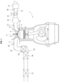
- FIG. 1 illustrates configurations of an internal combustion engine 1 for vehicle which employs a catalytic converter according to the first embodiment.
- the present invention is applied to the catalytic converter used in the internal combustion engine for generation to drive a generator of a series hybrid vehicle.
- Internal combustion engine 1 in the series hybrid vehicle is operated intermittently depending on generation request from the vehicle.
- the present invention is applicable not only to an internal combustion engine for a series hybrid vehicle, but also to an internal combustion engine for a parallel hybrid vehicle or simply an internal combustion engine for a vehicle structured to travel by output from the internal combustion engine.
- Internal combustion engine 1 is, for example, a four-stroke cycle spark ignition type internal combustion engine.
- Internal combustion engine 1 includes a pair of intake valves 4 and a pair of exhaust valves 5 in a ceiling wall of a combustion chamber 3, and includes a spark plug 6 in a central region surrounded by intake valves 4 and exhaust valves 5.
- Intake valves 4 are structured to open and close an intake port 15 below which a cylinder-injection fuel injection valve 16 is disposed.
- Cylinder-injection fuel injection valve 16 serves as a main fuel injection valve, and is structured to inject fuel directly into combustion chamber 3.
- Intake port 15 includes a port-injection fuel injection valve 12 for each cylinder.
- Port-injection fuel injection valve 12 is structured to inject fuel into intake port 15 and serve as a supplementary fuel injection valve to be operated under specific conditions.
- Each of cylinder-injection fuel injection valve 16 and port-injection fuel injection valve 12 is an electromagnetic or piezoelectric type injection valve structured to open in response to application of a drive pulse signal and inject fuel substantially proportional in amount to a pulse width of the drive pulse signal.
- one of cylinder-injection fuel injection valve 16 and port-injection fuel injection valve 12 may be omitted in case of avoiding such dual injection system.
- Intake port 15 is connected to an intake passage 14 that includes a collector 18 and an electronically controlled throttle valve 19 installed upstream with respect to collector 18. Throttle valve 19 has an opening degree controlled with a control signal from an engine controller not shown.
- Intake passage 14 further includes an air flow meter 20 structured to measure an amount of intake air and disposed upstream with respect to throttle valve 19, and includes an air cleaner 21 disposed upstream with respect to air flow meter 20.
- An exhaust port 17 is connected to an exhaust passage 25 that includes a preparatory catalytic converter 26 according to the first embodiment of the present invention and a main catalytic converter 27 disposed downstream with respect to preparatory catalytic converter 26. Upstream with respect to preparatory catalytic converter 26, an air-fuel ratio sensor 28 structured to measure an air-fuel ratio is disposed.
- Preparatory catalytic converter 26 is located at a relatively upstream position in the exhaust system, and is contained in an engine room of the vehicle.
- Main catalytic converter 27 is located under a floor of the vehicle.
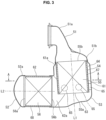
- FIG. 2 is a side view of preparatory catalytic converter 26, which is simply referred to as catalytic converter 26 in the following, according to the first embodiment.
- FIG. 3 is a longitudinal sectional view showing an internal structure of catalytic converter 26.
- catalytic converter 26 includes: an inlet-side diffuser 51 connected to an upstream-side exhaust passage such as an outlet of a collection part of an exhaust manifold; an outlet-side diffuser 52 connected to a downstream-side exhaust passage; a case 53 interposed between inlet-side diffuser 51 and outlet-side diffuser 52; an inner liner 54 disposed to form a double pipe structure in a region inside the case 53; and a first catalyst 55 and a second catalyst 56 each of which has a columnar shape and is disposed inside the case 53.
- Inlet-side diffuser 51 includes an exhaust pipe 51a and a circular wide diameter section 51b greater in diameter than exhaust pipe 51a, and is tapered to increase in diameter from exhaust pipe 51a to wide diameter section 51b.
- outlet-side diffuser 52 includes a circular wide diameter section 52a and an exhaust pipe 52b, and is tapered to decrease in diameter from wide diameter section 52a to exhaust pipe 52b.
- exhaust pipe 52b is connected to a branch pipe 57 for an EGR passage.
- Wide diameter section 51b of inlet-side diffuser 51 and wide diameter section 52a of outlet-side diffuser 52 are substantially equal to each other in diameter, and are disposed perpendicularly to each other.
- Case 53 connects inlet-side diffuser 51 to outlet-side diffuser 52, and is bent a substantially L-shape.
- case 53 includes an upstream-side cylindrical section 61 having a cylindrical shape and including a first end formed continuously with wide diameter section 51b of inlet-side diffuser 51, and includes a downstream-side cylindrical section 62 having a cylindrical shape and including a first end formed continuously with wide diameter section 52a of outlet-side diffuser 52, wherein a central axis L1 of upstream-side cylindrical section 61 and a central axis L2 of downstream-side cylindrical section 62 are perpendicular to each other.
- Upstream-side cylindrical section 61 and downstream-side cylindrical section 62 are combined in the L-shape, where: upstream-side cylindrical section 61 includes a second end opposite to inlet-side diffuser 51; downstream-side cylindrical section 62 includes a second end opposite to outlet-side diffuser 52; the second end of upstream-side cylindrical section 61 includes a peripheral face including a part in a circumferential direction around upstream-side cylindrical section 61 wherein the part is continuous with the second end of downstream-side cylindrical section 62 via a pair of crescent portions 62a.
- Upstream-side cylindrical section 61 is slightly greater in diameter than wide diameter section 51b of inlet-side diffuser 51, and is connected to inlet-side diffuser 51 via a taper section 61a having an annular shape.
- Downstream-side cylindrical section 62 is substantially equal in diameter to wide diameter section 52a of outlet-side diffuser 52, and includes the first end extending straight to be connected to outlet-side diffuser 52. Accordingly, upstream-side cylindrical section 61 is slightly greater in diameter than downstream-side cylindrical section 62, and each of crescent portions 62a is connected to upstream-side cylindrical section 61 so as to occupy an angle less than 180° in the peripheral face of upstream-side cylindrical section 61.
- the second end of upstream-side cylindrical section 61 opposite to inlet-side diffuser 51 is closed by a bottom wall 63 obliquely crossing the central axis L1.
- the peripheral face of the second end of upstream-side cylindrical section 61 is smoothly continuous with downstream-side cylindrical section 62 via bottom wall 63, except for regions occupied by crescent portions 62a.
- Case 53 exemplified in the drawings is formed by assembling separate components: i.e., the straight part of downstream-side cylindrical section 62, and a part including upstream-side cylindrical section 61 and crescent portions 62a.
- case 53 is not limited to an assembly of appropriately separated components, but may be an integrated single component.
- Inner liner 54 has a cylindrical shape in conformance in diameter with wide diameter section 51b of inlet-side diffuser 51, and includes a first end fixed to and supported by the upstream-side end of upstream-side cylindrical section 61 of case 53.
- the first end of inner liner 54 is fixed to a narrow diameter sided end of taper section 61a which is connected to wide diameter section 51b of inlet-side diffuser 51.
- FIG. 3 exemplarily shows that wide diameter section 51b of inlet-side diffuser 51 overlaps with an inner peripheral surface of taper section 61a, and the first end of inner liner 54 overlaps with an inner peripheral surface of inlet-side diffuser 51, these three members are not limited in how to overlap them. Furthermore, it is allowed, for example, to form inlet-side diffuser 51 and upstream-side cylindrical section 61 as an integrated single component or to form inlet-side diffuser 51 and inner liner 54 as an integrated single component.
- Inner liner 54 includes a second end that is a free end open inside the case 53 toward bottom wall 63.
- Inner liner 54 has a central axis coinciding with central axis L1 of upstream-side cylindrical section 61. Accordingly, inner liner 54 and upstream-side cylindrical section 61 compose the so-called double pipe structure, and form therebetween a gap serving as a flow passage 64 with an annular shape.
- the annular flow passage 64 is in communication with a space defined between bottom wall 63 and a tip of inner liner 54, because the tip of inner liner 54 is apart from bottom wall 63.
- Annular flow passage 64 has a flow passage cross sectional area (i.e.
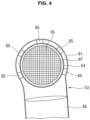
- Inner liner 54 is accompanied by a plurality of (e.g. five) supporters 65 each of which is heat conductive and is interposed between a peripheral face of the tip of inner liner 54 and upstream-side cylindrical section 61.
- each of supporters 65 is made of a metal mesh formed in a shape of column or disk. Accordingly, each of supporters 65 is elastically deformable and has a damping property.
- Supporters 65 are arranged at a plurality of (e.g. five) positions in a circumferential direction around inner liner 54 (see FIG. 4 ), in a vicinity of a tip edge of inner liner 54. This arrangement of supporters 65 at the plurality of positions serves to suppress vibration of the tip of inner liner 54 which is the free end.
- First catalyst 55 is composed of an upstream-side ceramic member serving as a catalyst carrier and a catalytic material (e.g. a three-way catalyst) coated on and carried by the upstream-side ceramic member.
- the upstream-side ceramic member has a columnar shape, and includes numerous minute passages extending in the axial direction.
- First catalyst 55 is retained inside the inner liner 54 via a mat 67 for cushioning.
- first catalyst 55 is a general three-way catalyst employing a so-called monolith catalyst carrier.
- First catalyst 55 includes a downstream-side (i.e. outlet-side) end face 55a coinciding in position with the tip edge of inner liner 54.
- first catalyst 55 includes an upstream-side (i.e.
- first catalyst 55 is substantially equal to inner liner 54 in entire length.
- the upstream-side end face 55b is positioned adjacently to inlet-side diffuser 51 formed to cover the end face 55b.
- Second catalyst 56 is a particulate collection filter composed of a downstream-side ceramic member and a catalytic material (e.g. a three-way catalyst) coated on and carried by the downstream-side ceramic member.
- the downstream-side ceramic member has a columnar shape, and includes numerous minute passages extending in the axial direction and including ends alternately sealed.
- second catalyst 56 is a general gasoline particulate filter (GPF) with a catalytic material carried by a so-called sealed type monolith catalyst carrier.
- GPF general gasoline particulate filter
- second catalyst 56 may be replaced with a particulate collection filter that does not carries a catalytic material.
- Second catalyst 56 is retained inside the downstream-side cylindrical section 62 via a mat 68 for cushioning.
- Second catalyst 56 has an entire length basically equal to a length of the straight part of downstream-side cylindrical section 62. Accordingly, second catalyst 56 includes a downstream-side (i.e. outlet-side) end face 56a positioned adjacently to outlet-side diffuser 52 formed to cover the end face 56a. Furthermore, second catalyst 56 includes an upstream-side (i.e. inlet-side) end face 56b that is open inside the case 53 at a position in a vicinity of boundaries between the straight part of downstream-side cylindrical section 62 and crescent portions 62a. In the drawings, first catalyst 55 and second catalyst 56 are exemplarily shown to be approximately equal to each other in diameter and axial length.
- end face 56b of second catalyst 56 faces the peripheral face of inner liner 54 such that a half or more in diameter of end face 56b overlaps with the peripheral face of inner liner 54.
- end face 56b includes a region projecting below the tip edge of inner liner 54 wherein the projecting region has a radial dimension less than a radius of second catalyst 56.
- End face 56b and the peripheral face of inner liner 54 form therebetween a gap that has a width equal to the gap serving as flow passage 64 in the double pipe structure described above (i.e. equal to a distance between inner liner 54 and upstream-side cylindrical section 61) or slightly wider than that.
- catalytic converter 26 configured as described above, exhaust gas discharged from the exhaust manifold passes first catalyst 55, and thereafter is changed in direction inside the case 53, and passes second catalyst 56, and then flows toward main catalytic converter 27 disposed under the floor of the vehicle.
- the catalysts 55 and 56 is cooled by outside air.
- catalysts 55 and 56 undergo cooling effect due to vehicle traveling wind.
- first catalyst 55 is slowed in temperature fall caused by the vehicle traveling wind during the stop of internal combustion engine 1, because of thermal insulation effect and heat retaining effect due to the gap serving as flow passage 64 between inner liner 54 and upstream-side cylindrical section 61 that compose the so-called double pipe structure. This allows catalytic effect to be exerted relatively early after operation restart of internal combustion engine 1.
- first catalyst 55 is positioned in the upstream side, and tends to rise in temperature in case of continuous high-load operation of internal combustion engine 1. Especially, the tip of first catalyst 55, which is the free end, is likely to undergo excessive temperature rise. In case of such temperature rise in first catalyst 55, heat is transferred from first catalyst 55 to case 53 via supporters 65 that are heat conductive. This serves to suppress the tip of first catalyst 55, which is easier to rise in temperature, from undergoing the excessive temperature rise, and relax thermal deterioration of first catalyst 55.
- the exhaust gas discharged from downstream-side end face 55a of first catalyst 55 partially flows along bottom wall 63 and then into second catalyst 56, while partially flowing through annular flow passage 64 between inner liner 54 and upstream-side cylindrical section 61 in the axial direction and the circumferential direction (i.e. substantially helically) and then into second catalyst 56.
- This allows the exhaust gas from first catalyst 55 to smoothly flow even toward a region of second catalyst 56 in which second catalyst 56 overlaps with the peripheral face of inner liner 54. This serves to guide the exhaust gas to end face 56b widely dispersively, and reduce local bias of the exhaust gas.
- the exhaust gas is certainly guided also to the region of end face 56b overlapping with inner liner 54, via annular flow passage 64 in the double pipe structure.
- the exhaust gas is allowed to flow smoothly enough, even in case, as described above, that the half or more in diameter of end face 56b of second catalyst 56 overlaps with inner liner 54.
- the amount of the overlapping is approximately 60% to 70% of the diameter of end face 56b.
- Such increase in amount of the overlapping serves to downsize catalytic converter 26 in external dimension (in particular, in vertical dimension in FIG. 3 ).
- Annular flow passage 64 is uniform in width through an entire circumference around inner liner 54. This allows annular flow passage 64 to be increased in flow passage cross sectional area, by configuring the upstream-side cylindrical section 61 to be slightly greater in diameter than inner liner 54. This serves to establish the smooth flow of exhaust gas toward second catalyst 56, while forming the catalytic converter 26 (in particular, upstream-side cylindrical section 61) to be relatively small in external dimension.
- each of supporters 65 has a circular external shape, and thereby does not impair the flow of exhaust gas.
- Supporters 65 are not limited to the circular ones shown in the drawings, and may be formed in various shapes.
- FIG. 6 shows that one of supporters 65 is shaped slender and is inclined with respect to central axis L1 of upstream-side cylindrical section 61 so as to extend along the exhaust flow flowing from end face 55a of first catalyst 55 toward end face 56b of second catalyst 56 via flow passage 64.
- this one of supporters 65 is made of a heat-conductive metal mesh formed in the slender rod shape.
- another of supporters 65 disposed on the peripheral face in an opposite side to a side drawn in FIG. 6 is inclined symmetrically to the supporter 65 drawn in FIG. 6 .
- one of supporters 65 disposed on the peripheral face in an opposite side to end face 56b of second catalyst 56 may be parallel with central axis L1.
- upstream-side cylindrical section 61 includes a bead 69 bulging outwardly, at a position slightly upstream with respect to positions of supporters 65 in the axial direction of inner liner 54.
- Bead 69 extends continuously in the circumferential direction around upstream-side cylindrical section 61, and is adjacent to ends of supporters 65.
- Bead 69 increases annular flow passage 64 in flow passage cross sectional area (i.e. cross sectional area at a cross section perpendicular to central axis L1) partially. This serves to cancel out increase in passage resistance caused by supporters 65 disposed in flow passage 64.
- First catalyst 55 may be composed of a plurality of split monolith catalysts, although first catalyst 55 according to the embodiment shown in FIGs. 3 and 4 is the single monolith catalyst. For example, it is allowed to employ a front catalyst and a rear catalyst which are different from each other in characteristics, and are arranged in series, and are contained in inner liner 54.
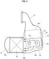
- FIG. 7 shows a second embodiment in which catalytic converter 26 further includes an electrically-heated catalyst (EHC) 71 between inlet-side diffuser 51 and first catalyst 55.
- Electrically-heated catalyst 71 has a columnar shape relatively short in axial dimension, i.e. a flat disk shape, and is disposed upstream with respect to first catalyst 55, in series with first catalyst 55.
- Electrically-heated catalyst 71 is, for example, a member formed by coating a metallic catalytic carrier with a catalytic material so as to generate heat in response to energization, although this may be modified variously. Electrically-heated catalyst 71 in an example in the drawing is retained inside the inner liner 54 together with first catalyst 55, via a mat 72.
- electrically-heated catalyst 71 does not need a structure for thermal insulation and heat retaining, because electrically-heated catalyst 71 is structured to allow the catalyst therein to be activated by energization when being cold.
- inner liner 54 composes a so-called single pipe structure within a part containing the electrically-heated catalyst 71, wherein the part is exposed to the outside without being covered by upstream-side cylindrical section 61 defining the annular flow passage 64.
- taper section 61a which is the end of upstream-side cylindrical section 61, is positioned in a vicinity of a border between electrically-heated catalyst 71 and first catalyst 55.
- first catalyst 55 is smaller in axial dimension than the first embodiment shown in FIGs. 3 and 4 , because first catalyst 55 needs a less capacity due to addition of electrically-heated catalyst 71.
- this first catalyst 55 may be naturally replaced with one that has a size equivalent to first catalyst 55 in FIGs. 3 and 4 .
Landscapes
- Engineering & Computer Science (AREA)
- Chemical & Material Sciences (AREA)
- Chemical Kinetics & Catalysis (AREA)
- Combustion & Propulsion (AREA)
- General Engineering & Computer Science (AREA)
- Mechanical Engineering (AREA)
- Health & Medical Sciences (AREA)
- Toxicology (AREA)
- Biomedical Technology (AREA)
- Environmental & Geological Engineering (AREA)
- Analytical Chemistry (AREA)
- General Chemical & Material Sciences (AREA)
- Oil, Petroleum & Natural Gas (AREA)
- Ceramic Engineering (AREA)
- Materials Engineering (AREA)
- Exhaust Gas After Treatment (AREA)
Applications Claiming Priority (1)
| Application Number | Priority Date | Filing Date | Title |
|---|---|---|---|
| PCT/IB2019/000566 WO2020234618A1 (ja) | 2019-05-22 | 2019-05-22 | 触媒コンバータ |
Publications (3)
| Publication Number | Publication Date |
|---|---|
| EP3974628A1 EP3974628A1 (en) | 2022-03-30 |
| EP3974628A4 EP3974628A4 (en) | 2022-06-01 |
| EP3974628B1 true EP3974628B1 (en) | 2023-08-16 |
Family
ID=73458078
Family Applications (1)
| Application Number | Title | Priority Date | Filing Date |
|---|---|---|---|
| EP19929204.6A Active EP3974628B1 (en) | 2019-05-22 | 2019-05-22 | Catalytic converter |
Country Status (5)
| Country | Link |
|---|---|
| US (1) | US11623180B2 (enExample) |
| EP (1) | EP3974628B1 (enExample) |
| JP (1) | JP7159465B2 (enExample) |
| CN (1) | CN113906199B (enExample) |
| WO (1) | WO2020234618A1 (enExample) |
Families Citing this family (3)
| Publication number | Priority date | Publication date | Assignee | Title |
|---|---|---|---|---|
| WO2020145050A1 (ja) * | 2019-01-09 | 2020-07-16 | マレリ株式会社 | 排気ガス処理装置 |
| JP7145307B1 (ja) * | 2021-08-05 | 2022-09-30 | マレリ株式会社 | 排気ガス処理装置 |
| JP2025111026A (ja) * | 2024-01-17 | 2025-07-30 | トヨタ自動車株式会社 | 内燃機関の排気浄化装置 |
Family Cites Families (25)
| Publication number | Priority date | Publication date | Assignee | Title |
|---|---|---|---|---|
| DE3524775C1 (de) * | 1985-07-11 | 1986-09-04 | Daimler-Benz Ag, 7000 Stuttgart | In einem metallenen Gehaeuse angeordneter monolithischer Abgaskatalysator |
| JPH06101465A (ja) * | 1992-09-22 | 1994-04-12 | Nissan Motor Co Ltd | 2重管触媒コンバータ |
| JPH0725212U (ja) | 1993-09-30 | 1995-05-12 | 株式会社小松製作所 | 内燃機関の排気ガス浄化装置 |
| US5693295A (en) * | 1996-01-16 | 1997-12-02 | General Motors Corporation | Catalytic converter |
| JP3099733B2 (ja) * | 1996-05-09 | 2000-10-16 | 株式会社ディー・ビー・エス | 小型エンジン用排気ガス浄化装置 |
| US6713025B1 (en) * | 1999-09-15 | 2004-03-30 | Daimlerchrysler Corporation | Light-off and close coupled catalyst |
| JP2003049634A (ja) * | 2001-08-03 | 2003-02-21 | Calsonic Kansei Corp | 車両用パーティキュレートフィルタ |
| JP2005264769A (ja) * | 2004-03-17 | 2005-09-29 | Nissan Motor Co Ltd | 内燃機関の触媒コンバータ |
| JP2007083189A (ja) * | 2005-09-22 | 2007-04-05 | Mazda Motor Corp | 触媒コンバータおよび排気システム |
| JP2009156071A (ja) * | 2007-12-25 | 2009-07-16 | Mitsubishi Motors Corp | 内燃機関の排気ガス浄化装置 |
| JP5032409B2 (ja) * | 2008-07-28 | 2012-09-26 | 三菱ふそうトラック・バス株式会社 | 排気浄化装置 |
| DE102009024718A1 (de) * | 2009-06-12 | 2010-12-16 | Emitec Gesellschaft Für Emissionstechnologie Mbh | Abgasbehandlungsvorrichtung für den motornahen Einsatz |
| JP5368959B2 (ja) | 2009-12-07 | 2013-12-18 | 日本碍子株式会社 | 排ガス処理装置 |
| DE102011075643A1 (de) * | 2011-05-11 | 2012-11-15 | J. Eberspächer GmbH & Co. KG | Abgasanlagenkomponente |
| EP2770177B1 (en) * | 2011-10-18 | 2018-01-31 | Toyota Jidosha Kabushiki Kaisha | Electrically heated catalyst |
| WO2013137105A1 (ja) * | 2012-03-13 | 2013-09-19 | 日産自動車株式会社 | 触媒コンバータ |
| JP2014031743A (ja) * | 2012-08-02 | 2014-02-20 | Bosch Corp | 内燃機関の排気浄化装置 |
| KR101379780B1 (ko) * | 2013-01-17 | 2014-04-04 | 가부시키가이샤 고마쓰 세이사쿠쇼 | 환원제 수용액 믹싱 장치 및 이것을 구비한 배기 가스 후처리 장치 |
| US9223715B2 (en) * | 2013-08-21 | 2015-12-29 | Via Alliance Semiconductor Co., Ltd. | Microprocessor mechanism for decompression of cache correction data |
| JP2015098834A (ja) | 2013-11-19 | 2015-05-28 | トヨタ自動車株式会社 | 内燃機関の触媒装置 |
| US9551266B2 (en) * | 2014-05-15 | 2017-01-24 | GM Global Technology Operations LLC | External exhaust guiding flow chambers for multiple catalyst architecture |
| EP2960456B1 (en) * | 2014-06-27 | 2017-04-12 | Volvo Car Corporation | Angled and compact exhaust gas aftertreatment device |
| DE102016114283A1 (de) | 2016-08-02 | 2018-02-08 | Benteler Automobiltechnik Gmbh | Abgasnachbehandlungsanordnung |
| JP6299856B1 (ja) | 2016-12-16 | 2018-03-28 | マツダ株式会社 | エンジンの排気装置 |
| CN108571368B (zh) * | 2017-03-10 | 2020-06-16 | 马自达汽车株式会社 | 发动机的排气装置 |
-
2019
- 2019-05-22 US US17/612,769 patent/US11623180B2/en active Active
- 2019-05-22 EP EP19929204.6A patent/EP3974628B1/en active Active
- 2019-05-22 WO PCT/IB2019/000566 patent/WO2020234618A1/ja not_active Ceased
- 2019-05-22 CN CN201980096477.5A patent/CN113906199B/zh active Active
- 2019-05-22 JP JP2021520476A patent/JP7159465B2/ja active Active
Also Published As
| Publication number | Publication date |
|---|---|
| EP3974628A1 (en) | 2022-03-30 |
| US11623180B2 (en) | 2023-04-11 |
| WO2020234618A1 (ja) | 2020-11-26 |
| JPWO2020234618A1 (enExample) | 2020-11-26 |
| CN113906199A (zh) | 2022-01-07 |
| US20220274060A1 (en) | 2022-09-01 |
| CN113906199B (zh) | 2023-11-28 |
| EP3974628A4 (en) | 2022-06-01 |
| JP7159465B2 (ja) | 2022-10-24 |
Similar Documents
| Publication | Publication Date | Title |
|---|---|---|
| JP6034438B2 (ja) | エンジンに近接して使用するための排気ガス処理装置 | |
| US9551266B2 (en) | External exhaust guiding flow chambers for multiple catalyst architecture | |
| EP3974628B1 (en) | Catalytic converter | |
| CN108571368B (zh) | 发动机的排气装置 | |
| JP6299856B1 (ja) | エンジンの排気装置 | |
| US10557398B2 (en) | Exhaust pipe structure for internal combustion engine | |
| US11293328B2 (en) | Mixer baffle with integrated sensor | |
| RU2716774C2 (ru) | Смеситель карбамида | |
| CN110088442B (zh) | 发动机的排气装置 | |
| US20170321592A1 (en) | Compact Inline Inlet With Integrated Cast Ring | |
| US9115627B2 (en) | Multiple skewed channel bricks mounted in opposing clocking directions | |
| CN117460881A (zh) | 用于车辆排气系统的表面部件 | |
| CN107605585A (zh) | 废气密封件 | |
| JP6319412B1 (ja) | エンジンの排気装置 | |
| JP6729721B2 (ja) | エンジンの排気装置 | |
| US10557443B2 (en) | Exhaust device of engine | |
| JP2025070259A (ja) | 内燃機関の排気管 | |
| CN110195632B (zh) | 内燃机的废气净化装置 | |
| IT202300016404A1 (it) | Motore a combustione interna con scambiatore di calore per egr | |
| JP2021105390A (ja) | 排気浄化装置 | |
| JP2020045897A (ja) | 触媒コンバータ | |
| JP2008163917A (ja) | 排気ガス浄化装置 | |
| JP2018123786A (ja) | 排気ガス浄化装置 |
Legal Events
| Date | Code | Title | Description |
|---|---|---|---|
| STAA | Information on the status of an ep patent application or granted ep patent |
Free format text: STATUS: THE INTERNATIONAL PUBLICATION HAS BEEN MADE |
|
| PUAI | Public reference made under article 153(3) epc to a published international application that has entered the european phase |
Free format text: ORIGINAL CODE: 0009012 |
|
| STAA | Information on the status of an ep patent application or granted ep patent |
Free format text: STATUS: REQUEST FOR EXAMINATION WAS MADE |
|
| 17P | Request for examination filed |
Effective date: 20211202 |
|
| AK | Designated contracting states |
Kind code of ref document: A1 Designated state(s): AL AT BE BG CH CY CZ DE DK EE ES FI FR GB GR HR HU IE IS IT LI LT LU LV MC MK MT NL NO PL PT RO RS SE SI SK SM TR |
|
| A4 | Supplementary search report drawn up and despatched |
Effective date: 20220429 |
|
| RIC1 | Information provided on ipc code assigned before grant |
Ipc: F01N 3/24 20060101AFI20220422BHEP |
|
| RAP3 | Party data changed (applicant data changed or rights of an application transferred) |
Owner name: RENAULT S.A.S Owner name: NISSAN MOTOR CO., LTD. |
|
| DAV | Request for validation of the european patent (deleted) | ||
| DAX | Request for extension of the european patent (deleted) | ||
| GRAP | Despatch of communication of intention to grant a patent |
Free format text: ORIGINAL CODE: EPIDOSNIGR1 |
|
| STAA | Information on the status of an ep patent application or granted ep patent |
Free format text: STATUS: GRANT OF PATENT IS INTENDED |
|
| GRAS | Grant fee paid |
Free format text: ORIGINAL CODE: EPIDOSNIGR3 |
|
| INTG | Intention to grant announced |
Effective date: 20230614 |
|
| GRAA | (expected) grant |
Free format text: ORIGINAL CODE: 0009210 |
|
| STAA | Information on the status of an ep patent application or granted ep patent |
Free format text: STATUS: THE PATENT HAS BEEN GRANTED |
|
| AK | Designated contracting states |
Kind code of ref document: B1 Designated state(s): AL AT BE BG CH CY CZ DE DK EE ES FI FR GB GR HR HU IE IS IT LI LT LU LV MC MK MT NL NO PL PT RO RS SE SI SK SM TR |
|
| REG | Reference to a national code |
Ref country code: CH Ref legal event code: EP |
|
| REG | Reference to a national code |
Ref country code: DE Ref legal event code: R096 Ref document number: 602019035367 Country of ref document: DE |
|
| REG | Reference to a national code |
Ref country code: IE Ref legal event code: FG4D |
|
| REG | Reference to a national code |
Ref country code: LT Ref legal event code: MG9D |
|
| REG | Reference to a national code |
Ref country code: NL Ref legal event code: MP Effective date: 20230816 |
|
| REG | Reference to a national code |
Ref country code: AT Ref legal event code: MK05 Ref document number: 1600263 Country of ref document: AT Kind code of ref document: T Effective date: 20230816 |
|
| PG25 | Lapsed in a contracting state [announced via postgrant information from national office to epo] |
Ref country code: GR Free format text: LAPSE BECAUSE OF FAILURE TO SUBMIT A TRANSLATION OF THE DESCRIPTION OR TO PAY THE FEE WITHIN THE PRESCRIBED TIME-LIMIT Effective date: 20231117 |
|
| PG25 | Lapsed in a contracting state [announced via postgrant information from national office to epo] |
Ref country code: IS Free format text: LAPSE BECAUSE OF FAILURE TO SUBMIT A TRANSLATION OF THE DESCRIPTION OR TO PAY THE FEE WITHIN THE PRESCRIBED TIME-LIMIT Effective date: 20231216 |
|
| PG25 | Lapsed in a contracting state [announced via postgrant information from national office to epo] |
Ref country code: SE Free format text: LAPSE BECAUSE OF FAILURE TO SUBMIT A TRANSLATION OF THE DESCRIPTION OR TO PAY THE FEE WITHIN THE PRESCRIBED TIME-LIMIT Effective date: 20230816 Ref country code: RS Free format text: LAPSE BECAUSE OF FAILURE TO SUBMIT A TRANSLATION OF THE DESCRIPTION OR TO PAY THE FEE WITHIN THE PRESCRIBED TIME-LIMIT Effective date: 20230816 Ref country code: PT Free format text: LAPSE BECAUSE OF FAILURE TO SUBMIT A TRANSLATION OF THE DESCRIPTION OR TO PAY THE FEE WITHIN THE PRESCRIBED TIME-LIMIT Effective date: 20231218 Ref country code: NO Free format text: LAPSE BECAUSE OF FAILURE TO SUBMIT A TRANSLATION OF THE DESCRIPTION OR TO PAY THE FEE WITHIN THE PRESCRIBED TIME-LIMIT Effective date: 20231116 Ref country code: NL Free format text: LAPSE BECAUSE OF FAILURE TO SUBMIT A TRANSLATION OF THE DESCRIPTION OR TO PAY THE FEE WITHIN THE PRESCRIBED TIME-LIMIT Effective date: 20230816 Ref country code: LV Free format text: LAPSE BECAUSE OF FAILURE TO SUBMIT A TRANSLATION OF THE DESCRIPTION OR TO PAY THE FEE WITHIN THE PRESCRIBED TIME-LIMIT Effective date: 20230816 Ref country code: LT Free format text: LAPSE BECAUSE OF FAILURE TO SUBMIT A TRANSLATION OF THE DESCRIPTION OR TO PAY THE FEE WITHIN THE PRESCRIBED TIME-LIMIT Effective date: 20230816 Ref country code: IS Free format text: LAPSE BECAUSE OF FAILURE TO SUBMIT A TRANSLATION OF THE DESCRIPTION OR TO PAY THE FEE WITHIN THE PRESCRIBED TIME-LIMIT Effective date: 20231216 Ref country code: HR Free format text: LAPSE BECAUSE OF FAILURE TO SUBMIT A TRANSLATION OF THE DESCRIPTION OR TO PAY THE FEE WITHIN THE PRESCRIBED TIME-LIMIT Effective date: 20230816 Ref country code: GR Free format text: LAPSE BECAUSE OF FAILURE TO SUBMIT A TRANSLATION OF THE DESCRIPTION OR TO PAY THE FEE WITHIN THE PRESCRIBED TIME-LIMIT Effective date: 20231117 Ref country code: FI Free format text: LAPSE BECAUSE OF FAILURE TO SUBMIT A TRANSLATION OF THE DESCRIPTION OR TO PAY THE FEE WITHIN THE PRESCRIBED TIME-LIMIT Effective date: 20230816 Ref country code: AT Free format text: LAPSE BECAUSE OF FAILURE TO SUBMIT A TRANSLATION OF THE DESCRIPTION OR TO PAY THE FEE WITHIN THE PRESCRIBED TIME-LIMIT Effective date: 20230816 |
|
| PG25 | Lapsed in a contracting state [announced via postgrant information from national office to epo] |
Ref country code: PL Free format text: LAPSE BECAUSE OF FAILURE TO SUBMIT A TRANSLATION OF THE DESCRIPTION OR TO PAY THE FEE WITHIN THE PRESCRIBED TIME-LIMIT Effective date: 20230816 |
|
| PG25 | Lapsed in a contracting state [announced via postgrant information from national office to epo] |
Ref country code: ES Free format text: LAPSE BECAUSE OF FAILURE TO SUBMIT A TRANSLATION OF THE DESCRIPTION OR TO PAY THE FEE WITHIN THE PRESCRIBED TIME-LIMIT Effective date: 20230816 |
|
| PG25 | Lapsed in a contracting state [announced via postgrant information from national office to epo] |
Ref country code: SM Free format text: LAPSE BECAUSE OF FAILURE TO SUBMIT A TRANSLATION OF THE DESCRIPTION OR TO PAY THE FEE WITHIN THE PRESCRIBED TIME-LIMIT Effective date: 20230816 Ref country code: RO Free format text: LAPSE BECAUSE OF FAILURE TO SUBMIT A TRANSLATION OF THE DESCRIPTION OR TO PAY THE FEE WITHIN THE PRESCRIBED TIME-LIMIT Effective date: 20230816 Ref country code: ES Free format text: LAPSE BECAUSE OF FAILURE TO SUBMIT A TRANSLATION OF THE DESCRIPTION OR TO PAY THE FEE WITHIN THE PRESCRIBED TIME-LIMIT Effective date: 20230816 Ref country code: EE Free format text: LAPSE BECAUSE OF FAILURE TO SUBMIT A TRANSLATION OF THE DESCRIPTION OR TO PAY THE FEE WITHIN THE PRESCRIBED TIME-LIMIT Effective date: 20230816 Ref country code: DK Free format text: LAPSE BECAUSE OF FAILURE TO SUBMIT A TRANSLATION OF THE DESCRIPTION OR TO PAY THE FEE WITHIN THE PRESCRIBED TIME-LIMIT Effective date: 20230816 Ref country code: CZ Free format text: LAPSE BECAUSE OF FAILURE TO SUBMIT A TRANSLATION OF THE DESCRIPTION OR TO PAY THE FEE WITHIN THE PRESCRIBED TIME-LIMIT Effective date: 20230816 Ref country code: SK Free format text: LAPSE BECAUSE OF FAILURE TO SUBMIT A TRANSLATION OF THE DESCRIPTION OR TO PAY THE FEE WITHIN THE PRESCRIBED TIME-LIMIT Effective date: 20230816 |
|
| REG | Reference to a national code |
Ref country code: DE Ref legal event code: R097 Ref document number: 602019035367 Country of ref document: DE |
|
| PLBE | No opposition filed within time limit |
Free format text: ORIGINAL CODE: 0009261 |
|
| STAA | Information on the status of an ep patent application or granted ep patent |
Free format text: STATUS: NO OPPOSITION FILED WITHIN TIME LIMIT |
|
| 26N | No opposition filed |
Effective date: 20240517 |
|
| PG25 | Lapsed in a contracting state [announced via postgrant information from national office to epo] |
Ref country code: IT Free format text: LAPSE BECAUSE OF FAILURE TO SUBMIT A TRANSLATION OF THE DESCRIPTION OR TO PAY THE FEE WITHIN THE PRESCRIBED TIME-LIMIT Effective date: 20230816 Ref country code: SI Free format text: LAPSE BECAUSE OF FAILURE TO SUBMIT A TRANSLATION OF THE DESCRIPTION OR TO PAY THE FEE WITHIN THE PRESCRIBED TIME-LIMIT Effective date: 20230816 |
|
| PG25 | Lapsed in a contracting state [announced via postgrant information from national office to epo] |
Ref country code: BG Free format text: LAPSE BECAUSE OF FAILURE TO SUBMIT A TRANSLATION OF THE DESCRIPTION OR TO PAY THE FEE WITHIN THE PRESCRIBED TIME-LIMIT Effective date: 20230816 |
|
| PG25 | Lapsed in a contracting state [announced via postgrant information from national office to epo] |
Ref country code: BG Free format text: LAPSE BECAUSE OF FAILURE TO SUBMIT A TRANSLATION OF THE DESCRIPTION OR TO PAY THE FEE WITHIN THE PRESCRIBED TIME-LIMIT Effective date: 20230816 |
|
| REG | Reference to a national code |
Ref country code: CH Ref legal event code: PL |
|
| PG25 | Lapsed in a contracting state [announced via postgrant information from national office to epo] |
Ref country code: MC Free format text: LAPSE BECAUSE OF FAILURE TO SUBMIT A TRANSLATION OF THE DESCRIPTION OR TO PAY THE FEE WITHIN THE PRESCRIBED TIME-LIMIT Effective date: 20230816 |
|
| PG25 | Lapsed in a contracting state [announced via postgrant information from national office to epo] |
Ref country code: LU Free format text: LAPSE BECAUSE OF NON-PAYMENT OF DUE FEES Effective date: 20240522 |
|
| PG25 | Lapsed in a contracting state [announced via postgrant information from national office to epo] |
Ref country code: MC Free format text: LAPSE BECAUSE OF FAILURE TO SUBMIT A TRANSLATION OF THE DESCRIPTION OR TO PAY THE FEE WITHIN THE PRESCRIBED TIME-LIMIT Effective date: 20230816 Ref country code: LU Free format text: LAPSE BECAUSE OF NON-PAYMENT OF DUE FEES Effective date: 20240522 Ref country code: CH Free format text: LAPSE BECAUSE OF NON-PAYMENT OF DUE FEES Effective date: 20240531 |
|
| REG | Reference to a national code |
Ref country code: BE Ref legal event code: MM Effective date: 20240531 |
|
| PG25 | Lapsed in a contracting state [announced via postgrant information from national office to epo] |
Ref country code: IE Free format text: LAPSE BECAUSE OF NON-PAYMENT OF DUE FEES Effective date: 20240522 |
|
| PG25 | Lapsed in a contracting state [announced via postgrant information from national office to epo] |
Ref country code: BE Free format text: LAPSE BECAUSE OF NON-PAYMENT OF DUE FEES Effective date: 20240531 |
|
| PGFP | Annual fee paid to national office [announced via postgrant information from national office to epo] |
Ref country code: DE Payment date: 20250423 Year of fee payment: 7 |
|
| PGFP | Annual fee paid to national office [announced via postgrant information from national office to epo] |
Ref country code: GB Payment date: 20250423 Year of fee payment: 7 |
|
| PGFP | Annual fee paid to national office [announced via postgrant information from national office to epo] |
Ref country code: FR Payment date: 20250423 Year of fee payment: 7 |
|
| PG25 | Lapsed in a contracting state [announced via postgrant information from national office to epo] |
Ref country code: CY Free format text: LAPSE BECAUSE OF FAILURE TO SUBMIT A TRANSLATION OF THE DESCRIPTION OR TO PAY THE FEE WITHIN THE PRESCRIBED TIME-LIMIT; INVALID AB INITIO Effective date: 20190522 |
|
| PG25 | Lapsed in a contracting state [announced via postgrant information from national office to epo] |
Ref country code: HU Free format text: LAPSE BECAUSE OF FAILURE TO SUBMIT A TRANSLATION OF THE DESCRIPTION OR TO PAY THE FEE WITHIN THE PRESCRIBED TIME-LIMIT; INVALID AB INITIO Effective date: 20190522 |