WO2020234618A1 - 触媒コンバータ - Google Patents
触媒コンバータ Download PDFInfo
- Publication number
- WO2020234618A1 WO2020234618A1 PCT/IB2019/000566 IB2019000566W WO2020234618A1 WO 2020234618 A1 WO2020234618 A1 WO 2020234618A1 IB 2019000566 W IB2019000566 W IB 2019000566W WO 2020234618 A1 WO2020234618 A1 WO 2020234618A1
- Authority
- WO
- WIPO (PCT)
- Prior art keywords
- upstream
- catalyst
- cylindrical portion
- inner liner
- downstream
- Prior art date
- Legal status (The legal status is an assumption and is not a legal conclusion. Google has not performed a legal analysis and makes no representation as to the accuracy of the status listed.)
- Ceased
Links
Images
Classifications
-
- F—MECHANICAL ENGINEERING; LIGHTING; HEATING; WEAPONS; BLASTING
- F01—MACHINES OR ENGINES IN GENERAL; ENGINE PLANTS IN GENERAL; STEAM ENGINES
- F01N—GAS-FLOW SILENCERS OR EXHAUST APPARATUS FOR MACHINES OR ENGINES IN GENERAL; GAS-FLOW SILENCERS OR EXHAUST APPARATUS FOR INTERNAL-COMBUSTION ENGINES
- F01N3/00—Exhaust or silencing apparatus having means for purifying, rendering innocuous, or otherwise treating exhaust
- F01N3/02—Exhaust or silencing apparatus having means for purifying, rendering innocuous, or otherwise treating exhaust for cooling, or for removing solid constituents of, exhaust
- F01N3/021—Exhaust or silencing apparatus having means for purifying, rendering innocuous, or otherwise treating exhaust for cooling, or for removing solid constituents of, exhaust by means of filters
-
- B—PERFORMING OPERATIONS; TRANSPORTING
- B01—PHYSICAL OR CHEMICAL PROCESSES OR APPARATUS IN GENERAL
- B01D—SEPARATION
- B01D53/00—Separation of gases or vapours; Recovering vapours of volatile solvents from gases; Chemical or biological purification of waste gases, e.g. engine exhaust gases, smoke, fumes, flue gases, aerosols
- B01D53/34—Chemical or biological purification of waste gases
- B01D53/92—Chemical or biological purification of waste gases of engine exhaust gases
- B01D53/94—Chemical or biological purification of waste gases of engine exhaust gases by catalytic processes
- B01D53/9445—Simultaneously removing carbon monoxide, hydrocarbons or nitrogen oxides making use of three-way catalysts [TWC] or four-way-catalysts [FWC]
- B01D53/9454—Simultaneously removing carbon monoxide, hydrocarbons or nitrogen oxides making use of three-way catalysts [TWC] or four-way-catalysts [FWC] characterised by a specific device
-
- B—PERFORMING OPERATIONS; TRANSPORTING
- B01—PHYSICAL OR CHEMICAL PROCESSES OR APPARATUS IN GENERAL
- B01D—SEPARATION
- B01D53/00—Separation of gases or vapours; Recovering vapours of volatile solvents from gases; Chemical or biological purification of waste gases, e.g. engine exhaust gases, smoke, fumes, flue gases, aerosols
- B01D53/34—Chemical or biological purification of waste gases
- B01D53/92—Chemical or biological purification of waste gases of engine exhaust gases
- B01D53/94—Chemical or biological purification of waste gases of engine exhaust gases by catalytic processes
- B01D53/9445—Simultaneously removing carbon monoxide, hydrocarbons or nitrogen oxides making use of three-way catalysts [TWC] or four-way-catalysts [FWC]
- B01D53/945—Simultaneously removing carbon monoxide, hydrocarbons or nitrogen oxides making use of three-way catalysts [TWC] or four-way-catalysts [FWC] characterised by a specific catalyst
-
- F—MECHANICAL ENGINEERING; LIGHTING; HEATING; WEAPONS; BLASTING
- F01—MACHINES OR ENGINES IN GENERAL; ENGINE PLANTS IN GENERAL; STEAM ENGINES
- F01N—GAS-FLOW SILENCERS OR EXHAUST APPARATUS FOR MACHINES OR ENGINES IN GENERAL; GAS-FLOW SILENCERS OR EXHAUST APPARATUS FOR INTERNAL-COMBUSTION ENGINES
- F01N13/00—Exhaust or silencing apparatus characterised by constructional features
- F01N13/009—Exhaust or silencing apparatus characterised by constructional features having two or more separate purifying devices arranged in series
- F01N13/0097—Exhaust or silencing apparatus characterised by constructional features having two or more separate purifying devices arranged in series the purifying devices are arranged in a single housing
-
- F—MECHANICAL ENGINEERING; LIGHTING; HEATING; WEAPONS; BLASTING
- F01—MACHINES OR ENGINES IN GENERAL; ENGINE PLANTS IN GENERAL; STEAM ENGINES
- F01N—GAS-FLOW SILENCERS OR EXHAUST APPARATUS FOR MACHINES OR ENGINES IN GENERAL; GAS-FLOW SILENCERS OR EXHAUST APPARATUS FOR INTERNAL-COMBUSTION ENGINES
- F01N3/00—Exhaust or silencing apparatus having means for purifying, rendering innocuous, or otherwise treating exhaust
- F01N3/02—Exhaust or silencing apparatus having means for purifying, rendering innocuous, or otherwise treating exhaust for cooling, or for removing solid constituents of, exhaust
- F01N3/021—Exhaust or silencing apparatus having means for purifying, rendering innocuous, or otherwise treating exhaust for cooling, or for removing solid constituents of, exhaust by means of filters
- F01N3/022—Exhaust or silencing apparatus having means for purifying, rendering innocuous, or otherwise treating exhaust for cooling, or for removing solid constituents of, exhaust by means of filters characterised by specially adapted filtering structure, e.g. honeycomb, mesh or fibrous
- F01N3/0222—Exhaust or silencing apparatus having means for purifying, rendering innocuous, or otherwise treating exhaust for cooling, or for removing solid constituents of, exhaust by means of filters characterised by specially adapted filtering structure, e.g. honeycomb, mesh or fibrous the structure being monolithic, e.g. honeycombs
-
- F—MECHANICAL ENGINEERING; LIGHTING; HEATING; WEAPONS; BLASTING
- F01—MACHINES OR ENGINES IN GENERAL; ENGINE PLANTS IN GENERAL; STEAM ENGINES
- F01N—GAS-FLOW SILENCERS OR EXHAUST APPARATUS FOR MACHINES OR ENGINES IN GENERAL; GAS-FLOW SILENCERS OR EXHAUST APPARATUS FOR INTERNAL-COMBUSTION ENGINES
- F01N3/00—Exhaust or silencing apparatus having means for purifying, rendering innocuous, or otherwise treating exhaust
- F01N3/02—Exhaust or silencing apparatus having means for purifying, rendering innocuous, or otherwise treating exhaust for cooling, or for removing solid constituents of, exhaust
- F01N3/021—Exhaust or silencing apparatus having means for purifying, rendering innocuous, or otherwise treating exhaust for cooling, or for removing solid constituents of, exhaust by means of filters
- F01N3/033—Exhaust or silencing apparatus having means for purifying, rendering innocuous, or otherwise treating exhaust for cooling, or for removing solid constituents of, exhaust by means of filters in combination with other devices
- F01N3/035—Exhaust or silencing apparatus having means for purifying, rendering innocuous, or otherwise treating exhaust for cooling, or for removing solid constituents of, exhaust by means of filters in combination with other devices with catalytic reactors
-
- F—MECHANICAL ENGINEERING; LIGHTING; HEATING; WEAPONS; BLASTING
- F01—MACHINES OR ENGINES IN GENERAL; ENGINE PLANTS IN GENERAL; STEAM ENGINES
- F01N—GAS-FLOW SILENCERS OR EXHAUST APPARATUS FOR MACHINES OR ENGINES IN GENERAL; GAS-FLOW SILENCERS OR EXHAUST APPARATUS FOR INTERNAL-COMBUSTION ENGINES
- F01N3/00—Exhaust or silencing apparatus having means for purifying, rendering innocuous, or otherwise treating exhaust
- F01N3/08—Exhaust or silencing apparatus having means for purifying, rendering innocuous, or otherwise treating exhaust for rendering innocuous
- F01N3/10—Exhaust or silencing apparatus having means for purifying, rendering innocuous, or otherwise treating exhaust for rendering innocuous by thermal or catalytic conversion of noxious components of exhaust
- F01N3/101—Three-way catalysts
-
- F—MECHANICAL ENGINEERING; LIGHTING; HEATING; WEAPONS; BLASTING
- F01—MACHINES OR ENGINES IN GENERAL; ENGINE PLANTS IN GENERAL; STEAM ENGINES
- F01N—GAS-FLOW SILENCERS OR EXHAUST APPARATUS FOR MACHINES OR ENGINES IN GENERAL; GAS-FLOW SILENCERS OR EXHAUST APPARATUS FOR INTERNAL-COMBUSTION ENGINES
- F01N3/00—Exhaust or silencing apparatus having means for purifying, rendering innocuous, or otherwise treating exhaust
- F01N3/08—Exhaust or silencing apparatus having means for purifying, rendering innocuous, or otherwise treating exhaust for rendering innocuous
- F01N3/10—Exhaust or silencing apparatus having means for purifying, rendering innocuous, or otherwise treating exhaust for rendering innocuous by thermal or catalytic conversion of noxious components of exhaust
- F01N3/18—Exhaust or silencing apparatus having means for purifying, rendering innocuous, or otherwise treating exhaust for rendering innocuous by thermal or catalytic conversion of noxious components of exhaust characterised by methods of operation; Control
- F01N3/20—Exhaust or silencing apparatus having means for purifying, rendering innocuous, or otherwise treating exhaust for rendering innocuous by thermal or catalytic conversion of noxious components of exhaust characterised by methods of operation; Control specially adapted for catalytic conversion
- F01N3/2006—Periodically heating or cooling catalytic reactors, e.g. at cold starting or overheating
- F01N3/2013—Periodically heating or cooling catalytic reactors, e.g. at cold starting or overheating using electric or magnetic heating means
-
- F—MECHANICAL ENGINEERING; LIGHTING; HEATING; WEAPONS; BLASTING
- F01—MACHINES OR ENGINES IN GENERAL; ENGINE PLANTS IN GENERAL; STEAM ENGINES
- F01N—GAS-FLOW SILENCERS OR EXHAUST APPARATUS FOR MACHINES OR ENGINES IN GENERAL; GAS-FLOW SILENCERS OR EXHAUST APPARATUS FOR INTERNAL-COMBUSTION ENGINES
- F01N3/00—Exhaust or silencing apparatus having means for purifying, rendering innocuous, or otherwise treating exhaust
- F01N3/08—Exhaust or silencing apparatus having means for purifying, rendering innocuous, or otherwise treating exhaust for rendering innocuous
- F01N3/10—Exhaust or silencing apparatus having means for purifying, rendering innocuous, or otherwise treating exhaust for rendering innocuous by thermal or catalytic conversion of noxious components of exhaust
- F01N3/24—Exhaust or silencing apparatus having means for purifying, rendering innocuous, or otherwise treating exhaust for rendering innocuous by thermal or catalytic conversion of noxious components of exhaust characterised by constructional aspects of converting apparatus
- F01N3/28—Construction of catalytic reactors
- F01N3/2803—Construction of catalytic reactors characterised by structure, by material or by manufacturing of catalyst support
- F01N3/2825—Ceramics
-
- B—PERFORMING OPERATIONS; TRANSPORTING
- B01—PHYSICAL OR CHEMICAL PROCESSES OR APPARATUS IN GENERAL
- B01D—SEPARATION
- B01D2255/00—Catalysts
- B01D2255/90—Physical characteristics of catalysts
- B01D2255/915—Catalyst supported on particulate filters
-
- F—MECHANICAL ENGINEERING; LIGHTING; HEATING; WEAPONS; BLASTING
- F01—MACHINES OR ENGINES IN GENERAL; ENGINE PLANTS IN GENERAL; STEAM ENGINES
- F01N—GAS-FLOW SILENCERS OR EXHAUST APPARATUS FOR MACHINES OR ENGINES IN GENERAL; GAS-FLOW SILENCERS OR EXHAUST APPARATUS FOR INTERNAL-COMBUSTION ENGINES
- F01N2470/00—Structure or shape of exhaust gas passages, pipes or tubes
- F01N2470/08—Exhaust gas passages being formed between the walls of an outer shell and an inner chamber
-
- F—MECHANICAL ENGINEERING; LIGHTING; HEATING; WEAPONS; BLASTING
- F01—MACHINES OR ENGINES IN GENERAL; ENGINE PLANTS IN GENERAL; STEAM ENGINES
- F01N—GAS-FLOW SILENCERS OR EXHAUST APPARATUS FOR MACHINES OR ENGINES IN GENERAL; GAS-FLOW SILENCERS OR EXHAUST APPARATUS FOR INTERNAL-COMBUSTION ENGINES
- F01N2470/00—Structure or shape of exhaust gas passages, pipes or tubes
- F01N2470/18—Structure or shape of exhaust gas passages, pipes or tubes the axis of inlet or outlet tubes being other than the longitudinal axis of apparatus
-
- F—MECHANICAL ENGINEERING; LIGHTING; HEATING; WEAPONS; BLASTING
- F01—MACHINES OR ENGINES IN GENERAL; ENGINE PLANTS IN GENERAL; STEAM ENGINES
- F01N—GAS-FLOW SILENCERS OR EXHAUST APPARATUS FOR MACHINES OR ENGINES IN GENERAL; GAS-FLOW SILENCERS OR EXHAUST APPARATUS FOR INTERNAL-COMBUSTION ENGINES
- F01N2470/00—Structure or shape of exhaust gas passages, pipes or tubes
- F01N2470/20—Dimensional characteristics of tubes, e.g. length, diameter
-
- Y—GENERAL TAGGING OF NEW TECHNOLOGICAL DEVELOPMENTS; GENERAL TAGGING OF CROSS-SECTIONAL TECHNOLOGIES SPANNING OVER SEVERAL SECTIONS OF THE IPC; TECHNICAL SUBJECTS COVERED BY FORMER USPC CROSS-REFERENCE ART COLLECTIONS [XRACs] AND DIGESTS
- Y02—TECHNOLOGIES OR APPLICATIONS FOR MITIGATION OR ADAPTATION AGAINST CLIMATE CHANGE
- Y02A—TECHNOLOGIES FOR ADAPTATION TO CLIMATE CHANGE
- Y02A50/00—TECHNOLOGIES FOR ADAPTATION TO CLIMATE CHANGE in human health protection, e.g. against extreme weather
- Y02A50/20—Air quality improvement or preservation, e.g. vehicle emission control or emission reduction by using catalytic converters
-
- Y—GENERAL TAGGING OF NEW TECHNOLOGICAL DEVELOPMENTS; GENERAL TAGGING OF CROSS-SECTIONAL TECHNOLOGIES SPANNING OVER SEVERAL SECTIONS OF THE IPC; TECHNICAL SUBJECTS COVERED BY FORMER USPC CROSS-REFERENCE ART COLLECTIONS [XRACs] AND DIGESTS
- Y02—TECHNOLOGIES OR APPLICATIONS FOR MITIGATION OR ADAPTATION AGAINST CLIMATE CHANGE
- Y02T—CLIMATE CHANGE MITIGATION TECHNOLOGIES RELATED TO TRANSPORTATION
- Y02T10/00—Road transport of goods or passengers
- Y02T10/10—Internal combustion engine [ICE] based vehicles
- Y02T10/12—Improving ICE efficiencies
Definitions
- the present invention relates to a catalytic converter used for exhaust gas purification of an internal combustion engine.
- a catalytic converter using a catalytic material such as a three-way catalyst or an oxidation catalyst is provided in the middle of an exhaust passage for purifying exhaust gas.
- a catalyst converter a configuration in which two catalyst carriers are arranged so as to be orthogonal to each other, that is, to form a substantially L shape is known in consideration of space restrictions in the engine room and the like. ..
- Patent Document 1 two catalyst carriers are arranged so that a part of the peripheral surface of the first catalyst on the upstream side and a part of the end surface of the second catalyst on the downstream side overlap with each other, and the first 2 A catalyst converter in which the exhaust gas outlet on the terminal side of the catalyst is arranged on the side overlapping the first catalyst is disclosed.
- the internal combustion engine often stops while the vehicle is running, so the temperature of the catalyst drops due to the vehicle running wind, and the exhaust composition temporarily changes when the internal combustion engine starts operating next time. There is a problem that it gets worse.
- the catalyst temperature rises excessively when the internal combustion engine is continuously operated, the thermal deterioration of the catalyst progresses.
- Patent Document 1 does not disclose the heat retention of such a catalyst and the avoidance of an excessive temperature rise.
- the exhaust from the first catalyst is the overlapped portion of the second catalyst.
- it is configured so that it can flow to the end face on the inlet side, it is not possible to achieve both smooth flow from the first catalyst to the second catalyst and miniaturization of the external dimensions in such a configuration.
- the catalytic converter according to the present invention The inlet side diffuser part and the outlet side diffuser part arranged in the directions orthogonal to each other, and
- the inlet side diffuser portion includes an upstream cylindrical portion having one end continuous, and the outlet side diffuser portion includes a downstream cylindrical portion having one end continuous, and the central axes of these two cylindrical portions are orthogonal to each other and the downstream cylindrical portion.
- the end on the other end is continuous with a part of the peripheral surface on the other end of the upstream cylinder in the circumferential direction, and the peripheral surface of the upstream cylinder excluding the portion is the downstream cylinder via the bottom wall.
- a case that continues to the part and One end is fixed to the upstream end of the upstream cylindrical portion, and the other end is open as a free end toward the bottom wall in the case and flows between the upstream cylindrical portion.
- the upstream ceramic member is located in the double pipe structure of the upstream cylindrical portion of the case and the inner liner, and there is a gap between the two, so that the cooling action is performed by the outside air or the vehicle running wind. Insulate or keep warm for the receiving case. Therefore, the temperature drop due to the vehicle running wind is small.
- the exhaust gas emitted from the downstream end face of the upstream ceramic member flows to the upstream end face of the downstream ceramic member through a flow path formed by a gap between the inner liner and the upstream cylindrical portion.
- a sufficient flow path cross-sectional area can be secured without making the diameter of the upstream cylindrical portion extremely large.
- a smooth exhaust flow can be obtained in a spiral shape along the inner peripheral surface of the upstream cylindrical portion. .. Therefore, it is possible to achieve both a smooth flow of exhaust gas and a miniaturization of external dimensions.
- FIG. 3 is a cross-sectional view of a catalytic converter showing a modified example of the support member.
- FIG. 2 is a cross-sectional view showing a second embodiment further including an electric heating catalyst.
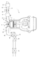
- FIG. 1 is a configuration explanatory view of an internal combustion engine 1 for automobiles in which a catalytic converter according to an embodiment of the present invention is used.
- the present invention is applied as a catalytic converter for an internal combustion engine for power generation that drives a generator in a series hybrid vehicle.
- the internal combustion engine 1 is intermittently operated in response to a power generation request from the vehicle side.
- the present invention is not limited to the internal combustion engine of a series hybrid vehicle, but can be applied to the internal combustion engine of a parallel hybrid vehicle or the internal combustion engine of a vehicle that simply travels with the output of the internal combustion engine.
- the internal combustion engine 1 is, for example, a spark-ignition internal combustion engine having a 4-stroke cycle.
- a pair of intake valves 4 and a pair of exhaust valves 5 are arranged on the ceiling wall surface of the combustion chamber 3, and these intake valves 4 are arranged.
- the spark plug 6 is arranged in the central portion surrounded by the exhaust valve 5.
- a fuel injection valve 16 for in-cylinder injection that directly injects fuel into the combustion chamber 3 is arranged as a main fuel injection valve. Further, the intake port 15 is provided with a port injection fuel injection valve 12 for injecting fuel into the intake port 15 as an auxiliary fuel injection valve that operates under specific conditions for each cylinder.
- the in-cylinder injection fuel injection valve 16 and the port injection fuel injection valve 12 are both electromagnetic or piezoelectric injection valves that open when a drive pulse signal is applied, and are of the drive pulse signal. The amount of fuel injected is substantially proportional to the pulse width.
- a configuration may include only one of the in-cylinder injection fuel injection valve 16 and the port injection fuel injection valve 12.
- An electronically controlled throttle valve 19 whose opening degree is controlled by a control signal from an engine controller (not shown) is interposed on the upstream side of the collector portion 18 of the intake passage 14 connected to the intake port 15.
- An air flow meter 20 for detecting the amount of intake air is arranged on the upstream side of the throttle valve 19, and an air cleaner 21 is arranged on the further upstream side.
- a pre-catalytic converter 26 is provided in the exhaust passage 25 connected to the exhaust port 17, and the main catalytic converter 27 is arranged on the downstream side of the pre-catalytic converter 26. There is.
- An air-fuel ratio sensor 28 for detecting the air-fuel ratio is arranged on the upstream side of the pre-catalytic converter 26.
- the pre-catalytic converter 26 is located relatively upstream of the exhaust system and is housed in the engine compartment of the vehicle.
- the main catalytic converter 27 is arranged under the floor of the vehicle.
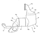
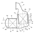
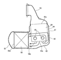
- FIG. 2 is a side view of the pre-catalytic converter 26 of one embodiment (hereinafter, simply referred to as a catalytic converter 26), and FIG. 3 is a cross-sectional view showing the internal configuration thereof.
- the catalytic converter 26 has an inlet side diffuser 51 connected to an upstream exhaust passage (for example, an outlet of an exhaust manifold assembly) and an outlet diffuser connected to a downstream exhaust passage.
- an upstream exhaust passage for example, an outlet of an exhaust manifold assembly
- an inner liner 54 provided in a part of the case 53 so as to form a double pipe structure, and a case 53.
- the first catalyst 55 and the second catalyst 56 which are arranged in a columnar shape, are provided.
- the inlet side diffuser portion 51 has a shape in which the diameter gradually expands from the exhaust pipe portion 51a to a circular large diameter portion 51b having a relatively large diameter, and the outlet side diffuser portion 52 has a circular shape.
- the diameter is tapered from the large diameter portion 52a to the exhaust pipe portion 52b.
- a branch pipe 57 for the EGR passage is connected to the exhaust pipe portion 52b.
- the large diameter portion 51b of the inlet side diffuser portion 51 and the large diameter portion 52a of the outlet side diffuser portion 52 have substantially the same diameter and are arranged in directions orthogonal to each other.
- the case 53 connects the inlet side diffuser portion 51 and the outlet side diffuser portion 52, and is bent in a substantially L shape.
- the case 53 has a cylindrical upstream cylindrical portion 61 having one end continuous with the large diameter portion 51b of the inlet side diffuser portion 51 and a cylindrical portion having one end continuous with the large diameter portion 52a of the outlet side diffuser portion 52. It has a downstream cylindrical portion 62, and the central axis L1 of the upstream cylindrical portion 61 and the central axis L1 of the downstream cylindrical portion 62 are orthogonal to each other.
- orthogonal does not mean that it is geometrically strictly "90 °", and for example, if it is about 85 ° to 95 °, it can be considered to be orthogonal.
- the upstream cylindrical portion 61 and the downstream cylindrical portion 62 are combined so as to form an L shape, and the end portion of the downstream cylindrical portion 62 opposite to the outlet side diffuser portion 52 is the upstream cylindrical portion 61. It is continuous with a part of the peripheral surface (a part in the circumferential direction) at the end portion opposite to the inlet side diffuser portion 51 via a pair of crescent-shaped portions 62a.
- the diameter of the upstream cylindrical portion 61 is slightly larger than the diameter of the large diameter portion 51b of the inlet side diffuser portion 51, and the upstream cylindrical portion 61 is connected to the inlet side diffuser portion 51 via the annular tapered portion 61a.
- the downstream cylindrical portion 62 has a diameter substantially equal to that of the large diameter portion 52a of the outlet side diffuser portion 52, and the outlet side diffuser portion 52 is connected to the end portion of the downstream cylindrical portion 62 extending linearly.
- the diameter of the upstream cylindrical portion 61 is slightly larger than the diameter of the downstream cylindrical portion 62. Therefore, the crescent-shaped portion 62a is connected to an angle range smaller than 180 ° in the peripheral surface of the upstream cylindrical portion 61.
- the end portion of the upstream cylindrical portion 61 opposite to the inlet side diffuser portion 51 is closed by a bottom wall portion 63 that diagonally intersects the central axis L1.
- the peripheral surface of the end portion of the upstream cylindrical portion 61 is smoothly continuous with the downstream cylindrical portion 62 via the bottom wall portion 63, except for the portion occupied by the crescent-shaped portion 62a. ..
- the portion including the upstream cylindrical portion 61 and the crescent-shaped portion 62a and the linear portion of the downstream cylindrical portion 62 are molded as separate parts, and both are assembled integrally.
- the case 53 is integrally molded as one component or divided into appropriate plurality of parts.
- the inner liner 54 has a cylindrical shape having a diameter corresponding to the large diameter portion 51b of the inlet side diffuser portion 51, and is supported by fixing one end to the upstream end portion of the upstream cylindrical portion 61 of the case 53. .. Specifically, one end of the inner liner 54 is fixed to the end of the tapered portion 61a connected to the large diameter portion 51b of the inlet side diffuser portion 51 on the small diameter portion side.
- the large diameter portion 51b of the inlet side diffuser portion 51 overlaps the inner peripheral surface of the tapered portion 61a
- the end portion of the inner liner 54 overlaps the inner peripheral surface of the inlet side diffuser portion 51.
- the inlet side diffuser portion 51 and the upstream side cylindrical portion 61 may be integrally formed as one component, or the inlet side diffuser portion 51 and the inner liner 54 may be integrally formed as one component. ..
- the other end of the inner liner 54 is open toward the bottom wall portion 63 as a free end in the case 53.
- the central axis of the inner liner 54 coincides with the central axis L1 of the upstream cylindrical portion 61. Therefore, a so-called double pipe structure is formed by the inner liner 54 and the upstream cylindrical portion 61, and a gap serving as an annular flow path 64 exists between the two.
- the tip of the inner liner 54 is separated from the bottom wall portion 63, so that the annular flow path 64 communicates with the space created between the tip of the inner liner 54 and the bottom wall portion 63.
- the flow path cross-sectional area of the annular flow path 64 (the cross-sectional area in the cross section orthogonal to the central axis L1) is constant along the axial direction of the inner liner 54.
- the distance between the inner liner 54 and the upstream cylindrical portion 61 is constant in each portion.
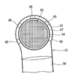
- a plurality of (for example, five) support members 65 having thermal conductivity are arranged between the peripheral surface of the tip end portion of the inner liner 54 and the upstream cylindrical portion 61.
- the support member 65 is formed by forming a metal mesh in a columnar or disk shape, and therefore can be elastically deformed and has vibration damping properties.
- the support member 65 is located near the tip edge of the inner liner 54 and is arranged at a plurality of locations (for example, five locations) in the circumferential direction (see FIG. 4). By locating the support members 65 at a plurality of points, vibration of the tip portion of the inner liner 54, which is a free end, is suppressed.
- the first catalyst 55 is formed by supporting a catalyst material (for example, a three-way catalyst) as a coating layer on a cylindrical upstream ceramic member serving as a catalyst carrier in which a large number of fine passages are formed along the axial direction, and is an inner liner. It is held inside the 54 via a cushioning mat member 67.
- the first catalyst 55 is a general three-way catalyst using a so-called monolith catalyst carrier.
- the end face 55a on the downstream side (that is, the outlet side) of the first catalyst 55 is at a position that matches the position of the tip edge of the inner liner 54.
- the end face 55b on the upstream side (that is, the inlet side) of the first catalyst 55 is located at a position corresponding to the proximal edge of the inner liner 54. That is, the total length of the first catalyst 55 is substantially equal to the total length of the inner liner 54.
- the upstream end face 55b is located adjacent to the inlet side diffuser portion 51, and the inlet side diffuser portion 51 is configured to cover the end face 55b.
- a catalyst material for example, a three-way catalyst
- a catalyst material is coated on a cylindrical downstream ceramic member that forms a large number of fine passages along the axial direction and alternately seals the ends of these fine passages. It is a fine particle collection filter supported as a layer.
- the second catalyst 56 is a general GPF (gasoline particulate filter) in which a catalyst material is supported on a so-called seal-type monolith catalyst carrier. A fine particle collection filter that does not support a catalyst material may be used.
- the second catalyst 56 is held inside the downstream cylindrical portion 62 via a cushioning mat member 68.
- the total length of the second catalyst 56 is basically equal to the length of the linear portion of the downstream cylindrical portion 62.
- the end surface 56a on the downstream side (that is, the outlet side) of the second catalyst 56 is located adjacent to the outlet side diffuser portion 52, and the outlet side diffuser portion 52 is configured so as to cover the end surface 56a.
- the end surface 56b on the upstream side (that is, the inlet side) of the second catalyst 56 is located near the boundary between the linear portion and the crescent-shaped portion 62a of the downstream cylindrical portion 62, and is open in the case 53. ..
- the diameters of the first catalyst 55 and the second catalyst 56 are substantially the same, and the axial lengths of the first catalyst 55 and the second catalyst 56 are also substantially the same.
- the end face 56b on the upstream side of the second catalyst 56 faces the peripheral surface of the inner liner 54, and more than half of the diameter of the end face 56b overlaps with the peripheral surface of the inner liner 54. That is, in FIG. 3, the radial dimension of the region of the end face 56b projecting downward from the tip edge of the inner liner 54 is smaller than the radius of the second catalyst 56. Between the end surface 56b of the second catalyst 56 and the peripheral surface of the inner liner 54, there is a gap (that is, a distance between the inner liner 54 and the upstream cylindrical portion 61) which is a flow path 64 in the above-mentioned double pipe structure. There are similar or slightly larger intervals.
- the catalyst converter 26 configured in this way, after the exhaust gas from the exhaust manifold passes through the first catalyst 55, the flow direction is changed in the case 53 and the second catalyst 56 is passed through, and the main under the vehicle floor. It will go to the catalytic converter 27.
- the catalysts 55 and 56 are cooled by the outside air.
- the first catalyst 55 receives a heat insulating action or a heat retaining action because the inner liner 54 and the upstream cylindrical portion 61 form a so-called double tube structure and there is a gap serving as a flow path 64 between the two.
- the temperature drop due to the vehicle running wind while the internal combustion engine 1 is stopped becomes slow. Therefore, the next time the operation of the internal combustion engine 1 is started, the catalytic action is obtained relatively early.
- the temperature of the first catalyst 55 located on the upstream side tends to rise.
- an excessive temperature rise is likely to occur at the tip of the first catalyst 55, which is a free end.
- the heat of the first catalyst 55 is transferred to the case 53 via the support member 65 having thermal conductivity. Therefore, an excessive temperature rise at the tip portion of the first catalyst 55, which tends to rise in temperature, is suppressed. As a result, the thermal deterioration of the first catalyst 55 is suppressed.
- a part of the exhaust gas exiting the end surface 55a on the downstream side of the first catalyst 55 flows along the bottom wall portion 63 to the second catalyst 56.
- a part of the air flows in the annular flow path 64 between the inner liner 54 and the upstream cylindrical portion 61 in the axial and circumferential directions (that is, along a spiral shape) and flows into the second catalyst 56. .. Therefore, even in the region of the second catalyst 56 that overlaps the peripheral surface of the inner liner 54, the exhaust gas that has passed through the first catalyst 55 flows smoothly. Therefore, the exhaust gas is widely dispersed on the end surface 56b of the second catalyst 56, and the exhaust gas is relatively less biased locally.
- the exhaust gas is surely guided to the overlapping portion of the end face 56b of the second catalyst 56 with the inner liner 54 via the annular flow path 64 having the double pipe structure, so that the end face 56b and the inner liner 54 It is possible to set the overlap relatively large. As described above, even if more than half of the diameter of the end face 56b of the second catalyst 56 overlaps with the inner liner 54, a sufficiently smooth exhaust flow can be obtained. In one embodiment, the overlap is about 60-70% of the diameter of the end face 56b. By setting the overlap to be large in this way, the external dimensions of the catalytic converter 26 (particularly the vertical dimensions in FIG. 3) can be miniaturized.
- annular flow path 64 is formed with an even width over the entire circumference of the inner liner 54, a relatively large flow path breakage can be achieved by setting the diameter of the upstream cylindrical portion 61 to be slightly larger than that of the inner liner 54. The area can be obtained. Therefore, it is possible to ensure a smooth exhaust flow to the second catalyst 56 while making the external dimensions of the catalyst converter 26 (particularly the external dimensions of the upstream cylindrical portion 61) relatively small.
- the support member 65 of the above embodiment has a circular outer shape in the flow path 64, the exhaust flow is not impaired.
- the shape of the support member 65 is not limited to the circular shape shown in the figure, and various other shapes are possible.
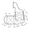
- FIG. 6 shows the central axis L1 of the upstream cylindrical portion 61 so as to follow the flow of exhaust gas flowing through the flow path 64 from the end surface 55a of the first catalyst 55 to the end surface 56b of the second catalyst 56.
- the slanted elongated support member 65 is shown.
- the support member 65 is formed by forming a metal mesh having thermal conductivity in the shape of an elongated rod.
- the support member 65 provided on the side opposite to the peripheral surface portion shown in FIG. 6 is inclined so as to be symmetrical with the support member 65 shown in FIG.
- the support member 65A located on the peripheral surface opposite to the end surface 56b of the second catalyst 56 can be arranged so as to be parallel to the central axis L1.
- the bead portion 69 in which the upstream cylindrical portion 61 bulges outward at a position slightly upstream from the axial position of the inner liner 54 in which the plurality of support members 65 are arranged side by side. have.
- the bead portion 69 is continuously formed in the circumferential direction of the upstream cylindrical portion 61, and is located adjacent to the end portion of the support member 65.
- the flow path cross-sectional area of the annular flow path 64 (the cross-sectional area in the cross section orthogonal to the central axis L1) is partially expanded. This offsets the increase in passage resistance due to the presence of the support member 65 in the flow path 64.
- the first catalyst 55 is configured as one monolith catalyst, but it may be divided into a plurality of monolith catalysts.
- a front-stage catalyst and a rear-stage catalyst having different characteristics can be arranged in series, and both can be housed in the inner liner 54.
- a configuration in which the second catalyst 56 is divided into a plurality of parts is also possible.
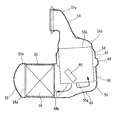
- FIG. 7 shows the catalyst converter 26 of the second embodiment in which the electric heating type catalyst (EHC) 71 is provided between the inlet side diffuser portion 51 and the first catalyst 55.
- the electroheating catalyst 71 has a columnar shape having a relatively short axial dimension, that is, a flat disk shape, and is arranged so as to be arranged in series with the first catalyst 55 on the upstream side of the first catalyst 55.
- the electrically heating type catalyst 71 various types of catalysts can be applied. For example, a metal catalyst carrier coated with a catalyst material and configured to generate heat when energized is used. In the illustrated example, the electrically heated catalyst 71 is held inside the inner liner 54 together with the first catalyst 55 via a mat member 72.
- the inner liner 54 has a so-called single-tube structure in the portion where the electric heating catalyst 71 is housed, and is exposed to the outside without being covered by the upstream cylindrical portion 61 constituting the annular flow path 64.
- the tapered portion 61a which is the end of the upstream cylindrical portion 61, is located near the boundary between the electrically heated catalyst 71 and the first catalyst 55.
- the electric heating type catalyst 71 does not become unnecessarily high temperature. Further, it becomes easy to pull out a connector or the like (not shown) for supplying electricity to the electrically heated catalyst 71 to the outside.
- the first catalyst 55 is compared with the first embodiment shown in FIGS. 3 and 4.
- the axial dimension of is smaller.
- it may be combined with the first catalyst 55 having the same size as the first catalyst 55 of FIGS. 3 and 4.
Landscapes
- Engineering & Computer Science (AREA)
- Chemical & Material Sciences (AREA)
- Chemical Kinetics & Catalysis (AREA)
- Combustion & Propulsion (AREA)
- General Engineering & Computer Science (AREA)
- Mechanical Engineering (AREA)
- Health & Medical Sciences (AREA)
- Toxicology (AREA)
- Biomedical Technology (AREA)
- Environmental & Geological Engineering (AREA)
- Analytical Chemistry (AREA)
- General Chemical & Material Sciences (AREA)
- Oil, Petroleum & Natural Gas (AREA)
- Ceramic Engineering (AREA)
- Materials Engineering (AREA)
- Exhaust Gas After Treatment (AREA)
Priority Applications (5)
| Application Number | Priority Date | Filing Date | Title |
|---|---|---|---|
| PCT/IB2019/000566 WO2020234618A1 (ja) | 2019-05-22 | 2019-05-22 | 触媒コンバータ |
| EP19929204.6A EP3974628B1 (en) | 2019-05-22 | 2019-05-22 | Catalytic converter |
| JP2021520476A JP7159465B2 (ja) | 2019-05-22 | 2019-05-22 | 触媒コンバータ |
| US17/612,769 US11623180B2 (en) | 2019-05-22 | 2019-05-22 | Catalytic converter |
| CN201980096477.5A CN113906199B (zh) | 2019-05-22 | 2019-05-22 | 催化转化器 |
Applications Claiming Priority (1)
| Application Number | Priority Date | Filing Date | Title |
|---|---|---|---|
| PCT/IB2019/000566 WO2020234618A1 (ja) | 2019-05-22 | 2019-05-22 | 触媒コンバータ |
Publications (1)
| Publication Number | Publication Date |
|---|---|
| WO2020234618A1 true WO2020234618A1 (ja) | 2020-11-26 |
Family
ID=73458078
Family Applications (1)
| Application Number | Title | Priority Date | Filing Date |
|---|---|---|---|
| PCT/IB2019/000566 Ceased WO2020234618A1 (ja) | 2019-05-22 | 2019-05-22 | 触媒コンバータ |
Country Status (5)
| Country | Link |
|---|---|
| US (1) | US11623180B2 (enExample) |
| EP (1) | EP3974628B1 (enExample) |
| JP (1) | JP7159465B2 (enExample) |
| CN (1) | CN113906199B (enExample) |
| WO (1) | WO2020234618A1 (enExample) |
Cited By (1)
| Publication number | Priority date | Publication date | Assignee | Title |
|---|---|---|---|---|
| CN115943250A (zh) * | 2021-08-05 | 2023-04-07 | 马瑞利株式会社 | 废气处理装置 |
Families Citing this family (2)
| Publication number | Priority date | Publication date | Assignee | Title |
|---|---|---|---|---|
| WO2020145050A1 (ja) * | 2019-01-09 | 2020-07-16 | マレリ株式会社 | 排気ガス処理装置 |
| JP2025111026A (ja) * | 2024-01-17 | 2025-07-30 | トヨタ自動車株式会社 | 内燃機関の排気浄化装置 |
Citations (7)
| Publication number | Priority date | Publication date | Assignee | Title |
|---|---|---|---|---|
| JPH0725212U (ja) * | 1993-09-30 | 1995-05-12 | 株式会社小松製作所 | 内燃機関の排気ガス浄化装置 |
| JP2003049634A (ja) * | 2001-08-03 | 2003-02-21 | Calsonic Kansei Corp | 車両用パーティキュレートフィルタ |
| JP2011117409A (ja) * | 2009-12-07 | 2011-06-16 | Ngk Insulators Ltd | 排ガス処理装置 |
| JP2015098834A (ja) * | 2013-11-19 | 2015-05-28 | トヨタ自動車株式会社 | 内燃機関の触媒装置 |
| US20150330279A1 (en) * | 2014-05-15 | 2015-11-19 | GM Global Technology Operations LLC | External exhaust guiding flow chambers for multiple catalyst architecture |
| DE102016114283A1 (de) * | 2016-08-02 | 2018-02-08 | Benteler Automobiltechnik Gmbh | Abgasnachbehandlungsanordnung |
| JP2018096345A (ja) | 2016-12-16 | 2018-06-21 | マツダ株式会社 | エンジンの排気装置 |
Family Cites Families (18)
| Publication number | Priority date | Publication date | Assignee | Title |
|---|---|---|---|---|
| DE3524775C1 (de) * | 1985-07-11 | 1986-09-04 | Daimler-Benz Ag, 7000 Stuttgart | In einem metallenen Gehaeuse angeordneter monolithischer Abgaskatalysator |
| JPH06101465A (ja) * | 1992-09-22 | 1994-04-12 | Nissan Motor Co Ltd | 2重管触媒コンバータ |
| US5693295A (en) * | 1996-01-16 | 1997-12-02 | General Motors Corporation | Catalytic converter |
| JP3099733B2 (ja) * | 1996-05-09 | 2000-10-16 | 株式会社ディー・ビー・エス | 小型エンジン用排気ガス浄化装置 |
| US6713025B1 (en) * | 1999-09-15 | 2004-03-30 | Daimlerchrysler Corporation | Light-off and close coupled catalyst |
| JP2005264769A (ja) * | 2004-03-17 | 2005-09-29 | Nissan Motor Co Ltd | 内燃機関の触媒コンバータ |
| JP2007083189A (ja) * | 2005-09-22 | 2007-04-05 | Mazda Motor Corp | 触媒コンバータおよび排気システム |
| JP2009156071A (ja) * | 2007-12-25 | 2009-07-16 | Mitsubishi Motors Corp | 内燃機関の排気ガス浄化装置 |
| JP5032409B2 (ja) * | 2008-07-28 | 2012-09-26 | 三菱ふそうトラック・バス株式会社 | 排気浄化装置 |
| DE102009024718A1 (de) * | 2009-06-12 | 2010-12-16 | Emitec Gesellschaft Für Emissionstechnologie Mbh | Abgasbehandlungsvorrichtung für den motornahen Einsatz |
| DE102011075643A1 (de) * | 2011-05-11 | 2012-11-15 | J. Eberspächer GmbH & Co. KG | Abgasanlagenkomponente |
| EP2770177B1 (en) * | 2011-10-18 | 2018-01-31 | Toyota Jidosha Kabushiki Kaisha | Electrically heated catalyst |
| WO2013137105A1 (ja) * | 2012-03-13 | 2013-09-19 | 日産自動車株式会社 | 触媒コンバータ |
| JP2014031743A (ja) * | 2012-08-02 | 2014-02-20 | Bosch Corp | 内燃機関の排気浄化装置 |
| KR101379780B1 (ko) * | 2013-01-17 | 2014-04-04 | 가부시키가이샤 고마쓰 세이사쿠쇼 | 환원제 수용액 믹싱 장치 및 이것을 구비한 배기 가스 후처리 장치 |
| US9223715B2 (en) * | 2013-08-21 | 2015-12-29 | Via Alliance Semiconductor Co., Ltd. | Microprocessor mechanism for decompression of cache correction data |
| EP2960456B1 (en) * | 2014-06-27 | 2017-04-12 | Volvo Car Corporation | Angled and compact exhaust gas aftertreatment device |
| CN108571368B (zh) * | 2017-03-10 | 2020-06-16 | 马自达汽车株式会社 | 发动机的排气装置 |
-
2019
- 2019-05-22 US US17/612,769 patent/US11623180B2/en active Active
- 2019-05-22 EP EP19929204.6A patent/EP3974628B1/en active Active
- 2019-05-22 WO PCT/IB2019/000566 patent/WO2020234618A1/ja not_active Ceased
- 2019-05-22 CN CN201980096477.5A patent/CN113906199B/zh active Active
- 2019-05-22 JP JP2021520476A patent/JP7159465B2/ja active Active
Patent Citations (7)
| Publication number | Priority date | Publication date | Assignee | Title |
|---|---|---|---|---|
| JPH0725212U (ja) * | 1993-09-30 | 1995-05-12 | 株式会社小松製作所 | 内燃機関の排気ガス浄化装置 |
| JP2003049634A (ja) * | 2001-08-03 | 2003-02-21 | Calsonic Kansei Corp | 車両用パーティキュレートフィルタ |
| JP2011117409A (ja) * | 2009-12-07 | 2011-06-16 | Ngk Insulators Ltd | 排ガス処理装置 |
| JP2015098834A (ja) * | 2013-11-19 | 2015-05-28 | トヨタ自動車株式会社 | 内燃機関の触媒装置 |
| US20150330279A1 (en) * | 2014-05-15 | 2015-11-19 | GM Global Technology Operations LLC | External exhaust guiding flow chambers for multiple catalyst architecture |
| DE102016114283A1 (de) * | 2016-08-02 | 2018-02-08 | Benteler Automobiltechnik Gmbh | Abgasnachbehandlungsanordnung |
| JP2018096345A (ja) | 2016-12-16 | 2018-06-21 | マツダ株式会社 | エンジンの排気装置 |
Cited By (2)
| Publication number | Priority date | Publication date | Assignee | Title |
|---|---|---|---|---|
| CN115943250A (zh) * | 2021-08-05 | 2023-04-07 | 马瑞利株式会社 | 废气处理装置 |
| EP4382732A4 (en) * | 2021-08-05 | 2024-12-11 | Marelli Corporation | EXHAUST GAS TREATMENT DEVICE |
Also Published As
| Publication number | Publication date |
|---|---|
| EP3974628A1 (en) | 2022-03-30 |
| US11623180B2 (en) | 2023-04-11 |
| EP3974628B1 (en) | 2023-08-16 |
| JPWO2020234618A1 (enExample) | 2020-11-26 |
| CN113906199A (zh) | 2022-01-07 |
| US20220274060A1 (en) | 2022-09-01 |
| CN113906199B (zh) | 2023-11-28 |
| EP3974628A4 (en) | 2022-06-01 |
| JP7159465B2 (ja) | 2022-10-24 |
Similar Documents
| Publication | Publication Date | Title |
|---|---|---|
| US5408828A (en) | Integral cast diffuser for a catalytic converter | |
| JP6299856B1 (ja) | エンジンの排気装置 | |
| JP7159465B2 (ja) | 触媒コンバータ | |
| US10626781B2 (en) | Exhaust device of engine | |
| KR20030064630A (ko) | 엔진 배기가스 재순환 장치 | |
| CN110088442B (zh) | 发动机的排气装置 | |
| US10550750B2 (en) | Exhaust device of engine | |
| CN102482973A (zh) | 内燃机的排气净化装置 | |
| US20140007563A1 (en) | Multiple Skewed Channel Bricks Mounted In Opposing Clocking Directions | |
| JP6319412B1 (ja) | エンジンの排気装置 | |
| JP6729721B2 (ja) | エンジンの排気装置 | |
| US10557443B2 (en) | Exhaust device of engine | |
| JP2002285916A (ja) | 排気再循環装置 | |
| JP7693943B2 (ja) | 内燃機関の排気装置 | |
| JP2004084481A (ja) | 排気管 | |
| JP2025121617A (ja) | エンジンの排気システム | |
| JP2024011136A (ja) | 内燃機関の排気通路構造 | |
| US10323610B2 (en) | Noise attenuation device for an intake system of an internal combustion engine | |
| JP2025070259A (ja) | 内燃機関の排気管 | |
| JP4014121B2 (ja) | エンジンの排気ガス浄化装置 | |
| JP2002317627A (ja) | 排気ガス浄化装置 | |
| JP2018123786A (ja) | 排気ガス浄化装置 |
Legal Events
| Date | Code | Title | Description |
|---|---|---|---|
| 121 | Ep: the epo has been informed by wipo that ep was designated in this application |
Ref document number: 19929204 Country of ref document: EP Kind code of ref document: A1 |
|
| ENP | Entry into the national phase |
Ref document number: 2021520476 Country of ref document: JP Kind code of ref document: A |
|
| NENP | Non-entry into the national phase |
Ref country code: DE |
|
| ENP | Entry into the national phase |
Ref document number: 2019929204 Country of ref document: EP Effective date: 20211222 |