EP3973112B1 - Bodenreinigungsvorrichtung - Google Patents
Bodenreinigungsvorrichtung Download PDFInfo
- Publication number
- EP3973112B1 EP3973112B1 EP20810265.7A EP20810265A EP3973112B1 EP 3973112 B1 EP3973112 B1 EP 3973112B1 EP 20810265 A EP20810265 A EP 20810265A EP 3973112 B1 EP3973112 B1 EP 3973112B1
- Authority
- EP
- European Patent Office
- Prior art keywords
- cleaning
- cleaning head
- floor
- docking site
- head
- Prior art date
- Legal status (The legal status is an assumption and is not a legal conclusion. Google has not performed a legal analysis and makes no representation as to the accuracy of the status listed.)
- Active
Links
Images


Classifications
-
- E—FIXED CONSTRUCTIONS
- E03—WATER SUPPLY; SEWERAGE
- E03D—WATER-CLOSETS OR URINALS WITH FLUSHING DEVICES; FLUSHING VALVES THEREFOR
- E03D13/00—Urinals ; Means for connecting the urinal to the flushing pipe and the wastepipe; Splashing shields for urinals
- E03D13/005—Accessories specially adapted for urinals
-
- A—HUMAN NECESSITIES
- A47—FURNITURE; DOMESTIC ARTICLES OR APPLIANCES; COFFEE MILLS; SPICE MILLS; SUCTION CLEANERS IN GENERAL
- A47L—DOMESTIC WASHING OR CLEANING; SUCTION CLEANERS IN GENERAL
- A47L11/00—Machines for cleaning floors, carpets, furniture, walls, or wall coverings
- A47L11/28—Floor-scrubbing machines, motor-driven
-
- A—HUMAN NECESSITIES
- A47—FURNITURE; DOMESTIC ARTICLES OR APPLIANCES; COFFEE MILLS; SPICE MILLS; SUCTION CLEANERS IN GENERAL
- A47L—DOMESTIC WASHING OR CLEANING; SUCTION CLEANERS IN GENERAL
- A47L11/00—Machines for cleaning floors, carpets, furniture, walls, or wall coverings
- A47L11/40—Parts or details of machines not provided for in groups A47L11/02 - A47L11/38, or not restricted to one of these groups, e.g. handles, arrangements of switches, skirts, buffers, levers
- A47L11/4002—Installations of electric equipment
- A47L11/4008—Arrangements of switches, indicators or the like
-
- A—HUMAN NECESSITIES
- A47—FURNITURE; DOMESTIC ARTICLES OR APPLIANCES; COFFEE MILLS; SPICE MILLS; SUCTION CLEANERS IN GENERAL
- A47L—DOMESTIC WASHING OR CLEANING; SUCTION CLEANERS IN GENERAL
- A47L11/00—Machines for cleaning floors, carpets, furniture, walls, or wall coverings
- A47L11/40—Parts or details of machines not provided for in groups A47L11/02 - A47L11/38, or not restricted to one of these groups, e.g. handles, arrangements of switches, skirts, buffers, levers
- A47L11/4063—Driving means; Transmission means therefor
- A47L11/4069—Driving or transmission means for the cleaning tools
-
- A—HUMAN NECESSITIES
- A47—FURNITURE; DOMESTIC ARTICLES OR APPLIANCES; COFFEE MILLS; SPICE MILLS; SUCTION CLEANERS IN GENERAL
- A47L—DOMESTIC WASHING OR CLEANING; SUCTION CLEANERS IN GENERAL
- A47L11/00—Machines for cleaning floors, carpets, furniture, walls, or wall coverings
- A47L11/40—Parts or details of machines not provided for in groups A47L11/02 - A47L11/38, or not restricted to one of these groups, e.g. handles, arrangements of switches, skirts, buffers, levers
- A47L11/4091—Storing or parking devices, arrangements therefor; Means allowing transport of the machine when it is not being used
-
- E—FIXED CONSTRUCTIONS
- E03—WATER SUPPLY; SEWERAGE
- E03D—WATER-CLOSETS OR URINALS WITH FLUSHING DEVICES; FLUSHING VALVES THEREFOR
- E03D5/00—Special constructions of flushing devices, e.g. closed flushing system
- E03D5/10—Special constructions of flushing devices, e.g. closed flushing system operated electrically, e.g. by a photo-cell; also combined with devices for opening or closing shutters in the bowl outlet and/or with devices for raising/or lowering seat and cover and/or for swiveling the bowl
- E03D5/105—Special constructions of flushing devices, e.g. closed flushing system operated electrically, e.g. by a photo-cell; also combined with devices for opening or closing shutters in the bowl outlet and/or with devices for raising/or lowering seat and cover and/or for swiveling the bowl touchless, e.g. using sensors
-
- A—HUMAN NECESSITIES
- A47—FURNITURE; DOMESTIC ARTICLES OR APPLIANCES; COFFEE MILLS; SPICE MILLS; SUCTION CLEANERS IN GENERAL
- A47L—DOMESTIC WASHING OR CLEANING; SUCTION CLEANERS IN GENERAL
- A47L11/00—Machines for cleaning floors, carpets, furniture, walls, or wall coverings
- A47L11/24—Floor-sweeping machines, motor-driven
-
- A—HUMAN NECESSITIES
- A47—FURNITURE; DOMESTIC ARTICLES OR APPLIANCES; COFFEE MILLS; SPICE MILLS; SUCTION CLEANERS IN GENERAL
- A47L—DOMESTIC WASHING OR CLEANING; SUCTION CLEANERS IN GENERAL
- A47L11/00—Machines for cleaning floors, carpets, furniture, walls, or wall coverings
- A47L11/40—Parts or details of machines not provided for in groups A47L11/02 - A47L11/38, or not restricted to one of these groups, e.g. handles, arrangements of switches, skirts, buffers, levers
- A47L11/4011—Regulation of the cleaning machine by electric means; Control systems and remote control systems therefor
-
- A—HUMAN NECESSITIES
- A47—FURNITURE; DOMESTIC ARTICLES OR APPLIANCES; COFFEE MILLS; SPICE MILLS; SUCTION CLEANERS IN GENERAL
- A47L—DOMESTIC WASHING OR CLEANING; SUCTION CLEANERS IN GENERAL
- A47L11/00—Machines for cleaning floors, carpets, furniture, walls, or wall coverings
- A47L11/40—Parts or details of machines not provided for in groups A47L11/02 - A47L11/38, or not restricted to one of these groups, e.g. handles, arrangements of switches, skirts, buffers, levers
- A47L11/4036—Parts or details of the surface treating tools
-
- E—FIXED CONSTRUCTIONS
- E03—WATER SUPPLY; SEWERAGE
- E03D—WATER-CLOSETS OR URINALS WITH FLUSHING DEVICES; FLUSHING VALVES THEREFOR
- E03D13/00—Urinals ; Means for connecting the urinal to the flushing pipe and the wastepipe; Splashing shields for urinals
-
- E—FIXED CONSTRUCTIONS
- E03—WATER SUPPLY; SEWERAGE
- E03D—WATER-CLOSETS OR URINALS WITH FLUSHING DEVICES; FLUSHING VALVES THEREFOR
- E03D9/00—Sanitary or other accessories for lavatories ; Devices for cleaning or disinfecting the toilet room or the toilet bowl; Devices for eliminating smells
Definitions
- WO2013053712 for example describes a device for cleaning a standing surface for a urinal that includes a cassette-type insert that has a moveable standing surface for insertion in a recess in a floor below the urinal.
- a controllable drive device is provided for moving the standing surface past a cleaning device for cleaning the moveable standing surface.
- CN 1 09 296 042 A describes a self-cleaning toilet.
- the toilet comprises a toilet body and a self-cleaning system, the self-cleaning system comprises a cleaning device, and the cleaning device is movable arranged in the toilet body and used for moving to a to-be-cleaned area of the toilet body to clean the to-be-cleaned area.
- the self-cleaning toilet can clean the toilet body in time and solve the problems that the stink of toilets is strong and bacteria are generated.
- DE 10 2006 004 508 A1 describes a sanitary facility with an alternative floor cleaning system for automatically cleaning the sanitary facility floor
- the invention proposes a sanitary facility with a plate-shaped floor and a floor cleaning device, wherein floor and floor cleaning device carry out a relative movement while cleaning the floor.
- a cleaning system for cleaning a floor of a restroom and comprising a wall coupled cleaning head and a docking site.
- the cleaning head may be of a self-driving ability, which may be facilitated via a driving means such as a motor implemented within the cleaning head.
- the cleaning head may be movable via means other or in addition to self-driving - such as via an actuator or linear actuator, possibly with an integrated motor (such as an 'actuator and motor drive' and/or a 'linear belt driven actuator' available from various manufactures such as Macron Dynamics Inc. or the like).
- actuators may be coupled to the cleaning head coupling/connecting it to a wall of a restroom and may optionally be made to move along a rail (or the like) to urge movement of the cleaning head along a floor being cleaned together with tubes, pipes and the like required for its operation.
- the docking site may be arranged to at least partially house the cleaning head when not in use, wherein the cleaning head being permanently connected to electrical cables, water source and drain or the like and hydraulic and/or pneumatic hoses.
- FIG. 1 illustrating a top view of a restroom that includes several urinals 10 that are placed in a row along a front wall 12 to which the urinals are fitted.
- the restroom also includes in this example a side wall 14 that extends generally perpendicular to the front wall 12 at a side or the row of urinals.
- the restroom seen in this view includes an embodiment of a cleaning system 181 that is wall-coupled i.e. permanently connected to a wall of the restroom during all stages of use, possibly with assistance of a cable carrier or the like (not shown in the Fig.) for guiding and supplying a cleaning head 2601 of the system with necessary liquid, drainage, power (or the like) for its operation.
- a cleaning system 181 that is wall-coupled i.e. permanently connected to a wall of the restroom during all stages of use, possibly with assistance of a cable carrier or the like (not shown in the Fig.) for guiding and supplying a cleaning head 2601 of the system with necessary liquid, drainage, power (or the like) for its operation.
- the cleaning head may be of a self-driving ability for permitting the cleaning head movement back and forth along the floor of a restroom, here alongside the front wall to clean the floor below the urinals.
- Self-driven ability of a cleaning head may be facilitated in the various embodiments herein discussed by a driving means located within the head, such as an electric motor, that is arranged to drive the cleaning head possibly via wheels provide within the head along the floor.
- actuators may be coupled to a cleaning head for moving it along the floor (see, e.g., Figs. 3 and 4 illustrating scissor type actuators urging cleaning heads away and towards a wall of the restroom and/or see Fig. 8 ).
- Cleaning system 181 may be arranged to perform a cleaning action of the floor periodically or according to certain triggers, such as detection of liquid such as urine and/or other dirt on the floor beneath or in a vicinity of one or more of the urinals. Detection of movement e.g. or users in a vicinity of a urinal or toilet to be cleaned, may be another example of such trigger.
- a cleaning action by a cleaning head of such system may also include advancing the cleaning head to clean a certain region, e.g. beneath a certain urinal, and then 'parking' the cleaning head until demand for further cleaning is required.
- Such 'parking' of the cleaning head not necessarily within its docking site may limit disturbance to users of the restroom by e.g. avoiding/limiting movement of the head along the floor e.g. back to the docking site after completing a cleaning action of a certain region of the floor.
- Fig. 2 illustrating an embodiment of a cleaning system 182 generally similar to 181.
- the urinals have been removed to provide a better view of the cleaning system and its cleaning head 2602.
- a docking site 16 of the cleaning system may be provided where the cleaning head of system 182 may be housed when idle.
- docking site 16 is formed as a cavity within the side wall 14 where the cleaning system's head 2602 may be at least partially stored so it does not take up substantial space on the floor when not in use.
- Cleaning system 182 may include a rail 20 along which it's cleaning head may be guided to maneuver along the floor, where here rail 20 may be placed to extend along front wall 12.
- Rail 20 may be arranged to lead, move, support and/or guide flexible electrical cables and hydraulic and/or pneumatic hoses required for cleaning actions performed by its cleaning head (such as drainage, power and liquid supply, or the like).
- Such leading, moving, supporting and/or guiding may also or alternatively be facilitated by a cable carrier (such as carrier 71 later discussed) that may be designed to extend concealed within the restroom environment, such as at least partially concealed within one of the walls of the restroom.
- a cable carrier such as carrier 71 later discussed
- the cleaning system is seen including indicators 22 that may take form of flashing lights and/or sound indicators (or the like) for waring users of the restroom when in use.
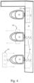
- FIG. 3 exemplifying an embodiment of a cleaning system 183, in this example several such systems 183 associated each with a respective urinal 10.
- Each cleaning system 183 may include a respective docking site 16 formed within the front wall 12, where each such docking site being arranged for housing the cleaning system's cleaning head when not in use.
- the cleaning heads may be wall-coupled i.e. connected to power, water, drain (or the like) required for their operation during their movements along the floor.
- the cleaning heads may be of a self-driving type or may be urged to move via actuators (see, e.g., scissor type actuators 99 indicated in Fig. 4 ).
- FIG. 4 illustrating the cleaning systems 183 of Fig. 3 during possible cleaning operations. While the cleaning system at the upper side of this figure is seen still housed within its docking site 16, the cleaning system 183 below it in this view is seen performing a cleaning action in a direction away from the front wall and the cleaning system 183 at the bottom of this figure is seen on route back towards its docking site.
- Cleaning system 183 may be arranged to provide support and/or guiding for flexible electrical cables and hydraulic and/or pneumatic hoses required for cleaning actions performed by its cleaning head (such as drainage, power and liquid supply or the like). Such support and/or guiding may also or alternatively be facilitated by a cable carrier (such as carrier 71 later discussed) that may be designed to extend towards the cleaning head of system 183 as it advances in its cleaning action.
- a cable carrier such as carrier 71 later discussed
- Each cleaning system 183 may be arranged to operate independently from other cleaning systems 183 and may be suited to clean a floor region immediately beneath the urinal it is arranged to service.
- a possible advantage of the arrangement seen in Fig. 3 and 4 may be that during each cleaning operation only a portion of the floor beneath the urinal being serviced may be occupied by the cleaning system thus permitting use of adjacent urinals during this time span.
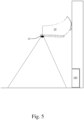
- FIG. 5 illustrating a side view of a urinal 10 within a restroom.
- a cleaning system 184 is seen including an optional sensor 24, possibly an optical and/or odor sensor, which is arranged to sense the floor region immediately beneath the urinal.
- Sensor 24 in this example is seen being fitted to the lower side of the urinal, however any other location suitable for permitting sensing of the floor may be chosen.
- such sensor may be fitted to the cleaning head (see, e.g. sensors 262 in Fig. 6 ).
- a controller of the cleaning system in communication with the sensor may be arranged to trigger a cleaning operation of the floor region by cleaning system 184 that may be generally similar to any one of the embodiments disclosed herein.
- FIG. 6 illustrating a bottom side of an embodiment of a cleaning head 26 that may be included in any one of the cleaning systems disclosed herein. It is noted that while cleaning head 26 here described is shown including a variety of utilities - embodiments suitable for the present disclosure may vary from the example here shown and/or may include only some of the utilities mentioned.
- Cleaning head 26 may be arranged to include utilities such as: wheels 261, sensors 262, dry and/or hot air vents 263, a dirt and water vacuum 264, wipers 265, a brush 266 and a secondary vacuum 267.
- Cleaning head 26 may be arranged to interact with and clean the floor of a restroom beneath one or more urinals, and may be arranged to receive and/or discharge liquids and/or fluids required or removed during a cleaning operation via suitable conduits from or towards its docking site.
- cleaning head 26 may be arranged to receive flexible electrical cables and hydraulic and/or pneumatic hoses required for cleaning actions that it performs (such as drainage, vacuum actions, dirt removal, power and liquid supply, or the like).
- Such flexible electrical cables and hydraulic and/or pneumatic hoses may be guided via a cable carrier 771 that provides wall-coupling of the cleaning head and extends towards one of the walls of the urinal and/or towards the docking site where the cleaning head is designed to dock when not in use.
- a controller may be provided within the cleaning head to control all cleaning actions and movements of the cleaning head, such as also sensors or communication with sensors within a cleaning system including cleaning head 26. Possibly, remote control of operations and/or monitoring of cleaning actions performed by the cleaning head may be provided via wire and/or via wireless communication such as via wifi (or the like).
Landscapes
- Engineering & Computer Science (AREA)
- Health & Medical Sciences (AREA)
- Public Health (AREA)
- Life Sciences & Earth Sciences (AREA)
- Hydrology & Water Resources (AREA)
- Water Supply & Treatment (AREA)
- Aviation & Aerospace Engineering (AREA)
- Epidemiology (AREA)
- Sanitary Device For Flush Toilet (AREA)
Claims (15)
- Reinigungssystem (181, 182, 183, 184, 185, 186) zum Reinigen eines Bodens einer Toilette und umfassend einen wandgekoppelten Reinigungskopf (26, 2601, 2602, 2605, 2606) und eine Andockstelle (16) zum mindestens teilweise Unterbringen des Reinigungskopfes, wenn nicht in Verwendung, bei welchem der Reinigungskopf wandgekoppelt ist durch permanentes Verbundensein mit einem von: elektrischen Kabeln, elektrischer Leistung, hydraulischen und/oder pneumatischen Schläuchen, hydraulischen und/oder pneumatischen Quellen,
dadurch gekennzeichnet, dass der Reinigungskopf angeordnet ist, um über Leitungen mit Anschlüssen der Andockstelle zu kommunizieren, um Fluide über solche Anschlüsse während der Verwendung, zum Beispiel während des Bewegens und Reinigens, zu empfangen und abzugeben, und wobei der Reinigungskopf ein Schmutz- und Wasservakuum (264, 267) umfasst, um beim Abgeben von Flüssigkeiten und/oder Fluiden während einer Reinigungsbetätigung über die Leitungen in Richtung der Andockstelle zu unterstützen. - Reinigungssystem nach Anspruch 1, bei welchem die Andockstelle innerhalb einer Wand der Toilette gebildet ist.
- Reinigungssystem nach Anspruch 1 oder 2 und mit einer gegebenen Sanitäreinrichtung in der Toilette assoziiert, um den Boden nur unterhalb der gegebenen Einrichtung zu reinigen, wobei die Andockstelle des Reinigungssystems in derselben Wand befindlich ist, wo die Sanitäreinrichtung angebracht ist, und angeordnet ist, um sich in eine Richtung weg von und in Richtung der Andockstelle zu bewegen, um den Boden unterhalb der gegebenen Sanitäreinrichtung zu reinigen.
- Reinigungssystem nach einem der Ansprüche 1 bis 2 und angeordnet, um den Boden unterhalb aller Sanitäreinrichtungen in der Toilette zu reinigen, wobei die Andockstelle des Reinigungssystems in einer Wand befindlich ist, im Allgemeinen quer zu der Wand, wo die Sanitäreinrichtungen angebracht sind.
- Reinigungssystem nach Anspruch 1 und umfassend einen oder mehrere Sensoren zum Detektieren des Vorhandenseins von zu reinigenden Substanzen an/auf dem Boden, wobei eine Reinigungsaktion bei Detektion von Substanzen durch den einen oder mehreren Sensoren ausgelöst wird.
- Reinigungssystem nach einem der Ansprüche 1 bis 5, bei welchem eine Reinigungsaktion periodisch ausgelöst wird.
- Reinigungssystem nach Anspruch 1, bei welchem eine Reinigungsaktion des Reinigungskopfes entlang einer Schiene des Systems durchgeführt wird, sich möglicherweise entlang einer Wand der Toilette erstreckend.
- Reinigungssystem nach Anspruch 1, bei welchem der Reinigungskopf selbstangetrieben ist und/oder angetrieben wird, um sich durch ein Aktuatormittel zu bewegen.
- Verfahren zum Reinigen eines Bodens einer Toilette, umfassend die Schritte:Bereitstellen eines Reinigungssystems (181, 182, 183, 184, 185, 186) umfassend einen wandgekoppelten Reinigungskopf (26, 2601, 2602, 2605, 2606) und eine Andockstelle (16) zum mindestens teilweise Unterbringen des Reinigungskopfes, wenn nicht in Verwendung,Drängen des Reinigungskopfes, sich zu bewegen und eine Reinigungsaktion des Bodens durchzuführen, wobei Wandkoppeln des Reinigungskopfes durch permanentes Verbundensein mit elektrischen Kabeln und Hydraulikschläuchen während Bewegungen erfolgt, wobeider Reinigungskopf angeordnet ist, um über Leitungen mit Anschlüssen der Andockstelle zu kommunizieren, um Flüssigkeiten über solche Anschlüsse während der Verwendung, zum Beispiel während des Bewegens und Reinigens, zu empfangen und abzugeben, und wobei der Reinigungskopf ein Schmutz- und Wasservakuum (264, 267) umfasst, um beim Abgeben von Flüssigkeiten und/oder Fluiden während einer Reinigungsbetätigung über die Leitungen in Richtung der Andockstelle zu unterstützen.
- Verfahren nach Anspruch 9, bei welchem nach Durchführen der Reinigungsaktion der Reinigungskopf in Richtung der Andockstelle zurückkehrt.
- Verfahren nach Anspruch 9, bei welchem nach Durchführen der Reinigungsaktion der Reinigungskopf zumindest für eine bestimmte Zeit nicht in der Andockstelle parkt.
- Verfahren nach einem der Ansprüche 9 bis 11 und angeordnet, um eine Anzeige bereitzustellen, wenn in Verwendung, möglicherweise eine visuelle und/oder akustische Anzeige.
- Verfahren nach einem der Ansprüche 9 bis 12, bei welchem der Reinigungskopf angeordnet ist, um eine beliebige der folgenden Aktionen während einer Reinigungsaktion durchzuführen: Vakuumieren von Luft und/oder Flüssigkeit, Wischen, Bürsten und/oder Trocknen des zu reinigenden Bodens.
- Verfahren nach einem der Ansprüche 9 bis 13 und umfassend einen oder mehrere Sensoren zum Erfassen eines zu reinigenden Bereichs, wobei die Sensoren innerhalb der Toilette und/oder an dem Reinigungskopf befindlich sind.
- Verfahren nach einem der Ansprüche 9 bis 14 und umfassend einen Controller zum Steuern mindestens einiger Betätigungen des Reinigungskopfs, wobei der Controller innerhalb des Reinigungskopfs befindlich ist.
Applications Claiming Priority (2)
| Application Number | Priority Date | Filing Date | Title |
|---|---|---|---|
| US201962849903P | 2019-05-19 | 2019-05-19 | |
| PCT/IB2020/054694 WO2020234748A1 (en) | 2019-05-19 | 2020-05-18 | Floor cleaning device |
Publications (4)
| Publication Number | Publication Date |
|---|---|
| EP3973112A1 EP3973112A1 (de) | 2022-03-30 |
| EP3973112A4 EP3973112A4 (de) | 2023-06-28 |
| EP3973112B1 true EP3973112B1 (de) | 2024-12-11 |
| EP3973112C0 EP3973112C0 (de) | 2024-12-11 |
Family
ID=73458081
Family Applications (1)
| Application Number | Title | Priority Date | Filing Date |
|---|---|---|---|
| EP20810265.7A Active EP3973112B1 (de) | 2019-05-19 | 2020-05-18 | Bodenreinigungsvorrichtung |
Country Status (3)
| Country | Link |
|---|---|
| US (1) | US11459743B2 (de) |
| EP (1) | EP3973112B1 (de) |
| WO (1) | WO2020234748A1 (de) |
Families Citing this family (2)
| Publication number | Priority date | Publication date | Assignee | Title |
|---|---|---|---|---|
| US12193620B1 (en) * | 2022-10-25 | 2025-01-14 | Regis Nziengui | Automated floor-cleaner for use in cleaning urine adjacent to a urinal |
| CN115744509B (zh) * | 2022-12-23 | 2024-09-24 | 亚洲富士电梯(临沂)有限公司 | 一种自动消毒清洗一体化的电梯信号控制方法 |
Family Cites Families (11)
| Publication number | Priority date | Publication date | Assignee | Title |
|---|---|---|---|---|
| JP2553631B2 (ja) * | 1988-05-13 | 1996-11-13 | 東陶機器株式会社 | 小便器の床清掃装置 |
| JP3166138B2 (ja) | 1992-10-27 | 2001-05-14 | 東陶機器株式会社 | 小便器清掃装置 |
| JPH0824164A (ja) | 1994-07-14 | 1996-01-30 | Masayuki Nakaya | 室内洗浄装置 |
| JP2005213785A (ja) * | 2004-01-28 | 2005-08-11 | Hiromu Imai | トイレ床清掃装置 |
| DE102006004508A1 (de) | 2006-02-01 | 2007-08-09 | Ströer Out-of-Home Media AG | Sanitäranlage mit einem Fußbodenreinigungssystem |
| DE102011084226B3 (de) | 2011-10-10 | 2012-12-27 | Nils Holger Seidel | Vorrichtung zum Reinigen der Trittfläche eines Urinals und entsprechende Urinalanordnung |
| CA2960113C (en) | 2016-03-31 | 2021-07-20 | The Boeing Company | Systems and methods for automatically cleaning a lavatory floor |
| US10793291B2 (en) * | 2016-03-31 | 2020-10-06 | The Boeing Company | Systems and methods for cleaning interior portions of a vehicle |
| US10006192B2 (en) * | 2016-07-13 | 2018-06-26 | Brian Arnott | Automatic floor cleaning machine and process |
| AU2018204467A1 (en) * | 2017-06-27 | 2019-01-17 | Bissell Inc. | Supply and/or disposal system for autonomous floor cleaner |
| CN109296042B (zh) | 2018-10-08 | 2020-09-22 | 深圳市微空间建筑科技有限公司 | 一种自清洁卫生间 |
-
2020
- 2020-05-18 US US17/611,378 patent/US11459743B2/en active Active
- 2020-05-18 WO PCT/IB2020/054694 patent/WO2020234748A1/en not_active Ceased
- 2020-05-18 EP EP20810265.7A patent/EP3973112B1/de active Active
Also Published As
| Publication number | Publication date |
|---|---|
| EP3973112A4 (de) | 2023-06-28 |
| US20220220718A1 (en) | 2022-07-14 |
| US11459743B2 (en) | 2022-10-04 |
| EP3973112A1 (de) | 2022-03-30 |
| WO2020234748A1 (en) | 2020-11-26 |
| EP3973112C0 (de) | 2024-12-11 |
Similar Documents
| Publication | Publication Date | Title |
|---|---|---|
| EP3973112B1 (de) | Bodenreinigungsvorrichtung | |
| CA2960250C (en) | Systems and methods for cleaning interior portions of a vehicle | |
| JP2019524402A (ja) | 自動床清掃機及び自動床清掃方法 | |
| CN103264682B (zh) | 智能洗车机 | |
| US20150053140A1 (en) | Modularly connected device for cleaning a pet toilet | |
| US6305034B1 (en) | Extensible and retractable urine deflecting apparatus for use with a toilet | |
| CA2337252A1 (en) | An unmanned vehicle adapted to be used in a stable, such as a cowshed | |
| US3969133A (en) | Method for self-cleaning a restroom | |
| JP2005213785A (ja) | トイレ床清掃装置 | |
| JP6134724B2 (ja) | 小便器の足場を洗浄するための装置および対応する小便器の構成 | |
| JP2002524094A (ja) | 乳牛等の動物の自動搾乳設備 | |
| CN217027336U (zh) | 一种公共厕所自动清洁装置 | |
| CZ31974U1 (cs) | Stacionární zařízení pro automatické čištění podlah místností | |
| JP2002143009A (ja) | 洗面化粧台 | |
| CN210813450U (zh) | 一种手术室外科消毒喷雾装置 | |
| JP2558055Y2 (ja) | トイレ洗浄装置 | |
| US20250129587A1 (en) | Self-cleaning toilet cleaner | |
| EA035637B1 (ru) | Санкабина самоочищающаяся | |
| CN220264869U (zh) | 一种家用梯自动厅门多门机控制装置 | |
| CN220283242U (zh) | 一种畜牧养殖运载电梯的排污系统 | |
| IT1292057B1 (it) | Dispositivo automatico di controllo del funzionamento delle spazzole di veicoli su ruote per la pulizia di pavimenti | |
| CN116551711A (zh) | 一种具有货仓状态监控功能的配送机器人 | |
| IT202300002598U1 (it) | Sistema di lavaggio automatizzato per allestimenti refrigerati mobili | |
| JP2521578Y2 (ja) | トイレ自動洗浄装置 | |
| JPH0621489U (ja) | 手洗機 |
Legal Events
| Date | Code | Title | Description |
|---|---|---|---|
| STAA | Information on the status of an ep patent application or granted ep patent |
Free format text: STATUS: THE INTERNATIONAL PUBLICATION HAS BEEN MADE |
|
| PUAI | Public reference made under article 153(3) epc to a published international application that has entered the european phase |
Free format text: ORIGINAL CODE: 0009012 |
|
| STAA | Information on the status of an ep patent application or granted ep patent |
Free format text: STATUS: REQUEST FOR EXAMINATION WAS MADE |
|
| 17P | Request for examination filed |
Effective date: 20211217 |
|
| AK | Designated contracting states |
Kind code of ref document: A1 Designated state(s): AL AT BE BG CH CY CZ DE DK EE ES FI FR GB GR HR HU IE IS IT LI LT LU LV MC MK MT NL NO PL PT RO RS SE SI SK SM TR |
|
| DAV | Request for validation of the european patent (deleted) | ||
| DAX | Request for extension of the european patent (deleted) | ||
| A4 | Supplementary search report drawn up and despatched |
Effective date: 20230601 |
|
| RIC1 | Information provided on ipc code assigned before grant |
Ipc: E03D 13/00 20060101ALI20230525BHEP Ipc: A47L 11/40 20060101ALI20230525BHEP Ipc: A47L 11/284 20060101ALI20230525BHEP Ipc: A47L 11/28 20060101ALI20230525BHEP Ipc: A47L 11/24 20060101ALI20230525BHEP Ipc: E03D 9/00 20060101AFI20230525BHEP |
|
| GRAP | Despatch of communication of intention to grant a patent |
Free format text: ORIGINAL CODE: EPIDOSNIGR1 |
|
| STAA | Information on the status of an ep patent application or granted ep patent |
Free format text: STATUS: GRANT OF PATENT IS INTENDED |
|
| INTG | Intention to grant announced |
Effective date: 20240807 |
|
| GRAS | Grant fee paid |
Free format text: ORIGINAL CODE: EPIDOSNIGR3 |
|
| GRAA | (expected) grant |
Free format text: ORIGINAL CODE: 0009210 |
|
| STAA | Information on the status of an ep patent application or granted ep patent |
Free format text: STATUS: THE PATENT HAS BEEN GRANTED |
|
| AK | Designated contracting states |
Kind code of ref document: B1 Designated state(s): AL AT BE BG CH CY CZ DE DK EE ES FI FR GB GR HR HU IE IS IT LI LT LU LV MC MK MT NL NO PL PT RO RS SE SI SK SM TR |
|
| REG | Reference to a national code |
Ref country code: GB Ref legal event code: FG4D |
|
| REG | Reference to a national code |
Ref country code: CH Ref legal event code: EP |
|
| REG | Reference to a national code |
Ref country code: IE Ref legal event code: FG4D |
|
| REG | Reference to a national code |
Ref country code: DE Ref legal event code: R096 Ref document number: 602020043059 Country of ref document: DE |
|
| U01 | Request for unitary effect filed |
Effective date: 20250110 |
|
| U07 | Unitary effect registered |
Designated state(s): AT BE BG DE DK EE FI FR IT LT LU LV MT NL PT RO SE SI Effective date: 20250117 |
|
| PG25 | Lapsed in a contracting state [announced via postgrant information from national office to epo] |
Ref country code: HR Free format text: LAPSE BECAUSE OF FAILURE TO SUBMIT A TRANSLATION OF THE DESCRIPTION OR TO PAY THE FEE WITHIN THE PRESCRIBED TIME-LIMIT Effective date: 20241211 |
|
| PG25 | Lapsed in a contracting state [announced via postgrant information from national office to epo] |
Ref country code: ES Free format text: LAPSE BECAUSE OF FAILURE TO SUBMIT A TRANSLATION OF THE DESCRIPTION OR TO PAY THE FEE WITHIN THE PRESCRIBED TIME-LIMIT Effective date: 20241211 |
|
| PG25 | Lapsed in a contracting state [announced via postgrant information from national office to epo] |
Ref country code: NO Free format text: LAPSE BECAUSE OF FAILURE TO SUBMIT A TRANSLATION OF THE DESCRIPTION OR TO PAY THE FEE WITHIN THE PRESCRIBED TIME-LIMIT Effective date: 20250311 |
|
| PG25 | Lapsed in a contracting state [announced via postgrant information from national office to epo] |
Ref country code: GR Free format text: LAPSE BECAUSE OF FAILURE TO SUBMIT A TRANSLATION OF THE DESCRIPTION OR TO PAY THE FEE WITHIN THE PRESCRIBED TIME-LIMIT Effective date: 20250312 |
|
| PG25 | Lapsed in a contracting state [announced via postgrant information from national office to epo] |
Ref country code: RS Free format text: LAPSE BECAUSE OF FAILURE TO SUBMIT A TRANSLATION OF THE DESCRIPTION OR TO PAY THE FEE WITHIN THE PRESCRIBED TIME-LIMIT Effective date: 20250311 |
|
| U20 | Renewal fee for the european patent with unitary effect paid |
Year of fee payment: 6 Effective date: 20250402 |
|
| PG25 | Lapsed in a contracting state [announced via postgrant information from national office to epo] |
Ref country code: SM Free format text: LAPSE BECAUSE OF FAILURE TO SUBMIT A TRANSLATION OF THE DESCRIPTION OR TO PAY THE FEE WITHIN THE PRESCRIBED TIME-LIMIT Effective date: 20241211 |
|
| PG25 | Lapsed in a contracting state [announced via postgrant information from national office to epo] |
Ref country code: PL Free format text: LAPSE BECAUSE OF FAILURE TO SUBMIT A TRANSLATION OF THE DESCRIPTION OR TO PAY THE FEE WITHIN THE PRESCRIBED TIME-LIMIT Effective date: 20241211 |
|
| PG25 | Lapsed in a contracting state [announced via postgrant information from national office to epo] |
Ref country code: IS Free format text: LAPSE BECAUSE OF FAILURE TO SUBMIT A TRANSLATION OF THE DESCRIPTION OR TO PAY THE FEE WITHIN THE PRESCRIBED TIME-LIMIT Effective date: 20250411 |
|
| PG25 | Lapsed in a contracting state [announced via postgrant information from national office to epo] |
Ref country code: SK Free format text: LAPSE BECAUSE OF FAILURE TO SUBMIT A TRANSLATION OF THE DESCRIPTION OR TO PAY THE FEE WITHIN THE PRESCRIBED TIME-LIMIT Effective date: 20241211 |
|
| PG25 | Lapsed in a contracting state [announced via postgrant information from national office to epo] |
Ref country code: CZ Free format text: LAPSE BECAUSE OF FAILURE TO SUBMIT A TRANSLATION OF THE DESCRIPTION OR TO PAY THE FEE WITHIN THE PRESCRIBED TIME-LIMIT Effective date: 20241211 |
|
| PLBE | No opposition filed within time limit |
Free format text: ORIGINAL CODE: 0009261 |
|
| STAA | Information on the status of an ep patent application or granted ep patent |
Free format text: STATUS: NO OPPOSITION FILED WITHIN TIME LIMIT |
|
| 26N | No opposition filed |
Effective date: 20250912 |