EP3972455B1 - Elektromotorische verstelleinheit zur neigungsverstellung eines stützteils eines sitzmöbels, stützteil und sitzmöbel - Google Patents
Elektromotorische verstelleinheit zur neigungsverstellung eines stützteils eines sitzmöbels, stützteil und sitzmöbel Download PDFInfo
- Publication number
- EP3972455B1 EP3972455B1 EP20724817.0A EP20724817A EP3972455B1 EP 3972455 B1 EP3972455 B1 EP 3972455B1 EP 20724817 A EP20724817 A EP 20724817A EP 3972455 B1 EP3972455 B1 EP 3972455B1
- Authority
- EP
- European Patent Office
- Prior art keywords
- unit
- motor
- support part
- adjusting unit
- seating furniture
- Prior art date
- Legal status (The legal status is an assumption and is not a legal conclusion. Google has not performed a legal analysis and makes no representation as to the accuracy of the status listed.)
- Active
Links
Images



Classifications
-
- A—HUMAN NECESSITIES
- A47—FURNITURE; DOMESTIC ARTICLES OR APPLIANCES; COFFEE MILLS; SPICE MILLS; SUCTION CLEANERS IN GENERAL
- A47C—CHAIRS; SOFAS; BEDS
- A47C7/00—Parts, details, or accessories of chairs or stools
- A47C7/36—Supports for the head or the back
- A47C7/38—Supports for the head or the back for the head, e.g. detachable
-
- A—HUMAN NECESSITIES
- A47—FURNITURE; DOMESTIC ARTICLES OR APPLIANCES; COFFEE MILLS; SPICE MILLS; SUCTION CLEANERS IN GENERAL
- A47C—CHAIRS; SOFAS; BEDS
- A47C7/00—Parts, details, or accessories of chairs or stools
- A47C7/36—Supports for the head or the back
- A47C7/40—Supports for the head or the back for the back
- A47C7/402—Supports for the head or the back for the back adjustable in height
-
- A—HUMAN NECESSITIES
- A47—FURNITURE; DOMESTIC ARTICLES OR APPLIANCES; COFFEE MILLS; SPICE MILLS; SUCTION CLEANERS IN GENERAL
- A47C—CHAIRS; SOFAS; BEDS
- A47C1/00—Chairs adapted for special purposes
- A47C1/02—Reclining or easy chairs
- A47C1/031—Reclining or easy chairs having coupled concurrently adjustable supporting parts
- A47C1/036—Reclining or easy chairs having coupled concurrently adjustable supporting parts the parts including a head-rest
-
- B—PERFORMING OPERATIONS; TRANSPORTING
- B60—VEHICLES IN GENERAL
- B60N—SEATS SPECIALLY ADAPTED FOR VEHICLES; VEHICLE PASSENGER ACCOMMODATION NOT OTHERWISE PROVIDED FOR
- B60N2/00—Seats specially adapted for vehicles; Arrangement or mounting of seats in vehicles
- B60N2/80—Head-rests
- B60N2/806—Head-rests movable or adjustable
- B60N2/838—Tiltable
- B60N2/853—Tiltable characterised by their adjusting mechanisms, e.g. electric motors
-
- B—PERFORMING OPERATIONS; TRANSPORTING
- B60—VEHICLES IN GENERAL
- B60N—SEATS SPECIALLY ADAPTED FOR VEHICLES; VEHICLE PASSENGER ACCOMMODATION NOT OTHERWISE PROVIDED FOR
- B60N2/00—Seats specially adapted for vehicles; Arrangement or mounting of seats in vehicles
- B60N2/80—Head-rests
- B60N2/806—Head-rests movable or adjustable
- B60N2/838—Tiltable
- B60N2/856—Tiltable movable to an inoperative or stowed position
-
- B—PERFORMING OPERATIONS; TRANSPORTING
- B60—VEHICLES IN GENERAL
- B60N—SEATS SPECIALLY ADAPTED FOR VEHICLES; VEHICLE PASSENGER ACCOMMODATION NOT OTHERWISE PROVIDED FOR
- B60N2/00—Seats specially adapted for vehicles; Arrangement or mounting of seats in vehicles
- B60N2/80—Head-rests
- B60N2/806—Head-rests movable or adjustable
- B60N2/838—Tiltable
- B60N2/856—Tiltable movable to an inoperative or stowed position
- B60N2/859—Tiltable movable to an inoperative or stowed position specially adapted for rear seats
Definitions
- the invention relates to an electromotive adjustment unit for adjusting the inclination of a support part of a piece of seating furniture according to the preamble of claim 1.
- the invention also relates to a piece of seating furniture and a supporting part of a piece of seating furniture.
- Seating furniture in particular upholstered armchairs or parts of an upholstered sofa, can have support parts that are adjustable in inclination. Headrests or armrests, for example, are used as support parts, which, due to their ability to adjust their inclination, allow the furniture to be adjusted ergonomically on the one hand and the design to be changed on the other.
- a comfortable adjustment can be achieved via an electromotive adjustment unit.
- Such electromotive adjustment units include at least one drive unit, which is usually designed as a linear drive and which acts via connecting rods and/or levers on the support part, which is pivotably connected to a body element, eg a back part, via a swivel fitting.
- the pamphlet shows DE 10 2013 200328 A1 such an adjustment unit, in which a headrest is pivoted by a linear actuator via an articulated lever chain.
- From the pamphlet KR 2003 0060284 A discloses an electromotive adjustment unit for adjusting the inclination of a support part of a piece of seating furniture, in particular a car seat, in which a drive unit, which includes a motor and a gear, is arranged in the adjustable support part itself.
- the drive unit has a rotatable output element which is fastened in a rotationally fixed manner to a holding bracket which connects the support part to the body element of the seating furniture item.
- the gear is designed as a reduction gear with a plurality of meshing gears.
- the pamphlet DE 10 2013 210 226 A1 shows a similar arrangement in which at least one gear stage is designed as a worm gear.
- WO 2011/037368 A2 is an electromotive adjustment unit for adjusting the inclination of a support part of a piece of seating furniture, in which the drive unit is arranged in the support part itself.
- This adjustment unit is also suitable for wider support parts, as there are two gears each with a rotatable output element, the output elements being non-rotatably attached to two different brackets that connect the support part to the body element of the chair.
- the two gearboxes are coupled to each other via a synchronous shaft and are driven together by a motor.
- An electromotive adjustment unit of the type mentioned at the outset has at least one retaining bracket for connection to a body element of the piece of seating furniture and a motor and gear unit as a drive unit with a mounting element for fastening the support part of the piece of seating furniture, the motor and gear unit having a rotatable output element which is non-rotatable is attached to the at least one headband.
- the motor and gear unit is therefore not arranged in the body element, but in the support part itself. It is connected to the support part and has a rotatable output element, which is then non-rotatably coupled to the body element via the retaining bracket mentioned. Correspondingly, two retaining brackets are required, with which the support part is attached to the body element in a manner similar to a manually adjustable support part.
- the body element can be a fixed element of the piece of seating furniture, for example a seat frame, or a movable element, such as a back part, for which the inclination of the support part is adjusted according to the invention.
- the motor and gear unit has a support bracket with a first leg, on which at least two meshing gears are mounted, which form a reduction gear, and a second leg, which is the mounting element.
- the high torques on the output element required for pivoting the support part can be achieved by the reduction gear.
- a bearing plate, in which the gears are also mounted, is preferably arranged parallel to the first leg of the support bracket.
- the output element is further preferably arranged or formed on one of the gears of the motor and transmission unit. The mounting of this (output) gear then advantageously also represents the pivot mounting of the support part.
- a gear wheel is also understood to mean a gear wheel segment that does not have teeth over the entire circumference, but only over a specific angular range.
- the gear on which the driven element is arranged or formed can be designed as a gear segment, since the pivoting angle of the driven element is generally less than 180° or often even less than 90°.
- a gear unit is also provided, which is coupled to the motor and gear unit via a synchronous shaft and which also has a rotatable output element which is fixed in a rotationally fixed manner to a further retaining bracket.
- the gear unit also has a support bracket with a first leg, on which at least two meshing gears are mounted, which form a reduction gear, and a second leg, which also represents a mounting element for the support part.
- the support part is pivotally mounted on one via the gear unit second side and on the other hand a synchronous drive of this second side.
- the adjustment unit is therefore particularly suitable for wider support parts.
- the reduction gear of the motor and gear unit and the reduction gear of the gear unit preferably have the same reduction ratio, the synchronous shaft being connected to an output shaft of a drive motor of the motor and gear unit.
- the same transmission ratio can be achieved in particular by having the two transmissions essentially the same design, so that advantageously as many of the same components as possible (gears, output element, bearing plate, etc.) can be used for the motor and transmission unit and the transmission unit, which reduces manufacturing and storage costs become.
- the output element engages in a form-fitting manner in a corresponding receptacle of the holding bracket.
- the required torques between the output element and the headband can be transmitted well and reliably due to the form fit, for example achieved by means of a toothing.
- the output element can be provided, for example, with an external spline, which is inserted into an opening with an internal spline, which is formed on the bracket.
- At least one of the retaining brackets is preferably hollow at least in sections, with a supply cable for the power supply being routed through the retaining bracket.
- at least one of the retaining brackets can consist of a conductive material, at least in sections, so that the power supply is provided by the retaining bracket itself.
- a connector can be provided on one or both of the retaining brackets, via which at least one pole of the power supply is routed. In this case, it is provided that the connector contacts a corresponding mating connector, which is plugged in starting from the body element or which is already integrated in the body element is, so that the electrical contact is automatically established when the retaining bracket is inserted.
- a support part of a piece of seating furniture according to the invention has such an electromotive adjustment unit and a piece of seating furniture according to the invention has at least one such support part.
- the support part is a head part, also called a headrest, of the chair. This can then be pivoted relative to a back part as a body element.
- the support part can also be an armrest, also called an armrest, which can then be pivoted relative to a side part as a body element.
- the body element itself can also be movable in relation to other parts of the seating furniture.
- a back part can have an inclination adjustment option and in turn carry the pivotable head part via the electromotive adjustment unit.
- the electromotive adjustment unit is preferably integrated into the support part in such a way that only sections of the at least one holding bracket protrude from an upholstery. Since all functional elements are in this way within of the support part, an existing support part that can only be adjusted manually or not at all can easily be exchanged for such an electrically adjustable support part, with the body element not needing to be modified or only minimally modified to accommodate power supply lines.
- the headband can take on a wide variety of shapes or consist of a wide variety of raw materials, for example round tubes or rectangular tubes are particularly suitable for this purpose.
- the headband is fixed to the body element by suitable connecting means, for example by screwing or by plugging into appropriate recordings.
- top, bottom, left, right refer exclusively to the exemplary representation selected in the respective figures.
- front and back refer to an orientation of the seating furniture related, wherein the front side of the chair is the side facing the user, on which there is also a seat for the user.
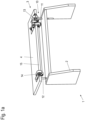
- Fig. 1a-c shows a section of an item of seating furniture 1 with a back part 2 and a head part 3, also called a headrest, which can be pivoted relative to this back part 2, in various views.
- the head part 3 thus represents a pivotable support element of the chair 1, which is mounted on the back part 2 as a body element.
- Fig. 1a shows the section of the chair 1 in an isometric view diagonally from the front
- Fig. 1b shows a front view and 1c a side view.
- the chair 1 is shown with a head part that is pivoted maximally backwards, ie away from the user.
- Fig. 2a-c give in same way as that Fig. 1a-c the section of the chair 1 again, but the head part 3 is maximally forward, ie pivoted in the direction of the user.
- the head part 3 is pivoted by an electric motor via an adjustment unit 10. According to the application, all active components of the adjustment unit 10 that lead to a movement, in particular a drive unit designed as a motor and gear unit, are arranged in the head part 3. Only one headboard 4 of the headboard 3 is shown as an example.
- the back part 2 is also only represented by panels connected to one another, which form a frame of the chair 1 . In the fully manufactured product, both the back part 2 and the head part 3 are provided with padding, which is attached to the panels shown of the back part 2 and the head part panel 4, respectively.
- the adjustment unit 10 is attached to the back part 2 with the aid of retaining brackets 11 , 12 .
- insertion openings are provided in the back part 2, into which the retaining brackets 11, 12 can be inserted.
- guide tubes can be incorporated into the back part 2, into which the retaining brackets 11, 12 are inserted.
- no components of the adjustment unit 10 are arranged in the back part 2, which is why the adjustment unit according to the application can also be used when there is no otherwise required space in the back part 2.
- the head part 3 with the adjustment unit 10 is well suited for retrofit solutions, since no or only minimal modifications to the back part 2 are necessary.
- the retaining brackets 11, 12 also have a function as part of an electrical power supply for the adjustment unit 10.
- power is supplied via only one of the retaining brackets, the retaining bracket 11, while the other retaining bracket 12 only has a supporting function. Details of the power supply on the headband or 11, 12 are in connection with the figure 5 and 6a-c explained in more detail.
- a motor and gear unit 13 is pivotably connected to the bracket 11 and a gear unit 14 is connected to the bracket 12.
- the motor and gear unit 13 is coupled to the gear unit 14 via a synchronous shaft 15, so that both units 13, 14 pivot synchronously during operation .
- FIG. 3a-c the adjustment unit is shown in the same view and with the same pivoting angle as in FIGS Fig. 2a-c .
- the Fig. 3a-c thus show the adjustment unit 10 before the connection to the headboard 4 and the back section 2.
- FIG 4 the adjustment unit 10 is reproduced in an isometric exploded view, the viewing angle and the adjustment angle corresponding to those of Figure 3a are equivalent to.
- the structure of the adjusting unit 10 is described below with reference to FIG Figures 3a-3c and 4 explained in more detail.
- the motor and gear unit 13 and the gear unit 14 of the adjustment unit 10 each have a support bracket 131 and 141, respectively.
- the support angle 131, 141 is preferably a sheet metal angle that has been created in a stamping and bending process.
- One leg in each case serves as a mounting element 132 or 142 to which the head part plate 4 is fastened, for example with screws.
- the motor and gear unit 13 and the gear unit 14 are in the plane of the head part plate 4, which has corresponding recesses 41 and 42. This arrangement of the headboard 4 in relation to the engine and Gear unit 13 or gear unit 14, the motor and gear unit 13 and the gear unit 14 are positioned centrally in the head part 3, as a result of which they can be cushioned particularly well by surrounding padding.
- openings on the other leg for receiving stub axles of gears 135 and 145 are formed on the support brackets 131, 141.
- the support brackets 131, 141 thus serve to support the gear wheels 135, 145.
- a bearing plate 133, 143 is provided on an opposite side of the gear wheels 135, 145, which has corresponding mirror-symmetrical bores in order to mount the gear wheels 135, 145 on the support bracket 131 , 141 opposite side to store.
- the bearing plates 133, 143 are arranged parallel to the support brackets 131, 141 by means of spacer elements (not designated in more detail in the figures) and are fastened to the support brackets 131, 141 via the spacer elements.
- one of the gear wheels has an output element 136, 146 which protrudes outwards through the support bracket 131, 141 and which is connected in a rotationally fixed manner to the respective holding bracket 11, 12.
- an internal spline 114, 124 is formed in the holding brackets 11, 12, in which the driven element 136, 146 engages.
- the output element 136, 146 is provided with a suitable toothing.
- the output members 136, 146 and the corresponding gear 135, 145 which carries the output member 136, 146 are non-rotatably connected to the brackets 11, 12.
- a combination of rivet and washer 115, 125 is provided in each case, which also connects the driven element 136, 146 or the associated gear wheel 135, 145 in the axial direction to the respective holding bracket 11, 12.
- the output element 136, 146 and the associated gear wheel 135, 145 are provided with a continuous axial bore for this purpose.
- a combination of screw and (locked or self-locking) nut can also be used.
- the gears 135 and 145 shown each form a reducing gear for the high torques required for pivoting the head part 3 to provide at the output element 136, 146.
- a housing shell 134, 144 is used in each case to cover the transmission thus formed.
- the transmission has a three-stage structure, with a drive gear, an intermediate gear and the already mentioned output gear, which is coupled to the output element 136, 146 or is manufactured in one piece with it.
- the drive gears are driven by a drive motor, which in turn is designed as a geared motor 137 in the present example.
- the transmission of the geared motor 137 can be a worm gear, for example, with a worm being arranged on an electric motor and acting on a worm wheel mounted on an output shaft 138 .
- the worm gear of the geared motor 137 can be designed in such a way that it is self-locking, so that the head part 3 does not pivot when the geared motor 137 is not energized, even when an external force is applied.
- a design can also be selected which is self-locking when moderate force is applied when used properly, but which leads to pivoting of the head part 3 when excessively strong external forces are applied. This counteracts damage to the adjustment unit 10 or its attachment to the back part 2 or the head part 3 .
- the output shaft 138 protrudes from the geared motor 137 on both sides. On one side, the output shaft 138 is coupled directly to the drive gear of the gears 135 of the engine and transmission unit 13 . The opposite part of the output shaft 138 is initially connected in a rotationally fixed manner to the synchronizing shaft 15 , which drives the drive gearwheel of the gearwheels 135 of the transmission unit 14 in a rotationally fixed manner. This ensures that both support brackets 131, 141 move synchronously when the geared motor 137 is actuated. To this end, pairs of identical gears 135, 145 are advantageously used in the motor and transmission unit 13 on the one hand and in the transmission unit 14 on the other.
- a limit switch plate 139 is also arranged, which has limit switches that are actuated when the support bracket 131 is one of the two end positions, which are also in the Fig. 1a-c or. 2a-c are shown, achieved.
- cams can be arranged at suitable positions on one of the gearwheels 135.
- the retaining bracket 11 is the in 4 shown adjusting unit 10 enlarged.
- the retaining clip 11 (just like the retaining clip 12) is inserted into a corresponding receptacle in the back part 2.
- the retaining bracket 11 has an insertion section 111, which has a slightly smaller diameter than the following support section 112. This is angled in the example shown.
- a particularly straight or only slightly angled shape of the support section 112 can also be selected here.
- a carrier lug 113 At the free end of the carrier section 112 there is a carrier lug 113 in which the already described internal multi-tooth 114 is formed.
- the retaining bracket 11 shown can be made entirely of tubular material in one piece in a stamping and bending process.
- the power supply for the geared motor 137 of the adjusting unit 10 takes place via the retaining bracket 11 .
- the transition area between the carrier section 112 and the carrier lug 113 there is an opening 116 through which the supply cable 117 coming from the geared motor 137 or the limit switch plate 139 is inserted into the carrier section 112 .
- a plug connector 118 is arranged at the opposite end of the plug-in section 111 and is connected to the supply cable 117 .
- the connector 118 makes contact with a corresponding mating connector, which is attached starting from the back part 2 or which is already integrated in the back part 2, so that when the retaining bracket 11 is inserted, the connector 118 automatically makes direct contact with the mating connector.
- the connector 118 can be designed with multiple poles, so that the two minimum required poles for supplying the geared motor 137 can be contacted via the connector 118 .
- the plug connector 118 can also have a single pole, with the at least one other required pole being routed via the plug-in section 111 .
- the holding bracket 11 is made of a metal pipe by a stamping and bending process
- the insertion portion 111 is also made of metal and is conductive so that it can serve as a conductor. Since the geared motor 137 is supplied with non-hazardous extra-low voltage as a low-voltage motor, it is not a problem that the entire headband 11 is at a potential that is also present at the geared motor 137 .
- the supply cable 117 is laid completely in one holding bracket 11 .
- the second retaining bracket 12 has no electrical functionality with an otherwise identical structure. However, it also has an insertion section 121, a carrier section 122 and a carrier lug 123, in which the internal spline 124 is formed (cf. 4 ).
- each of the holding brackets 11, 12 performs a function in the electrical power supply.
- each of the retaining brackets 11, 12 is used as a conductor over which one pole of the at least two poles required to supply the geared motor 137 is guided.
- a voltage difference, which is then present between the retaining brackets 11, 12 when the geared motor 137 is in operation, is also safe in this case, since the geared motor 137 is only supplied with low voltage.
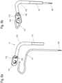
- FIG. 6a-c a second exemplary embodiment of a holding bracket 11 with a feed function is shown.
- Figure 6a shows the holding bracket 11 and the supply cable 117 to be inserted into it in isometric representations separately from one another.
- Both Figure 6b and 6c the supply cable 117 is inserted into the holding bracket 11.
- the Figure 6b shows the headband 11 again in an isometric view, whereas the Figure 6c shows the headband 11 in a sectional view.
- the headband 11 is different Fig. 6a-c that the plug-in section 111 is not connected to a connector 118 formed integrally with the holding bracket 11, but that the supply cable 117 leaves the tubular plug-in section 111 downwards and ends, for example, in a cable end 119, which can then be contacted by suitable clamps.
- the supply cable 117 can, of course, also be designed to be correspondingly longer, so that it can be routed through the seating furniture item 1 without any intermediate contact extends to a power supply or control device, which is not shown here.
- the adjustment unit 10 is shown as an example in connection with the head part 3 , which can be pivoted relative to the back part 2 .
- the adjustment unit 10 can also be used to adjust another supporting part of a piece of seating furniture, for example an armrest.
- a side part of the piece of seating furniture is the body element, in relation to which the armrest is pivoted.
Landscapes
- Chairs For Special Purposes, Such As Reclining Chairs (AREA)
- Details Of Aerials (AREA)
- Hybrid Cells (AREA)
- Camera Bodies And Camera Details Or Accessories (AREA)
Description
- Die Erfindung betrifft eine elektromotorische Verstelleinheit zur Neigungsverstellung eines Stützteils eines Sitzmöbels nach dem Oberbegriff von Anspruch 1. Die Erfindung betrifft weiterhin ein Sitzmöbel und ein Stützteil eines Sitzmöbels.
- Sitzmöbel, insbesondere Polstersessel oder Teile eines Polstersofas, können Stützteile aufweisen, die neigungsverstellbar sind. Als Stützteile werden beispielsweise Kopfstützen oder Armlehnen verwendet, die durch ihre Neigungsverstellbarkeit einerseits eine ergonomische Einstellbarkeit des Möbels als auch andererseits eine Veränderbarkeit des Designs ermöglichen. Eine bequeme Verstellung ist über eine elektromotorische Verstelleinheit zu erreichen. Solche elektromotorischen Verstelleinheiten umfassen mindestens eine Antriebseinheit, die in der Regel als Linearantrieb ausgebildet ist und die über Schubstangen und/oder Hebel auf das Stützteil einwirkt, das über einen Schwenkbeschlag schwenkbar mit einem Korpuselement, z.B. einem Rückenteil, verbunden ist. Beispielsweise zeigt die Druckschrift
DE 10 2013 200328 A1 eine derartige Verstelleinheit, bei der eine Kopfstütze von einem Schubantrieb über eine Gelenkhebelkette verschwenkt wird. - Bei diesen aus dem Stand der Technik bekannten Anordnungen muss entsprechend im Rückenteil ausreichend Platz vorhanden sein, um die Antriebseinheit im Korpuselement anordnen zu können. Zudem muss neben einer Montagemöglichkeit für Schwenkbeschläge auch eine Befestigungsmöglichkeit für die Antriebseinheit vorgesehen sein. Dieses erschwert insbesondere ein Nachrüsten eines elektromotorisch verstellbaren Stützteils bei einem Sitzmöbel.
- Aus der Druckschrift
KR 2003 0060284 A - Die Druckschrift
DE 10 2013 210 226 A1 zeigt eine ähnliche Anordnung, bei der zumindest eine Getriebestufe als ein Schneckengetriebe ausgebildet ist. - Auch aus der Druckschrift
WO 2011/037368 A2 ist eine elektromotorische Verstelleinheit zur Neigungsverstellung eines Stützteils eines Sitzmöbels bekannt, bei der die Antriebseinheit im Stützteil selbst angeordnet ist. Diese Verstelleinheit ist auch für breitere Stützteile geeignet, indem zwei Getriebe mit jeweils einem drehbaren Abtriebselement vorhanden sind, wobei die Abtriebselemente drehfest an zwei verschiedenen Haltebügel befestigt sind, die das Stützteil mit dem Korpuselement des Sitzmöbels verbinden. Die beiden Getriebe sind über eine Synchronwelle miteinander gekoppelt und werden gemeinsam von einem Motor angetrieben. - Es ist eine Aufgabe der vorliegenden Erfindung, eine elektromotorische Verstelleinheit zur Neigungsverstellung eines Stützteils eines Sitzmöbels zu schaffen, die möglichst unabhängig vom Platzangebot im Korpuselement eines Sitzmöbels ist und die auf einfache Weise nachgerüstet werden kann, die für breite Stützteile geeignet ist und einen einfachen und material- und kostensparenden Aufbau aufweist. Es ist eine weitere Aufgabe, ein Stützteil und ein Sitzmöbel anzugeben, bei dem sich diese Vorteile ergeben.
- Diese Aufgabe wird durch eine elektromotorische Verstelleinheit, ein Stützteil und ein Sitzmöbel mit den Merkmalen des jeweiligen unabhängigen Anspruchs gelöst. Vorteilhafte Ausgestaltungen und Weiterbildungen sind Gegenstand der abhängigen Ansprüche.
- Eine elektromotorische Verstelleinheit der eingangs genannten Art weist mindestens einen Haltebügel zur Verbindung mit einem Korpuselement des Sitzmöbels auf und eine Motor- und Getriebeeinheit als Antriebseinheit mit einem Montageelement zur Befestigung des Stützteils des Sitzmöbels, wobei die Motor- und Getriebeeinheit ein drehbares Abtriebselement aufweist, das drehfest an dem mindestens einen Haltebügel befestigt ist.
- Bei der elektromotorischen Verstelleinheit ist die Motor- und Getriebeeinheit somit nicht im Korpuselement angeordnet, sondern im Stützteil selbst. Sie wird mit dem Stützteil verbunden und weist ein drehbares Abtriebselement auf, das dann über den genannten Haltebügel drehfest mit dem Korpuselement gekoppelt ist. Entsprechend werden zwei Haltebügel benötigt, mit denen das Stützteil ähnlich einem manuell verstellbaren Stützteil am Korpuselement befestigt wird. Dadurch, dass sich bei Betätigung des Motors das drehbare Abtriebselement relativ zur Motor- und Getriebeeinheit dreht, jedoch dieses drehfest mit dem Haltebügel verbunden ist, führt eine Betätigung des Motors der Motor- und Getriebeeinheit zu einem Verschwenken derselben und damit des Stützteils relativ zum Korpuselement.
- Bei dem Korpuselement kann es sich dabei um ein feststehendes Element des Sitzmöbels, beispielsweise ein Sitzgestell, oder auch um ein bewegliches Element, wie beispielsweise ein Rückenteil handeln, zu dem das Stützteil erfindungsgemäß in der Neigung verstellt wird.
- Die Motor- und Getriebeeinheit weist einen Tragwinkel auf mit einem ersten Schenkel, an dem mindestens zwei ineinander eingreifende Zahnräder gelagert sind, die ein Untersetzungsgetriebe bilden, und einem zweiten Schenkel, der das Montageelement darstellt. Die zum Verschwenken des Stützteils benötigten hohen Drehmomente am Abtriebselement lassen sich durch das Untersetzungsgetriebe erzielen. Durch Einsatz des Tragwinkels, der gleichzeitig die Zahnräder des Untersetzungsgetriebes lagert und das Montageelement bereitstellt, wird ein einfacher und material- und kostensparender Aufbau erzielt. Bevorzugt ist parallel zu dem ersten Schenkel des Tragwinkels eine Lagerplatte angeordnet, in der die Zahnräder ebenfalls gelagert sind. Das Abtriebselement ist weiter bevorzugt an einem der Zahnräder der Motor- und Getriebeeinheit angeordnet oder ausgebildet. Die Lagerung dieses (Abtriebs-) Zahnrads stellt dann vorteilhaft auch die Schwenklagerung des Stützteils dar.
- Im Rahmen der Anmeldung ist unter einem Zahnrad auch ein Zahnradsegement zu verstehen, das eine Zahnung nicht vollumfänglich, sondern nur über einen bestimmten Winkelbereich aufweist. Insbesondere das Zahnrad, an dem das Abtriebselement angeordnet oder ausgebildet ist, kann als ein Zahnradsegment gestaltet sein, da der Verschwenkwinkel des Abtriebselements in der Regel weniger als 180° oder häufig sogar weniger als 90° beträgt.
- Weiter ist eine Getriebeeinheit vorgesehen, die mit der Motor- und Getriebeeinheit über eine Synchronwelle gekoppelt ist und die ebenfalls ein drehbares Abtriebselement aufweist, das drehfest an einem weiteren Haltebügel befestigt ist. Erfindungsgemäß weist auch die Getriebeeinheit einen Tragwinkel auf mit einem ersten Schenkel, an dem mindestens zwei ineinander eingreifende Zahnräder gelagert sind, die ein Untersetzungsgetriebe bilden, und einem zweiten Schenkel, der ebenfalls ein Montageelement für das Stützteil darstellt. Über die Getriebeeinheit erfolgt zum einen eine Schwenklagerung des Stützteils an einer zweiten Seite und zum anderen ein synchroner Antrieb dieser zweiten Seite. Die Verstelleinheit eignet sich damit besonders für breitere Stützteile.
- Bevorzugt weisen bei einem beidseitigen Antrieb das Untersetzungsgetriebe der Motor- und Getriebeeinheit und das Untersetzungsgetriebe der Getriebeeinheit ein gleiches Untersetzungsverhältnis auf, wobei die Synchronwelle mit einer Abtriebswelle eines Antriebsmotors der Motor- und Getriebeeinheit verbunden ist. Ein gleiches Übersetzungsverhältnis lässt sich insbesondere durch im Wesentlichen gleichen Aufbau beider Getriebe erzielen, so dass vorteilhaft möglichst viele gleiche Komponenten (Zahnräder, Abtriebselement, Lagerplatte usw.) für die Motor- und Getriebeeinheit und die Getriebeeinheit verwendet werden können, wodurch Herstellungs- und Lagerkosten reduziert werden.
- In einer vorteilhaften Ausgestaltung der elektromotorischen Verstelleinheit greift das Abtriebselement formschlüssig in eine entsprechende Aufnahme des Haltebügels ein. Durch den Formschluss, beispielsweise erreicht durch eine Verzahnung, können die benötigten Drehmomente zwischen dem Abtriebselement und dem Haltebügel gut und zuverlässig übertragen werden. Das Abtriebselement kann beispielsweise mit einem Außenvielzahn versehen sein, der in eine Öffnung mit einem Innenvielzahn eingesteckt wird, die an dem Haltebügel ausgebildet ist.
- In einer weiteren vorteilhaften Ausgestaltung der elektromotorischen Verstelleinheit erfolgt eine Stromversorgung für die Antriebseinheit über mindestens einen der Haltebügel. Bevorzugt ist mindestens einer der Haltebügel dabei zumindest abschnittsweise hohl, wobei ein Zuleitungskabel zur Stromversorgung durch den Haltebügel geführt ist. Alternativ oder zusätzlich kann mindestens einer der Haltebügel zumindest abschnittsweise aus einem leitenden Material bestehen, so dass die Stromversorgung durch den Haltebügel selbst erfolgt.
- Auf beiden Arten wird eine verdeckte Stromzufuhr zu der Antriebseinheit erreicht. Da die Antriebseinheiten von Möbelantrieben mit ungefährlicher Kleinspannung betrieben werden, ist es unproblematisch, wenn die Haltebügel selbst als Leiter eingesetzt werden. An einem oder beiden der Haltebügel kann ein Steckverbinder vorgesehen sein, über den zumindest ein Pol der Stromversorgung geführt ist. Es ist in dem Fall vorgesehen, dass der Steckverbinder einen entsprechenden Gegensteckverbinder kontaktiert, der ausgehend vom Korpuselement angesteckt wird oder der im Korpuselement bereits integriert ist, so dass beim Einstecken des Haltebügels automatisch auch die elektrische Kontaktierung hergestellt ist.
- Ein erfindungsgemäßes Stützteil eines Sitzmöbels weist eine derartige elektromotorische Verstelleinheit auf und ein erfindungsgemäßes Sitzmöbel mindestens ein solches Stützteil. Es ergeben sich die im Zusammenhang mit der Verstelleinheit beschriebenen Vorteile. In einer vorteilhaften Ausgestaltung ist das Stützteil ein Kopfteil, auch Kopfstütze genannt, des Sitzmöbels. Dieses ist dann gegenüber einem Rückenteil als Korpuselement verschwenkbar. Alternativ kann auch das Stützteil auch eine Armstütze, auch Armlehne genannt, sein, die dann relativ zu einem Seitenteil als Korpuselement verschwenkbar ist. Es versteht sich dabei, dass das Korpuselement selbst zusätzlich gegenüber anderen Teilen des Sitzmöbels bewegbar sein kann. Beispielsweise kann ein Rückenteil eine Neigungsverstellmöglichkeit aufweisen und seinerseits über die elektromotorische Verstelleinheit das verschwenkbare Kopfteil tragen.
- Bevorzugt ist die elektromotorische Verstelleinheit so in das Stützteil integriert, dass lediglich Abschnitte des mindestens einen Haltebügels aus einer Polsterung hervorragen. Da sich sämtliche Funktionselemente auf diese Weise innerhalb des Stützteils befinden, kann ein vorhandenes nur manuell oder gar nicht verstellbares Stützteil leicht gegen ein derart elektrisch verstellbares Stützteil ausgetauscht werden, wobei das Korpuselement nicht oder nur minimal zur Aufnahme von Stromversorgungsleitungen modifiziert werden braucht.
- Der Haltebügel kann dabei verschiedenste Formen annehmen bzw. aus verschiedensten Rohmaterialien bestehen, beispielsweise eignen sich Rundrohre oder Rechteckrohre besonders für diesen Zweck. Der Haltebügel wird am Korpuselement durch geeignete Verbindungsmittel festgelegt, zum Beispiel durch Verschrauben oder durch Einstecken in entsprechende Aufnahmen.
- Die Erfindung wird nachfolgend anhand von Ausführungsbeispielen mit Hilfe von Figuren näher erläutert. Die Figuren zeigen:
- Fig. 1a-c
- ein Abschnitt eines Sitzmöbels mit einer Verstelleinheit in einer ersten Verstellposition in verschiedenen Ansichten;
- Fig. 2a-c
- das Sitzmöbel gemäß den
Fig. 1a-1c in einer zweiten Verstellposition in verschiedenen Ansichten; - Fig. 3a-3c
- verschiedene isometrische Ansichten der Verstelleinheit gemäß den
Fig. 1a-2c in verschiedenen Ansichten; - Fig. 4
- eine isometrische Explosionsdarstellung der Verstelleinheit gemäß den
Fig. 3a-c ; - Fig. 5
- eine vergrößerte isometrische Darstellung des Haltebügels gemäß
Fig. 4 ; und - Fig. 6a-c
- verschiedene Ansichten einer alternativen Ausgestaltung des Haltebügels gemäß
Fig. 5 . - In allen Figuren kennzeichnen gleiche Bezugszeichen gleiche oder gleichwirkende Elemente. Aus Gründen der Übersichtlichkeit ist in den Figuren nicht jedes Element in allen Figuren mit einem Bezugszeichen versehen.
- In der Beschreibung beziehen sich Begriffe wie oben, unten, links, rechts ausschließlich auf die in den jeweiligen Figuren gewählte beispielhafte Darstellung. Lediglich die Begriffe vorne und hinten sind auf eine Ausrichtung des Sitzmöbels bezogen, wobei die vordere Seite des Sitzmöbels die dem Benutzer zugewandte Seite ist, an der sich auch eine Sitzfläche für den Benutzer befindet.
- In den
Fig. 1a-c ist ein Abschnitt eines Sitzmöbels 1 mit einem Rückenteil 2 und einem gegenüber diesem Rückenteil 2 verschwenkbaren Kopfteil 3, auch Kopfstütze genannt, in verschiedenen Ansichten wiedergegeben. Das Kopftteil 3 stellt somit ein verschwenkbares Stützelement des Sitzmöbels 1 dar, das an dem Rückenteil 2 als Korpuselement gelagert ist.Fig. 1a zeigt den Abschnitt des Sitzmöbels 1 in einer isometrischen Ansicht von schräg vorne,Fig. 1b zeigt eine Vorderansicht undFig. 1c eine Seitenansicht. - In den
Fig. 1a-c ist das Sitzmöbel 1 mit einem maximal nach hinten, d.h. vom Benutzer weg verschwenkten Kopfteil wiedergegeben. - Die
Fig. 2a-c geben in gleicher Art wie dieFig. 1a-c den Abschnitt des Sitzmöbels 1 wieder, wobei das Kopfteil 3 jedoch maximal nach vorne, d.h. in Richtung des Benutzers verschwenkt ist. - Ein Verschwenken des Kopfteils 3 erfolgt elektromotorisch über eine Verstelleinheit 10. Anmeldungsgemäß sind bei der Verstelleinheit 10 alle aktiven Komponenten, die zu einer Bewegung führen, insbesondere eine als Motor- und Getriebeeinheit ausgebildete Antriebseinheit im Kopfteil 3 angeordnet. Von dem Kopfteil 3 ist beispielhaft nur eine Kopfteilplatte 4 gezeigt. Auch das Rückenteil 2 ist lediglich durch miteinander verbundene Platten, die einen Rahmen des Sitzmöbels 1 bilden, wiedergegeben. Beim vollständig gefertigten Produkt sind sowohl das Rückenteil 2 als auch das Kopfteil 3 mit einer Polsterung versehen, die an den gezeigten Platten des Rückenteils 2 bzw. der Kopfteilplatte 4 befestigt ist.
- Die Verstelleinheit 10 ist mit Hilfe von Haltebügeln 11, 12 an dem Rückenteil 2 befestigt. Im Rückenteil 2 sind dazu Einstecköffnungen vorgesehen, in die die Haltebügel 11, 12 eingesteckt werden können. Um eine erhöhte Stabilität der Befestigung des Kopfteils 3 am Rückenteil 2 zu erzielen, können im Rückenteil 2 Führungsrohre eingearbeitet sein, in die die Haltebügel 11, 12 eingeführt werden. Außer den eingesteckten Haltebügeln 11, 12 sind keine Komponenten der Verstelleinheit 10 im Rückenteil 2 angeordnet, weswegen die anmeldungsgemäße Verstelleinheit zum einen auch dann eingesetzt werden kann, wenn im Rückenteil 2 kein ansonsten benötigter Platz vorhanden ist. Zum anderen ist das Kopfteil 3 mit der Verstelleinheit 10 gut für Nachrüstlösungen geeignet, da keine oder nur minimale Modifikationen am Rückenteil 2 notwendig sind.
- Neben ihrer Funktion als Träger des Kopfteils 3 haben die Haltebügel 11, 12 auch eine Funktion im Rahmen einer elektrischen Stromversorgung für die Verstelleinheit 10. In dem dargestellten Beispiel erfolgt die Stromversorgung über nur einen der Haltebügel, den Haltebügel 11, wohingegen der weitere Haltebügel 12 nur eine tragende Funktion hat. Details der Stromversorgung über den oder die Haltebügel 11, 12 werden im Zusammenhang mit den
Fig. 5 und6a-c noch detaillierter erläutert. - Mit dem Haltebügel 11 ist eine Motor- und Getriebeeinheit 13 schwenkbar verbunden und mit dem Haltebügel 12 eine Getriebeeinheit 14. Die Motor- und Getriebeeinheit 13 ist mit der Getriebeeinheit 14 über eine Synchronwelle 15 gekoppelt, so dass beide Einheiten 13, 14 beim Betrieb synchron verschwenken.
- In den
Fig. 3a-c ist die Verstelleinheit in gleicher Ansicht und gleichem Verschwenkwinkel dargestellt wie in denFig. 2a-c . DieFig. 3a-c zeigen die Verstelleinheit 10 somit vor der Verbindung mit der Kopfteilplatte 4 bzw. dem Rückenteil 2. In derFig. 4 ist die Verstelleinheit 10 in einer isometrischen Explosionsdarstellung wiedergegeben, wobei der Betrachtungswinkel und auch der Verstellwinkel denen derFig. 3a entsprechen. Der Aufbau der Verstelleinheit 10 wird nachfolgend mit Bezugnahme auf dieFig. 3a-3c und4 näher erläutert. - Die Motor- und Getriebeeinheit 13 bzw. die Getriebeeinheit 14 der Verstelleinheit 10 weisen jeweils einen Tragwinkel 131 bzw. 141 auf. Der Tragwinkel 131, 141 ist jeweils bevorzugt ein Blechwinkel, der in einem Stanz- und Biegeprozess erstellt worden ist. Jeweils ein Schenkel dient als Montageelement 132 bzw. 142 an dem die Kopfteilplatte 4 beispielsweise mit Schrauben befestigt wird. Die Motor- und Getriebeeinheit 13 und die Getriebeeinheit 14 liegen dabei in der Ebene der Kopfteilplatte 4, die entsprechende Aussparungen 41 und 42 aufweist. Durch diese Anordnung der Kopfteilplatte 4 im Bezug zur Motor- und Getriebeeinheit 13 bzw. zur Getriebeeinheit 14 sind die Motor- und Getriebeeinheit 13 und die Getriebeeinheit 14 zentral im Kopfteil 3 positioniert, wodurch sie besonders gut von einer umgebenden Polsterung abgepolstert werden können.
- Neben Bohrungen, die zur Befestigung der Kopfteilplatte 4 dienen, sind an den Tragwinkeln 131, 141 Öffnungen an dem anderen Schenkel zur Aufnahme von Achsstummeln von Zahnrädern 135 bzw. 145 ausgebildet. Die Tragwinkel 131, 141 dienen damit der Lagerung der Zahnräder 135, 145. An einer gegenüberliegenden Seite der Zahnräder 135, 145 ist jeweils eine Lagerplatte 133, 143 vorgesehen, die entsprechend spiegelbildliche Bohrungen aufweist, um die Zahnräder 135, 145 an der dem Tragwinkel 131, 141 gegenüberliegenden Seite zu lagern. Die Lagerplatten 133, 143 sind dabei über in den Figuren nicht näher bezeichnete Distanzelemente parallel zu den Tragwinkeln 131, 141 angeordnet und über die Distanzelemente an den Tragwinkeln 131, 141 befestigt.
- Jeweils eines der Zahnräder weist ein durch den Tragwinkel 131, 141 nach au-βen tretendes Abtriebselement 136, 146 auf, das drehfest mit dem jeweiligen Haltebügel 11, 12 verbunden ist. In den Haltebügeln 11, 12 ist zu diesem Zweck ein Innenvielzahn 114, 124 ausgebildet, in den das Abtriebselement 136, 146 eingreift. Das Abtriebselement 136, 146 ist mit einer passenden Verzahnung versehen. Somit sind die Abtriebselemente 136, 146 und das entsprechende Zahnrad 135, 145, das das Abtriebselement 136, 146 trägt, drehfest mit den Haltebügeln 11, 12 verbunden. Es ist jeweils eine Kombination aus Niet und Scheibe 115, 125 vorgesehen, die das Abtriebselement 136, 146 bzw. das zugehörige Zahnrad 135, 145 auch in axialer Richtung mit dem jeweiligen Haltebügel 11, 12 verbindet. Das Abtriebselement 136, 146 und das zugehörige Zahnrad 135, 145 sind zu dem Zweck mit einer durchgehenden axialen Bohrung versehen. Anstelle der Kombination aus Niet und Scheibe 115, 125 kann auch eine Kombination aus Schraube und (gesicherter oder selbstsichernder) Mutter eingesetzt werden.
- Eine Drehung des Abtriebselements 136, 146 relativ zu den Tragwinkeln 131, 141 führt entsprechend zu einem Verschwenken der Tragwinkel 131, 141 und damit der Kopfteilplatte 4 bzw. des Kopfteils 3.
- Die gezeigten Zahnräder 135 bzw. 145 bilden jeweils ein untersetzendes Getriebe um die hohen, zum Verschwenken des Kopfteils 3 notwendigen Drehmomente am Abtriebselement 136, 146 bereitzustellen. Eine Gehäuseschale 134, 144 dient jeweils der Abdeckung des so gebildeten Getriebes.
- Im dargestellten Beispiel ist das Getriebe dreistufig aufgebaut, mit einem Antriebszahnrad, einem Zwischenzahnrad und dem bereits genannten Abtriebszahnrad, das mit dem Abtriebselement 136, 146 gekoppelt ist bzw. einstückig mit diesem gefertigt ist. Angetrieben werden die Antriebszahnräder von einem Antriebsmotor, der im vorliegenden Beispiel seinerseits als Getriebemotor 137 ausgebildet ist. Das Getriebe des Getriebemotors 137 kann beispielsweise ein Schneckengetriebe sein, wobei auf einem Elektromotor eine Schnecke angeordnet ist, die auf ein Schneckenrad wirkt, das auf einer Abtriebswelle 138 montiert ist. Das Schneckengetriebe des Getriebemotors 137 kann in dem Fall so ausgelegt sein, dass es selbsthemmend ist, so dass das Kopfteil 3 bei nicht bestromten Getriebemotor 137 auch bei externer Krafteinwirkung nicht verschwenkt. Es kann auch eine Auslegung gewählt sein, die bei moderater Krafteinwirkung bei sachgemäßer Nutzung selbsthemmend ist, aber bei übermäßig starken äußeren Kräften zu einem Verschwenken des Kopfteils 3 führt. Dadurch wird eine Beschädigung der Verstelleinheit 10 oder ihrer Befestigung am Rückenteil 2 oder dem Kopfteil 3 entgegengewirkt.
- Die Abtriebswelle 138 steht beidseitig aus dem Getriebemotor 137 hervor. Auf einer Seite ist die Abtriebswelle 138 unmittelbar mit dem Antriebszahnrad der Zahnräder 135 der Motor- und Getriebeeinheit 13 gekoppelt. Der gegenüberliegende Teil der Abtriebswelle 138 ist zunächst drehfest mit der Synchronwelle 15 verbunden, wobei diese drehfest das Antriebszahnrad der Zahnräder 135 der Getriebeeinheit 14 antreibt. Auf diese Weise ist sichergestellt, dass beide Tragwinkel 131, 141 bei Betätigung des Getriebemotors 137 synchron verfahren. Vorteilhaft werden dazu jeweils paarweise gleiche Zahnräder 135, 145 bei der Motor- und Getriebeeinheit 13 einerseits und der Getriebeeinheit 14 andererseits eingesetzt.
- In der Motor- und Getriebeeinheit 13 ist zudem noch eine Endschalterplatte 139 angeordnet, die Endschalter aufweist, die betätigt werden, wenn der Tragwinkel 131 eine der beiden Endstellungen, die auch in den
Fig. 1a-c bzw.2a-c dargestellt sind, erreicht. Zum Betätigen der Endschalter der Endschalterplatte 139 können an einem der Zahnräder 135 an geeigneten Positionen Nocken angeordnet sein. - In
Fig. 5 ist der Haltebügel 11 der inFig. 4 gezeigten Verstelleinheit 10 vergrößert wiedergegeben. Wie zuvor beschrieben ist, wird der Haltebügel 11 (ebenso wie der Haltebügel 12) in eine entsprechende Aufnahme des Rückenteils 2 eingesteckt. Zu diesem Zweck weist der Haltebügel 11 einen Einsteckabschnitt 111 auf, der einen etwas kleineren Durchmesser hat als der folgende Trägerabschnitt 112. Dieser ist bei dem dargestellten Beispiel gewinkelt ausgebildet. Je nach Geometrie des Kopfteils 3 bzw. des Rückenteils 2 und je nach Position der Aufnahmen für die Haltebügel 11, 12 kann hier jedoch auch eine insbesondere gerade oder nur leicht gewinkelte Formgebung des Trägerabschnitts 112 gewählt sein. Am freien Ende des Trägerabschnitts 112 ist eine Trägerlasche 113 ausgebildet, in der der bereits beschriebene Innenvielzahn 114 ausgebildet ist. Der gezeigte Haltebügel 11 kann in einem Stanz- und Biegeprozess vollständig aus Rohrmaterial einstückig gefertigt sein. - Wie ebenfalls zuvor beschrieben ist, erfolgt über den Haltebügel 11 die Stromzufuhr für den Getriebemotor 137 der Verstelleinheit 10. Zu diesem Zweck ist ein Zuleitungskabel 117 durch den Haltebügel 11 geführt. Im Übergangsbereich zwischen dem Trägerabschnitt 112 und der Trägerlasche 113 ist eine Öffnung 116 eingebracht, durch die das vom Getriebemotor 137 bzw. der Endschalterplatte 139 kommende Zuleitungskabel 117 in den Trägerabschnitt 112 eingeführt ist.
- Beim dargestellten Ausführungsbeispiel ist am gegenüberliegenden Ende des Einsteckabschnitts 111 ein Steckverbinder 118 angeordnet, der mit dem Zuleitungskabel 117 verbunden ist. Der Steckverbinder 118 kontaktiert einen entsprechenden Gegensteckverbinder, der ausgehend vom Rückenteil 2 angesteckt wird oder der im Rückenteil 2 bereits integriert ist, so dass beim Einstecken des Haltebügels 11 der Steckverbinder 118 automatisch unmittelbar mit dem Gegensteckverbinder kontaktiert.
- Der Steckverbinder 118 kann dabei mehrpolig ausgelegt sein, so dass die beiden mindestens benötigten Pole zur Versorgung des Getriebemotors 137 über den Steckverbinder 118 kontaktiert werden. In einer alternativen Ausgestaltung kann der Steckverbinder 118 auch einpolig ausgebildet sein, wobei der mindestens eine anderer benötigter Pol über den Einsteckabschnitt 111 geführt ist. Bei Fertigung des Haltebügels 11 aus einem Metallrohr durch ein Stanz- und Biegeverfahren ist der Einsteckabschnitt 111 ebenfalls aus Metall und leitend, so dass er als Leiter dienen kann. Da der Getriebemotor 137 als Niederspannungsmotor mit ungefährlicher Kleinspannung versorgt ist, ist es unproblematisch, dass der gesamte Haltebügel 11 damit auf einem Potential liegt, das auch am Getriebemotor 137 anliegt.
- In dem zuvor beschriebenen Ausführungsbeispiel der Verstelleinheit 10 ist das Zuleitungskabel 117 vollständig in dem einen Haltebügel 11 verlegt. Der zweite Haltebügel 12 weist bei ansonsten gleichem Aufbau keine elektrische Funktionalität auf. Er verfügt aber ebenso über einen Einsteckabschnitt 121, einen Trägerabschnitt 122 und eine Trägerlasche 123, in der der Innenvielzahn 124 ausgebildet ist (vgl.
Fig. 4 ). - In einer alternativen Ausgestaltung der Verstelleinheit 10 kann auch vorgesehen sein, dass jeder der Haltebügel 11, 12 eine Funktion in der elektrischen Stromversorgung ausübt. Insbesondere kann vorgesehen sein, jeden der Haltebügel 11, 12 als Leiter einzusetzen, über den ein Pol der mindestens zwei benötigten Pole zum Versorgen des Getriebemotors 137 geführt ist. Eine Spannungsdifferenz, die dann zwischen den Haltebügeln 11, 12 beim Betrieb des Getriebemotors 137 anliegt, ist auch in diesem Fall gefahrlos, da der Getriebemotor 137 nur mit Kleinspannung versorgt wird.
- In den
Fig. 6a-c ist ein zweites Ausführungsbeispiel eines Haltebügels 11 mit Zuleitungsfunktion gezeigt.Fig. 6a zeigt den Haltebügel 11 und das in diesen einzusetzende Zuleitungskabel 117 in isometrischen Darstellungen separat voneinander. Bei denFig. 6b und6c ist das Zuleitungskabel 117 in den Haltebügel 11 eingesetzt. DieFig. 6b zeigt dabei den Haltebügel 11 nochmals in einer isometrischen Darstellung, wohingegen dieFig. 6c den Haltebügel 11 in einer Schnittdarstellung wiedergibt. - Bezüglich des mechanischen Aufbaus des Haltebügels 11 in diesem Ausführungsbeispiel wird auf die
Fig. 5 und das zuvor beschrieben Ausführungsbeispiel verwiesen. - Unterschiedlich ist bei dem Haltebügel 11 der
Fig. 6a-c , dass sich an den Einsteckabschnitt 111 kein integral mit dem Haltebügel 11 ausgebildeter Steckverbinder 118 anschließt, sondern dass das Zuleitungskabel 117 den rohrförmigen Einsteckabschnitt 111 nach unten verlässt und z.B. in einem Kabelende 119 endet, das dann durch geeignete Klemmen kontaktiert werden kann. Das Zuleitungskabel 117 kann natürlich auch entsprechend länger ausgebildet sein, so dass es ohne Zwischenkontaktierung durch das Sitzmöbel 1 geführt ist und bis zu einer Stromversorgungs- bzw. Steuereinrichtung reicht, die hier nicht dargestellt ist. - In den Ausführungsbeispielen ist die Verstelleinheit 10 beispielhaft im Zusammenhang mit dem Kopftteil 3, das relativ zu dem Rückenteil 2 verschwenkbar ist, dargestellt. Die Verstelleinheit 10 kann ebenso zur Verstellung eines sonstigen Stützteils eines Sitzmöbels eingesetzt werden, beispielsweise einer Armlehne. In dem Fall ist ein Seitenteil des Sitzmöbels das Korpuselement, gegenüber dem die Armlehne verschwenkt wird.
-
- 1
- Sitzmöbel
- 2
- Rückenteil
- 3
- Kopfteil
- 4
- Kopfteilplatte
- 41, 42
- Aussparung
- 10
- Verstelleinheit
- 11
- Haltebügel (mit Zuleitung)
- 12
- Haltebügel (ohne Zuleitung)
- 13
- Motor- und Getriebeeinheit
- 14
- Getriebeeinheit
- 15
- Synchronwelle
- 111, 121
- Einsteckabschnitt
- 112, 122
- Trägerabschnitt
- 113, 123
- Trägerlasche
- 114, 124
- Innenvielzahn
- 115, 125
- Niet und Scheibe
- 116
- Öffnung
- 117
- Zuleitungskabel
- 118
- Steckverbinder
- 119
- Kabelende
- 131, 141
- Tragwinkel
- 132, 142
- Montageelement
- 133, 143
- Lagerplatte
- 134, 144
- Gehäuseschale
- 135, 145
- Zahnrad
- 136, 146
- Abtriebselement
- 137
- Getriebemotor
- 138
- Abtriebswelle
- 139
- Endschalterplatte
Claims (13)
- Elektromotorische Verstelleinheit (10) zur Neigungsverstellung eines Stützteils eines Sitzmöbels (1), aufweisend mindestens einen Haltebügel (11) zur Verbindung mit einem Korpuselement des Sitzmöbels (1) und eine Motor- und Getriebeeinheit (13) als Antriebseinheit mit einem Montageelement (132) zur Befestigung des Stützteils des Sitzmöbels (1), wobei die Motor- und Getriebeeinheit (13) ein drehbares Abtriebselement (136) aufweist, das drehfest an dem mindestens einen Haltebügel (11) befestigt ist, wobei die Motor- und Getriebeeinheit (13) einen Tragwinkel (131) aufweist mit einem ersten Schenkel, an dem mindestens zwei ineinander eingreifende Zahnräder (135) gelagert sind, die ein Untersetzungsgetriebe bilden, und einem zweiten Schenkel, der das Montageelement (132) darstellt, und wobei eine Getriebeeinheit (14) vorgesehen ist, die mit der Motor- und Getriebeeinheit (13) über eine Synchronwelle (15) gekoppelt ist und die ebenfalls ein drehbares Abtriebselement (136) aufweist, das drehfest an einem weiteren Haltebügel (12) befestigt ist, wobei die Getriebeeinheit (14) ebenfalls einen Tragwinkel (141) aufweist mit einem ersten Schenkel, an dem mindestens zwei ineinander eingreifende Zahnräder (145) gelagert sind, die ein Untersetzungsgetriebe bilden, und einem zweiten Schenkel, der ebenfalls ein Montageelement (142) für das Stützteil darstellt.
- Elektromotorische Verstelleinheit (10) nach Anspruch 1, bei der das Abtriebselement (136) formschlüssig in eine entsprechende Aufnahme des Haltebügels (11) eingreift.
- Elektromotorische Verstelleinheit (10) nach Anspruch 1 oder 2, bei der eine Lagerplatte (133) parallel zu dem ersten Schenkel des Tragwinkels (131) angeordnet ist, in der die Zahnräder (135) ebenfalls gelagert sind.
- Elektromotorische Verstelleinheit (10) nach einem der Ansprüche 1 bis 3, bei der das Abtriebselement (136) an einem der Zahnräder (135) der Motor- und Getriebeeinheit (13) angeordnet oder ausgebildet ist.
- Elektromotorische Verstelleinheit (10) nach einem der Ansprüche 1 bis 4, bei der das Untersetzungsgetriebe der Motor- und Getriebeeinheit (13) und das Untersetzungsgetriebe der Getriebeeinheit (14) ein gleiches Untersetzungsverhältnis aufweisen und bei dem die Synchronwelle (15) mit einer Abtriebswelle eines Antriebsmotors der Motor- und Getriebeeinheit (13) verbunden ist.
- Elektromotorische Verstelleinheit (10) nach einem der Ansprüche 1 bis 5, bei der eine Stromversorgung für die Antriebseinheit über mindestens einen der Haltebügel (11, 12) erfolgt.
- Elektromotorische Verstelleinheit (10) nach Anspruch 6, bei der mindestens einer der Haltebügel (11, 12) zumindest abschnittsweise hohl ist, wobei ein Zuleitungskabel (117) zur Stromversorgung durch den Haltebügel (11, 12) geführt ist.
- Elektromotorische Verstelleinheit (10) nach Anspruch 6 oder 7, bei der mindestens einer der Haltebügel (11, 12) zumindest abschnittsweise aus einem leitenden Material besteht, so dass die Stromversorgung durch den Haltebügel (11, 12) selbst erfolgt.
- Elektromotorische Verstelleinheit (10) nach einem der Ansprüche 6 bis 8, bei der mindestens einer der Haltebügel (11, 12) einen Steckkontakt (118) aufweist, über den zumindest ein Pol der Stromversorgung geführt ist.
- Stützteil eines Sitzmöbels (1), aufweisend eine elektromotorische Verstelleinheit (10) nach einem der Ansprüche 1 bis 9.
- Stützteil nach Anspruch 10, bei dem die elektromotorische Verstelleinheit (10) so integriert ist, dass lediglich Abschnitte des mindestens einen Haltebügels (11, 12) aus einer Polsterung hervorragen.
- Stützteil nach Anspruch 10 oder 11, das als Kopfteil (3) des Sitzmöbels (1) ausgebildet ist und das gegenüber einem Rückenteil (2) verschwenkbar ist.
- Sitzmöbel (1), aufweisend mindestens ein Stützteil gemäß einem der Ansprüche 10 bis 12.
Applications Claiming Priority (2)
| Application Number | Priority Date | Filing Date | Title |
|---|---|---|---|
| DE102019113391.2A DE102019113391A1 (de) | 2019-05-20 | 2019-05-20 | Elektromotorische Verstelleinheit zur Neigungsverstellung eines Stützteils eines Sitzmöbels, Stützteil und Sitzmöbel |
| PCT/EP2020/062736 WO2020234000A1 (de) | 2019-05-20 | 2020-05-07 | Elektromotorische verstelleinheit zur neigungsverstellung eines stützteils eines sitzmöbels, stützteil und sitzmöbel |
Publications (2)
| Publication Number | Publication Date |
|---|---|
| EP3972455A1 EP3972455A1 (de) | 2022-03-30 |
| EP3972455B1 true EP3972455B1 (de) | 2023-04-12 |
Family
ID=70617125
Family Applications (1)
| Application Number | Title | Priority Date | Filing Date |
|---|---|---|---|
| EP20724817.0A Active EP3972455B1 (de) | 2019-05-20 | 2020-05-07 | Elektromotorische verstelleinheit zur neigungsverstellung eines stützteils eines sitzmöbels, stützteil und sitzmöbel |
Country Status (7)
| Country | Link |
|---|---|
| US (1) | US11793312B2 (de) |
| EP (1) | EP3972455B1 (de) |
| CN (1) | CN113873921B (de) |
| DE (1) | DE102019113391A1 (de) |
| ES (1) | ES2945886T3 (de) |
| PL (1) | PL3972455T3 (de) |
| WO (1) | WO2020234000A1 (de) |
Family Cites Families (17)
| Publication number | Priority date | Publication date | Assignee | Title |
|---|---|---|---|---|
| DE2734568A1 (de) * | 1977-07-30 | 1979-02-08 | Keiper Automobiltechnik Gmbh | Gelenkbeschlag fuer sitze mit verstellbarer rueckenlehne, insbesondere kraftfahrzeugsitze |
| AUPP496498A0 (en) * | 1998-07-31 | 1998-08-20 | Henderson's Industries Pty Ltd | Adjustable headrest |
| CN2403285Y (zh) * | 1999-11-24 | 2000-11-01 | 宁波市乐星感应电器有限公司 | 电控椅 |
| KR100455530B1 (ko) * | 2002-01-08 | 2004-11-06 | 주식회사 대동오토사운드 | 헤드레스트 틸팅장치 |
| JP5059485B2 (ja) * | 2007-05-25 | 2012-10-24 | 有限会社オダ技商 | ヘッドレスト装置 |
| KR101074166B1 (ko) * | 2009-09-24 | 2011-10-17 | 허치영 | 헤드레스트, 헤드레스트를 이용한 음주운전 방지방법 및 핸드폰 수신방법 |
| CN102826027A (zh) * | 2011-06-17 | 2012-12-19 | 焦登科 | 可自动调整角度和前后位置的车载座椅、沙发靠背头枕 |
| US8820832B2 (en) * | 2011-11-22 | 2014-09-02 | Nissan North America, Inc. | Active head restraint with wiring pass-through |
| DE102012101846A1 (de) * | 2012-03-06 | 2013-09-12 | Stanzwerk Wetter Sichelschmidt Gmbh & Co. Kg | Sitzmöbel mit elektromotorisch verstellbaren Teilen |
| DE102012212140B4 (de) * | 2012-04-20 | 2020-03-19 | Johnson Controls Gmbh | Bremsvorrichtung für eine direkt elektromechanisch aktuierte Planetengetriebeanordnung eines Sitzverstellmechanismus und Verfahren zum Betrieb einer Bremsvorrichtung |
| US8657379B2 (en) | 2012-06-25 | 2014-02-25 | Lear Corporation | Power return folding head restraint |
| DE102013200328B4 (de) | 2013-01-11 | 2022-09-29 | himolla Polstermöbel GmbH | Sitz-/Liegemöbel |
| CN203328291U (zh) * | 2013-05-24 | 2013-12-11 | 嘉兴艾纳曼贸易有限公司 | 一种座椅家具 |
| DE102013210026A1 (de) * | 2013-05-29 | 2014-12-04 | BSH Bosch und Siemens Hausgeräte GmbH | Türverbund für ein Haushaltsgerät |
| DE102014001984B4 (de) * | 2014-02-17 | 2016-12-22 | In-Tra-Tec GmbH | Verstelleinrichtung für Fahrzeugsitze |
| DE102015200816B4 (de) * | 2014-11-14 | 2017-08-03 | Adient Luxembourg Holding S.à.r.l. | Antriebssystem für eine Neigungseinstellung, Fahrzeugsitz, Verfahren zum Betrieb eines Antriebssystems |
| CN107048785B (zh) * | 2017-06-05 | 2020-07-21 | 浙江陀曼精密机械有限公司 | 一种能够自动调节躺倒的座椅 |
-
2019
- 2019-05-20 DE DE102019113391.2A patent/DE102019113391A1/de active Pending
-
2020
- 2020-05-07 WO PCT/EP2020/062736 patent/WO2020234000A1/de not_active Ceased
- 2020-05-07 ES ES20724817T patent/ES2945886T3/es active Active
- 2020-05-07 EP EP20724817.0A patent/EP3972455B1/de active Active
- 2020-05-07 US US17/612,297 patent/US11793312B2/en active Active
- 2020-05-07 CN CN202080038021.6A patent/CN113873921B/zh not_active Expired - Fee Related
- 2020-05-07 PL PL20724817.0T patent/PL3972455T3/pl unknown
Also Published As
| Publication number | Publication date |
|---|---|
| US11793312B2 (en) | 2023-10-24 |
| US20220312976A1 (en) | 2022-10-06 |
| ES2945886T3 (es) | 2023-07-10 |
| PL3972455T3 (pl) | 2023-08-21 |
| WO2020234000A1 (de) | 2020-11-26 |
| EP3972455A1 (de) | 2022-03-30 |
| CN113873921B (zh) | 2024-06-11 |
| CN113873921A (zh) | 2021-12-31 |
| DE102019113391A1 (de) | 2020-11-26 |
Similar Documents
| Publication | Publication Date | Title |
|---|---|---|
| DE69112958T2 (de) | Elektrische Kopfstütze, insbesondere für Fahrzeugsitze. | |
| EP2792277B1 (de) | Elektromotorischer möbelantrieb | |
| EP3972456B1 (de) | Elektromotorische verstelleinheit zur neigunsverstellung eines stützteils eines sitzmöbels und sitzmöbel mit einer elektromotorischen verstelleinheit | |
| EP1603433A1 (de) | Baukastensystem zur montage motorisch verstellbarer stützeinrichtungen zur polsterung von sitz- und/oder liegemöbeln | |
| DE102012105717A1 (de) | Elektromotorischer Möbelantrieb | |
| WO2001076422A1 (de) | Motorisch verstellbare stützeinrichtung für eine polsterung eines sitz- und/oder liegemöbels | |
| EP1360085B1 (de) | Sitz, insbesondere Fahrzeugsitz, vorzugsweise Fluggastsitz | |
| DE202013007106U1 (de) | Möbelantrieb | |
| WO2006074762A9 (de) | Sitz- und/oder liegemöbel, insbesondere sessel | |
| EP1708595A2 (de) | Möbelantrieb zum verstellen eines ersten teiles eines möbels relativ zu einem zweiten teil | |
| EP0935937B1 (de) | Lattenrost mit verstellbarem Kopf- und Fussteil eines Sitz-/Liegmöbels | |
| EP1850699B1 (de) | Möbel, insbesondere sitzmöbel | |
| EP3972455B1 (de) | Elektromotorische verstelleinheit zur neigungsverstellung eines stützteils eines sitzmöbels, stützteil und sitzmöbel | |
| DE202007015886U1 (de) | Verschiebeschwenkbeschlag | |
| EP2994021B1 (de) | Lattenrost mit einem elektromotorischen möbelantrieb | |
| EP3893696B1 (de) | Sitzmöbel mit einer lordosenstützvorrichtung | |
| DE102010003718A1 (de) | Verstellvorrichtung zur Sitzhöhen-oder Sitzneigungsverstellung eines Fahrzeugsitzes | |
| DE102007022552A1 (de) | Möbelverstelleinrichtung | |
| WO2014040728A1 (de) | Elektromotorischer möbelantrieb | |
| WO2026092849A1 (de) | SITZ- UND/ODER LIEGEMÖBEL MIT SCHWENKVERSTELLBAREM FUß | |
| DE202004010857U1 (de) | Vorrichtung zum Verstellen der Seitenwangen eines Fahrzeugsitzes | |
| DE202013102092U1 (de) | Schwenk- und Steckbeschlag für ein Möbel, und Sitz-/Liegemöbel | |
| DE202014100353U1 (de) | Sitz-/Liegemöbel | |
| DE202007004944U1 (de) | Elektrisches Antriebsystem für verstellbare Liege- und/oder Sitzmöbel |
Legal Events
| Date | Code | Title | Description |
|---|---|---|---|
| STAA | Information on the status of an ep patent application or granted ep patent |
Free format text: STATUS: UNKNOWN |
|
| STAA | Information on the status of an ep patent application or granted ep patent |
Free format text: STATUS: THE INTERNATIONAL PUBLICATION HAS BEEN MADE |
|
| PUAI | Public reference made under article 153(3) epc to a published international application that has entered the european phase |
Free format text: ORIGINAL CODE: 0009012 |
|
| STAA | Information on the status of an ep patent application or granted ep patent |
Free format text: STATUS: REQUEST FOR EXAMINATION WAS MADE |
|
| 17P | Request for examination filed |
Effective date: 20211122 |
|
| AK | Designated contracting states |
Kind code of ref document: A1 Designated state(s): AL AT BE BG CH CY CZ DE DK EE ES FI FR GB GR HR HU IE IS IT LI LT LU LV MC MK MT NL NO PL PT RO RS SE SI SK SM TR |
|
| DAV | Request for validation of the european patent (deleted) | ||
| DAX | Request for extension of the european patent (deleted) | ||
| REG | Reference to a national code |
Ref country code: DE Ref legal event code: R079 Ref document number: 502020002986 Country of ref document: DE Free format text: PREVIOUS MAIN CLASS: A47C0007380000 Ipc: A47C0007400000 |
|
| GRAP | Despatch of communication of intention to grant a patent |
Free format text: ORIGINAL CODE: EPIDOSNIGR1 |
|
| STAA | Information on the status of an ep patent application or granted ep patent |
Free format text: STATUS: GRANT OF PATENT IS INTENDED |
|
| RIC1 | Information provided on ipc code assigned before grant |
Ipc: A47C 7/38 20060101ALI20221109BHEP Ipc: A47C 7/40 20060101AFI20221109BHEP |
|
| INTG | Intention to grant announced |
Effective date: 20221130 |
|
| GRAS | Grant fee paid |
Free format text: ORIGINAL CODE: EPIDOSNIGR3 |
|
| GRAA | (expected) grant |
Free format text: ORIGINAL CODE: 0009210 |
|
| STAA | Information on the status of an ep patent application or granted ep patent |
Free format text: STATUS: THE PATENT HAS BEEN GRANTED |
|
| AK | Designated contracting states |
Kind code of ref document: B1 Designated state(s): AL AT BE BG CH CY CZ DE DK EE ES FI FR GB GR HR HU IE IS IT LI LT LU LV MC MK MT NL NO PL PT RO RS SE SI SK SM TR |
|
| REG | Reference to a national code |
Ref country code: GB Ref legal event code: FG4D Free format text: NOT ENGLISH |
|
| REG | Reference to a national code |
Ref country code: CH Ref legal event code: EP |
|
| REG | Reference to a national code |
Ref country code: DE Ref legal event code: R096 Ref document number: 502020002986 Country of ref document: DE |
|
| REG | Reference to a national code |
Ref country code: IE Ref legal event code: FG4D Free format text: LANGUAGE OF EP DOCUMENT: GERMAN |
|
| REG | Reference to a national code |
Ref country code: AT Ref legal event code: REF Ref document number: 1559333 Country of ref document: AT Kind code of ref document: T Effective date: 20230515 |
|
| REG | Reference to a national code |
Ref country code: ES Ref legal event code: FG2A Ref document number: 2945886 Country of ref document: ES Kind code of ref document: T3 Effective date: 20230710 |
|
| REG | Reference to a national code |
Ref country code: LT Ref legal event code: MG9D |
|
| REG | Reference to a national code |
Ref country code: NL Ref legal event code: MP Effective date: 20230412 |
|
| PG25 | Lapsed in a contracting state [announced via postgrant information from national office to epo] |
Ref country code: NL Free format text: LAPSE BECAUSE OF FAILURE TO SUBMIT A TRANSLATION OF THE DESCRIPTION OR TO PAY THE FEE WITHIN THE PRESCRIBED TIME-LIMIT Effective date: 20230412 |
|
| PG25 | Lapsed in a contracting state [announced via postgrant information from national office to epo] |
Ref country code: SE Free format text: LAPSE BECAUSE OF FAILURE TO SUBMIT A TRANSLATION OF THE DESCRIPTION OR TO PAY THE FEE WITHIN THE PRESCRIBED TIME-LIMIT Effective date: 20230412 Ref country code: PT Free format text: LAPSE BECAUSE OF FAILURE TO SUBMIT A TRANSLATION OF THE DESCRIPTION OR TO PAY THE FEE WITHIN THE PRESCRIBED TIME-LIMIT Effective date: 20230814 Ref country code: NO Free format text: LAPSE BECAUSE OF FAILURE TO SUBMIT A TRANSLATION OF THE DESCRIPTION OR TO PAY THE FEE WITHIN THE PRESCRIBED TIME-LIMIT Effective date: 20230712 |
|
| PG25 | Lapsed in a contracting state [announced via postgrant information from national office to epo] |
Ref country code: RS Free format text: LAPSE BECAUSE OF FAILURE TO SUBMIT A TRANSLATION OF THE DESCRIPTION OR TO PAY THE FEE WITHIN THE PRESCRIBED TIME-LIMIT Effective date: 20230412 Ref country code: LV Free format text: LAPSE BECAUSE OF FAILURE TO SUBMIT A TRANSLATION OF THE DESCRIPTION OR TO PAY THE FEE WITHIN THE PRESCRIBED TIME-LIMIT Effective date: 20230412 Ref country code: LT Free format text: LAPSE BECAUSE OF FAILURE TO SUBMIT A TRANSLATION OF THE DESCRIPTION OR TO PAY THE FEE WITHIN THE PRESCRIBED TIME-LIMIT Effective date: 20230412 Ref country code: IS Free format text: LAPSE BECAUSE OF FAILURE TO SUBMIT A TRANSLATION OF THE DESCRIPTION OR TO PAY THE FEE WITHIN THE PRESCRIBED TIME-LIMIT Effective date: 20230812 Ref country code: HR Free format text: LAPSE BECAUSE OF FAILURE TO SUBMIT A TRANSLATION OF THE DESCRIPTION OR TO PAY THE FEE WITHIN THE PRESCRIBED TIME-LIMIT Effective date: 20230412 Ref country code: GR Free format text: LAPSE BECAUSE OF FAILURE TO SUBMIT A TRANSLATION OF THE DESCRIPTION OR TO PAY THE FEE WITHIN THE PRESCRIBED TIME-LIMIT Effective date: 20230713 Ref country code: AL Free format text: LAPSE BECAUSE OF FAILURE TO SUBMIT A TRANSLATION OF THE DESCRIPTION OR TO PAY THE FEE WITHIN THE PRESCRIBED TIME-LIMIT Effective date: 20230412 |
|
| PG25 | Lapsed in a contracting state [announced via postgrant information from national office to epo] |
Ref country code: FI Free format text: LAPSE BECAUSE OF FAILURE TO SUBMIT A TRANSLATION OF THE DESCRIPTION OR TO PAY THE FEE WITHIN THE PRESCRIBED TIME-LIMIT Effective date: 20230412 |
|
| REG | Reference to a national code |
Ref country code: CH Ref legal event code: PL |
|
| REG | Reference to a national code |
Ref country code: DE Ref legal event code: R097 Ref document number: 502020002986 Country of ref document: DE |
|
| PG25 | Lapsed in a contracting state [announced via postgrant information from national office to epo] |
Ref country code: SK Free format text: LAPSE BECAUSE OF FAILURE TO SUBMIT A TRANSLATION OF THE DESCRIPTION OR TO PAY THE FEE WITHIN THE PRESCRIBED TIME-LIMIT Effective date: 20230412 |
|
| PG25 | Lapsed in a contracting state [announced via postgrant information from national office to epo] |
Ref country code: MC Free format text: LAPSE BECAUSE OF FAILURE TO SUBMIT A TRANSLATION OF THE DESCRIPTION OR TO PAY THE FEE WITHIN THE PRESCRIBED TIME-LIMIT Effective date: 20230412 |
|
| REG | Reference to a national code |
Ref country code: BE Ref legal event code: MM Effective date: 20230531 |
|
| PG25 | Lapsed in a contracting state [announced via postgrant information from national office to epo] |
Ref country code: SM Free format text: LAPSE BECAUSE OF FAILURE TO SUBMIT A TRANSLATION OF THE DESCRIPTION OR TO PAY THE FEE WITHIN THE PRESCRIBED TIME-LIMIT Effective date: 20230412 Ref country code: SK Free format text: LAPSE BECAUSE OF FAILURE TO SUBMIT A TRANSLATION OF THE DESCRIPTION OR TO PAY THE FEE WITHIN THE PRESCRIBED TIME-LIMIT Effective date: 20230412 Ref country code: RO Free format text: LAPSE BECAUSE OF FAILURE TO SUBMIT A TRANSLATION OF THE DESCRIPTION OR TO PAY THE FEE WITHIN THE PRESCRIBED TIME-LIMIT Effective date: 20230412 Ref country code: MC Free format text: LAPSE BECAUSE OF FAILURE TO SUBMIT A TRANSLATION OF THE DESCRIPTION OR TO PAY THE FEE WITHIN THE PRESCRIBED TIME-LIMIT Effective date: 20230412 Ref country code: LU Free format text: LAPSE BECAUSE OF NON-PAYMENT OF DUE FEES Effective date: 20230507 Ref country code: LI Free format text: LAPSE BECAUSE OF NON-PAYMENT OF DUE FEES Effective date: 20230531 Ref country code: EE Free format text: LAPSE BECAUSE OF FAILURE TO SUBMIT A TRANSLATION OF THE DESCRIPTION OR TO PAY THE FEE WITHIN THE PRESCRIBED TIME-LIMIT Effective date: 20230412 Ref country code: DK Free format text: LAPSE BECAUSE OF FAILURE TO SUBMIT A TRANSLATION OF THE DESCRIPTION OR TO PAY THE FEE WITHIN THE PRESCRIBED TIME-LIMIT Effective date: 20230412 Ref country code: CZ Free format text: LAPSE BECAUSE OF FAILURE TO SUBMIT A TRANSLATION OF THE DESCRIPTION OR TO PAY THE FEE WITHIN THE PRESCRIBED TIME-LIMIT Effective date: 20230412 Ref country code: CH Free format text: LAPSE BECAUSE OF NON-PAYMENT OF DUE FEES Effective date: 20230531 |
|
| PLBE | No opposition filed within time limit |
Free format text: ORIGINAL CODE: 0009261 |
|
| STAA | Information on the status of an ep patent application or granted ep patent |
Free format text: STATUS: NO OPPOSITION FILED WITHIN TIME LIMIT |
|
| REG | Reference to a national code |
Ref country code: IE Ref legal event code: MM4A |
|
| 26N | No opposition filed |
Effective date: 20240115 |
|
| PG25 | Lapsed in a contracting state [announced via postgrant information from national office to epo] |
Ref country code: IE Free format text: LAPSE BECAUSE OF NON-PAYMENT OF DUE FEES Effective date: 20230507 |
|
| PG25 | Lapsed in a contracting state [announced via postgrant information from national office to epo] |
Ref country code: IE Free format text: LAPSE BECAUSE OF NON-PAYMENT OF DUE FEES Effective date: 20230507 |
|
| PG25 | Lapsed in a contracting state [announced via postgrant information from national office to epo] |
Ref country code: SI Free format text: LAPSE BECAUSE OF FAILURE TO SUBMIT A TRANSLATION OF THE DESCRIPTION OR TO PAY THE FEE WITHIN THE PRESCRIBED TIME-LIMIT Effective date: 20230412 |
|
| PG25 | Lapsed in a contracting state [announced via postgrant information from national office to epo] |
Ref country code: SI Free format text: LAPSE BECAUSE OF FAILURE TO SUBMIT A TRANSLATION OF THE DESCRIPTION OR TO PAY THE FEE WITHIN THE PRESCRIBED TIME-LIMIT Effective date: 20230412 Ref country code: BE Free format text: LAPSE BECAUSE OF NON-PAYMENT OF DUE FEES Effective date: 20230531 |
|
| PGFP | Annual fee paid to national office [announced via postgrant information from national office to epo] |
Ref country code: ES Payment date: 20240614 Year of fee payment: 5 |
|
| PGFP | Annual fee paid to national office [announced via postgrant information from national office to epo] |
Ref country code: FR Payment date: 20240522 Year of fee payment: 5 |
|
| PGFP | Annual fee paid to national office [announced via postgrant information from national office to epo] |
Ref country code: TR Payment date: 20240429 Year of fee payment: 5 |
|
| PGFP | Annual fee paid to national office [announced via postgrant information from national office to epo] |
Ref country code: IT Payment date: 20240531 Year of fee payment: 5 |
|
| PG25 | Lapsed in a contracting state [announced via postgrant information from national office to epo] |
Ref country code: BG Free format text: LAPSE BECAUSE OF FAILURE TO SUBMIT A TRANSLATION OF THE DESCRIPTION OR TO PAY THE FEE WITHIN THE PRESCRIBED TIME-LIMIT Effective date: 20230412 |
|
| PG25 | Lapsed in a contracting state [announced via postgrant information from national office to epo] |
Ref country code: BG Free format text: LAPSE BECAUSE OF FAILURE TO SUBMIT A TRANSLATION OF THE DESCRIPTION OR TO PAY THE FEE WITHIN THE PRESCRIBED TIME-LIMIT Effective date: 20230412 |
|
| GBPC | Gb: european patent ceased through non-payment of renewal fee |
Effective date: 20240507 |
|
| PG25 | Lapsed in a contracting state [announced via postgrant information from national office to epo] |
Ref country code: GB Free format text: LAPSE BECAUSE OF NON-PAYMENT OF DUE FEES Effective date: 20240507 |
|
| PGFP | Annual fee paid to national office [announced via postgrant information from national office to epo] |
Ref country code: PL Payment date: 20250425 Year of fee payment: 6 Ref country code: DE Payment date: 20250519 Year of fee payment: 6 |
|
| PGFP | Annual fee paid to national office [announced via postgrant information from national office to epo] |
Ref country code: AT Payment date: 20250721 Year of fee payment: 5 |
|
| PG25 | Lapsed in a contracting state [announced via postgrant information from national office to epo] |
Ref country code: CY Free format text: LAPSE BECAUSE OF FAILURE TO SUBMIT A TRANSLATION OF THE DESCRIPTION OR TO PAY THE FEE WITHIN THE PRESCRIBED TIME-LIMIT; INVALID AB INITIO Effective date: 20200507 |
|
| PG25 | Lapsed in a contracting state [announced via postgrant information from national office to epo] |
Ref country code: HU Free format text: LAPSE BECAUSE OF FAILURE TO SUBMIT A TRANSLATION OF THE DESCRIPTION OR TO PAY THE FEE WITHIN THE PRESCRIBED TIME-LIMIT; INVALID AB INITIO Effective date: 20200507 |
|
| PG25 | Lapsed in a contracting state [announced via postgrant information from national office to epo] |
Ref country code: IT Free format text: LAPSE BECAUSE OF NON-PAYMENT OF DUE FEES Effective date: 20250507 |
|
| PG25 | Lapsed in a contracting state [announced via postgrant information from national office to epo] |
Ref country code: FR Free format text: LAPSE BECAUSE OF NON-PAYMENT OF DUE FEES Effective date: 20250531 |