EP3972284A1 - System für ausgeglichene schwingung - Google Patents
System für ausgeglichene schwingung Download PDFInfo
- Publication number
- EP3972284A1 EP3972284A1 EP19928971.1A EP19928971A EP3972284A1 EP 3972284 A1 EP3972284 A1 EP 3972284A1 EP 19928971 A EP19928971 A EP 19928971A EP 3972284 A1 EP3972284 A1 EP 3972284A1
- Authority
- EP
- European Patent Office
- Prior art keywords
- magnetic circuit
- balanced
- iron core
- magnet
- casing
- Prior art date
- Legal status (The legal status is an assumption and is not a legal conclusion. Google has not performed a legal analysis and makes no representation as to the accuracy of the status listed.)
- Pending
Links
Images

Classifications
-
- H—ELECTRICITY
- H04—ELECTRIC COMMUNICATION TECHNIQUE
- H04R—LOUDSPEAKERS, MICROPHONES, GRAMOPHONE PICK-UPS OR LIKE ACOUSTIC ELECTROMECHANICAL TRANSDUCERS; ELECTRIC HEARING AIDS; PUBLIC ADDRESS SYSTEMS
- H04R11/00—Transducers of moving-armature or moving-core type
- H04R11/02—Loudspeakers
-
- H—ELECTRICITY
- H04—ELECTRIC COMMUNICATION TECHNIQUE
- H04R—LOUDSPEAKERS, MICROPHONES, GRAMOPHONE PICK-UPS OR LIKE ACOUSTIC ELECTROMECHANICAL TRANSDUCERS; ELECTRIC HEARING AIDS; PUBLIC ADDRESS SYSTEMS
- H04R9/00—Transducers of moving-coil, moving-strip, or moving-wire type
- H04R9/02—Details
- H04R9/025—Magnetic circuit
-
- H—ELECTRICITY
- H04—ELECTRIC COMMUNICATION TECHNIQUE
- H04R—LOUDSPEAKERS, MICROPHONES, GRAMOPHONE PICK-UPS OR LIKE ACOUSTIC ELECTROMECHANICAL TRANSDUCERS; ELECTRIC HEARING AIDS; PUBLIC ADDRESS SYSTEMS
- H04R7/00—Diaphragms for electromechanical transducers; Cones
- H04R7/16—Mounting or tensioning of diaphragms or cones
- H04R7/18—Mounting or tensioning of diaphragms or cones at the periphery
-
- H—ELECTRICITY
- H04—ELECTRIC COMMUNICATION TECHNIQUE
- H04R—LOUDSPEAKERS, MICROPHONES, GRAMOPHONE PICK-UPS OR LIKE ACOUSTIC ELECTROMECHANICAL TRANSDUCERS; ELECTRIC HEARING AIDS; PUBLIC ADDRESS SYSTEMS
- H04R9/00—Transducers of moving-coil, moving-strip, or moving-wire type
- H04R9/06—Loudspeakers
-
- H—ELECTRICITY
- H04—ELECTRIC COMMUNICATION TECHNIQUE
- H04R—LOUDSPEAKERS, MICROPHONES, GRAMOPHONE PICK-UPS OR LIKE ACOUSTIC ELECTROMECHANICAL TRANSDUCERS; ELECTRIC HEARING AIDS; PUBLIC ADDRESS SYSTEMS
- H04R2400/00—Loudspeakers
- H04R2400/11—Aspects regarding the frame of loudspeaker transducers
Definitions
- the present invention relates to the field of balance technologies, and in particular to a balanced vibration system.
- vibration systems are divided into a moving coil type and a moving iron type on principle.
- a magnetic circuit coil vibrates to drive a vibrating diaphragm to vibrate so as to generate sound.
- a magnetic circuit coil is stationary, and an end of a balanced iron core in the center of the coil vibrates to drive a vibrating diaphragm to vibrate so as to generate sound.
- an end of the balanced iron core in the center of the magnetic circuit coil vibrates in a magnetic field due to magnetic change of the coil resulting from change of a current.
- an end of the balanced iron core vibrates and the other end of the balanced iron core is fixed.
- an elastic suspension arm with one end fixed and the other end vibrating is formed.
- the vibrating end can generate vibration by overcoming an elastic stress of the balanced iron core, leading to loss of energy.
- the resulting vibration cannot go on fully as per the requirements of the coil current, i.e. electrical signals, producing distortion. This is an unbalanced vibration system.
- the present invention provides a balanced vibration system aimed to solve the problems of low signal conversion efficiency, large energy loss and single-side vibration-generated distortion.
- the present invention employs the following technical solution.
- a balanced vibration system including a magnetic circuit unit, a vibration unit and a casing, where the magnetic circuit unit and the vibration unit are located inside the casing, the vibration unit includes a balanced iron core and a vibrating diaphragm; the balanced iron core is movably connected with the casing.
- the vibrating diaphragm is fixed on the casing, and the balanced iron core drives the vibrating diaphragm to move.
- the magnetic circuit unit includes a magnetic circuit coil and two magnet groups, the magnetic circuit coil is sleeved on the balanced iron core, and the two magnet groups are respectively located at both ends of the balanced iron core along an axial direction.
- Each magnet group includes two magnets which are arranged oppositely at both sides of the balanced iron core.
- each magnetic circuit coil is fixedly connected with the magnet group adjacent to the magnetic circuit coil.
- the vibration unit further includes a connection piece, one end of which is fixedly connected with the balanced iron core and the other end is fixedly connected with the vibrating diaphragm.
- the balanced iron core and the vibrating diaphragm are of integral structure, an edge of the vibrating diaphragm is fixedly connected with the casing, and the balanced iron core drives the vibrating diaphragm to vibrate up and down for sound generation.
- magnetic poles of the opposed ends of the two magnets in a same magnet group are opposite.
- a magnetic field direction between two magnets in one magnet group is opposite to a magnetic field direction between two magnets in the other magnet group.
- the balanced iron core is connected with the casing through an elastic component, and the elastic component enables the balanced iron core to stay at a central position of the magnetic circuit unit in a case that the magnetic circuit coil is in a non-powered-on state.
- the balanced vibration system further includes a support body, where the support body is fixed inside the casing, and all magnets are mounted on the support body.
- the elastic component is a spring or a spring sheet.
- the balanced iron core is made of a magnetically-conductive material.
- the balanced iron core is made of a magnetically-conductive material; after electrical signals pass through the magnetic circuit coil of the magnetic circuit unit, the balanced iron core is magnetized to enable both ends of the balanced iron core to have magnetic poles; both ends of the balanced iron core are located in two magnet groups respectively, and the two magnet groups apply magnetic forces which are equal in size and same in direction to both ends of the balanced iron core; the balanced iron core entirely vibrates around the center of the magnetic circuit unit under the action of the magnetic forces of the two magnet groups and change of electrical signals, so as to bring the vibrating diaphragm to vibrate for sound generation.
- the present invention has the following beneficial technical effects: the present invention provides a balanced vibration system, which, compared with the prior art, is capable of achieving entire vibration of the balanced iron core using the magnetic circuit unit and the vibration unit so as to realize higher signal conversion efficiency and lower power consumption and eliminate distortion generated by single-side vibration.
- a balanced vibration system including a magnetic circuit unit 1, a vibration unit 2 and a casing 3.
- the magnetic circuit unit 1 and the vibration unit 2 are both located inside the casing 3.
- the vibration unit 2 is elastically connected with the casing 3.
- the vibration unit 2 vibrates along with change of magnetic field of the magnetic circuit unit 1, so as to achieve vibration.
- the magnetic circuit unit 1 includes one magnetic circuit coil 11 and two magnet groups.
- the two magnet groups are located at right and left ends of the magnetic circuit coil 11 along an axial direction respectively. Both ends of the magnetic circuit coil 11 are fixedly connected with the magnet groups at right and left ends respectively.
- Two terminals of the magnetic circuit coil 11 are fixed on the casing 3 and may be electrically connected to a signal source through a wire. According to electromagnetic conversion law, the magnetic circuit coil 11 may generate an induced magnetic field with varying magnetic field intensity and direction along with change of size and direction of input signal current.
- the vibration unit 2 includes a balanced iron core 21 and a vibrating diaphragm 22.
- the balanced iron core 21 is made of a magnetically-conductive material.
- the balanced iron core 21 is disposed inside the magnetic circuit coil 11 and the left and right ends of the balanced iron core 21 are protruded into two magnet groups respectively.
- Each magnet group includes two magnets, i.e. a first magnet 12 and a second magnet 13.
- the first magnet 12 and the second magnet 13 in a same magnet group are arranged oppositely at both sides of the balanced iron core 21.
- the magnetic circuit unit 1 further includes a support body which is fixed inside the casing 3. All magnets are fixed on the support body.
- the ends, close to each other, of the first magnet 12 and the second magnet 13 in a same magnet group have opposite magnetic poles, and lines of magnetic forces between the first magnet 12 and the second magnet 13 are all perpendicular to an axis of the magnetic circuit coil 11.
- an end, close to the axis of the magnetic circuit coil 11, of the first magnet 12 of the magnet group at the left end of the magnetic circuit coil 11 is N pole
- an end, close to the axis of the magnetic circuit coil 11, of the second magnet 13 of the magnet group at the left end of the magnetic circuit coil 11 is S pole
- an end, close to the axis of the magnetic circuit coil 11, of the first magnet 12 of the magnet group at the right end of the magnetic circuit coil 11 is S pole
- an end, close to the axis of the magnetic circuit coil 11, of the second magnet 13 of the magnet group at the right end of the magnetic circuit coil 11 is N pole.
- a magnetic field direction between two magnets of the magnet group at the left end of the magnetic circuit coil 11 is opposite to a magnetic field direction between two magnets of the magnet group at the right end of the magnetic circuit coil 11.
- the magnetic field direction between the first magnet 12 and the second magnet 13 at the left end of the magnetic circuit coil 11 points from the first magnet 12 to the second magnet 13
- the magnetic field direction between the first magnet 12 and the second magnet 13 at the right end of the magnetic circuit coil 11 points from the second magnet 13 to the first magnet 12.
- Both ends of the balanced iron core 21 protrude out of outer sides of the two magnet groups respectively to connect with the casing through elastic components.
- the elastic components enable the balanced iron core to stay at a central position of the magnetic circuit unit and connect with the casing 3.
- the elastic component is preferably a spring sheet 23. Two spring sheets 23 are provided. One end of the balanced iron core 21 is connected with the casing 3 through one spring sheet 23. One end of the spring sheet 23 is fixedly connected with the balanced iron core 21 and the other end of the spring sheet 23 is fixedly connected with the casing 3.
- the elastic component is not limited to the spring sheet 23 and thus may also be a spring or another elastic structure.
- two spring sheets 23 enable the balanced iron core 21 to stay at the central position of the magnetic circuit unit 1.
- the weight of the balanced iron core 21 is negligible. Specifically, the balanced iron core 21 stays on the axis of the magnetic circuit coil 11 and also stays at a middle position of the first magnet 12 and the second magnet 13.
- the vibration unit 2 further includes a connection piece 24.
- One end of the connection piece 24 is fixedly connected with a middle portion of the balanced iron core 21 and the other end of the connection piece 24 is fixedly connected with the vibrating diaphragm 22.
- an edge of the vibrating diaphragm 22 is directly bonded to the casing 3 or fixedly connected with the casing 3 in another feasible manner.
- the balanced iron core 21 vibrates entirely under the action of varying magnetic field force and conveys the vibration to the vibrating diaphragm 22 via the connection piece 24, such that the vibrating diaphragm 22 generates vibration.
- the balanced vibration system works based on the following principle: the balanced iron core 21 is made of a magnetically-conductive material; after electrical signals pass through the magnetic circuit coil 11 of the magnetic circuit unit 1, the balanced iron core 21 is magnetized to enable two ends of the balanced iron core 21 to have opposite magnetic poles (the left end is S, the right end is N pole, or vice versa); two ends of the balanced iron core 21 are located in two magnet groups having opposite magnetic field directions respectively, and receive magnetic forces which are equal in size and same in direction. Under the action of the magnetic forces of the two magnet groups, the balanced iron core 21 entirely vibrates around the center of the magnetic circuit unit 1 so as to bring the vibrating diaphragm 22 to vibrate.
- a balanced vibration system including a magnetic circuit unit 1, a vibration unit 2 and a casing 3.
- the magnetic circuit unit 1 and the vibration unit 2 are both located inside the casing 3.
- the vibration unit 2 is elastically connected with the casing 3.
- the vibration unit 2 vibrates along with change of magnetic field of the magnetic circuit unit 1, so as to achieve vibration.
- the magnetic circuit unit 1 includes one magnetic circuit coil 11 and two magnet groups.
- the two magnet groups are located at right and left ends of the magnetic circuit coil 11 along an axial direction respectively. Both ends of the magnetic circuit coil 11 are fixedly connected with the magnet groups at right and left ends respectively.
- Two terminals of the magnetic circuit coil 11 are fixed on the casing 3 and may be electrically connected to a signal source through a wire. According to electromagnetic conversion law, the magnetic circuit coil 11 may generate an induced magnetic field with varying magnetic field intensity and direction along with change of size and direction of input signal current.
- the vibration unit 2 includes a balanced iron core 21 and a vibrating diaphragm 22.
- the balanced iron core 21 is made of a magnetically-conductive material.
- the balanced iron core 21 is disposed inside the magnetic circuit coil 11 and the left and right ends of the balanced iron core 21 are protruded into two magnet groups respectively.
- Each magnet group includes two magnets, i.e. a first magnet 12 and a second magnet 13.
- the first magnet 12 and the second magnet 13 in a same magnet group are arranged oppositely at both sides of the balanced iron core 21.
- the magnetic circuit unit 1 further includes a support body which is fixed inside the casing 3. All magnets are fixed on the support body.
- the ends, close to each other, of the first magnet 12 and the second magnet 13 in a same magnet group have opposite magnetic poles, and lines of magnetic forces between the first magnet 12 and the second magnet 13 are all perpendicular to an axis of the magnetic circuit coil 11.
- an end, close to the axis of the magnetic circuit coil 11, of the first magnet 12 of the magnet group at the left end of the magnetic circuit coil 11 is N pole
- an end, close to the axis of the magnetic circuit coil 11, of the second magnet 13 of the magnet group at the left end of the magnetic circuit coil 11 is S pole
- an end, close to the axis of the magnetic circuit coil 11, of the first magnet 12 of the magnet group at the right end of the magnetic circuit coil 11 is S pole
- an end, close to the axis of the magnetic circuit coil 11, of the second magnet 13 of the magnet group at the right end of the magnetic circuit coil 11 is N pole.
- a magnetic field direction between two magnets of the magnet group at the left end of the magnetic circuit coil 11 is opposite to a magnetic field direction between two magnets of the magnet group at the right end of the magnetic circuit coil 11.
- the magnetic field direction between the first magnet 12 and the second magnet 13 at the left end of the magnetic circuit coil 11 points from the first magnet 12 to the second magnet 13
- the magnetic field direction between the first magnet 12 and the second magnet 13 at the right end of the magnetic circuit coil 11 points from the second magnet 13 to the first magnet 12.
- a middle portion of the vibrating diaphragm 22 is located inside the magnetic circuit coil 11 and between the first magnet 12 and the second magnet 13, and the vibrating diaphragm 22 and the balanced iron core 21 are made into an integral structure which has the same function as the balanced iron core 21 and the vibrating diaphragm 22 in the first embodiment.
- An edge of the integral structure is fixedly bonded to the casing 3.
- the vibrating diaphragm 22 When the magnetic circuit coil 11 is in a non-powered-on state, the vibrating diaphragm 22 enables the balanced iron core 21 to stay at the axis of the magnetic circuit coil 11 and also at the middle position of the first magnet 12 and the second magnet 13.
- the structure of the balanced vibration system in the second embodiment has a decreased total thickness, which meets the requirements of miniaturization of the manufactured products.
- the third embodiment has the same principle as the first embodiment.
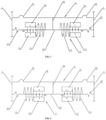
- the third embodiment is basically identical in structure to the first embodiment, except for the followings: the magnetic circuit unit 1 in the third embodiment includes two magnetic circuit coils 11 which are located at the opposed sides of two magnet groups respectively, that is, the two magnetic circuit coils 11 are located between the two magnet groups, and the ends of the two magnetic circuit coils 11 that are away from each other are fixedly connected with the corresponding magnet groups (as shown in FIG. 3 ).
- two magnetic circuit coils 11 may also be located at the contrary sides of the two magnet groups respectively, that is, the two magnetic circuit coils 11 are located at outer sides of the two magnet groups, and the ends of the two magnetic circuit coils 11 that are opposed to each other are fixedly connected with the corresponding magnet groups (as shown in FIG. 4 ).
- the two magnetic circuit coils 11 are synchronously powered on or off.
- the balanced iron core 21 When the two magnetic circuit coils 11 are in a powered-on state, the balanced iron core 21 generates opposite magnetic poles at positions corresponding to the two magnet groups, and action forces applied by the two magnet groups to the balanced iron core 21 are always consistent in direction, for example, synchronously up or down. In this case, the balanced iron core 21 drives the vibrating diaphragm 22 to vibrate up and down.
- the arrangement of two magnetic circuit coils 11 in the third embodiment belongs to a structural variation of the first embodiment and can achieve the same effect as the first embodiment.
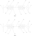
- the fourth embodiment has the same principle as the second embodiment.
- the fourth embodiment is basically identical in structure to the second embodiment, except for the followings: the magnetic circuit unit 1 in the fourth embodiment includes two magnetic circuit coils 11 which are located at the opposed sides of two magnet groups respectively, that is, the two magnetic circuit coils 11 are located between the two magnet groups, and the ends of the two magnetic circuit coils 11 that are away from each other are fixedly connected with the corresponding magnet groups (as shown in FIG. 5 ).
- two magnetic circuit coils 11 may also be located at the contrary sides of the two magnet groups respectively, that is, the two magnetic circuit coils 11 are located at outer sides of the two magnet groups, and the ends of the two magnetic circuit coils 11 that are opposed to each other are fixedly connected with the corresponding magnet groups (as shown in FIG. 6 ).
- the two magnetic circuit coils 11 are synchronously powered on or off.
- the balanced iron core 21 When the two magnetic circuit coils 11 are in a powered-on state, the balanced iron core 21 generates opposite magnetic poles at positions corresponding to the two magnet groups, and action forces applied by the two magnet groups to the balanced iron core 21 are always consistent in direction, for example, synchronously up or down. In this case, the balanced iron core 21 drives the vibrating diaphragm 22 to vibrate up and down.
- the arrangement of two magnetic circuit coils 11 in the fourth embodiment belongs to a structural variation of the second embodiment and can achieve the same effect as the second embodiment.
Landscapes
- Engineering & Computer Science (AREA)
- Physics & Mathematics (AREA)
- Acoustics & Sound (AREA)
- Signal Processing (AREA)
- Multimedia (AREA)
- Electromagnetism (AREA)
- Apparatuses For Generation Of Mechanical Vibrations (AREA)
- Electrostatic, Electromagnetic, Magneto- Strictive, And Variable-Resistance Transducers (AREA)
Applications Claiming Priority (2)
| Application Number | Priority Date | Filing Date | Title |
|---|---|---|---|
| CN201910396055.1A CN110012398B (zh) | 2019-05-14 | 2019-05-14 | 一种平衡振动系统 |
| PCT/CN2019/110531 WO2020228229A1 (zh) | 2019-05-14 | 2019-10-11 | 一种平衡振动系统 |
Publications (2)
| Publication Number | Publication Date |
|---|---|
| EP3972284A1 true EP3972284A1 (de) | 2022-03-23 |
| EP3972284A4 EP3972284A4 (de) | 2023-01-25 |
Family
ID=67176746
Family Applications (1)
| Application Number | Title | Priority Date | Filing Date |
|---|---|---|---|
| EP19928971.1A Pending EP3972284A4 (de) | 2019-05-14 | 2019-10-11 | System für ausgeglichene schwingung |
Country Status (5)
| Country | Link |
|---|---|
| US (1) | US11758331B2 (de) |
| EP (1) | EP3972284A4 (de) |
| JP (1) | JP7241452B2 (de) |
| CN (1) | CN110012398B (de) |
| WO (1) | WO2020228229A1 (de) |
Families Citing this family (8)
| Publication number | Priority date | Publication date | Assignee | Title |
|---|---|---|---|---|
| CN110012398B (zh) * | 2019-05-14 | 2024-03-12 | 潘国昌 | 一种平衡振动系统 |
| CN112203199B (zh) | 2019-07-08 | 2022-02-08 | 歌尔股份有限公司 | 换能器振动悬挂系统、换能器及电子设备 |
| CN112203198B (zh) * | 2019-07-08 | 2022-05-27 | 歌尔股份有限公司 | 换能器振动悬挂系统与驱动系统组件及其电子设备 |
| CN112203197B (zh) * | 2019-07-08 | 2021-11-09 | 歌尔股份有限公司 | 磁势换能器及其电子设备 |
| CN112243183B (zh) | 2019-07-19 | 2023-08-04 | 歌尔股份有限公司 | 磁势扬声器及其电子设备 |
| CN110460940B (zh) * | 2019-08-29 | 2020-10-16 | 潘国昌 | 一种平衡振动组件的装配方法 |
| CN112934682A (zh) * | 2021-03-05 | 2021-06-11 | 日昌升建筑新材料设计研究院有限公司 | 一种电磁摇摆式振动筛 |
| CN115616724B (zh) * | 2022-10-12 | 2025-11-04 | 西安知微传感技术有限公司 | 一种面内二维平动光学致动器 |
Family Cites Families (16)
| Publication number | Priority date | Publication date | Assignee | Title |
|---|---|---|---|---|
| JP2000343033A (ja) * | 1999-06-02 | 2000-12-12 | Star Engineering Co Ltd | 振動モータ |
| US7206425B2 (en) | 2003-01-23 | 2007-04-17 | Adaptive Technologies, Inc. | Actuator for an active noise control system |
| JP5112159B2 (ja) | 2008-04-25 | 2013-01-09 | フォスター電機株式会社 | 電磁型電気音響変換器 |
| CN102355617B (zh) * | 2011-08-15 | 2014-04-16 | 苏州恒听电子有限公司 | 用于扬声装置的动铁单元 |
| CN102361503A (zh) * | 2011-08-18 | 2012-02-22 | 苏州恒听电子有限公司 | 具有改良结构的耳机动铁单元 |
| JP5802547B2 (ja) | 2011-12-28 | 2015-10-28 | リオン株式会社 | 電気機械変換器と電気音響変換器及びそれを用いた補聴器 |
| JP5653543B1 (ja) | 2014-01-21 | 2015-01-14 | リオン株式会社 | 電気機械変換器及び電気音響変換器 |
| CN204465860U (zh) * | 2015-04-13 | 2015-07-08 | 常州阿木奇声学科技有限公司 | 体积小的磁力驱动组件及应用该磁力驱动组件的动铁单元 |
| CN104883650A (zh) * | 2015-06-05 | 2015-09-02 | 歌尔声学股份有限公司 | 振动发声装置 |
| CN204993851U (zh) * | 2015-10-28 | 2016-01-20 | 胡生正 | 一种可调校的动铁式发声装置及其耳机 |
| JP6625899B2 (ja) * | 2016-02-24 | 2019-12-25 | リオン株式会社 | 電気機械変換器 |
| JP6813423B2 (ja) * | 2017-04-25 | 2021-01-13 | リオン株式会社 | 電気機械変換器 |
| CN107426652A (zh) * | 2017-04-28 | 2017-12-01 | 北京欧意智能科技有限公司 | 平面振膜扬声器及耳机 |
| CN208522987U (zh) * | 2018-05-28 | 2019-02-19 | 苏州三色峰电子有限公司 | 一种基于动磁铁的双线圈微型受话器 |
| CN110012398B (zh) | 2019-05-14 | 2024-03-12 | 潘国昌 | 一种平衡振动系统 |
| CN209472763U (zh) * | 2019-05-14 | 2019-10-08 | 潘国昌 | 一种平衡振动系统 |
-
2019
- 2019-05-14 CN CN201910396055.1A patent/CN110012398B/zh active Active
- 2019-10-11 EP EP19928971.1A patent/EP3972284A4/de active Pending
- 2019-10-11 WO PCT/CN2019/110531 patent/WO2020228229A1/zh not_active Ceased
- 2019-10-11 JP JP2021564346A patent/JP7241452B2/ja active Active
- 2019-10-11 US US17/594,840 patent/US11758331B2/en active Active
Also Published As
| Publication number | Publication date |
|---|---|
| EP3972284A4 (de) | 2023-01-25 |
| CN110012398A (zh) | 2019-07-12 |
| JP2022524229A (ja) | 2022-04-28 |
| JP7241452B2 (ja) | 2023-03-17 |
| WO2020228229A1 (zh) | 2020-11-19 |
| US20220312121A1 (en) | 2022-09-29 |
| CN110012398B (zh) | 2024-03-12 |
| US11758331B2 (en) | 2023-09-12 |
Similar Documents
| Publication | Publication Date | Title |
|---|---|---|
| US11758331B2 (en) | Balanced vibration system | |
| US10931185B2 (en) | Linear vibration motor | |
| CN210120478U (zh) | 一种振动电机 | |
| CN109068244B (zh) | 电磁激励器以及屏幕发声装置 | |
| US11902764B2 (en) | Magnetic circuit structure of a transducer, a transducer and an electronic device comprising the same | |
| CN107171526B (zh) | 一种线性振动马达 | |
| US20190222106A1 (en) | Linear vibration motor | |
| AU2016200404A1 (en) | Multimedia acoustics system having audio frequency digital interface | |
| CN106941308B (zh) | 基于振动效应的能量采集装置 | |
| US20200213763A1 (en) | Sound Generator | |
| CN102570767A (zh) | 一种小行程节能音圈电机 | |
| WO2022006938A1 (zh) | 一种线性振动马达 | |
| WO2021000122A1 (zh) | 电磁激励器 | |
| CN204482029U (zh) | 一种扬声器马达组件及应用该马达组件的动铁单元 | |
| CN209982301U (zh) | 一种激励器及电子产品 | |
| CN204482030U (zh) | 一种扬声器用新型磁力驱动组件 | |
| US20220278599A1 (en) | Multi-solenoid linear vibration motor | |
| CN218997904U (zh) | 线性振动马达 | |
| CN209472763U (zh) | 一种平衡振动系统 | |
| US20110050006A1 (en) | Actuator | |
| CN107580287B (zh) | 一种受话器及其装配方法 | |
| CN117536994A (zh) | 一种被动磁轴承 | |
| CN103925987A (zh) | 惯性式动圈型电动传感器 | |
| CN117588490A (zh) | 一种被动磁轴承 | |
| CN205544871U (zh) | 一种直线电机及压缩机 |
Legal Events
| Date | Code | Title | Description |
|---|---|---|---|
| STAA | Information on the status of an ep patent application or granted ep patent |
Free format text: STATUS: THE INTERNATIONAL PUBLICATION HAS BEEN MADE |
|
| PUAI | Public reference made under article 153(3) epc to a published international application that has entered the european phase |
Free format text: ORIGINAL CODE: 0009012 |
|
| STAA | Information on the status of an ep patent application or granted ep patent |
Free format text: STATUS: REQUEST FOR EXAMINATION WAS MADE |
|
| 17P | Request for examination filed |
Effective date: 20211214 |
|
| AK | Designated contracting states |
Kind code of ref document: A1 Designated state(s): AL AT BE BG CH CY CZ DE DK EE ES FI FR GB GR HR HU IE IS IT LI LT LU LV MC MK MT NL NO PL PT RO RS SE SI SK SM TR |
|
| DAV | Request for validation of the european patent (deleted) | ||
| DAX | Request for extension of the european patent (deleted) | ||
| REG | Reference to a national code |
Ref country code: DE Ref legal event code: R079 Free format text: PREVIOUS MAIN CLASS: H04R0009060000 Ipc: H04R0011020000 |
|
| A4 | Supplementary search report drawn up and despatched |
Effective date: 20230102 |
|
| RIC1 | Information provided on ipc code assigned before grant |
Ipc: H04R 11/02 20060101AFI20221220BHEP |
|
| STAA | Information on the status of an ep patent application or granted ep patent |
Free format text: STATUS: EXAMINATION IS IN PROGRESS |
|
| 17Q | First examination report despatched |
Effective date: 20241018 |