EP3971564B1 - Spray ionization device, analysis device, and surface coating device - Google Patents
Spray ionization device, analysis device, and surface coating device Download PDFInfo
- Publication number
- EP3971564B1 EP3971564B1 EP20847268.8A EP20847268A EP3971564B1 EP 3971564 B1 EP3971564 B1 EP 3971564B1 EP 20847268 A EP20847268 A EP 20847268A EP 3971564 B1 EP3971564 B1 EP 3971564B1
- Authority
- EP
- European Patent Office
- Prior art keywords
- tube
- liquid
- outlet
- spray ionization
- channel
- Prior art date
- Legal status (The legal status is an assumption and is not a legal conclusion. Google has not performed a legal analysis and makes no representation as to the accuracy of the status listed.)
- Active
Links
Images





Classifications
-
- H—ELECTRICITY
- H01—ELECTRIC ELEMENTS
- H01J—ELECTRIC DISCHARGE TUBES OR DISCHARGE LAMPS
- H01J49/00—Particle spectrometers or separator tubes
- H01J49/02—Details
- H01J49/04—Arrangements for introducing or extracting samples to be analysed, e.g. vacuum locks; Arrangements for external adjustment of electron- or ion-optical components
- H01J49/0468—Arrangements for introducing or extracting samples to be analysed, e.g. vacuum locks; Arrangements for external adjustment of electron- or ion-optical components with means for heating or cooling the sample
-
- B—PERFORMING OPERATIONS; TRANSPORTING
- B05—SPRAYING OR ATOMISING IN GENERAL; APPLYING FLUENT MATERIALS TO SURFACES, IN GENERAL
- B05B—SPRAYING APPARATUS; ATOMISING APPARATUS; NOZZLES
- B05B5/00—Electrostatic spraying apparatus; Spraying apparatus with means for charging the spray electrically; Apparatus for spraying liquids or other fluent materials by other electric means
- B05B5/025—Discharge apparatus, e.g. electrostatic spray guns
- B05B5/053—Arrangements for supplying power, e.g. charging power
- B05B5/0533—Electrodes specially adapted therefor; Arrangements of electrodes
-
- B—PERFORMING OPERATIONS; TRANSPORTING
- B05—SPRAYING OR ATOMISING IN GENERAL; APPLYING FLUENT MATERIALS TO SURFACES, IN GENERAL
- B05B—SPRAYING APPARATUS; ATOMISING APPARATUS; NOZZLES
- B05B1/00—Nozzles, spray heads or other outlets, with or without auxiliary devices such as valves, heating means
- B05B1/14—Nozzles, spray heads or other outlets, with or without auxiliary devices such as valves, heating means with multiple outlet openings; with strainers in or outside the outlet opening
-
- B—PERFORMING OPERATIONS; TRANSPORTING
- B05—SPRAYING OR ATOMISING IN GENERAL; APPLYING FLUENT MATERIALS TO SURFACES, IN GENERAL
- B05B—SPRAYING APPARATUS; ATOMISING APPARATUS; NOZZLES
- B05B5/00—Electrostatic spraying apparatus; Spraying apparatus with means for charging the spray electrically; Apparatus for spraying liquids or other fluent materials by other electric means
- B05B5/025—Discharge apparatus, e.g. electrostatic spray guns
- B05B5/03—Discharge apparatus, e.g. electrostatic spray guns characterised by the use of gas, e.g. electrostatically assisted pneumatic spraying
-
- B—PERFORMING OPERATIONS; TRANSPORTING
- B05—SPRAYING OR ATOMISING IN GENERAL; APPLYING FLUENT MATERIALS TO SURFACES, IN GENERAL
- B05B—SPRAYING APPARATUS; ATOMISING APPARATUS; NOZZLES
- B05B5/00—Electrostatic spraying apparatus; Spraying apparatus with means for charging the spray electrically; Apparatus for spraying liquids or other fluent materials by other electric means
- B05B5/025—Discharge apparatus, e.g. electrostatic spray guns
- B05B5/043—Discharge apparatus, e.g. electrostatic spray guns using induction-charging
-
- B—PERFORMING OPERATIONS; TRANSPORTING
- B05—SPRAYING OR ATOMISING IN GENERAL; APPLYING FLUENT MATERIALS TO SURFACES, IN GENERAL
- B05B—SPRAYING APPARATUS; ATOMISING APPARATUS; NOZZLES
- B05B7/00—Spraying apparatus for discharge of liquids or other fluent materials from two or more sources, e.g. of liquid and air, of powder and gas
- B05B7/02—Spray pistols; Apparatus for discharge
- B05B7/04—Spray pistols; Apparatus for discharge with arrangements for mixing liquids or other fluent materials before discharge
- B05B7/0408—Spray pistols; Apparatus for discharge with arrangements for mixing liquids or other fluent materials before discharge with arrangements for mixing two or more liquids
-
- B—PERFORMING OPERATIONS; TRANSPORTING
- B05—SPRAYING OR ATOMISING IN GENERAL; APPLYING FLUENT MATERIALS TO SURFACES, IN GENERAL
- B05B—SPRAYING APPARATUS; ATOMISING APPARATUS; NOZZLES
- B05B7/00—Spraying apparatus for discharge of liquids or other fluent materials from two or more sources, e.g. of liquid and air, of powder and gas
- B05B7/02—Spray pistols; Apparatus for discharge
- B05B7/04—Spray pistols; Apparatus for discharge with arrangements for mixing liquids or other fluent materials before discharge
- B05B7/0416—Spray pistols; Apparatus for discharge with arrangements for mixing liquids or other fluent materials before discharge with arrangements for mixing one gas and one liquid
- B05B7/0441—Spray pistols; Apparatus for discharge with arrangements for mixing liquids or other fluent materials before discharge with arrangements for mixing one gas and one liquid with one inner conduit of liquid surrounded by an external conduit of gas upstream the mixing chamber
- B05B7/045—Spray pistols; Apparatus for discharge with arrangements for mixing liquids or other fluent materials before discharge with arrangements for mixing one gas and one liquid with one inner conduit of liquid surrounded by an external conduit of gas upstream the mixing chamber the gas and liquid flows being parallel just upstream the mixing chamber
-
- B—PERFORMING OPERATIONS; TRANSPORTING
- B05—SPRAYING OR ATOMISING IN GENERAL; APPLYING FLUENT MATERIALS TO SURFACES, IN GENERAL
- B05B—SPRAYING APPARATUS; ATOMISING APPARATUS; NOZZLES
- B05B7/00—Spraying apparatus for discharge of liquids or other fluent materials from two or more sources, e.g. of liquid and air, of powder and gas
- B05B7/02—Spray pistols; Apparatus for discharge
- B05B7/06—Spray pistols; Apparatus for discharge with at least one outlet orifice surrounding another approximately in the same plane
-
- B—PERFORMING OPERATIONS; TRANSPORTING
- B05—SPRAYING OR ATOMISING IN GENERAL; APPLYING FLUENT MATERIALS TO SURFACES, IN GENERAL
- B05B—SPRAYING APPARATUS; ATOMISING APPARATUS; NOZZLES
- B05B7/00—Spraying apparatus for discharge of liquids or other fluent materials from two or more sources, e.g. of liquid and air, of powder and gas
- B05B7/02—Spray pistols; Apparatus for discharge
- B05B7/06—Spray pistols; Apparatus for discharge with at least one outlet orifice surrounding another approximately in the same plane
- B05B7/061—Spray pistols; Apparatus for discharge with at least one outlet orifice surrounding another approximately in the same plane with several liquid outlets discharging one or several liquids
-
- B—PERFORMING OPERATIONS; TRANSPORTING
- B05—SPRAYING OR ATOMISING IN GENERAL; APPLYING FLUENT MATERIALS TO SURFACES, IN GENERAL
- B05B—SPRAYING APPARATUS; ATOMISING APPARATUS; NOZZLES
- B05B7/00—Spraying apparatus for discharge of liquids or other fluent materials from two or more sources, e.g. of liquid and air, of powder and gas
- B05B7/02—Spray pistols; Apparatus for discharge
- B05B7/08—Spray pistols; Apparatus for discharge with separate outlet orifices, e.g. to form parallel jets, i.e. the axis of the jets being parallel, to form intersecting jets, i.e. the axis of the jets converging but not necessarily intersecting at a point
- B05B7/0807—Spray pistols; Apparatus for discharge with separate outlet orifices, e.g. to form parallel jets, i.e. the axis of the jets being parallel, to form intersecting jets, i.e. the axis of the jets converging but not necessarily intersecting at a point to form intersecting jets
- B05B7/0815—Spray pistols; Apparatus for discharge with separate outlet orifices, e.g. to form parallel jets, i.e. the axis of the jets being parallel, to form intersecting jets, i.e. the axis of the jets converging but not necessarily intersecting at a point to form intersecting jets with at least one gas jet intersecting a jet constituted by a liquid or a mixture containing a liquid for controlling the shape of the latter
-
- B—PERFORMING OPERATIONS; TRANSPORTING
- B05—SPRAYING OR ATOMISING IN GENERAL; APPLYING FLUENT MATERIALS TO SURFACES, IN GENERAL
- B05B—SPRAYING APPARATUS; ATOMISING APPARATUS; NOZZLES
- B05B7/00—Spraying apparatus for discharge of liquids or other fluent materials from two or more sources, e.g. of liquid and air, of powder and gas
- B05B7/16—Spraying apparatus for discharge of liquids or other fluent materials from two or more sources, e.g. of liquid and air, of powder and gas incorporating means for heating or cooling the material to be sprayed
- B05B7/1606—Spraying apparatus for discharge of liquids or other fluent materials from two or more sources, e.g. of liquid and air, of powder and gas incorporating means for heating or cooling the material to be sprayed the spraying of the material involving the use of an atomising fluid, e.g. air
- B05B7/1613—Spraying apparatus for discharge of liquids or other fluent materials from two or more sources, e.g. of liquid and air, of powder and gas incorporating means for heating or cooling the material to be sprayed the spraying of the material involving the use of an atomising fluid, e.g. air comprising means for heating the atomising fluid before mixing with the material to be sprayed
- B05B7/162—Spraying apparatus for discharge of liquids or other fluent materials from two or more sources, e.g. of liquid and air, of powder and gas incorporating means for heating or cooling the material to be sprayed the spraying of the material involving the use of an atomising fluid, e.g. air comprising means for heating the atomising fluid before mixing with the material to be sprayed and heat being transferred from the atomising fluid to the material to be sprayed
- B05B7/1626—Spraying apparatus for discharge of liquids or other fluent materials from two or more sources, e.g. of liquid and air, of powder and gas incorporating means for heating or cooling the material to be sprayed the spraying of the material involving the use of an atomising fluid, e.g. air comprising means for heating the atomising fluid before mixing with the material to be sprayed and heat being transferred from the atomising fluid to the material to be sprayed at the moment of mixing
-
- B—PERFORMING OPERATIONS; TRANSPORTING
- B05—SPRAYING OR ATOMISING IN GENERAL; APPLYING FLUENT MATERIALS TO SURFACES, IN GENERAL
- B05B—SPRAYING APPARATUS; ATOMISING APPARATUS; NOZZLES
- B05B7/00—Spraying apparatus for discharge of liquids or other fluent materials from two or more sources, e.g. of liquid and air, of powder and gas
- B05B7/16—Spraying apparatus for discharge of liquids or other fluent materials from two or more sources, e.g. of liquid and air, of powder and gas incorporating means for heating or cooling the material to be sprayed
- B05B7/22—Spraying apparatus for discharge of liquids or other fluent materials from two or more sources, e.g. of liquid and air, of powder and gas incorporating means for heating or cooling the material to be sprayed electrically, magnetically or electromagnetically, e.g. by arc
-
- H—ELECTRICITY
- H01—ELECTRIC ELEMENTS
- H01J—ELECTRIC DISCHARGE TUBES OR DISCHARGE LAMPS
- H01J49/00—Particle spectrometers or separator tubes
- H01J49/02—Details
- H01J49/10—Ion sources; Ion guns
- H01J49/16—Ion sources; Ion guns using surface ionisation, e.g. field-, thermionic- or photo-emission
- H01J49/165—Electrospray ionisation
Definitions
- the present invention relates to a spray ionization device, an analysis device, and a surface coating device.
- a mass spectrometer can count ions constituting a substance by each mass-to-charge ratio to obtain ion intensity which is quantitative information on the substance.
- the mass spectrometer can perform a more accurate analysis by obtaining an ion intensity having a good signal-to-noise ratio. Therefore, an analysis target, which is an ionized or a charged material, needs to be sufficiently introduced.
- Examples of a method of ionizing a liquid sample include an electrospray ionization method.
- electrospray ionization method high voltage of several kilovolts is applied to a sample solution in a narrow tube, a liquid cone (so-called Taylor cone) is formed at the tip of an outlet. Electrically charged droplets are ejected from the tip of the liquid cone, solvents evaporate to reduce the volume of the electrically charged droplets, and the electrically charged droplets finally split apart to generate gas-phase ions.
- This method can form electrically charged droplets at a rate of ejecting 1 to 10 ⁇ L/min of solution, in which the eject rate is not sufficient for use in conjunction with a liquid chromatography method.
- a gas spray assisted electrospray ionization method may be an example of a method for supporting generation of electrically charged droplets and vaporization of solvents by ejecting a gas from an outer tube surrounding a narrow tube of a sample solution, in order to promote vaporization of electrically charged droplets.
- Patent Documents 2 and 3 also describe spray ionization devices.
- US2015/206729A1 discloses two different tubes bearing liquids surrounded by an outer tube that includes an ejection port covered with a porous member. The device generates neutral droplets.
- US2017/025262A1 discloses an electrospray device having electrodes located in the sample liquid.
- WO2020241098 belongs to the prior art under Article 54(3) EPC and discloses a spray ionization device, comprising an outer tube, the outer tube including an ejection port covered with a porous member at one end; a tube within the outer tube through which a liquid can flow with an outlet for ejecting the liquid at the one end; wherein the porous member is at a distance downstream of the outlet; an electrode being arranged to apply voltage to the liquid, wherein the device is configured so that charged droplets generated from the liquid are ejected from the ejection port.
- An object of the present invention is to solve the aforementioned problem and provide a spray ionization device capable of stably forming charged droplets in which a plurality of sample liquids are mixed, and an analysis device and a surface coating device including the same.
- One aspect of the present invention provides a spray ionization device as defined in appended claim 1.
- voltage is applied to at least one of the first liquid and the second liquid, and the first liquid and the second liquid ejected from the first outlet and the second outlet, respectively, and the gas from the gas channel collide with the non-opening of the porous member to form a turbulent flow state.
- electrically charged droplets in which the first liquid and the second liquid are mixed, are formed, and the charged droplets are introduced from the opening of the porous member and ejected from the ejection port.
- the first liquid and the second liquid at least one of which is charged, are mixed immediately after being ejected and form electrically charged droplets, whereby the spray ionization device capable of stably ejecting charged droplets can be provided.
- the liquids can be introduced into the analysis device immediately after the chemical reaction takes place by mixing by ejection, whereby the spray ionization device capable of forming droplets allowing for accurately analyzing the reactant can be provided.
- the second liquid is electrically charged by applying voltage to the second liquid, whereby the spray ionization device capable of forming mixed droplets of the first liquid and the second liquid, which are electrically charged, can be provided.
- One other aspect of the present invention provides an analysis device, including: the spray ionization device of the aspect described above; and an analysis unit that introduces and analyzes the electrically charged droplets sprayed from the spray ionization device.
- the spray ionization device achieves various operational effects of the aspect, whereby the analysis device capable of performing analysis characterized by the operational effects can be provided.
- FIG. 1 is a diagram schematically illustrating a configuration of a spray ionization device according to a first embodiment of the present invention.
- Fig. 2A is an enlarged cross-sectional view of a nozzle of a sprayer along the longitudinal direction of the sprayer.
- FIG. 2B is a view along arrows Y-Y in FIG. 2A .
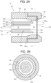
- FIGS. 3A and 3B are cross-sectional views schematically illustrating a configuration of an electrode.
- a spray ionization device 10 includes: a sprayer 11; containers 12 and 13 containing sample liquids Lf 1 and Lf 2 , respectively, to be supplied to the sprayer 11; a cylinder 14 for containing a spraying gas Gf to be supplied to the sprayer 11; and a high-voltage power source 16 for applying high voltage to the sample liquid Lf 1 via an electrode 15.
- a nozzle 18 for ejecting electrically charged droplets is formed at one end (hereinafter also referred to as an ejection end) of the sprayer 11 of the spray ionization device 10.
- the sample liquids Lf 1 and Lf 2 and the spraying gas Gf are supplied from further toward the opposite end than the nozzle 18 (hereinafter also referred to as a supply end) of the sprayer 11.
- the sample liquids Lf 1 and Lf 2 are supplied from supply ports 22 s and 23 s from the containers 12 and 13, respectively, by way of a pump 19 and the like.
- the sample liquids Lf 1 and Lf 2 may be continuously or intermittently supplied.
- the sample liquids Lf 1 and Lf 2 may contain an analysis target in solvents, or may contain dissolved components, particulate matter, or the like, for example.
- the spraying gas Gf is supplied from the cylinder 14 through the valve 20 to the supply port 24 s .
- Inert gas such as nitrogen gas or argon gas, or air can be used for the spraying gas Gf, for example.
- a heating unit 21 such as a heater or dryer for heating the spraying gas Gf may be provided between the cylinder 14 or the valve 20 and the supply port 24 s .
- the spraying gas Gf is heated, whereby vaporization of solvents in the ejected sample liquids Lf 1 and Lf 2 can be promoted, and electrically charged droplets can be obtained more efficiently.
- the sprayer 11 includes: a first liquid supply tube 22, a second liquid supply tube 23 surrounding the first liquid supply tube 22 with a gap; and a gas supply tube 24 surrounding the second liquid supply tube 23 with a gap.
- Sprayer 11 has a triple tube structure including the first liquid supply tube 22 on the inner side, the second liquid supply tube 23 on the outer side, and the gas supply tube 24.
- the first liquid supply tube 22, the second liquid supply tube 23, and gas supply tube 24 are preferably coaxial with each other.
- a tubular first channel 25 is defined on an inner circumferential surface 22b of the first liquid supply tube 22.
- the first liquid supply tube 22 has an outlet 22a, in the nozzle 18.
- the sample liquid Lf 1 is supplied from the supply port 22 s of the first liquid supply tube 22, flows through the first channel 25, and is ejected from the outlet 22a.
- the first liquid supply tube 22 may be, for example, a straight tube.
- a diameter (inner diameter) of the inner circumferential surface 22b is preferably 10 um to 250 um, and a diameter (outer diameter) of the outer circumferential surface 22c is preferably 100 um to 500 ⁇ m.
- the inner circumferential surface 23b of the second liquid supply tube 23 and the outer circumferential surface 22c of the first liquid supply tube 22 define a second channel 26.
- the second liquid supply tube 23 has an outlet 23a, in the nozzle 18.
- the sample liquid Lf 2 is supplied from the supply port 23 s of the second liquid supply tube 23, flows through the second channel 26, and is ejected from the outlet 23a.
- the second liquid supply tube 23 may be, for example, a straight tube.
- a diameter (inner diameter) of the inner circumferential surface 23b is preferably 200 um to 700 um, and a diameter (outer diameter) of the outer circumferential surface 23c is preferably 300 um to 800 ⁇ m.
- the first liquid supply tube 22 and the second liquid supply tube 23 may be formed of a dielectric material made of glass and plastics.
- An electrode 15 as described later is provided to at least one of the first liquid supply tube 22 and the second liquid supply tube 23.
- part of at least one of the first liquid supply tube 22 and the second liquid supply tube 23 may be made of an electrical conductor material to form the electrode 15.
- Entirety of at least one of the first liquid supply tube 22 and the second liquid supply tube 23 may be made of an electrical conductor material, e.g., a metal tube such as stainless steel, to form the electrode 15.
- the inner circumferential surface 24b of the gas supply tube 24 and the outer circumferential surface 23c of the second liquid supply tube 23 define the gas channel 28.
- the gas supply tube 24 includes an opening 24b 2 , in the nozzle 18.
- a diameter (inner diameter) of the inner circumferential surface 24b of the gas supply tube 24 is not limited in particular, and is, for example, 4 mm, further toward the supply end than the nozzle 18.
- the gas supply tube 24 is preferably made of a dielectric material such as glass or plastics, and further preferably made of polyether ether ketone resin (PEEK resin).
- PEEK resin polyether ether ketone resin
- the pressurized spraying gas Gf is supplied from the supply port 24 s of the gas supply tube 24, flows through the gas channel 28, and is ejected from a gap between the outlet 23a of the second liquid supply tube 23 and the gas supply tube 24.
- a flow rate of the spraying gas Gf is appropriately set in accordance with the flow rate of the sample liquids Lf 1 and Lf 2 , and is set to 0.5 L/min to 5.0 L/min, for example.
- High-voltage power source 16 is a high-voltage DC or high-frequency alternating-current voltage capable power supply.
- the high-voltage power source 16 is connected to the electrode 15 arranged so as to be able to contact the sample liquid Lf 1 flowing through the sprayer 11.
- the high-voltage power source 16 applies voltage of e.g., 4.0 kV to the electrode 15, and preferably applies voltage in a range of 0.5 kV to 10.0 kV in terms of ionization.
- the waveform of the alternating-current voltage is not limited in particular, and is a sine wave, a rectangular wave, or the like.
- the frequency of the alternating-current voltage is preferably 100 Hz to 1000 kHz.
- the electrode 15 is provided further toward the supply end than the outlet 22a of the first liquid supply tube 22. As illustrated in FIG. 3A , the electrode 15 is formed so as to be able to contact the sample liquid Lf 1 flowing through the first channel 25.
- a tip 15a of the electrode 15 may be provided so as to form a surface contiguous with the inner circumferential surface 22b of the first liquid supply tube 22, or may be provided so as to project into the first channel 25. As long as the tip 15a of the electrode 15 can contact the sample liquid Lf 1 , the tip 15a may be provided so as to recede from the inner circumferential surface 22b of the first liquid supply tube 22.
- the electrode 115 may include an annular member 115a in the first channel 25.
- the sample liquid Lf 1 can flow through the inside the annular member 115a.
- high voltage can be more easily applied to the sample liquid Lf 1 .
- the electrode 15 or 115 is preferably made of a platinumgroup element, gold, or alloy thereof, in terms of excellent corrosion resistance.
- the electrode 15 or 115 may be made of a metal material such as titanium, tungsten, or stainless steel which may be used for a common electrode.
- part or entirety of the first liquid supply tube 22 may be made of an electrical conductor material to form the electrode 15.
- the outlet 22a of the liquid supply tube 22 may be made of an electrical conductor material to form the electrode 15.
- the electrode 15 may be formed in substantially the same manner as the configuration illustrated in FIGS. 3A and 3B , and may be provided further toward the ejection end than the supply port 23 s of the sample liquid Lf 2 .
- An ejection port 30 is provided to the gas supply tube 24, in the nozzle 18.
- FIG. 4 illustrates a view of the nozzle observed from downstream of the ejection port.
- a porous member 31 is provided to the ejection port 30.
- the porous member 31 is sandwiched between the tip portion 24d of the gas supply tube 24 and a retaining member 32.
- the porous member 31 is arranged so as to cover the opening 24b 2 of the gas supply tube 24.
- the porous member 31 is a material having a multitude of openings, such as a porous film or a reticulated member, and can be, e.g., a film, a mesh sheet or the like, in which a multitude of openings are formed by microfabrication.
- a dielectric material can be used for the mesh sheet, and PEEK resin can be used therefor, for example.
- the mesh sheet has horizontal lines and vertical lines with an interval of 70 ⁇ m, for example, in which a vertical and horizontal size of each aperture is 35 um, for example.
- the porous member 31 is arranged at a gap downstream of the outlet 22a of the first liquid supply tube 22 and the outlet 23a of the second liquid supply tube 23.
- this gap also referred to as the "mixing region 33"
- the electrically charged sample liquid Lf 1 ejected from outlet 22a of the first liquid supply tube 22, the sample liquid Lf 2 ejected from the outlet 23a of the second liquid supply tube 23, and the spraying gas Gf collide with a non-opening of the porous member 31 to form a turbulent flow state.
- the sample liquid Lf 1 and the sample liquid Lf 2 are atomized into droplets, and the electrically charged droplets of the sample liquid Lf 1 and the droplets of the sample liquid Lf 2 are combined to form electrically charged mixed droplets in a mixed state. Chemical reactions take place in the electrically charged mixed droplets, depending on the components of sample liquids Lf 1 and Lf 2 .
- a distance between the porous member 31 and the outlet 23a of the second liquid supply tube 23 is preferably 5 um or more and 1000 um or less, from a perspective that the electrically charged droplets of the sample liquid Lf 1 and the droplets of the sample liquid Lf 2 are mixed in the mixing region 33, electrically charged mixed droplets are sufficiently formed, and the droplets are atomized.
- the outlet 23a of the second liquid supply tube 23 is preferably arranged at the same position as, or protrudes further downstream than, the outlet 22a of the first liquid supply tube 22 in the ejection direction, from a perspective that droplets of the sample liquid Lf 1 and droplets of the sample liquid Lf 2 can be easily mixed in the mixing region 33.
- a distance between the outlet 23a and the outlet 22a in the ejection direction is particularly preferably set between 0 um and 1000 um.
- the electrically charged and atomized mixed droplets flow through the opening of the porous member 31 by way of the spraying gas Gf, and are ejected from the ejection port 30.
- the retaining member 32 may be formed at an angle so as to have a diameter that progressively increases downstream from the ejection port 30.
- the channel area of the gas channel 28 preferably progressively decreases such that the diameter of the gas supply tube 24 progressively decreases in a portion 24b 1 of the inner circumferential surface from upstream toward downstream.
- a constriction portion 34 is preferably provided to the gas supply tube 24. The constriction portion 34 is arranged further upstream than the outlet 23a of the second liquid supply tube 23.
- the channel area is an area occupied by the gas channel 28 in a plane perpendicular to the longitudinal direction of sprayer 11, and is an area surrounded by the inner circumferential surface 24b of the gas supply tube 24 and the outer circumferential surface 23c of the second liquid supply tube 23 as illustrated in FIG. 2B .
- the constriction portion 34 is preferably provided 50 um to 5000 um upstream of the outlet 23a.
- a distance between the portion 24b 1 of the inner circumferential surface of gas supply tube 24 and the outer circumferential surface 23c of the second liquid supply tube 23 is preferably set to 20 um to 400 um, in the constriction portion 34.
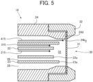
- FIG. 5 is a cross-sectional view illustrating a schematic configuration of another variation of the electrode.
- the electrode may be arranged so as to reach the nozzle 18 of the sprayer 11.
- the electrode 215 may be arranged through the inside of the first channel 25 of the first liquid supply tube 22 to reach the outlet 22a of the liquid supply tube 22.
- the electrode 315 may be arranged through the inside of the second channel 26 of the second liquid supply tube 23 to reach the outlet 23a of the second liquid supply tube 23.
- the electrodes 215 and 315 can be arranged proximate to the outlets 22a and 23a, respectively, to an extent that ejection of the sample liquids Lf 1 and Lf 2 from the outlets 22a and 23a is not hindered. As a result, voltages can be applied to the sample liquid Lf 1 or Lf 2 for the duration of flowing through the respective channels, so that the sample liquid can be sufficiently electrically charged.
- the electrode 415 may be arranged through the gas channel 28 of the gas supply tube 24 to reach the mixing zone 33 upstream of the porous member 31. As a result, droplets or mixed droplets of the sample liquid Lf 1 and Lf 2 generated in the mixing region 33 can be electrically charged.
- FIGS. 6A and 6B are cross-sectional views of the nozzle of the first variation of the sprayer according to the first embodiment of the present invention, in which FIG. 6A is an enlarged cross-sectional view along the longitudinal direction of sprayer, and FIG. 6B is a view along arrows Y-Y in FIG. 6A .
- the sprayer 111 includes: a first liquid supply tube 122; a second liquid supply tube 123 extending in parallel with the first liquid supply tube 122; a gas supply tube 24 surrounding the first liquid supply tube 122 and the second liquid supply tube 123; and the electrode 15 for applying high voltage to the sample liquid Lf 1 flowing through the first liquid supply tube 122.
- the electrode 15 has the same configuration as illustrated in FIGS. 1 , 3A , 3B and 5 .
- the first liquid supply tube 122 has a configuration similar to that of the first liquid supply tube 122 illustrated in FIGS. 1 , 2A and 2B .
- a tubular first channel 125 is defined on an inner circumferential surface 122b of the first liquid supply tube 122.
- the first liquid supply tube 122 includes an outlet 122a, in the nozzle 118.
- the second liquid supply tube 123 has a configuration similar to that of the first liquid supply tube 122, includes a tubular second channel 126, and includes an outlet 123a, in the nozzle 118.
- the gas supply tube 24 has a configuration similar to that of the gas supply tube 24 illustrated in FIGS. 1 , 2A and 2B .
- the gas channel 128 of the gas supply tube 24 is defined by the outer circumferential surfaces 122c and 123c of the first liquid supply tube 122 and the second liquid supply tube 123, and the inner circumferential surface 24b of the gas supply tube 24.
- the spraying gas Gf flows through the gas channel 128.
- the channel area of the gas channel 128 preferably progressively decreases such that the diameter of the gas supply tube 24 progressively decreases in the portion 24b 1 of the inner circumferential surface from upstream toward downstream.
- a constriction portion 134 is preferably provided to the gas supply tube 24.
- the constriction portion 134 is formed between the portion 24b 1 of the inner circumferential surface of the gas supply tube 24 and a portion of the outer circumferential surfaces 122c and 123c of the first liquid supply tube 122 and the second liquid supply tube 123, and achieves the same operation and effects as the constriction portion 34 illustrated in FIGS. 2A and 2B .
- the outlet 122a of the first liquid supply tube 122 and the outlet 123a of the second liquid supply tube 123 are arranged at substantially the same position in the ejection direction.
- a mixing region 133 for the sample liquids Lf 1 and Lf 2 and the spraying gas Gf is formed between the outlets 122a and 123a and the porous member 31, in which atomized and electrically charged mixed droplets are generated in the same manner as in the mixing region 33 illustrated in FIG. 2A .
- the electrically charged and atomized mixed droplets pass through the opening of the porous member 31 by way of the spraying gas Gf, and are ejected from the ejection port 130.
- a liquid supply tube for supplying and mixing still another sample liquid may be added to the first liquid supply tube 122 and the second liquid supply tube 123.
- a third liquid supply tube may be provided in parallel with the second liquid supply tube 23 illustrated in FIGS. 2A and 2B .
- FIG. 7 is a cross-sectional view of the nozzle of the second variation of the sprayer according to the first embodiment, and is a cross-sectional view corresponding to FIG. 6B .
- the sprayer 211 is provided with a third liquid supply tube 230 in parallel with the first liquid supply tube 122 and the second liquid supply tube 123.
- the sample liquid is ejected from each of the outlets 122a, 123a and 230a of the nozzle 218.
- the spraying gas Gf is ejected from the gas channel 228 to form a mixing region (not illustrated).
- Four or more liquid supply tubes may be provided.
- FIG. 8 is a diagram schematically illustrating a configuration of a spray ionization device according to a second embodiment of the present invention.
- a sprayer 311 in the case of a spray ionization device 310, includes a second gas supply tube 330 surrounding the gas supply tube 24, and a nozzle 318 has the same configuration as the nozzle 18 illustrated in FIGS. 2A and 2B .
- Sheath gas Gf 2 is supplied from a cylinder 314 via a valve 320 to a supply port 330s of a second gas supply tube 330.
- the second gas supply tube 330 includes a gas channel 331.
- the gas channel 331 is defined by the outer circumferential surface 24c of the gas supply tube 24 and an inner circumferential surface 330b of the second gas supply tube 330, and extends in the ejection direction.
- the inner circumferential surface 330b of the second gas supply tube 330 has a constant diameter toward the outlet 330a.
- the flow of the sheath gas Gf 2 flowing through the gas channel 331 is restricted from spreading by the inner circumferential surface 330b of the second gas supply tube 330 toward the outlet 330a.
- the electrically charged mixed droplets ejected from the nozzle 318 are enveloped in the sheath gas Gf 2 .
- the electrically charged mixed droplets are ejected from the outlet 330a of the second gas supply tube 330 along the ejection direction.
- the sprayer 311 can eject focused and electrically charged mixed droplets.
- a heating unit 319 may be provided downstream of the valve 320 so as to supply the sheath gas Gf 2 as heated gas.
- a heating unit such as a ring-heater (not illustrated) may be provided downstream of the retaining member 32 of the gas supply tube 24 so as to surround the second gas supply tube 330. As a result, desolvation of droplets can be supported.
- the sprayer 311 can employ the sprayer 111 having the configuration illustrated in FIGS. 6A and 6B and the sprayer 211 having the configuration illustrated in FIG. 7 , in which the same effects can be achieved.
- FIG. 9 is a diagram schematically illustrating a configuration of a spray ionization device according to a third embodiment of the present invention.
- a sprayer 411 of a spray ionization device 410 includes a second gas supply tube 430.
- the second gas supply tube 430 has the same configuration as the second gas supply tube 330, except that the tip shape of the second gas supply tube 430 differs from the tip shape of the second 330 illustrated in FIG. 8 .
- the second gas supply tube 430 is formed so as to have a diameter that progressively decreases in a portion 430b 1 of the inner circumferential surface toward the outlet 430a. Accordingly, the channel area of the gas channel 431 progressively decreases.
- the sheath gas Gf 2 flowing through the gas channel 431 flows toward the outlet 430a such that the flow focuses while being restricted by the inner circumferential surface 430b of the second gas supply tube 430.
- the electrically charged mixed droplets ejected from the nozzle 318 are enveloped in the sheath gas Gf 2 and focus onto the axial center along the ejection direction.
- the focused and electrically charged mixed droplets are ejected from the outlet 430a of the second gas supply tube 430.
- FIG. 10 is a diagram schematically illustrating a configuration of an analysis device according to an embodiment of the present invention.
- an analysis device 500 includes a spray ionization device 10 and an analysis unit 501 for introducing atomized and electrically charged mixed droplets from the spray ionization device 10 and performing mass spectrometry or the like.
- the spray ionization device 10 can be applied to the first and second variations of the first embodiment and the spray ionization device of the second and third embodiments.
- the spray ionization device 10 sends the electrically charged mixed droplets, which have been atomized by ejecting a plurality of sample liquids, to the analysis unit 501.
- the atomized and electrically charged mixed droplets are introduced into the analysis unit 501 in a state in which the molecules, clusters, and the like of components contained in the droplets are electrically charged by evaporation of solvents.
- the analysis unit 501 includes, for example, an ion lens, a quadrupole mass filter, and a detection unit (all not illustrated).
- the detection unit detects the specific ions for each mass number, and outputs detection signals.
- the spray ionization device 10 efficiently generates ions of components of the droplets, in which sample liquids Lf 1 and Lf 2 are mixed, and can therefore be used as an ion source of trace components.
- the analysis device 500 is, for example, a liquid chromatography-mass spectrometry (LC/MS) device including the spray ionization device 10 as an ion source.
- LC/MS liquid chromatography-mass spectrometry
- Example 1 is the spray ionization device of the first embodiment illustrated in FIGS. 1 , 2A and 2B , in which the electrode 15 is arranged at the supply port 23 s of the second liquid supply tube 23 and contacts the sample liquid Lf 2 .
- the first liquid supply tube 22 is made of fused silica glass
- the second liquid supply tube 23 is made of PEEK resin
- the first liquid supply tube 22 has an inner diameter of 50 um and an outer diameter of 150 um
- the second liquid supply tube 23 has an inner diameter of 250 um and an outer diameter of 350 um
- the gas supply tube 24 has an inner diameter of 4000 ⁇ m
- each aperture of the porous member 31 (made of PEEK resin) has a vertical and horizontal size of 35 ⁇ m.
- Example 2 is the spray ionization device of the first embodiment illustrated in FIGS. 1 , 2A and FIG. 2B , in which the electrode 15 is made of stainless steel (SUS316) and provided to the first liquid supply tube 22, and high voltage is applied to the sample liquid Lf 1 flowing through the first liquid supply tube 22 and the sample liquid Lf 2 flowing through the second liquid supply tube 23, over the entire longitudinal direction of the first liquid supply tube 22.
- the first liquid supply tube 22 has an inner diameter of 50 um and an outer diameter of 320 um
- the second liquid supply tube 23 has an inner diameter of 530 um and an outer diameter of 700 um
- the gas supply tube 24 and the porous member 31 are the same as in the first embodiment.
- a sprayer (ESI-probe (ion source)) attached to model API2000, a mass spectrometer manufactured by AB SCIEX, U.S.A. was used in the Comparative Example 1.
- the ESI-probe of Comparative Example 1 has a structure in which only a single sample liquid is supplied to a sprayer.
- the sample liquids Lf 1 and Lf 2 were mixed by a T-connector upstream of the sprayer, and a solution of the sample liquids was supplied into the single sprayer, electrically charged, and sprayed.
- a mixed liquid (hereinafter, also referred to as "dAMP mixed liquid") composed of an aqueous deoxyadenosine monophosphate (dAMP) solution (50 ppm concentration) separated by liquid chromatograph and ammonium formate (pH 3) having concentration of 10 mM as a solvent was supplied as a sample solution Lf 2 to the second liquid supply tube 23 of Examples 1 and 2.
- the flow rate was 25 ⁇ L/min.
- aqueous ammoniacal solution for pH-adjustment (abbreviated as "NH 3 ") (pH 11) was supplied as a sample solution Lf 1 to the first liquid supply tube 22 of Examples 1 and 2.
- the flow rate was 25 ⁇ L/min.
- dAMP was separated in a low-pH solution and dissociated in the neutral region by a mass spectrometer to expect increase in dAMP sensitivity.
- the sample solution Lf 1 and Lf 2 were mixed by the T-connector at the base of the sprayer.
- the flow rate of the sample solution Lf 1 and Lf 2 was 25 ⁇ L/min.
- Nitrogen gas at 25°C was used for the spraying gas Gf in Examples 1 and 2 and Comparative Example 1.
- the gas flow rate was 2 L/min in Examples 1 and 2, and at a set value of 18 as a recommended value of the manufacturer of the mass spectrometer in Comparative Example 1.
- Example 1 a high-voltage power source (manufactured by AB SCIEX, Model API2000 equipment) was connected to the electrode, in which DC voltage of 4.5 kV was applied to the sample solution Lf 2 in Example 1, and applied to the sample solution Lf 1 and Lf 2 by the first liquid supply tube 22 made of stainless steel in Example 2.
- DC voltage of 4.5 kV was applied to a sample solution in which the sample solution Lf 1 and Lf 2 were mixed.
- FIG. 11A is a diagram illustrating an example of the mass chromatogram of Example 1
- FIG. 11B is a diagram illustrating an example of the mass chromatogram of Comparative Example 1.
- the horizontal axis represents the retention time (minutes) of the mass chromatogram
- the vertical axis represents the signal intensity (counts).
- FIG. 12 is a diagram illustrating another Measurement Example of signal intensity of Examples 1 and 2 and Comparative Example 1.
- the signal intensity of FIG. 13 was also determined in the same manner.
- Example 1 when Example 1 is compared with Comparative Example 1, the average value of the signal intensity is substantially equivalent; however, the relative standard deviation is extremely small as about 1/11 in Example 1. It was found that the variation in signal intensity was more suppressed and the signal intensity was more stable in Example 1 than in Comparative Example 1. As a result, it was found that the spray ionization device of the first embodiment can stably obtain electrically charged droplets, in which the dAMP mixed solution and NH 3 are uniformly mixed.
- the average value of the signal intensity in Example 2 is 4.6 times that in Comparative Example 1, and 4.3 times that in Example 1, revealing that Example 2 can perform ionization extremely efficiently. It can be inferred that this is achieved by the spray ionization device of the second embodiment which applies high voltage to the dAMP mixed solution and NH 3 over the entire length of the first liquid supply tube 22.
- Example 3 mimics an aspect, in which the sprayer of Example 1 is applied to the sprayer having the second gas supply tube 330 illustrated in FIG. 8 , and in which the sheath gas Gf 2 heated to 80°C by a heater was supplied downstream surrounding the flow of the mixed droplets ejected from the ejection port 30.
- the sheath gas Gf 2 at 80°C was supplied to the sprayer of Example 2 in a similar manner.
- Examples 3 and 4 are the same as Examples 1 and 2, except for the above conditions.
- the spraying gas was supplied by setting the temperature to 300°C, using the heated gas nozzle of the sprayer attached to the mass spectrometer. Other conditions were the same as those in Measurement Example 1.
- FIG. 13 is a diagram illustrating Measurement Example of the signal intensity in Examples 3 and 4 and Comparative Example 2.
- the average value of the signal intensity in Example 3 was six times the average value of the signal intensity in Comparative Example 2, revealing that ionization can be performed extremely efficiently in Example 3.
- the relative standard deviation of the signal intensity was 60, and it was found that electrically charged droplets can be stably obtained, in which the dAMP mixed solution and NH 3 are uniformly mixed.
- Example 4 The average value of the signal intensity in Example 4 was 2.3 times the average value of the signal intensity in Example 3, revealing that ionization can be performed extremely efficiently in Example 4 as in the case of Example 2.
- the shape of the cross-section and the channel of the liquid supply tube has been described as circular, but may be triangular, square, pentagonal, hexagonal or other polygonal shapes, or other shapes such as an elliptical shape.
- the shape of the outer circumferential surface and the inner circumferential surface of the gas supply tube and the second gas supply tube can be selected from these shapes, depending on the shape of the liquid supply tube.
- the spray ionization device of the present invention can be used as an ion source of various devices; for example, in the field of trace sample analysis, the spray ionization device can be used for mass spectrometry such as mass spectrometry of molecules in a biological sample, elemental analysis, chemical morphology analysis, and charged particle analysis.
- the spray ionization device of the present invention can be used for surface coating devices utilizing surface coating techniques of spraying electrically charged droplets, and particle forming devices utilizing particle forming techniques by spraying electrically charged droplets of suspension.
- the spray ionization device of the present invention can be used for space processing devices utilizing sterilization, deodorization, dust collection, and chemical reactions, utilizing gas-phase or spatial chemical reactions by spraying electrically charged droplets.
Landscapes
- Physics & Mathematics (AREA)
- Chemical & Material Sciences (AREA)
- Analytical Chemistry (AREA)
- Electromagnetism (AREA)
- Engineering & Computer Science (AREA)
- Plasma & Fusion (AREA)
- Other Investigation Or Analysis Of Materials By Electrical Means (AREA)
- Nozzles (AREA)
- Electrostatic Spraying Apparatus (AREA)
Applications Claiming Priority (2)
| Application Number | Priority Date | Filing Date | Title |
|---|---|---|---|
| JP2019141193 | 2019-07-31 | ||
| PCT/JP2020/027873 WO2021020179A1 (ja) | 2019-07-31 | 2020-07-17 | スプレーイオン化装置、分析装置および表面塗布装置 |
Publications (3)
| Publication Number | Publication Date |
|---|---|
| EP3971564A1 EP3971564A1 (en) | 2022-03-23 |
| EP3971564A4 EP3971564A4 (en) | 2022-07-27 |
| EP3971564B1 true EP3971564B1 (en) | 2024-04-24 |
Family
ID=74229034
Family Applications (1)
| Application Number | Title | Priority Date | Filing Date |
|---|---|---|---|
| EP20847268.8A Active EP3971564B1 (en) | 2019-07-31 | 2020-07-17 | Spray ionization device, analysis device, and surface coating device |
Country Status (4)
| Country | Link |
|---|---|
| US (1) | US20220250102A1 (https=) |
| EP (1) | EP3971564B1 (https=) |
| JP (1) | JP7186471B2 (https=) |
| WO (1) | WO2021020179A1 (https=) |
Cited By (1)
| Publication number | Priority date | Publication date | Assignee | Title |
|---|---|---|---|---|
| EP4378592A3 (en) * | 2020-02-03 | 2024-08-28 | National Institute Of Advanced Industrial Science and Technology | Spray ionization device |
Families Citing this family (1)
| Publication number | Priority date | Publication date | Assignee | Title |
|---|---|---|---|---|
| JP7632199B2 (ja) * | 2021-09-16 | 2025-02-19 | 株式会社島津製作所 | 水素炎イオン化検出器 |
Citations (3)
| Publication number | Priority date | Publication date | Assignee | Title |
|---|---|---|---|---|
| US20150206729A1 (en) * | 2014-01-21 | 2015-07-23 | S.T. Japan Inc. | Nebulizer and analyzer |
| US20170025262A1 (en) * | 2015-07-23 | 2017-01-26 | Beijing Institute Of Technology | Electrospray Ionization Source and LC-MS Interface |
| WO2020241098A1 (ja) * | 2019-05-24 | 2020-12-03 | 国立研究開発法人産業技術総合研究所 | スプレーイオン化装置、分析装置および表面塗布装置 |
Family Cites Families (41)
| Publication number | Priority date | Publication date | Assignee | Title |
|---|---|---|---|---|
| DE2059594C3 (de) * | 1970-07-31 | 1973-09-20 | Hajtomue Es Felvonogyar, Budapest | Vorrichtung zum elektrostatischen Aufstäuben von Farbstoffen, Pulver,Faserstoffen u.dgl |
| DE2346630C3 (de) * | 1972-09-18 | 1979-01-25 | Ransburg Corp., Indianapolis, Ind. (V.St.A.) | Druckluftpistole zum Versprühen eines Mehrkomponentenmaterials |
| JPS6057907B2 (ja) * | 1981-06-18 | 1985-12-17 | 工業技術院長 | 液体の混合噴霧化方法 |
| US4502629A (en) * | 1983-01-18 | 1985-03-05 | Nordson Corporation | Nozzle assembly for electrostatic spray guns |
| US5178326A (en) * | 1986-07-14 | 1993-01-12 | Glas-Craft, Inc. | Industrial spraying system |
| JPH038254A (ja) * | 1989-06-02 | 1991-01-16 | Jeol Ltd | イオン源 |
| US5178330A (en) * | 1991-05-17 | 1993-01-12 | Ransburg Corporation | Electrostatic high voltage, low pressure paint spray gun |
| JPH05142220A (ja) * | 1991-11-20 | 1993-06-08 | Shimadzu Corp | 質量分析装置 |
| FR2692173B1 (fr) * | 1992-06-10 | 1994-09-02 | Sames Sa | Dispositif de projection électrostatique d'un produit de revêtement en poudre à tête d'ionisation tournante. |
| US5765761A (en) * | 1995-07-26 | 1998-06-16 | Universtiy Of Georgia Research Foundation, Inc. | Electrostatic-induction spray-charging nozzle system |
| JPH09192586A (ja) * | 1996-01-17 | 1997-07-29 | Nippon Parkerizing Co Ltd | 静電粉体塗装方法 |
| EP1023742A4 (en) * | 1997-10-15 | 2006-03-22 | Analytica Of Branford Inc | CURVED INTAKE DEVICE FOR MASS SPECTROMETERS |
| US6054709A (en) * | 1997-12-05 | 2000-04-25 | The University Of British Columbia | Method and apparatus for determining the rates of reactions in liquids by mass spectrometry |
| US6166379A (en) * | 1997-12-30 | 2000-12-26 | George Washington University | Direct injection high efficiency nebulizer for analytical spectrometry |
| US6140639A (en) * | 1998-05-29 | 2000-10-31 | Vanderbilt University | System and method for on-line coupling of liquid capillary separations with matrix-assisted laser desorption/ionization mass spectrometry |
| US6207955B1 (en) * | 1998-09-28 | 2001-03-27 | Varian, Inc. | Pneumatically assisted electrospray device with alternating pressure gradients for mass spectrometry |
| DE19963317A1 (de) * | 1999-12-22 | 2001-07-12 | Hans Bernhard Linden | Verfahren und Vorrichtung zur schonenden Ionisierung von Analysensubstanzen |
| JP2001357815A (ja) * | 2000-06-16 | 2001-12-26 | Jeol Ltd | ネブライザー |
| ATE502391T1 (de) * | 2000-11-28 | 2011-04-15 | Dh Technologies Dev Pte Ltd | Vorrichtung zur einführung von flüssigen proben in ein massenspektrometer unter verwendung eines schnellen ventilsystems zur synchronisation mehrerer paraleller probenströmen |
| US7105058B1 (en) * | 2002-03-05 | 2006-09-12 | Polyremedy, Inc. | Apparatus for forming a microfiber coating |
| US9108217B2 (en) * | 2006-01-31 | 2015-08-18 | Nanocopoeia, Inc. | Nanoparticle coating of surfaces |
| WO2007089883A2 (en) * | 2006-01-31 | 2007-08-09 | Nanocopoeia, Inc. | Nanoparticle coating of surfaces |
| JP4903515B2 (ja) * | 2006-08-11 | 2012-03-28 | アジレント・テクノロジーズ・インク | 誘導結合プラズマ質量分析装置 |
| EP2236211B1 (en) * | 2009-03-31 | 2015-09-09 | Ford-Werke GmbH | Plasma transfer wire arc thermal spray system |
| US9332776B1 (en) * | 2010-09-27 | 2016-05-10 | ZoomEssence, Inc. | Methods and apparatus for low heat spray drying |
| EP2665559B1 (en) * | 2011-01-19 | 2018-07-18 | Washington University | Electrohydrodynamic atomization nozzle emitting a liquid sheet |
| GB2499681B (en) | 2011-04-20 | 2016-02-10 | Micromass Ltd | Atmospheric pressure ion source by interacting high velocity spray with a target |
| US20130020414A1 (en) * | 2011-07-20 | 2013-01-24 | Sunless, Inc. | Spray gun nozzle tip with integrated seal and auto aligining fluid path |
| GB201118889D0 (en) * | 2011-11-02 | 2011-12-14 | Micromass Ltd | Multi inlet for solvent assisted inlet ionisation |
| EP2774686B1 (en) * | 2011-11-04 | 2019-05-08 | NSK Ltd. | Spindle device and electrostatic coating device |
| JP5240806B2 (ja) * | 2011-12-22 | 2013-07-17 | 独立行政法人産業技術総合研究所 | プラズマを用いて試料をイオン化もしくは原子化して分析を行う分析装置用の噴霧器および分析装置 |
| CA2860102A1 (en) * | 2011-12-23 | 2013-06-27 | Stevan Bajic | Interfacing capillary electrophoresis to a mass spectrometer via an impactor spray ionization source |
| EP2703031A1 (en) * | 2012-08-28 | 2014-03-05 | Universität Bern | Electrospray device |
| KR101397384B1 (ko) * | 2013-03-28 | 2014-05-20 | 엔젯 주식회사 | 스프레이 노즐 및 이를 이용한 코팅 시스템 |
| US9490110B2 (en) * | 2013-05-14 | 2016-11-08 | Mcmaster University | Multi-segment injection-capillary electrophoresis-mass spectrometry (MSI-CE-MS): a multiplexed screening platform and data workflow for chemical analysis |
| US9165751B1 (en) * | 2014-06-06 | 2015-10-20 | Agilent Technologies, Inc. | Sample atomization with reduced clogging for analytical instruments |
| WO2018034005A1 (ja) * | 2016-08-19 | 2018-02-22 | 株式会社日立ハイテクノロジーズ | イオン分析装置 |
| CN106601586B (zh) * | 2016-12-02 | 2019-06-21 | 上海裕达实业有限公司 | 基于电喷雾电离源去溶剂化的加热电离装置 |
| JP6745987B2 (ja) * | 2017-08-18 | 2020-08-26 | アーベーベー・シュバイツ・アーゲーABB Schweiz AG | 静電塗装機 |
| JP6841340B2 (ja) * | 2017-10-27 | 2021-03-10 | 株式会社島津製作所 | Esiスプレイヤー用管及びesiスプレイヤー |
| WO2020113093A1 (en) * | 2018-11-30 | 2020-06-04 | Spraying Systems Co. | Electrostatic spray drying nozzle assembly |
-
2020
- 2020-07-17 US US17/620,217 patent/US20220250102A1/en active Pending
- 2020-07-17 WO PCT/JP2020/027873 patent/WO2021020179A1/ja not_active Ceased
- 2020-07-17 EP EP20847268.8A patent/EP3971564B1/en active Active
- 2020-07-17 JP JP2021536947A patent/JP7186471B2/ja active Active
Patent Citations (4)
| Publication number | Priority date | Publication date | Assignee | Title |
|---|---|---|---|---|
| US20150206729A1 (en) * | 2014-01-21 | 2015-07-23 | S.T. Japan Inc. | Nebulizer and analyzer |
| US20170025262A1 (en) * | 2015-07-23 | 2017-01-26 | Beijing Institute Of Technology | Electrospray Ionization Source and LC-MS Interface |
| WO2020241098A1 (ja) * | 2019-05-24 | 2020-12-03 | 国立研究開発法人産業技術総合研究所 | スプレーイオン化装置、分析装置および表面塗布装置 |
| EP3951379A1 (en) * | 2019-05-24 | 2022-02-09 | National Institute Of Advanced Industrial Science And Technology | Spray ionization device, analysis device, and surface coating device |
Cited By (1)
| Publication number | Priority date | Publication date | Assignee | Title |
|---|---|---|---|---|
| EP4378592A3 (en) * | 2020-02-03 | 2024-08-28 | National Institute Of Advanced Industrial Science and Technology | Spray ionization device |
Also Published As
| Publication number | Publication date |
|---|---|
| US20220250102A1 (en) | 2022-08-11 |
| JPWO2021020179A1 (https=) | 2021-02-04 |
| JP7186471B2 (ja) | 2022-12-09 |
| EP3971564A4 (en) | 2022-07-27 |
| EP3971564A1 (en) | 2022-03-23 |
| WO2021020179A1 (ja) | 2021-02-04 |
Similar Documents
| Publication | Publication Date | Title |
|---|---|---|
| EP3951379B1 (en) | Spray ionization device, analysis device, and surface coating device | |
| US7960711B1 (en) | Field-free electrospray nebulizer | |
| US5349186A (en) | Electrospray interface for mass spectrometer and method of supplying analyte to a mass spectrometer | |
| US6147345A (en) | Method and apparatus for increased electrospray ion production | |
| US8227750B1 (en) | Method and apparatus for nano-capillary/micro electrospray for use in liquid chromatography-mass spectrometry | |
| US7049582B2 (en) | Method and apparatus for an electrospray needle for use in mass spectrometry | |
| EP4378592B1 (en) | Spray ionization device | |
| JP2598566B2 (ja) | 質量分析計 | |
| EP3971564B1 (en) | Spray ionization device, analysis device, and surface coating device | |
| EP4086935B1 (en) | Spray ionization device, analysis device, and surface coating device | |
| US20150287581A1 (en) | Piezo-Electric Vibration on an In-Source Surface Ionization Structure to Aid Secondary Droplet Reduction | |
| CN112106170A (zh) | 撞击电离喷雾离子源或电喷雾电离离子源 | |
| Berggren et al. | Single-pulse nanoelectrospray ionization | |
| CN111052302B (zh) | 具有不对称喷雾的apci离子源 | |
| US20120199732A1 (en) | Methods and apparatus for mass spectrometry utilizing an ac electrospray device | |
| EP1598849B1 (en) | Device for spraying charged droplets | |
| US9437398B2 (en) | Continuously moving target for an atmospheric pressure ion source | |
| US12211684B2 (en) | Method and device for improved performance with micro-electrospray ionization | |
| Han et al. | Bipolar Electrospray from Electrodeless Emitters for ESI without Electrochemical Reactions in the Sprayer | |
| JP7294456B2 (ja) | イオン化装置 | |
| CN116615650A (zh) | 离子源及具备该离子源的质谱仪 | |
| JP6725082B2 (ja) | Esiスプレイヤー | |
| Jung et al. | Microchip electrospray: Cone-jet stability analysis for water–acetonitrile and water–methanol mobile phases | |
| JP4389515B2 (ja) | 質量分析装置 |
Legal Events
| Date | Code | Title | Description |
|---|---|---|---|
| STAA | Information on the status of an ep patent application or granted ep patent |
Free format text: STATUS: THE INTERNATIONAL PUBLICATION HAS BEEN MADE |
|
| PUAI | Public reference made under article 153(3) epc to a published international application that has entered the european phase |
Free format text: ORIGINAL CODE: 0009012 |
|
| STAA | Information on the status of an ep patent application or granted ep patent |
Free format text: STATUS: REQUEST FOR EXAMINATION WAS MADE |
|
| 17P | Request for examination filed |
Effective date: 20211213 |
|
| AK | Designated contracting states |
Kind code of ref document: A1 Designated state(s): AL AT BE BG CH CY CZ DE DK EE ES FI FR GB GR HR HU IE IS IT LI LT LU LV MC MK MT NL NO PL PT RO RS SE SI SK SM TR |
|
| A4 | Supplementary search report drawn up and despatched |
Effective date: 20220627 |
|
| RIC1 | Information provided on ipc code assigned before grant |
Ipc: H01J 49/26 20060101ALI20220621BHEP Ipc: H01J 49/16 20060101ALI20220621BHEP Ipc: H01J 49/04 20060101ALI20220621BHEP Ipc: B05B 7/22 20060101ALI20220621BHEP Ipc: B05B 7/06 20060101ALI20220621BHEP Ipc: B05B 5/025 20060101ALI20220621BHEP Ipc: G01N 27/62 20210101AFI20220621BHEP |
|
| DAV | Request for validation of the european patent (deleted) | ||
| DAX | Request for extension of the european patent (deleted) | ||
| STAA | Information on the status of an ep patent application or granted ep patent |
Free format text: STATUS: EXAMINATION IS IN PROGRESS |
|
| 17Q | First examination report despatched |
Effective date: 20230126 |
|
| REG | Reference to a national code |
Ref country code: DE Ref legal event code: R079 Free format text: PREVIOUS MAIN CLASS: G01N0027620000 Ipc: B05B0001140000 Ref document number: 602020029781 Country of ref document: DE |
|
| GRAP | Despatch of communication of intention to grant a patent |
Free format text: ORIGINAL CODE: EPIDOSNIGR1 |
|
| STAA | Information on the status of an ep patent application or granted ep patent |
Free format text: STATUS: GRANT OF PATENT IS INTENDED |
|
| RIC1 | Information provided on ipc code assigned before grant |
Ipc: H01J 49/16 20060101ALI20231106BHEP Ipc: H01J 49/26 20060101ALI20231106BHEP Ipc: B05B 7/06 20060101ALI20231106BHEP Ipc: H01J 49/04 20060101ALI20231106BHEP Ipc: B05B 7/16 20060101ALI20231106BHEP Ipc: B05B 7/08 20060101ALI20231106BHEP Ipc: B05B 7/04 20060101ALI20231106BHEP Ipc: B05B 5/043 20060101ALI20231106BHEP Ipc: B05B 1/14 20060101AFI20231106BHEP |
|
| INTG | Intention to grant announced |
Effective date: 20231121 |
|
| RIN1 | Information on inventor provided before grant (corrected) |
Inventor name: MIYASHITA, SHINICHI Inventor name: INAGAKI, KAZUMI Inventor name: FUJII, SHINICHIRO |
|
| GRAS | Grant fee paid |
Free format text: ORIGINAL CODE: EPIDOSNIGR3 |
|
| GRAA | (expected) grant |
Free format text: ORIGINAL CODE: 0009210 |
|
| STAA | Information on the status of an ep patent application or granted ep patent |
Free format text: STATUS: THE PATENT HAS BEEN GRANTED |
|
| AK | Designated contracting states |
Kind code of ref document: B1 Designated state(s): AL AT BE BG CH CY CZ DE DK EE ES FI FR GB GR HR HU IE IS IT LI LT LU LV MC MK MT NL NO PL PT RO RS SE SI SK SM TR |
|
| REG | Reference to a national code |
Ref country code: GB Ref legal event code: FG4D |
|
| REG | Reference to a national code |
Ref country code: CH Ref legal event code: EP |
|
| REG | Reference to a national code |
Ref country code: DE Ref legal event code: R096 Ref document number: 602020029781 Country of ref document: DE |
|
| REG | Reference to a national code |
Ref country code: IE Ref legal event code: FG4D |
|
| REG | Reference to a national code |
Ref country code: LT Ref legal event code: MG9D |
|
| REG | Reference to a national code |
Ref country code: NL Ref legal event code: MP Effective date: 20240424 |
|
| REG | Reference to a national code |
Ref country code: AT Ref legal event code: MK05 Ref document number: 1679028 Country of ref document: AT Kind code of ref document: T Effective date: 20240424 |
|
| PG25 | Lapsed in a contracting state [announced via postgrant information from national office to epo] |
Ref country code: NL Free format text: LAPSE BECAUSE OF FAILURE TO SUBMIT A TRANSLATION OF THE DESCRIPTION OR TO PAY THE FEE WITHIN THE PRESCRIBED TIME-LIMIT Effective date: 20240424 |
|
| PG25 | Lapsed in a contracting state [announced via postgrant information from national office to epo] |
Ref country code: NL Free format text: LAPSE BECAUSE OF FAILURE TO SUBMIT A TRANSLATION OF THE DESCRIPTION OR TO PAY THE FEE WITHIN THE PRESCRIBED TIME-LIMIT Effective date: 20240424 |
|
| PG25 | Lapsed in a contracting state [announced via postgrant information from national office to epo] |
Ref country code: IS Free format text: LAPSE BECAUSE OF FAILURE TO SUBMIT A TRANSLATION OF THE DESCRIPTION OR TO PAY THE FEE WITHIN THE PRESCRIBED TIME-LIMIT Effective date: 20240824 |
|
| PG25 | Lapsed in a contracting state [announced via postgrant information from national office to epo] |
Ref country code: BG Free format text: LAPSE BECAUSE OF FAILURE TO SUBMIT A TRANSLATION OF THE DESCRIPTION OR TO PAY THE FEE WITHIN THE PRESCRIBED TIME-LIMIT Effective date: 20240424 |
|
| PG25 | Lapsed in a contracting state [announced via postgrant information from national office to epo] |
Ref country code: HR Free format text: LAPSE BECAUSE OF FAILURE TO SUBMIT A TRANSLATION OF THE DESCRIPTION OR TO PAY THE FEE WITHIN THE PRESCRIBED TIME-LIMIT Effective date: 20240424 Ref country code: FI Free format text: LAPSE BECAUSE OF FAILURE TO SUBMIT A TRANSLATION OF THE DESCRIPTION OR TO PAY THE FEE WITHIN THE PRESCRIBED TIME-LIMIT Effective date: 20240424 |
|
| PG25 | Lapsed in a contracting state [announced via postgrant information from national office to epo] |
Ref country code: GR Free format text: LAPSE BECAUSE OF FAILURE TO SUBMIT A TRANSLATION OF THE DESCRIPTION OR TO PAY THE FEE WITHIN THE PRESCRIBED TIME-LIMIT Effective date: 20240725 |
|
| PG25 | Lapsed in a contracting state [announced via postgrant information from national office to epo] |
Ref country code: PT Free format text: LAPSE BECAUSE OF FAILURE TO SUBMIT A TRANSLATION OF THE DESCRIPTION OR TO PAY THE FEE WITHIN THE PRESCRIBED TIME-LIMIT Effective date: 20240826 |
|
| PG25 | Lapsed in a contracting state [announced via postgrant information from national office to epo] |
Ref country code: ES Free format text: LAPSE BECAUSE OF FAILURE TO SUBMIT A TRANSLATION OF THE DESCRIPTION OR TO PAY THE FEE WITHIN THE PRESCRIBED TIME-LIMIT Effective date: 20240424 |
|
| PG25 | Lapsed in a contracting state [announced via postgrant information from national office to epo] |
Ref country code: AT Free format text: LAPSE BECAUSE OF FAILURE TO SUBMIT A TRANSLATION OF THE DESCRIPTION OR TO PAY THE FEE WITHIN THE PRESCRIBED TIME-LIMIT Effective date: 20240424 |
|
| PG25 | Lapsed in a contracting state [announced via postgrant information from national office to epo] |
Ref country code: PL Free format text: LAPSE BECAUSE OF FAILURE TO SUBMIT A TRANSLATION OF THE DESCRIPTION OR TO PAY THE FEE WITHIN THE PRESCRIBED TIME-LIMIT Effective date: 20240424 |
|
| PG25 | Lapsed in a contracting state [announced via postgrant information from national office to epo] |
Ref country code: LV Free format text: LAPSE BECAUSE OF FAILURE TO SUBMIT A TRANSLATION OF THE DESCRIPTION OR TO PAY THE FEE WITHIN THE PRESCRIBED TIME-LIMIT Effective date: 20240424 |
|
| PG25 | Lapsed in a contracting state [announced via postgrant information from national office to epo] |
Ref country code: PT Free format text: LAPSE BECAUSE OF FAILURE TO SUBMIT A TRANSLATION OF THE DESCRIPTION OR TO PAY THE FEE WITHIN THE PRESCRIBED TIME-LIMIT Effective date: 20240826 Ref country code: PL Free format text: LAPSE BECAUSE OF FAILURE TO SUBMIT A TRANSLATION OF THE DESCRIPTION OR TO PAY THE FEE WITHIN THE PRESCRIBED TIME-LIMIT Effective date: 20240424 Ref country code: NO Free format text: LAPSE BECAUSE OF FAILURE TO SUBMIT A TRANSLATION OF THE DESCRIPTION OR TO PAY THE FEE WITHIN THE PRESCRIBED TIME-LIMIT Effective date: 20240724 Ref country code: LV Free format text: LAPSE BECAUSE OF FAILURE TO SUBMIT A TRANSLATION OF THE DESCRIPTION OR TO PAY THE FEE WITHIN THE PRESCRIBED TIME-LIMIT Effective date: 20240424 Ref country code: IS Free format text: LAPSE BECAUSE OF FAILURE TO SUBMIT A TRANSLATION OF THE DESCRIPTION OR TO PAY THE FEE WITHIN THE PRESCRIBED TIME-LIMIT Effective date: 20240824 Ref country code: HR Free format text: LAPSE BECAUSE OF FAILURE TO SUBMIT A TRANSLATION OF THE DESCRIPTION OR TO PAY THE FEE WITHIN THE PRESCRIBED TIME-LIMIT Effective date: 20240424 Ref country code: GR Free format text: LAPSE BECAUSE OF FAILURE TO SUBMIT A TRANSLATION OF THE DESCRIPTION OR TO PAY THE FEE WITHIN THE PRESCRIBED TIME-LIMIT Effective date: 20240725 Ref country code: FI Free format text: LAPSE BECAUSE OF FAILURE TO SUBMIT A TRANSLATION OF THE DESCRIPTION OR TO PAY THE FEE WITHIN THE PRESCRIBED TIME-LIMIT Effective date: 20240424 Ref country code: ES Free format text: LAPSE BECAUSE OF FAILURE TO SUBMIT A TRANSLATION OF THE DESCRIPTION OR TO PAY THE FEE WITHIN THE PRESCRIBED TIME-LIMIT Effective date: 20240424 Ref country code: BG Free format text: LAPSE BECAUSE OF FAILURE TO SUBMIT A TRANSLATION OF THE DESCRIPTION OR TO PAY THE FEE WITHIN THE PRESCRIBED TIME-LIMIT Effective date: 20240424 Ref country code: AT Free format text: LAPSE BECAUSE OF FAILURE TO SUBMIT A TRANSLATION OF THE DESCRIPTION OR TO PAY THE FEE WITHIN THE PRESCRIBED TIME-LIMIT Effective date: 20240424 Ref country code: RS Free format text: LAPSE BECAUSE OF FAILURE TO SUBMIT A TRANSLATION OF THE DESCRIPTION OR TO PAY THE FEE WITHIN THE PRESCRIBED TIME-LIMIT Effective date: 20240724 |
|
| PG25 | Lapsed in a contracting state [announced via postgrant information from national office to epo] |
Ref country code: DK Free format text: LAPSE BECAUSE OF FAILURE TO SUBMIT A TRANSLATION OF THE DESCRIPTION OR TO PAY THE FEE WITHIN THE PRESCRIBED TIME-LIMIT Effective date: 20240424 |
|
| PG25 | Lapsed in a contracting state [announced via postgrant information from national office to epo] |
Ref country code: EE Free format text: LAPSE BECAUSE OF FAILURE TO SUBMIT A TRANSLATION OF THE DESCRIPTION OR TO PAY THE FEE WITHIN THE PRESCRIBED TIME-LIMIT Effective date: 20240424 |
|
| PG25 | Lapsed in a contracting state [announced via postgrant information from national office to epo] |
Ref country code: CZ Free format text: LAPSE BECAUSE OF FAILURE TO SUBMIT A TRANSLATION OF THE DESCRIPTION OR TO PAY THE FEE WITHIN THE PRESCRIBED TIME-LIMIT Effective date: 20240424 |
|
| PG25 | Lapsed in a contracting state [announced via postgrant information from national office to epo] |
Ref country code: SK Free format text: LAPSE BECAUSE OF FAILURE TO SUBMIT A TRANSLATION OF THE DESCRIPTION OR TO PAY THE FEE WITHIN THE PRESCRIBED TIME-LIMIT Effective date: 20240424 Ref country code: RO Free format text: LAPSE BECAUSE OF FAILURE TO SUBMIT A TRANSLATION OF THE DESCRIPTION OR TO PAY THE FEE WITHIN THE PRESCRIBED TIME-LIMIT Effective date: 20240424 |
|
| REG | Reference to a national code |
Ref country code: DE Ref legal event code: R097 Ref document number: 602020029781 Country of ref document: DE |
|
| PG25 | Lapsed in a contracting state [announced via postgrant information from national office to epo] |
Ref country code: SM Free format text: LAPSE BECAUSE OF FAILURE TO SUBMIT A TRANSLATION OF THE DESCRIPTION OR TO PAY THE FEE WITHIN THE PRESCRIBED TIME-LIMIT Effective date: 20240424 |
|
| PG25 | Lapsed in a contracting state [announced via postgrant information from national office to epo] |
Ref country code: SM Free format text: LAPSE BECAUSE OF FAILURE TO SUBMIT A TRANSLATION OF THE DESCRIPTION OR TO PAY THE FEE WITHIN THE PRESCRIBED TIME-LIMIT Effective date: 20240424 Ref country code: SK Free format text: LAPSE BECAUSE OF FAILURE TO SUBMIT A TRANSLATION OF THE DESCRIPTION OR TO PAY THE FEE WITHIN THE PRESCRIBED TIME-LIMIT Effective date: 20240424 Ref country code: RO Free format text: LAPSE BECAUSE OF FAILURE TO SUBMIT A TRANSLATION OF THE DESCRIPTION OR TO PAY THE FEE WITHIN THE PRESCRIBED TIME-LIMIT Effective date: 20240424 Ref country code: EE Free format text: LAPSE BECAUSE OF FAILURE TO SUBMIT A TRANSLATION OF THE DESCRIPTION OR TO PAY THE FEE WITHIN THE PRESCRIBED TIME-LIMIT Effective date: 20240424 Ref country code: DK Free format text: LAPSE BECAUSE OF FAILURE TO SUBMIT A TRANSLATION OF THE DESCRIPTION OR TO PAY THE FEE WITHIN THE PRESCRIBED TIME-LIMIT Effective date: 20240424 Ref country code: CZ Free format text: LAPSE BECAUSE OF FAILURE TO SUBMIT A TRANSLATION OF THE DESCRIPTION OR TO PAY THE FEE WITHIN THE PRESCRIBED TIME-LIMIT Effective date: 20240424 |
|
| PG25 | Lapsed in a contracting state [announced via postgrant information from national office to epo] |
Ref country code: MC Free format text: LAPSE BECAUSE OF FAILURE TO SUBMIT A TRANSLATION OF THE DESCRIPTION OR TO PAY THE FEE WITHIN THE PRESCRIBED TIME-LIMIT Effective date: 20240424 |
|
| PLBE | No opposition filed within time limit |
Free format text: ORIGINAL CODE: 0009261 |
|
| REG | Reference to a national code |
Ref country code: CH Ref legal event code: PL |
|
| STAA | Information on the status of an ep patent application or granted ep patent |
Free format text: STATUS: NO OPPOSITION FILED WITHIN TIME LIMIT |
|
| PG25 | Lapsed in a contracting state [announced via postgrant information from national office to epo] |
Ref country code: LU Free format text: LAPSE BECAUSE OF NON-PAYMENT OF DUE FEES Effective date: 20240717 |
|
| GBPC | Gb: european patent ceased through non-payment of renewal fee |
Effective date: 20240724 |
|
| PG25 | Lapsed in a contracting state [announced via postgrant information from national office to epo] |
Ref country code: LU Free format text: LAPSE BECAUSE OF NON-PAYMENT OF DUE FEES Effective date: 20240717 |
|
| 26N | No opposition filed |
Effective date: 20250127 |
|
| PG25 | Lapsed in a contracting state [announced via postgrant information from national office to epo] |
Ref country code: SI Free format text: LAPSE BECAUSE OF FAILURE TO SUBMIT A TRANSLATION OF THE DESCRIPTION OR TO PAY THE FEE WITHIN THE PRESCRIBED TIME-LIMIT Effective date: 20240424 Ref country code: BE Free format text: LAPSE BECAUSE OF NON-PAYMENT OF DUE FEES Effective date: 20240731 Ref country code: CH Free format text: LAPSE BECAUSE OF NON-PAYMENT OF DUE FEES Effective date: 20240731 |
|
| PG25 | Lapsed in a contracting state [announced via postgrant information from national office to epo] |
Ref country code: FR Free format text: LAPSE BECAUSE OF NON-PAYMENT OF DUE FEES Effective date: 20240731 |
|
| PG25 | Lapsed in a contracting state [announced via postgrant information from national office to epo] |
Ref country code: GB Free format text: LAPSE BECAUSE OF NON-PAYMENT OF DUE FEES Effective date: 20240724 |
|
| REG | Reference to a national code |
Ref country code: BE Ref legal event code: MM Effective date: 20240731 |
|
| PG25 | Lapsed in a contracting state [announced via postgrant information from national office to epo] |
Ref country code: IE Free format text: LAPSE BECAUSE OF NON-PAYMENT OF DUE FEES Effective date: 20240717 |
|
| PG25 | Lapsed in a contracting state [announced via postgrant information from national office to epo] |
Ref country code: SE Free format text: LAPSE BECAUSE OF FAILURE TO SUBMIT A TRANSLATION OF THE DESCRIPTION OR TO PAY THE FEE WITHIN THE PRESCRIBED TIME-LIMIT Effective date: 20240424 |
|
| PGFP | Annual fee paid to national office [announced via postgrant information from national office to epo] |
Ref country code: DE Payment date: 20250520 Year of fee payment: 6 |
|
| PG25 | Lapsed in a contracting state [announced via postgrant information from national office to epo] |
Ref country code: CY Free format text: LAPSE BECAUSE OF FAILURE TO SUBMIT A TRANSLATION OF THE DESCRIPTION OR TO PAY THE FEE WITHIN THE PRESCRIBED TIME-LIMIT; INVALID AB INITIO Effective date: 20200717 |
|
| PG25 | Lapsed in a contracting state [announced via postgrant information from national office to epo] |
Ref country code: IT Free format text: LAPSE BECAUSE OF FAILURE TO SUBMIT A TRANSLATION OF THE DESCRIPTION OR TO PAY THE FEE WITHIN THE PRESCRIBED TIME-LIMIT Effective date: 20240424 |
|
| PG25 | Lapsed in a contracting state [announced via postgrant information from national office to epo] |
Ref country code: HU Free format text: LAPSE BECAUSE OF FAILURE TO SUBMIT A TRANSLATION OF THE DESCRIPTION OR TO PAY THE FEE WITHIN THE PRESCRIBED TIME-LIMIT; INVALID AB INITIO Effective date: 20200717 |