EP3971430B1 - Lagerüberwachungsvorrichtung und lagerüberwachungsverfahren - Google Patents
Lagerüberwachungsvorrichtung und lagerüberwachungsverfahren Download PDFInfo
- Publication number
- EP3971430B1 EP3971430B1 EP20825459.9A EP20825459A EP3971430B1 EP 3971430 B1 EP3971430 B1 EP 3971430B1 EP 20825459 A EP20825459 A EP 20825459A EP 3971430 B1 EP3971430 B1 EP 3971430B1
- Authority
- EP
- European Patent Office
- Prior art keywords
- outer ring
- rolling bearing
- resistors
- bearing
- strain gauge
- Prior art date
- Legal status (The legal status is an assumption and is not a legal conclusion. Google has not performed a legal analysis and makes no representation as to the accuracy of the status listed.)
- Active
Links
Images


Classifications
-
- F—MECHANICAL ENGINEERING; LIGHTING; HEATING; WEAPONS; BLASTING
- F16—ENGINEERING ELEMENTS AND UNITS; GENERAL MEASURES FOR PRODUCING AND MAINTAINING EFFECTIVE FUNCTIONING OF MACHINES OR INSTALLATIONS; THERMAL INSULATION IN GENERAL
- F16C—SHAFTS; FLEXIBLE SHAFTS; ELEMENTS OR CRANKSHAFT MECHANISMS; ROTARY BODIES OTHER THAN GEARING ELEMENTS; BEARINGS
- F16C41/00—Other accessories, e.g. devices integrated in the bearing not relating to the bearing function as such
-
- F—MECHANICAL ENGINEERING; LIGHTING; HEATING; WEAPONS; BLASTING
- F16—ENGINEERING ELEMENTS AND UNITS; GENERAL MEASURES FOR PRODUCING AND MAINTAINING EFFECTIVE FUNCTIONING OF MACHINES OR INSTALLATIONS; THERMAL INSULATION IN GENERAL
- F16C—SHAFTS; FLEXIBLE SHAFTS; ELEMENTS OR CRANKSHAFT MECHANISMS; ROTARY BODIES OTHER THAN GEARING ELEMENTS; BEARINGS
- F16C19/00—Bearings with rolling contact, for exclusively rotary movement
- F16C19/02—Bearings with rolling contact, for exclusively rotary movement with bearing balls essentially of the same size in one or more circular rows
- F16C19/04—Bearings with rolling contact, for exclusively rotary movement with bearing balls essentially of the same size in one or more circular rows for radial load mainly
- F16C19/06—Bearings with rolling contact, for exclusively rotary movement with bearing balls essentially of the same size in one or more circular rows for radial load mainly with a single row or balls
-
- F—MECHANICAL ENGINEERING; LIGHTING; HEATING; WEAPONS; BLASTING
- F16—ENGINEERING ELEMENTS AND UNITS; GENERAL MEASURES FOR PRODUCING AND MAINTAINING EFFECTIVE FUNCTIONING OF MACHINES OR INSTALLATIONS; THERMAL INSULATION IN GENERAL
- F16C—SHAFTS; FLEXIBLE SHAFTS; ELEMENTS OR CRANKSHAFT MECHANISMS; ROTARY BODIES OTHER THAN GEARING ELEMENTS; BEARINGS
- F16C19/00—Bearings with rolling contact, for exclusively rotary movement
- F16C19/02—Bearings with rolling contact, for exclusively rotary movement with bearing balls essentially of the same size in one or more circular rows
- F16C19/14—Bearings with rolling contact, for exclusively rotary movement with bearing balls essentially of the same size in one or more circular rows for both radial and axial load
- F16C19/16—Bearings with rolling contact, for exclusively rotary movement with bearing balls essentially of the same size in one or more circular rows for both radial and axial load with a single row of balls
-
- F—MECHANICAL ENGINEERING; LIGHTING; HEATING; WEAPONS; BLASTING
- F16—ENGINEERING ELEMENTS AND UNITS; GENERAL MEASURES FOR PRODUCING AND MAINTAINING EFFECTIVE FUNCTIONING OF MACHINES OR INSTALLATIONS; THERMAL INSULATION IN GENERAL
- F16C—SHAFTS; FLEXIBLE SHAFTS; ELEMENTS OR CRANKSHAFT MECHANISMS; ROTARY BODIES OTHER THAN GEARING ELEMENTS; BEARINGS
- F16C19/00—Bearings with rolling contact, for exclusively rotary movement
- F16C19/22—Bearings with rolling contact, for exclusively rotary movement with bearing rollers essentially of the same size in one or more circular rows, e.g. needle bearings
-
- F—MECHANICAL ENGINEERING; LIGHTING; HEATING; WEAPONS; BLASTING
- F16—ENGINEERING ELEMENTS AND UNITS; GENERAL MEASURES FOR PRODUCING AND MAINTAINING EFFECTIVE FUNCTIONING OF MACHINES OR INSTALLATIONS; THERMAL INSULATION IN GENERAL
- F16C—SHAFTS; FLEXIBLE SHAFTS; ELEMENTS OR CRANKSHAFT MECHANISMS; ROTARY BODIES OTHER THAN GEARING ELEMENTS; BEARINGS
- F16C19/00—Bearings with rolling contact, for exclusively rotary movement
- F16C19/52—Bearings with rolling contact, for exclusively rotary movement with devices affected by abnormal or undesired conditions
- F16C19/522—Bearings with rolling contact, for exclusively rotary movement with devices affected by abnormal or undesired conditions related to load on the bearing, e.g. bearings with load sensors or means to protect the bearing against overload
-
- F—MECHANICAL ENGINEERING; LIGHTING; HEATING; WEAPONS; BLASTING
- F16—ENGINEERING ELEMENTS AND UNITS; GENERAL MEASURES FOR PRODUCING AND MAINTAINING EFFECTIVE FUNCTIONING OF MACHINES OR INSTALLATIONS; THERMAL INSULATION IN GENERAL
- F16C—SHAFTS; FLEXIBLE SHAFTS; ELEMENTS OR CRANKSHAFT MECHANISMS; ROTARY BODIES OTHER THAN GEARING ELEMENTS; BEARINGS
- F16C19/00—Bearings with rolling contact, for exclusively rotary movement
- F16C19/52—Bearings with rolling contact, for exclusively rotary movement with devices affected by abnormal or undesired conditions
- F16C19/527—Bearings with rolling contact, for exclusively rotary movement with devices affected by abnormal or undesired conditions related to vibration and noise
-
- F—MECHANICAL ENGINEERING; LIGHTING; HEATING; WEAPONS; BLASTING
- F16—ENGINEERING ELEMENTS AND UNITS; GENERAL MEASURES FOR PRODUCING AND MAINTAINING EFFECTIVE FUNCTIONING OF MACHINES OR INSTALLATIONS; THERMAL INSULATION IN GENERAL
- F16C—SHAFTS; FLEXIBLE SHAFTS; ELEMENTS OR CRANKSHAFT MECHANISMS; ROTARY BODIES OTHER THAN GEARING ELEMENTS; BEARINGS
- F16C33/00—Parts of bearings; Special methods for making bearings or parts thereof
- F16C33/30—Parts of ball or roller bearings
- F16C33/58—Raceways; Race rings
- F16C33/583—Details of specific parts of races
- F16C33/586—Details of specific parts of races outside the space between the races, e.g. end faces or bore of inner ring
-
- F—MECHANICAL ENGINEERING; LIGHTING; HEATING; WEAPONS; BLASTING
- F16—ENGINEERING ELEMENTS AND UNITS; GENERAL MEASURES FOR PRODUCING AND MAINTAINING EFFECTIVE FUNCTIONING OF MACHINES OR INSTALLATIONS; THERMAL INSULATION IN GENERAL
- F16C—SHAFTS; FLEXIBLE SHAFTS; ELEMENTS OR CRANKSHAFT MECHANISMS; ROTARY BODIES OTHER THAN GEARING ELEMENTS; BEARINGS
- F16C35/00—Rigid support of bearing units; Housings, e.g. caps, covers
- F16C35/04—Rigid support of bearing units; Housings, e.g. caps, covers in the case of ball or roller bearings
- F16C35/06—Mounting or dismounting of ball or roller bearings; Fixing them onto shaft or in housing
- F16C35/067—Fixing them in a housing
-
- F—MECHANICAL ENGINEERING; LIGHTING; HEATING; WEAPONS; BLASTING
- F16—ENGINEERING ELEMENTS AND UNITS; GENERAL MEASURES FOR PRODUCING AND MAINTAINING EFFECTIVE FUNCTIONING OF MACHINES OR INSTALLATIONS; THERMAL INSULATION IN GENERAL
- F16C—SHAFTS; FLEXIBLE SHAFTS; ELEMENTS OR CRANKSHAFT MECHANISMS; ROTARY BODIES OTHER THAN GEARING ELEMENTS; BEARINGS
- F16C35/00—Rigid support of bearing units; Housings, e.g. caps, covers
- F16C35/04—Rigid support of bearing units; Housings, e.g. caps, covers in the case of ball or roller bearings
- F16C35/06—Mounting or dismounting of ball or roller bearings; Fixing them onto shaft or in housing
- F16C35/07—Fixing them on the shaft or housing with interposition of an element
- F16C35/073—Fixing them on the shaft or housing with interposition of an element between shaft and inner race ring
-
- F—MECHANICAL ENGINEERING; LIGHTING; HEATING; WEAPONS; BLASTING
- F16—ENGINEERING ELEMENTS AND UNITS; GENERAL MEASURES FOR PRODUCING AND MAINTAINING EFFECTIVE FUNCTIONING OF MACHINES OR INSTALLATIONS; THERMAL INSULATION IN GENERAL
- F16C—SHAFTS; FLEXIBLE SHAFTS; ELEMENTS OR CRANKSHAFT MECHANISMS; ROTARY BODIES OTHER THAN GEARING ELEMENTS; BEARINGS
- F16C35/00—Rigid support of bearing units; Housings, e.g. caps, covers
- F16C35/04—Rigid support of bearing units; Housings, e.g. caps, covers in the case of ball or roller bearings
- F16C35/06—Mounting or dismounting of ball or roller bearings; Fixing them onto shaft or in housing
- F16C35/07—Fixing them on the shaft or housing with interposition of an element
- F16C35/077—Fixing them on the shaft or housing with interposition of an element between housing and outer race ring
-
- G—PHYSICS
- G01—MEASURING; TESTING
- G01L—MEASURING FORCE, STRESS, TORQUE, WORK, MECHANICAL POWER, MECHANICAL EFFICIENCY, OR FLUID PRESSURE
- G01L5/00—Apparatus for, or methods of, measuring force, work, mechanical power, or torque, specially adapted for specific purposes
- G01L5/0009—Force sensors associated with a bearing
- G01L5/0019—Force sensors associated with a bearing by using strain gages, piezoelectric, piezo-resistive or other ohmic-resistance based sensors
-
- G—PHYSICS
- G01—MEASURING; TESTING
- G01M—TESTING STATIC OR DYNAMIC BALANCE OF MACHINES OR STRUCTURES; TESTING OF STRUCTURES OR APPARATUS, NOT OTHERWISE PROVIDED FOR
- G01M13/00—Testing of machine parts
- G01M13/04—Bearings
-
- G—PHYSICS
- G01—MEASURING; TESTING
- G01M—TESTING STATIC OR DYNAMIC BALANCE OF MACHINES OR STRUCTURES; TESTING OF STRUCTURES OR APPARATUS, NOT OTHERWISE PROVIDED FOR
- G01M13/00—Testing of machine parts
- G01M13/04—Bearings
- G01M13/045—Acoustic or vibration analysis
-
- F—MECHANICAL ENGINEERING; LIGHTING; HEATING; WEAPONS; BLASTING
- F16—ENGINEERING ELEMENTS AND UNITS; GENERAL MEASURES FOR PRODUCING AND MAINTAINING EFFECTIVE FUNCTIONING OF MACHINES OR INSTALLATIONS; THERMAL INSULATION IN GENERAL
- F16C—SHAFTS; FLEXIBLE SHAFTS; ELEMENTS OR CRANKSHAFT MECHANISMS; ROTARY BODIES OTHER THAN GEARING ELEMENTS; BEARINGS
- F16C2233/00—Monitoring condition, e.g. temperature, load, vibration
-
- F—MECHANICAL ENGINEERING; LIGHTING; HEATING; WEAPONS; BLASTING
- F16—ENGINEERING ELEMENTS AND UNITS; GENERAL MEASURES FOR PRODUCING AND MAINTAINING EFFECTIVE FUNCTIONING OF MACHINES OR INSTALLATIONS; THERMAL INSULATION IN GENERAL
- F16C—SHAFTS; FLEXIBLE SHAFTS; ELEMENTS OR CRANKSHAFT MECHANISMS; ROTARY BODIES OTHER THAN GEARING ELEMENTS; BEARINGS
- F16C2240/00—Specified values or numerical ranges of parameters; Relations between them
- F16C2240/40—Linear dimensions, e.g. length, radius, thickness, gap
- F16C2240/60—Thickness, e.g. thickness of coatings
- F16C2240/64—Thickness, e.g. thickness of coatings in the nanometer range
-
- F—MECHANICAL ENGINEERING; LIGHTING; HEATING; WEAPONS; BLASTING
- F16—ENGINEERING ELEMENTS AND UNITS; GENERAL MEASURES FOR PRODUCING AND MAINTAINING EFFECTIVE FUNCTIONING OF MACHINES OR INSTALLATIONS; THERMAL INSULATION IN GENERAL
- F16C—SHAFTS; FLEXIBLE SHAFTS; ELEMENTS OR CRANKSHAFT MECHANISMS; ROTARY BODIES OTHER THAN GEARING ELEMENTS; BEARINGS
- F16C2240/00—Specified values or numerical ranges of parameters; Relations between them
- F16C2240/90—Surface areas
-
- F—MECHANICAL ENGINEERING; LIGHTING; HEATING; WEAPONS; BLASTING
- F16—ENGINEERING ELEMENTS AND UNITS; GENERAL MEASURES FOR PRODUCING AND MAINTAINING EFFECTIVE FUNCTIONING OF MACHINES OR INSTALLATIONS; THERMAL INSULATION IN GENERAL
- F16C—SHAFTS; FLEXIBLE SHAFTS; ELEMENTS OR CRANKSHAFT MECHANISMS; ROTARY BODIES OTHER THAN GEARING ELEMENTS; BEARINGS
- F16C33/00—Parts of bearings; Special methods for making bearings or parts thereof
- F16C33/30—Parts of ball or roller bearings
- F16C33/38—Ball cages
- F16C33/41—Ball cages comb-shaped
- F16C33/412—Massive or moulded comb cages, e.g. snap ball cages
- F16C33/414—Massive or moulded comb cages, e.g. snap ball cages formed as one-piece cages, i.e. monoblock comb cages
- F16C33/416—Massive or moulded comb cages, e.g. snap ball cages formed as one-piece cages, i.e. monoblock comb cages made from plastic, e.g. injection moulded comb cages
-
- F—MECHANICAL ENGINEERING; LIGHTING; HEATING; WEAPONS; BLASTING
- F16—ENGINEERING ELEMENTS AND UNITS; GENERAL MEASURES FOR PRODUCING AND MAINTAINING EFFECTIVE FUNCTIONING OF MACHINES OR INSTALLATIONS; THERMAL INSULATION IN GENERAL
- F16C—SHAFTS; FLEXIBLE SHAFTS; ELEMENTS OR CRANKSHAFT MECHANISMS; ROTARY BODIES OTHER THAN GEARING ELEMENTS; BEARINGS
- F16C33/00—Parts of bearings; Special methods for making bearings or parts thereof
- F16C33/30—Parts of ball or roller bearings
- F16C33/66—Special parts or details in view of lubrication
- F16C33/6603—Special parts or details in view of lubrication with grease as lubricant
Definitions
- the present invention relates to a bearing monitoring apparatus and a method for monitoring a bearing.
- Rolling bearings are known to include an outer ring having a race on an inner peripheral side of the outer ring, an inner ring having a race on an outer peripheral side of the inner ring, rolling elements interposed between the race of the outer ring and the race of the inner ring, and a strain gauge that can be attached to a surface of the outer ring or the inner ring.
- the rolling bearings may be damaged due to abrasion, lubricant shortages, or the like, and thus it is important for an apparatus to monitor operation states of the rolling bearings.
- a vibration sensor for monitoring a bearing is used as a bearing monitoring apparatus, which is provided near a rolling bearing and at a location away from a bearing.
- the vibration sensor obtains wideband signals having frequencies including a bearing defect peak of a monitored bearing.
- the wideband signals are analyzed in order to distinguish the presence of the bearing defect peak. If the bearing defect peak exists, an amplitude of the bearing defect peak is quantified in order to determine whether degradation of the monitored bearing has reached a predetermined threshold criterion (see, for example, Patent Document 1).
- JP 4 736101 B2 shows the preamble of claim 1.
- Patent Document 1 Japanese Patent No. 4181842
- an object of the present invention is to provide a rolling bearing that can detect a wear state of a rolling bearing.
- a bearing monitoring apparatus includes a rolling bearing.
- the rolling bearing includes an outer ring and an inner ring disposed coaxially with the outer ring, the inner ring being on an inner peripheral side of the outer ring.
- the rolling bearing includes multiple rolling elements disposed between the outer ring and the inner ring.
- the rolling bearing includes a strain gauge configured to detect strain of the outer ring or the inner ring, the strain gauge including at least two resistors, and the resistors being arranged in a same direction as an arrangement direction of the rolling elements so as to correspond to spacing between rolling elements that are next to each other.
- the bearing monitoring apparatus includes a waveform generator configured to generate a first distorted waveform based on an output of one resistor and to generate a second distorted waveform based on an output of another resistor.
- the bearing monitoring apparatus includes a subtracting unit configured to subtract the second distorted waveform from the first distorted waveform to generate a differential waveform.
- the bearing monitoring apparatus includes a comparator configured to compare the differential waveform against a reference value to detect a wear state of the rolling bearing.
- a bearing monitoring apparatus that can detect a wear state of a rolling bearing can be provided.
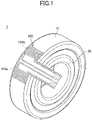
- Fig. 1 is a perspective view of an example of a rolling bearing according to a first embodiment.
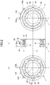
- Fig. 2 is a diagram illustrating an example of the rolling bearing according to the first embodiment.
- (a) of Fig. 2 is a front view of the rolling bearing
- (b) of Fig. 2 is a cross-sectional view of the rolling bearing
- (c) of Fig. 2 is a back view of the rolling bearing.
- a rolling bearing 1 includes an outer ring 10, an inner ring 20, multiple rolling elements 30, a holder 40, seals 51 and 52, and a strain gauge 100.
- illustration of the seals 51 and 52 are omitted for the sake of convenience.
- the outer ring 10 has a cylindrical structure of which a central axis is a rotation axis m.
- the inner ring 20 has a cylindrical structure that is disposed coaxially with the outer ring 10 and that is provided on an inner peripheral side of the outer ring 10.
- Each of the rolling elements 30 is a sphere disposed in a race 70 formed between the outer ring 10 and the inner ring 20.
- a lubricant (not illustrated) such as grease is applied to the race 70.
- the seals 51 and 52 protrude from the inner peripheral surface of the outer ring 10 toward the inner ring 20 to isolate the race 70 from the outside.
- a recessed portion 11 of which a cross-sectional shape is an arc shape is formed in a circumferential direction of the outer ring 10.
- a recessed portion 21 of which a cross-sectional shape is an arc shape is formed in a circumferential direction of the inner ring 20 and on an outer peripheral surface of the inner ring 20.
- the rolling elements 30 are guided in the circumferential direction by the recessed portions 11 and 21.
- the holder 40 is disposed in the race 70 to hold the rolling elements 30.
- the holder 40 is an annular element disposed coaxially with the rotation axis m.
- One side of the holder 40 in a direction of the rotation axis m includes recessed portions 41 for accommodating the respective rolling elements 30, and the other side of the holder 40 includes a back surface 42 continuously provided in a circumferential direction of the annular element.
- a strain gauge 100 is a sensor that detects strain of the outer ring 10 or the inner ring 20, and includes sensitive portions that are a resistor 103a and a resistor 103b.
- the strain gauge 100 is attached to the outer peripheral surface of the outer ring 10, and detects strain of the outer ring 10 as changes in resistance values of the resistor 103a and the resistor 103b.
- the resistor 103a and the resistor 103b are arranged in the same direction as an arrangement direction of the rolling elements 30, so as to correspond to spacing of rolling elements 30 that are next to each other.
- the resistors when the resistors are arranged so as to correspond to spacing of rolling elements that are next to each other, it means that, when a predetermined resistor-placement region intersects a given one straight line, a resistor-placement region next to the predetermined resistor-placement region is at a location intersecting a given straight line next to the given one straight line, where a rolling bearing including the resistors is not in operation under a condition in which straight lines passing the centers of the respective rolling elements are radially drawn from the rotation axis m of the rolling bearing when the rolling bearing is viewed in a front direction.
- the resistor-placement region corresponds to a range defined under a condition of a gauge length ⁇ a gauge width. From the viewpoint of detection sensitivity, it is preferable that a given straight line next to a given straight line passes near the center of a corresponding resistor-placement region next to the resistor-placement region.
- the resistors 103a and 103b of which a longitudinal direction (longitudinal direction of a gauge) of each is directed to a circumferential direction of the outer ring 10 is disposed.
- the outer ring 10 in the circumferential direction thereof is likely to be stretched and contracted in comparison to the outer ring in an axial direction thereof, and thus by disposing the resistors of which the longitudinal direction of each is directed to the circumferential direction of the outer ring 10, a great distorted waveform can be obtained.
- resistors 103a and 103b need not to be particularly distinguished, they may be referred to as resistors 103.
- strain gauge 100 By monitoring the output of the strain gauge 100 through an external device, a wear state of the rolling bearing 1 can be monitored.
- the strain gauge 100 will be described below in detail.
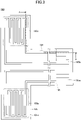
- Fig. 3 is a plan view of an example of the strain gauge according to the first embodiment.
- Fig. 4 is a cross-sectional view of an example of the strain gauge according to the first embodiment, and illustrates a cross section taken along the A-A line in Fig. 3 .
- the strain gauge 100 includes a substrate 101, a functional layer 102, the resistors 103a and 103b, lines 104, and terminal sections 105a and 105b.
- the functional layer 102 may be provided as needed.
- the side of the substrate 101 where the resistors 103 are provided is referred to as an upper side or one side, and the side of the substrate 101 where the resistors 103 are not provided is referred to as a lower side or another side.
- the surface on the side where the resistors 103 are provided is referred to as one surface or an upper surface, and the surface on the side where the resistors 103 are not provided is referred to as another surface or a lower surface.
- the strain gauge 100 can be used in a state of being upside down, or can be disposed at any angle.
- a plan view means that an object is viewed from a direction normal to an upper surface 101a of the substrate 101, and a planar shape refers to a shape of an object when viewed from the direction normal to the upper surface 101a of the substrate 101.
- the substrate 101 is a member that is a base layer for forming the resistors 103 or the like and is flexible.
- the thickness of the substrate 101 is not particularly restricted, and can be appropriately selected for any purpose. For example, such a thickness can be approximately between 5 ⁇ m and 500 ⁇ m. In particular, when the thickness of the substrate 101 is between 5 ⁇ m and 200 ⁇ m, it is preferable in terms of strain transfer from a flexure element surface that is bonded to a lower surface of the substrate 101 via an adhesive layer or the like, and dimensional stability with respect to environment, and when the thickness is 10 ⁇ m or more, it is further preferable in terms of insulation.
- the substrate 101 can be formed of an insulating resin film such as a polyimide (PI) resin, an epoxy resin, a polyether ether ketone (PEEK) resin, a polyethylene naphthalate (PEN) resin, a polyethylene terephthalate (PET) resin, a polyphenylene sulfide (PPS) resin, or a polyolefin resin.
- PI polyimide
- PEEK polyether ether ketone
- PEN polyethylene naphthalate
- PET polyethylene terephthalate
- PPS polyphenylene sulfide
- the film refers to a flexible member having a thickness of about 500 ⁇ m or less.
- the "formed of an insulating resin film” is not intended to preclude the substrate 101 from containing fillers, impurities, or the like in the insulating resin film.
- the substrate 101 may be formed of, for example, an insulating resin film containing fillers such as silica or alumina.
- the functional layer 102 is formed, as a lower layer of the resistors 103, on the upper surface 101a of the substrate 101.
- the planar shape of the functional layer 102 is approximately the same as the planar shape of the resistors 103 illustrated in Fig. 3 .
- the thickness of the functional layer 102 may be, for example, about 1 nm to 100 nm.
- the functional layer refers to a layer that has a function of promoting crystal growth of the resistors 103 that are at least an upper layer.
- the functional layer 102 preferably further has a function of preventing oxidation of the resistors 103 caused by oxygen and moisture included in the substrate 101, as well as a function of improving adhesion between the substrate 101 and each resistor 103.
- the functional layer 102 may further have other functions.
- the insulating resin film that constitutes the substrate 101 contains oxygen and moisture.
- each resistor 103 includes Cr (chromium)
- the material of the functional layer 102 is not particularly restricted as long as it is material having a function of promoting crystal growth of the resistors 103 that is at least an upper layer.
- Such material can be appropriately selected for any purpose, and includes one or more types of metals selected from the group consisting of, for example, Cr (chromium), Ti (titanium), V (vanadium), Nb (niobium), Ta (tantalum), Ni (nickel), Y (yttrium), Zr (zirconium), Hf (hafnium), Si (silicon), C (carbon), Zn (zinc), Cu (copper), Bi (bismuth), Fe (iron), Mo (molybdenum), W (tungsten), Ru (ruthenium), Rh (rhodium), Re (rhenium), Os (osmium), Ir (iridium), Pt (platinum), Pd (palladium), Ag (silver), Au (gold), Co (cobalt), Mn (manganese), and Al
- Examples of the above alloy include FeCr, TiAl, FeNi, NiCr, CrCu, and the like.
- Examples of the above compound include TiN, TaN, Si 3 N 4 , TiO 2 , Ta 2 O 5 , SiO 2 , and the like.
- Each resistor 103 is a thin film formed in a predetermined pattern, on the upper surface of the functional layer 102, and is a sensitive portion at which resistance changes in accordance with strain.
- the resistors 103 can be each formed of, for example, material including Cr (chromium), material including Ni (nickel), or material including both of Cr and Ni. In other words, the resistors 103 can be each formed of material including at least one from among Cr and Ni.
- An example of the material including Cr includes a Cr composite film.
- An example of the material including Ni includes Cu-Ni (copper nickel).
- An example of the material including both of Cr and Ni includes Ni-Cr (nickel chromium).
- each resistor 103 will be described as a Cr composite film.
- the Cr composite film is a composite film of Cr, CrN, Cr 2 N, and the like.
- the Cr composite film may include incidental impurities such as chromium oxide.
- a portion of the material constituting the functional layer 102 may be diffused into the Cr composite film.
- the material constituting the functional layer 102 and nitrogen may form a compound.
- the Cr composite film may include Ti or TiN (titanium nitride).
- each resistor 103 is not particularly restricted, and can be appropriately selected for any purpose.
- the thickness can be, for example, approximately between 0.05 ⁇ m and 2 ⁇ m.
- the thickness of the resistor 103 is 0.1 ⁇ m or more, it is preferable in terms of increases in crystallinity (e.g., crystallinity of ⁇ -Cr) of a crystal that constitutes the resistor 103.
- the thickness of the resistor 103 is 1 ⁇ m or less, it is further preferable in terms of reductions in cracks of a given film caused by internal stress of the film that constitutes the resistor 103, or reductions in warp in the substrate 101.
- the resistors 103a and 103b can be formed by a stable crystalline phase and thus stability of gauge characteristics (a gauge factor, a gauge factor temperature coefficient TCS, and a temperature coefficient of resistance TCR) can be increased.
- each resistor 103 is the Cr composite film
- the resistor 103 can be formed with ⁇ -Cr (alpha-chromium) as the main component.
- ⁇ -Cr alpha-chromium
- the ⁇ -Cr has a stable crystalline phase and thus stability of gauge characteristics can be increased.
- a main component means that a target substance is 50% by weight or more of total substances that constitute the resistor.
- the resistor 103 preferably includes ⁇ -Cr at 80% by weight or more, from the viewpoint of increasing the gauge characteristics. Note that ⁇ -Cr is Cr having a bcc structure (body-centered cubic structure).
- the gauge characteristics can be increased.
- the gauge factor of the strain gauge 100 can be 10 or more, as well as the gauge factor temperature coefficient TCS and temperature coefficient of resistance TCR being each in the range of from -1000 ppm/°C to +1000 ppm/°C.
- the terminal sections 105a respectively extend from both end portions of the resistor 103a, via the lines 104 and are each wider than the resistor 103a and a given line 104 to be in an approximately rectangular shape, in a plan view.
- the terminal sections 105a are a pair of electrodes for externally outputting changes in a resistance value of the resistor 103a in accordance with strain, where, for example, a lead wire for an external connection, or the like is joined.
- the resistor 103a extends from one terminal section 105a and one line 104, with zigzagged hairpin turns, to be connected to another line 104 and another terminal section 105a.
- the upper surface of each terminal section 105a may be coated with a metal allowing for greater solderability than the terminal section 105a.
- the terminal sections 105b respectively extend from both end portions of the resistor 103b, via the lines 104 and are each wider than the resistor 103b and a given line 104 to be in an approximately rectangular shape, in a plan view.
- the terminal sections 105b are a pair of electrodes for externally outputting changes in a resistance value of the resistor 103b in accordance with strain, where, for example, a lead wire for an external connection, or the like is joined.
- the resistor 103b extends from one terminal section 105b and one line 104, with zigzagged hairpin turns, to be connected to another line 104 and another terminal section 105b.
- the upper surface of each terminal section 105b may be coated with a metal allowing for greater solderability than the terminal section 105b.
- the resistors 103a and 103b, the lines 104, and the terminal sections 105a and 105b are expressed by different numerals.
- the resistors, the lines, and the terminal sections can be integrally formed of the same material, in the same process.
- terminal sections 105a and 105b need not to be particularly distinguished, they may be referred to as terminal sections 105.
- a cover layer 106 (insulating resin layer) may be provided on and above the upper surface 101a of the substrate 101, such that the resistors 103 and the lines 104 are coated and the terminal sections 105 are exposed. By providing the cover layer 106, mechanical damage and the like can be prevented from occurring in the resistors 103 and the lines 104. Also, by providing the cover layer 106, the resistors 103 and the lines 104 can be protected against moisture and the like.
- the cover layer 106 may be provided to cover all portions except for the terminal sections 105.
- the cover layer 106 can be formed of an insulating resin such as a PI resin, an epoxy resin, a PEEK resin, a PEN resin, a PET resin, or a PPS resin, a composite resin (e.g., a silicone resin or a polyolefin resin).
- the cover layer 106 may contain fillers or pigments.
- the thickness of the cover layer 106 is not particularly restricted, and can be appropriately selected for any purpose. For example, the thickness may be approximately between 2 ⁇ m and 30 ⁇ m.
- the substrate 101 is prepared and the functional layer 102 is formed on the upper surface 101a of the substrate 101.
- the material and thickness for each of the substrate 101 and the functional layer 102 are the same as the material and thickness described above.
- the functional layer 102 may be provided as necessary.
- the functional layer 102 can be vacuum-deposited by, for example, conventional sputtering in which a raw material capable of forming the functional layer 102 is a target and in which an Ar (argon) gas is supplied to a chamber.
- Ar argon
- the functional layer 102 is deposited while the upper surface 101a of the substrate 101 is etched with Ar.
- a deposited amount of film of the functional layer 102 is minimized and thus an effect of increasing adhesion can be obtained.
- the functional layer 102 may be formed by other methods.
- the upper surface 101a of the substrate 101 is activated by plasma treatment or the like using Ar or the like to thereby obtain the effect of increasing the adhesion, and subsequently the functional layer 102 may be vacuum-deposited by magnetron sputtering.
- a metallic layer that includes the resistors 103, the lines 104, and the terminal sections 105 is formed on the entire upper surface of the functional layer 102, and then the functional layer 102, the resistors 103, the lines 104, and the terminal sections 105 are each patterned in the planar shape as illustrated in Fig. 3 , by photolithography.
- the material and thickness for each of the resistors 103, the lines 104, and the terminal sections 105 are the same as the material and thickness described above.
- the resistors 103, the lines 104, and the terminal sections 105 can be integrally formed of the same material.
- the resistors 103, the lines 104, and the terminal sections 105 can be deposited by, for example, magnetron sputtering in which a raw material capable of forming the resistors 103, the lines 104, and the terminal sections 105 is a target.
- the resistors 103, the lines 104, and the terminal sections 105 may be deposited by reactive sputtering, vapor deposition, arc ion plating, pulsed laser deposition, or the like.
- a combination of the material of the functional layer 102 and the material of the resistors 103, the lines 104, and the terminal sections 105 is not particularly restricted, and can be appropriately selected for any purpose.
- Ti is used for the functional layer 102, and a Cr composite film formed with ⁇ -Cr (alpha-chromium) as the main component can be deposited as the resistors 103, the lines 104, and the terminal sections 105.
- each of the resistors 103, the lines 104, and the terminal sections 105 can be deposited by, for example, magnetron sputtering in which a raw material capable of forming the Cr composite film is the target and in which an Ar gas is supplied to a chamber.
- the resistors 103, the lines 104, and the terminal sections 105 may be deposited by reactive sputtering in which pure Cr is the target and in which an appropriate amount of nitrogen gas, as well as an Ar gas, are supplied to a chamber.
- a growth face of the Cr composite film is defined by the functional layer 102 formed of Ti, and a Cr composite film that is formed with ⁇ -Cr as the main component having a stable crystalline structure can be deposited. Also, Ti that constitutes the functional layer 102 is diffused into the Cr composite film, so that the gauge characteristics are increased.
- the gauge factor of the strain gauge 100 can be 10 or more, as well as the gauge factor temperature coefficient TCS and temperature coefficient of resistance TCR being each in the range of from -1000 ppm/° C to +1000 ppm/° C.
- the functional layer 102 formed of Ti includes all functions of a function of promoting crystal growth of the resistor 103, a function of preventing oxidation of the resistor 103 caused by oxygen or moisture contained in the substrate 101, and a function of increasing adhesion between the substrate 101 and the resistor 103.
- the functional layer 102 is formed of Ta, Si, Al, or Fe, the functional layer also includes the same functions.
- the cover layer 106 with which the resistors 103 and the lines 104 are coated and that exposes the terminal sections 105 is provided on and above the upper surface 101a of the substrate 101, as necessary, so that the strain gauge 100 is completed.
- the cover layer 106 can be fabricated such that a thermosetting insulating resin film in a semi-cured state is laminated on the upper surface 101a of the substrate 101, and such that the resistors 103 and the lines 104 are coated and the terminal sections 105 are exposed; subsequently, heat is added and curing is performed.
- the cover layer 106 may be formed such that a thermosetting insulating resin that is liquid or paste-like is applied to the upper surface 101a of the substrate 101, and such that the resistors 103 and the lines 104 are coated therewith and the terminal sections 105 are exposed; subsequently, heat is added and curing is performed.
- the functional layer 102 in the lower layer of the resistors 103, the crystal growth of the resistors 103 can be promoted and thus the resistors 103 having a stable crystalline phase can be fabricated.
- the stability of the gauge characteristics can be increased.
- the material that constitutes the functional layer 102 is diffused into the resistors 103, so that the gauge characteristics of the strain gauge 100 can be thereby increased.
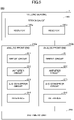
- Fig. 5 is a block diagram illustrating an example of a bearing monitoring apparatus according to the first embodiment.
- a bearing monitoring apparatus 200 includes the rolling bearing 1, analog front ends 210a and 210b, and an arithmetic unit 220.
- a pair of terminal sections 105a in the strain gauge 100 for the rolling bearing 1 are connected to the analog front end 210a by using, for example, a flexible substrate, a lead wire, or the like.
- the analog front end 210a includes, for example, a bridge circuit 211, an amplifier circuit 212, an A/D converter circuit (analog-to-digital converter circuit) 213, an interface 214, and the like, and generates a first distorted waveform based on the output of the resistor 103a.
- the analog front end 210a may include a temperature compensating circuit.
- the analog front end 210a may be constituted by one or more ICs, or may be configured by individual components.
- the pair of terminal sections 105a in the strain gauge 100 is connected to the bridge circuit 211.
- one side of the bridge circuit 211 is constituted by the resistor 103a between the pair of terminal sections 105a, and the other three sides are each constituted by fixed resistance.
- the first distorted waveform (analog signal) corresponding to a resistance value of the resistor 103a can be obtained as the output of the bridge circuit 211.
- the analog front end 210a is a representative example of a waveform generator according to the present invention.
- the analog front end 210a After the first distorted waveform output from the bridge circuit 211 is amplified by the amplifier circuit 212, the amplified first distorted waveform is converted into a digital signal by the A/D converter circuit 213. Then, the digital signal is output to the arithmetic unit 220 through the interface 214 by serial communication such as I 2 C.
- the analog front end 210a includes a temperature compensating circuit, a temperature-compensated digital signal is transmitted to the arithmetic unit 220.
- a pair of terminal sections 105b of the strain gauge 100 for the rolling bearing 1 is connected to the analog front end 210b by using, for example, a flexible substrate, a lead line, or the like.
- the analog front end 210b has the same function as the analog front end 210a, and generates a second distorted waveform based on the output of the resistor 103b.
- the analog front end 210b, as the analog front end 210a, may be formed as one IC.
- the pair of terminal sections 105b in the strain gauge 100 is connected to a bridge circuit 211.
- one side of the bridge circuit 211 is constituted by the resistor 103b between the pair of terminal sections 105b, and the other three sides are each constituted by fixed resistance.
- the second distorted waveform (analog signal) corresponding to a resistance value of the resistor 103b can be obtained as the output of the bridge circuit 211.
- the analog front end 210b is a representative example of a waveform generator according to the present invention.
- the analog front end 210b After the second distorted waveform output from the bridge circuit 211 is amplified by the amplifier circuit 212, the amplified second distorted waveform is converted into a digital signal by the A/D converter circuit 213. Then, the digital signal is output to the arithmetic unit 220 through the interface 214 by serial communication such as I 2 C.
- the analog front end 210b includes a temperature compensating circuit, a temperature-compensated digital signal is transmitted to the arithmetic unit 220.
- the arithmetic unit 220 performs arithmetic processing with respect to digitized first and second distorted waveforms that are respectively transmitted from the analog front ends 210a and 210b, and monitors a wear state of the rolling bearing 1. For example, the arithmetic unit 220 monitors a wear state of the rolling bearing 1, based on the amplitude or period of the digitalized distorted waveforms.
- the arithmetic processing includes, for example, subtracting of the second distorted waveform from the first distorted waveform to thereby generate a differential waveform, or comparing of the differential waveform against a reference value.
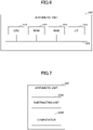
- Fig. 6 is a hardware block diagram of an example of the arithmetic unit according to the first embodiment.
- the arithmetic unit 220 includes main components that are a central processing unit (CPU) 221, a read only memory (ROM) 222, a random access memory (RAM) 223, an interface (I/F) 224, and a bus line 225.
- the CPU 221, the ROM 222, the RAM 223, and the I/F 224 are interconnected via the bus line 225.
- the arithmetic unit 220 may have another hardware block as necessary.
- the CPU 221 controls each function of the arithmetic unit 220.
- the ROM 222 which is a storage device, stores a program that causes the CPU 221 to control each function of the arithmetic unit 220, as well as storing various information.
- the RAM 223, which is a storage device, is used as a work area or the like of the CPU 221.
- the RAM 223 can temporarily store predetermined information.
- the I/F 224 is an interface for coupling to another device or the like. For example, the I/F 224 is coupled with the analog front ends 210a and 210b, an external network, or the like.
- the arithmetic unit 220 may be a processor programmed to implement each function by software, as in a processor that is implemented by an electronic circuit.
- the arithmetic unit 220 may include an application specific integrated circuit (ASIC) designed to implement a predetermined function.
- the arithmetic unit 220 may include a digital signal processor (DSP), a field programmable gate array (FPGA), a system on a chip (SOC), or a graphics processing unit (GPU).
- DSP digital signal processor
- FPGA field programmable gate array
- SOC system on a chip
- GPU graphics processing unit
- the arithmetic unit 220 may be a circuit module or the like.
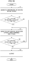
- Fig. 7 is a functional block diagram of an example of the arithmetic unit according to the first embodiment.
- the arithmetic unit 220 includes main functional blocks that are a subtracting unit 2201 and a comparator 2202.
- the arithmetic unit 220 may include another functional block as necessary.
- the subtracting unit 2201 includes a function of subtracting the second distorted waveform from the digitalized first distorted waveform to generate a differential waveform between the first distorted waveform and the second distorted waveform.
- the comparator 2202 includes a function of comparing the differential waveform generated by the subtracting unit 2201, against a predetermined reference value.
- the arithmetic unit 220 may have another function as necessary.
- Fig. 8 is a diagram illustrating an example of initial distorted waveforms generated by the analog front end.
- Fig. 8 illustrates a first distorted waveform (A1), a second distorted waveform (B1), and a differential waveform (C1).
- distorted waveforms are periodic waveforms of which peaks and bottoms are repeated.
- the peak for a strain amount output intensity
- the bottom is obtained at an intermediate position between rolling elements 30 that are next to each other.
- a rotation speed of the rolling bearing 1 can be determined by detecting the number of peaks for the strain amount that appear during a fixed time period.
- the output of the differential waveform (C1) that is obtained by subtracting the second distorted waveform (B1) from the first distorted waveform (A1) is approximately zero.
- Fig. 9 illustrates distorted waveforms generated by the analog front end after the passage of a predetermined time period.
- Fig. 9 illustrates a first distorted waveform (A2), a second distorted waveform (B2), and a differential waveform (C2).
- the differential waveform (C2) that is obtained by subtracting the second distorted waveform (B2) from the first distorted waveform (A2) is not approximately zero, and consequently the waveform of which output intensity varies greatly is obtained.
- each of the amplitude and period of a given distorted waveform varies due to wearing of the race or one or more rolling elements.
- the arithmetic unit 220 can monitor a wear state of the rolling bearing 1, based on the differential waveform.
- Fig. 10 is a flowchart illustrating an example of the method for monitoring a bearing executed by the bearing monitoring apparatus according to the first embodiment.
- the subtracting unit 2201 obtains, from the analog front ends 210a and 210b, data indicating an initial first distorted waveform and second distorted waveform, subtracts the second distorted waveform from the first distorted waveform, and generates an initial differential waveform.
- step S2 the comparator 2202 compares the initial differential waveform against each of thresholds Th1 and Th2, and detects a wear state of the rolling bearing 1.
- the thresholds Th1 and Th2 are set taking into account a wear state to be detected, and are preliminarily stored in the RAM or the like.
- step S2 if the differential waveform exceeds at least one among the thresholds Th1 and Th2 (NO), the process proceeds to step S5, and then the comparator 2202 outputs an indication that an initial failure occurs (data output, generation of an alarm sound, lighting of a warning light, or the like).
- step S2 if the differential waveform is less than or equal to each of the thresholds Th1 and Th2 (YES), the process proceeds to step S3.
- step S2 if the waveforms illustrated in Fig. 8 are obtained, the differential waveform (C1) is less than or equal to each of the thresholds Th1 and Th2. Thus, it is confirmed that the wear state of the rolling bearing 1 is not abnormal in an initial stage and the rolling bearing 1 is operated normally. In this case, the process proceeds to step S3.
- step S3 the subtracting unit 2201 obtains data indicative of the first distorted waveform and second distorted waveform after the passage of a predetermined time period.
- the subtracting unit 2201 subtracts the second distorted waveform from the first distorted waveform, and generates the differential waveform after the passage of the predetermined time period.
- step S4 the comparator 2202 compares, against each of the thresholds Th1 and Th2, the differential waveform after the passage of the predetermined time period, and detects the wear state of the rolling bearing 1.
- step S4 if the differential waveform exceeds at least one among the thresholds Th1 and Th2 (NO), the process proceeds to step S5, and then the comparator 2202 externally outputs an indication that the rolling bearing 1 becomes at a wear state that is preset (data output, generation of an alarm sound, lighting of a warning light, or the like).
- step S4 if the differential waveform is less than or equal to each of the thresholds Th1 and Th2 (YES), the process proceeds to step S3 again, and then each of the subtracting unit 2201 and the comparator 2202 repeats the above-described operation.
- step S4 if the waveforms illustrated in Fig. 9 are obtained, the rolling bearing 1 at such a timing becomes at the preset wear state, because the differential waveform (C2) exceeds the threshold Th1. In this case, the process proceeds to step S5, and then the comparator 2202 externally outputs an indication that the rolling bearing 1 becomes at the preset wear state (data output, generation of an alarm sound, lighting of a warning light, or the like) .
- the above-mentioned criteria for determining wearing is one example, and there is no limitation to the example described above. For example, if the number of times that the differential waveform exceeds both the thresholds Th1 and Th2 is one or more, the rolling bearing 1 may be determined to become at a determined wear state. If the number of times that the differential waveform exceeds both the thresholds is a predetermined number or more, the rolling bearing 1 may be determined to become at a determined wear state. Another determination criteria may be adopted.
- each of the thresholds Th1 and Th2 is an example of a reference value for comparison with the differential waveform after the passage of a predetermined time period.
- the initial differential waveform is used as a reference value, and if the change from the initial differential waveform, to the differential waveform obtained after the passage of a predetermined time period, is greater than or equal to a predetermined level, it may be determined that a predetermined wear state is reached.
- the strain gauge 100 using a Cr composite film as the material of the resistor 103 becomes highly sensitive (500% or more compared to conventional strain gauges) and is made compact (1/10 or less compared to the conventional strain gauges).
- the output of the conventional strain gauges is about 0.04 mV / 2 V, while the output of the strain gauge 100 can be 0.3 mV / 2 V or more.
- the size (gauge length ⁇ gauge width) of the conventional strain gauges is about 3 mm ⁇ 3 mm, while the size (gauge length ⁇ gauge width) of the strain gauge 100 can be reduced to about 0.3 mm ⁇ 0.3 mm.
- the strain gauge 100 using the Cr composite film as the material of the resistor 103 is made compact, and thus the strain gauge 100 can be easily attached to a desired location of the rolling bearing 1. Also, the strain gauge 100 using the Cr composite film as the material of the resistor 103 is highly sensitive and thus small displacement can be detected. Accordingly, minute strain, which was difficult to be detected in the past, can be detected. In other words, with use of the strain gauge 100 using the Cr composite film as the material of the resistor 103, the rolling bearing 1 having a function of accurately detecting strain can be achieved. As a result, the bearing monitoring apparatus 200 that can detect a wear state of the rolling bearing 1 can be achieved.
- the strain gauge 100 is disposed on the inner peripheral surface or end surface of the inner ring 20, and if the inner ring 20 rotates, the strain gauge 100 is disposed on the outer peripheral surface or end surface of the outer ring 10.
- the description above provides an example in which the strain gauge 100 is attached to the outer ring 10, where the inner ring 20 rotates. If the outer ring 10 in the rolling bearing 1 rotates, the strain gauge 100 is attached to the inner ring 20, thereby obtaining the same effect as that described above. The same applies to the following embodiments.
- the modification of the first embodiment provides an example of the rolling bearing having the strain gauge, which differs from that according to the first embodiment.
- the description for the same components as those that have been described in the embodiment may be omitted.
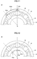
- Fig. 11 is a partial front view of an example of the rolling bearing according to a first modification of the first embodiment.
- a rolling bearing 1A differs from the rolling bearing 1 (see Fig. 2 and the like) in that a strain gauge 100A is used instead of the strain gauge 100.
- the strain gauge 100A is disposed in a circumferential direction of the outer ring 10 so as to be along one end surface of the outer ring.
- the strain gauge 100A has the same configuration as the strain gauge 100, and is formed to have the shape that can be attached to the end surface of the outer ring 10.
- the resistors 103a and 103b are arranged in an arrangement direction of rolling elements 30, so as to correspond to spacing between given rolling elements 30 that are next to each other.
- the resistors serving as sensitive portions may be disposed on the end surface of the outer ring 10, instead of the outer peripheral surface of the outer ring 10.
- the strain gauge 100A is used instead of the strain gauge 100, and thus the wear state of the rolling bearing 1A can be monitored as in the rolling bearing 1.
- Fig. 12 is a partial front view of an example of the rolling bearing according to a second modification of the first embodiment.
- a rolling bearing 1B differs from the rolling bearing 1 (see Fig. 2 and the like) in that a strain gauge 100B is used instead of the strain gauge 100.
- the strain gauge 100B is disposed in a circumferential direction of the inner ring 20 so as to be along an inner peripheral surface of the inner ring.
- the strain gauge 100B has the same configuration as the strain gauge 100, and is formed to have the shape that can be attached to the inner peripheral surface of the inner ring 20.
- the resistors 103a and 103b are arranged in an arrangement direction of rolling elements 30, so as to correspond to spacing between given rolling elements 30 that are next to each other.
- the resistors serving as sensitive portions may be disposed on the inner peripheral surface of the inner ring 20, instead of the outer peripheral surface of the outer ring 10.
- the strain gauge 100B is used instead of the strain gauge 100, and thus the wear state of the rolling bearing 1B can be monitored as in the rolling bearing 1.
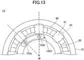
- Fig. 13 is a partial front view of an example of the rolling bearing according to a third modification of the first embodiment.
- a rolling bearing 1C differs from the rolling bearing 1 (see Fig. 2 and the like) in that a strain gauge 100C is used instead of the strain gauge 100.
- the strain gauge 100B is disposed in a circumferential direction of the inner ring 20 so as to be along an end surface of the inner ring.
- the strain gauge 100C has the same configuration as the strain gauge 100, and is formed to have the shape that can be attached to one end surface of the inner ring 20.
- the resistors 103a and 103b are arranged in an arrangement direction of rolling elements 30, so as to correspond to spacing between given rolling elements 30 that are next to each other.
- the resistors serving as sensitive portions may be disposed on the end surface of the inner ring 20, instead of the outer peripheral surface of the outer ring 10.
- the strain gauge 100C is used instead of the strain gauge 100, and thus the wear state of the rolling bearing 1C can be monitored as in the rolling bearing 1.
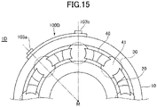
- Fig. 14 is a perspective view of an example of the rolling bearing according to a fourth modification of the first embodiment.
- Fig. 15 is a partial front view of an example of the rolling bearing according to the fourth modification of the first embodiment.
- a rolling bearing 1D differs from the rolling bearing 1 (see Fig. 2 and the like) in that a strain gauge 100D is used instead of the strain gauge 100.
- a preload F is applied to the rolling bearing 1D in a direction, as expressed by the arrow, parallel to the axis of the rolling bearing.
- the strain gauge 100D is disposed on the side of the outer peripheral surface of the outer ring 10 opposite the preload.
- the resistors 103a and 103b are arranged in the same direction as the arrangement direction of rolling elements 30, so as to correspond to spacing between given rolling elements 30 that are next to each other.
- the outer peripheral surface of the rolling bearing 1D is held by the inner peripheral surface of a housing (casing) by contact with the inner peripheral surface of the housing.
- an undercut is provided on the housing side, with respect to a providing portion of the strain gauge 100D, such that the strain gauge 100D does not contact the housing.
- the outer peripheral surface of the rolling bearing 1D is not held by the inner peripheral surface of the housing, by contact with the inner peripheral surface of the housing.
- the outer peripheral surface of the rolling bearing directly above the rolling element 30 is to be greatly distorted.
- the outer peripheral surface of the outer ring 10 located directly above a given rolling element 30 is held by the inner peripheral surface of the housing, by contact with inner peripheral surface of the housing, over the whole circumference of the outer ring.
- the preload F is applied to the rolling bearing 1D, and thus the rolling elements 30 are distributed toward a direction opposite the direction expressed by the arrow, with respect to a middle portion of the outer ring 10 in a thickness direction of the outer ring.
- the resistors 103a and 103b are disposed on the side of the outer peripheral surface of the outer ring 10 opposite the preload, when undercuts of the housing are respectively provided with respect to only portions of the resistors 103a and 103b, they are sufficient.
- the outer peripheral surface of the outer ring 10 located directly above the rolling element 30 can be held by the inner peripheral surface of the housing, by contact with the inner peripheral surface of the housing, over the whole circumference of the outer ring.
- a recessed portion at which a given strain gauge is disposed is also considered to be provided in the outer ring 10 or the inner ring 20.
- strain gauge 100D Greatest strain to be detected by the strain gauge 100D is obtained at the outer peripheral surface of the outer ring 10 that is located directly above each rolling element 30, and small strain is obtained on the side of the outer ring 10 opposite the preload, in comparison to a case of strain obtained directly above each rolling element 30.
- a conventional strain gauge is disposed on the side of the outer peripheral surface of the outer ring 10 opposite the preload, it has been difficult to obtain a distorted waveform.
- the strain gauge 100B that uses the Cr composite film as each resistor is highly sensitive and thus can detect small displacement. Therefore, even if the strain gauge 100D is disposed on the side of the outer peripheral surface of the outer ring 10 opposite the preload, a distorted waveform can be accurately obtained.
- a second embodiment provides an example of the rolling bearing having the housing outside the outer ring.
- the description for the same components as those that have been described in the embodiment may be omitted.
- Fig. 16 is a perspective view of an example of the rolling bearing according to the second embodiment.
- Fig. 17 is a partial front view of an example of the rolling bearing according to the second embodiment.
- a rolling bearing 1E includes a housing 60 disposed on an outer peripheral side of the outer ring 10, and the strain gauge 100 is disposed on the outer peripheral surface of the housing 60.
- the housing 60 holds the outer peripheral surface of the outer ring 10 over the whole circumference of the outer ring.
- the housing 60 can be formed of, for example, brass or the like.
- the outer ring 10 has a small diameter (e.g., diameter of about 20 mm) and thus it might be difficult to dispose the strain gauge 100 on the outer ring 10.
- the strain gauge 100 may be disposed on a given end surface of the housing 60. With this arrangement, the strain gauge 100 can be easily disposed. The strain of the outer ring 10 is transferred through the housing 60 to the strain gauge 100 and is detectable by the strain gauge 100.
- the strain gauge 100 using the Cr composite film as the material of the resistor 103 is highly sensitive, and can detect small displacement. Thus, minute strain, which was difficult to be detected in the past, can be detected.
- the rolling bearing 1E having a function for accurately detecting strain can be achieved. As a result, even when the strain gauge 100 is disposed on the housing 60, a bearing monitoring apparatus 200 that can detect a wear state of the rolling bearing 1E can be provided.
- the shape of the housing is not limited to an annular shape, and any shape may be adopted.
- the housing 60 may also serve as a housing for the rotating apparatus.
- a given strain gauge may be disposed on an outer peripheral surface or end surface of the housing for the rotating apparatus.
Landscapes
- Engineering & Computer Science (AREA)
- General Engineering & Computer Science (AREA)
- Mechanical Engineering (AREA)
- Physics & Mathematics (AREA)
- General Physics & Mathematics (AREA)
- Chemical & Material Sciences (AREA)
- Analytical Chemistry (AREA)
- Acoustics & Sound (AREA)
- Measurement Of Length, Angles, Or The Like Using Electric Or Magnetic Means (AREA)
- Testing Of Devices, Machine Parts, Or Other Structures Thereof (AREA)
- Rolling Contact Bearings (AREA)
Claims (9)
- Lagerüberwachungsvorrichtung (200), umfassend:ein Wälzlager (1), das einschließteinen Außenring (10),einen Innenring (20), der mit dem Außenring koaxial angeordnet ist, wobei sich der Innenring auf einer Innenumfangsseite des Außenrings befindet,mehrere Wälzelemente (30), die zwischen dem Außenring und dem Innenring angeordnet sind, undeinen Dehnungsmesser (100), der konfiguriert ist, um die Dehnung des Außenrings oder des Innenrings zu erfassen, wobei der Dehnungsmesser mindestens zwei Widerstände (103a, 103b) einschließtund die Widerstände in einer gleichen Richtung wie eine Einrichtungsrichtung der Wälzelemente eingerichtet sind, umeinem Abstand zwischen Wälzelementen, die nebeneinander sind, zu entsprechen, dadurch gekennzeichnet, dass die Lagerüberwachungsvorrichtung ferner umfassteinen Wellenformgenerator, der konfiguriert ist, um eine erste verzerrte Wellenform basierend auf einer Ausgabe eines Widerstands zu erzeugen und eine zweite verzerrte Wellenform basierend auf einer Ausgabe eines anderen Widerstands zu erzeugen;eine Subtrahiereinheit (2201), die konfiguriert ist, um die zweite verzerrte Wellenform von der ersten verzerrten Wellenform zu subtrahieren, um eine Differenzialwellenform zu erzeugen; undeinen Vergleicher (2202), der konfiguriert ist, um die Differenzialwellenform mit einem Referenzwert zu vergleichen, um einen Verschleißzustand des Wälzlagers zu erfassen.
- Lagerüberwachungsvorrichtung nach Anspruch 1, wobei die mindestens zwei Widerstände in dem Wälzlager auf einer Außenumfangsoberfläche des Außenrings oder einer Innenumfangsoberfläche des Innenrings angeordnet sind.
- Lagerüberwachungsvorrichtung nach Anspruch 2, wobei die mindestens zwei Widerstände in dem Wälzlager auf einer Seite gegenüber einer Vorspannung angeordnet sind.
- Lagerüberwachungsvorrichtung nach Anspruch 1, wobei die mindestens zwei Widerstände in dem Wälzlager auf einer Endoberfläche des Außenrings oder einer Endoberfläche des Innenrings angeordnet sind.
- Lagerüberwachungsvorrichtung nach Anspruch 1, wobei das Wälzlager ein Gehäuse einschließt, das mit dem Außenumfang des Außenrings in Berührung angeordnet ist, und
wobei die mindestens zwei Widerstände auf einer Außenumfangsoberfläche des Gehäuses angeordnet sind. - Lagerüberwachungsvorrichtung nach Anspruch 1, wobei das Wälzlager ein Gehäuse einschließt, das mit dem Außenumfang des Außenrings in Berührung angeordnet ist, und
wobei die mindestens zwei Widerstände auf einer Endoberfläche des Gehäuses angeordnet sind. - Lagerüberwachungsvorrichtung nach einem der Ansprüche 1 bis 6, wobei die mindestens zwei Widerstände in dem Wälzlager derart eingerichtet sind, dass eine Längsrichtung jedes Widerstands auf eine Umfangsrichtung des Außenrings oder des Innenrings gerichtet ist.
- Lagerüberwachungsvorrichtung nach einem der Ansprüche 1 bis 7, wobei jeder der mindestens zwei Widerstände in dem Wälzlager aus einer Cr-Verbundfolie ausgebildet ist.
- Verfahren zum Überwachen eines Lagers (1), das Verfahren umfassend:Erzeugen einer ersten verzerrten Wellenform basierend auf einer Ausgabe eines Widerstands (103a) in einem Wälzlager, undErzeugen einer zweiten verzerrten Wellenform basierend auf einer Ausgabe eines anderen Widerstands (103b), wobei das Wälzlager einschließteinen Außenring (10),einen Innenring (20), der mit dem Außenring koaxial angeordnet ist, wobei sich der Innenring auf einer Innenumfangsseite des Außenrings befindet,mehrere Wälzelemente (30), die zwischen dem Außenring und dem Innenring angeordnet sind, undeinen Dehnungsmesser (100), der konfiguriert ist, um die Dehnung des Außenrings oder des Innenrings zu erfassen, wobei der Dehnungsmesser mindestens zwei Widerstände (103a, 103b) einschließt, und die Widerstände in einer gleichen Richtung wie eine Einrichtungsrichtung der Wälzelemente eingerichtet sind, um einem Abstand zwischen Wälzelementen, die nebeneinander sind, zu entsprechen;Subtrahieren der zweiten verzerrten Wellenform von der ersten verzerrten Wellenform, um eine Differenzialwellenform zu erzeugen; undVergleichen der Differenzialwellenform mit einem Referenzwert, um einen Verschleißzustand des Wälzlagers zu erfassen.
Applications Claiming Priority (2)
| Application Number | Priority Date | Filing Date | Title |
|---|---|---|---|
| JP2019115681A JP6986050B2 (ja) | 2019-06-21 | 2019-06-21 | 軸受監視装置、軸受監視方法 |
| PCT/JP2020/023073 WO2020255860A1 (ja) | 2019-06-21 | 2020-06-11 | 軸受監視装置、軸受監視方法 |
Publications (3)
| Publication Number | Publication Date |
|---|---|
| EP3971430A1 EP3971430A1 (de) | 2022-03-23 |
| EP3971430A4 EP3971430A4 (de) | 2022-07-13 |
| EP3971430B1 true EP3971430B1 (de) | 2023-01-11 |
Family
ID=73993977
Family Applications (1)
| Application Number | Title | Priority Date | Filing Date |
|---|---|---|---|
| EP20825459.9A Active EP3971430B1 (de) | 2019-06-21 | 2020-06-11 | Lagerüberwachungsvorrichtung und lagerüberwachungsverfahren |
Country Status (5)
| Country | Link |
|---|---|
| US (1) | US11867227B2 (de) |
| EP (1) | EP3971430B1 (de) |
| JP (1) | JP6986050B2 (de) |
| CN (1) | CN114080514B (de) |
| WO (1) | WO2020255860A1 (de) |
Families Citing this family (6)
| Publication number | Priority date | Publication date | Assignee | Title |
|---|---|---|---|---|
| WO2023276365A1 (ja) | 2021-07-02 | 2023-01-05 | ミネベアミツミ株式会社 | 転がり軸受 |
| CN113982864B (zh) * | 2021-12-03 | 2023-08-08 | 大连三环复合材料技术开发股份有限公司 | 一种风电机组主轴滑动轴承磨损量监测传感器 |
| JP2023141893A (ja) * | 2022-03-24 | 2023-10-05 | ミネベアミツミ株式会社 | センサユニット、軸受装置、ひずみ検出装置、モータ |
| JP2023141894A (ja) * | 2022-03-24 | 2023-10-05 | ミネベアミツミ株式会社 | センサユニット、軸受装置、ひずみ検出装置、モータ |
| JP2023166819A (ja) * | 2022-05-10 | 2023-11-22 | ミネベアミツミ株式会社 | 軸受装置、ひずみ検出装置 |
| CN117167408B (zh) * | 2023-09-04 | 2026-03-27 | 二重(德阳)重型装备有限公司 | 齿轮箱内轴承用智能化轴承套 |
Family Cites Families (46)
| Publication number | Priority date | Publication date | Assignee | Title |
|---|---|---|---|---|
| US4533414A (en) * | 1980-07-10 | 1985-08-06 | Cabot Corporation | Corrosion-resistance nickel alloy |
| GB2113845A (en) * | 1982-01-19 | 1983-08-10 | Standard Telephones Cables Ltd | Monitoring loads in rotating bearings |
| JP2533831B2 (ja) * | 1993-06-02 | 1996-09-11 | 工業技術院長 | センサ―付転がり軸受 |
| FR2708044B1 (fr) * | 1993-07-21 | 1995-09-01 | Snecma | Turbomachine comportant un dispositif de mesure de la poussée axiale d'un rotor. |
| DE10017572B4 (de) * | 2000-04-10 | 2008-04-17 | INSTITUT FüR MIKROTECHNIK MAINZ GMBH | Wälzlager mit fernabfragbaren Erfassungseinheiten |
| JP2001355632A (ja) * | 2000-06-15 | 2001-12-26 | Nsk Ltd | 転がり軸受の運転状態監視装置 |
| DE10041093A1 (de) * | 2000-08-22 | 2002-03-14 | Bosch Gmbh Robert | Sensoranordnung in einem Wälzlager und Verfahren zur Auswertung des Ausgangssignals der Sensoranordnung |
| EP1211500B1 (de) * | 2000-12-01 | 2009-09-02 | Nsk Ltd | Wälzlagervorrichtung mit Sensor |
| JP2003090335A (ja) * | 2000-12-01 | 2003-03-28 | Nsk Ltd | センサ付転がり軸受装置及びセンサ付回転支持装置 |
| JP2002357226A (ja) * | 2001-03-28 | 2002-12-13 | Nsk Ltd | 玉軸受 |
| US6802221B2 (en) * | 2001-03-29 | 2004-10-12 | General Electric Company | System and method for conditioned-based monitoring of a bearing assembly |
| US6711952B2 (en) * | 2001-10-05 | 2004-03-30 | General Electric Company | Method and system for monitoring bearings |
| JP4039070B2 (ja) * | 2002-02-05 | 2008-01-30 | 日本精工株式会社 | センサ付軸受装置 |
| JP2004218814A (ja) * | 2003-01-17 | 2004-08-05 | Nsk Ltd | 軸受装置 |
| DE10304592A1 (de) | 2003-02-05 | 2004-08-19 | Fag Kugelfischer Ag | Messlager mit integriertem Datenerfassungs- und verarbeitungssystems |
| JP2006030786A (ja) * | 2004-07-20 | 2006-02-02 | Kyocera Mita Corp | 画像形成装置 |
| DE102004037358B3 (de) | 2004-07-30 | 2006-03-23 | Fag Kugelfischer Ag & Co. Ohg | Verfahren und Computerprogrammprodukt zur Stillstandsdetektion eines Wälzlagers sowie Wälzlager |
| JPWO2006030786A1 (ja) * | 2004-09-13 | 2008-05-15 | 日本精工株式会社 | 異常診断装置及び異常診断方法 |
| JP4440129B2 (ja) * | 2005-02-04 | 2010-03-24 | 住友化学株式会社 | 較正曲線取得方法 |
| US7634913B2 (en) * | 2005-03-30 | 2009-12-22 | General Electric Company | Bearing assembly and method of monitoring same |
| JP2006307935A (ja) * | 2005-04-27 | 2006-11-09 | Jtekt Corp | センサ付転がり軸受装置 |
| JP2008164448A (ja) * | 2006-12-28 | 2008-07-17 | Ntn Corp | センサ付車輪用軸受 |
| FR2913769B1 (fr) * | 2007-03-12 | 2009-06-05 | Snecma Sa | Procede de detection d'un endommagement d'un roulement de palier d'un moteur |
| WO2009119068A1 (ja) * | 2008-03-26 | 2009-10-01 | Ntn株式会社 | センサ付車輪用軸受 |
| DE102008016592A1 (de) * | 2008-03-31 | 2009-10-01 | Bombardier Transportation Gmbh | Messlager |
| JP2012181169A (ja) * | 2011-03-03 | 2012-09-20 | Ntn Corp | 転動部品の状態監視装置および状態監視方法 |
| EP2708865B1 (de) * | 2011-05-09 | 2019-09-04 | NTN Corporation | Mit einem sensor ausgestattetes radlager |
| EP2623949A1 (de) * | 2012-01-31 | 2013-08-07 | Siemens Aktiengesellschaft | Zustandsüberwachungsvorrichtung und Verfahren zur Zustandsüberwachung von rotierenden mechanischen Bauteilen |
| KR20150004844A (ko) * | 2012-04-24 | 2015-01-13 | 아크티에볼라게트 에스케이에프 | 베어링 모니터링 방법 및 시스템 |
| EP2841781B1 (de) * | 2012-04-24 | 2018-01-10 | Aktiebolaget SKF (publ) | Modul zur bestimmung einer betriebsgrösse eines lagers |
| DE102012224097A1 (de) * | 2012-12-20 | 2014-06-26 | Continental Teves Ag & Co. Ohg | Verfahren zum Überwachen eines Wälzlagers |
| EP2829756B1 (de) * | 2013-07-26 | 2016-06-29 | SKF Magnetic Mechatronics S.A.S. | Hilfskugellager für ein magnetisch aufgehängtes Rotorsystem |
| JP6654002B2 (ja) * | 2015-07-22 | 2020-02-26 | Ntn株式会社 | 転がり軸受の異常判定しきい値の設定方法、及び転がり軸受の状態監視方法 |
| JP6508017B2 (ja) | 2015-11-30 | 2019-05-08 | 日本精工株式会社 | 機械設備の評価方法 |
| DE102016124291A1 (de) * | 2015-12-15 | 2017-06-22 | Schaeffler Technologies AG & Co. KG | Vorrichtung zum Erfassen der Drehzahl einer Radsatzwelle für Schienenfahrzeuge |
| CN109073009B (zh) * | 2016-04-15 | 2021-06-15 | 美蓓亚三美株式会社 | 车轮模块 |
| WO2017203868A1 (ja) * | 2016-05-25 | 2017-11-30 | 株式会社日立製作所 | 転がり軸受疲労状態予測装置及び転がり軸受疲労状態予測方法 |
| JP2017219469A (ja) * | 2016-06-09 | 2017-12-14 | 日本精工株式会社 | 状態監視装置及び状態監視方法 |
| US20180031446A1 (en) * | 2016-07-29 | 2018-02-01 | Minebea Co., Ltd. | Bearing arrangement |
| US10907717B2 (en) * | 2016-07-30 | 2021-02-02 | Harmonic Drive Systems Inc. | Wave generator and strain wave gearing |
| US10458477B2 (en) * | 2017-03-28 | 2019-10-29 | Minebea Mitsumi Inc. | Seal for rolling bearing and rolling bearing |
| DE102017112342A1 (de) * | 2017-06-06 | 2018-12-20 | Schaeffler Technologies AG & Co. KG | Messeinrichtung für eine Lageranordnung, Lageranordnung mit der Messeinrichtung sowie Verfahren zur Herstellung der Messeinrichtung |
| DE102017119543A1 (de) * | 2017-08-25 | 2019-02-28 | Rolls-Royce Deutschland Ltd & Co Kg | Verfahren und Vorrichtung zur Überwachung eines Gleitlagers |
| WO2019044575A1 (ja) * | 2017-08-31 | 2019-03-07 | Ntn株式会社 | 状態監視装置および状態監視方法 |
| JP7027782B2 (ja) * | 2017-10-10 | 2022-03-02 | 日本精工株式会社 | 転がり軸受の異常診断装置 |
| JP6600898B2 (ja) | 2019-02-27 | 2019-11-06 | 株式会社北電子 | 遊技機 |
-
2019
- 2019-06-21 JP JP2019115681A patent/JP6986050B2/ja active Active
-
2020
- 2020-06-11 EP EP20825459.9A patent/EP3971430B1/de active Active
- 2020-06-11 WO PCT/JP2020/023073 patent/WO2020255860A1/ja not_active Ceased
- 2020-06-11 US US17/596,755 patent/US11867227B2/en active Active
- 2020-06-11 CN CN202080045141.9A patent/CN114080514B/zh active Active
Also Published As
| Publication number | Publication date |
|---|---|
| EP3971430A4 (de) | 2022-07-13 |
| CN114080514B (zh) | 2024-03-29 |
| JP6986050B2 (ja) | 2021-12-22 |
| JP2021001807A (ja) | 2021-01-07 |
| US11867227B2 (en) | 2024-01-09 |
| EP3971430A1 (de) | 2022-03-23 |
| CN114080514A (zh) | 2022-02-22 |
| WO2020255860A1 (ja) | 2020-12-24 |
| US20220243771A1 (en) | 2022-08-04 |
Similar Documents
| Publication | Publication Date | Title |
|---|---|---|
| EP3971430B1 (de) | Lagerüberwachungsvorrichtung und lagerüberwachungsverfahren | |
| US11448560B2 (en) | Strain gauge and sensor module | |
| EP4261494B1 (de) | Dehnungsmesser | |
| EP3971431B1 (de) | Wälzlager, rotationsvorrichtung, lagerüberwachungsvorrichtung und lagerüberwachungsverfahren | |
| US12085457B2 (en) | Sensor module and strain detecting device | |
| JP7712031B2 (ja) | 転がり軸受ホルダユニット | |
| JP2024010250A (ja) | モータ | |
| EP4365457B1 (de) | Wälzlager | |
| WO2021200693A1 (ja) | ひずみゲージ | |
| WO2019244991A1 (ja) | センサモジュール | |
| JP7261938B2 (ja) | モータ | |
| JP7261937B2 (ja) | モータ | |
| JP2022013146A (ja) | 転がり軸受 | |
| JP2023141893A (ja) | センサユニット、軸受装置、ひずみ検出装置、モータ |
Legal Events
| Date | Code | Title | Description |
|---|---|---|---|
| STAA | Information on the status of an ep patent application or granted ep patent |
Free format text: STATUS: THE INTERNATIONAL PUBLICATION HAS BEEN MADE |
|
| PUAI | Public reference made under article 153(3) epc to a published international application that has entered the european phase |
Free format text: ORIGINAL CODE: 0009012 |
|
| STAA | Information on the status of an ep patent application or granted ep patent |
Free format text: STATUS: REQUEST FOR EXAMINATION WAS MADE |
|
| 17P | Request for examination filed |
Effective date: 20211217 |
|
| AK | Designated contracting states |
Kind code of ref document: A1 Designated state(s): AL AT BE BG CH CY CZ DE DK EE ES FI FR GB GR HR HU IE IS IT LI LT LU LV MC MK MT NL NO PL PT RO RS SE SI SK SM TR |
|
| A4 | Supplementary search report drawn up and despatched |
Effective date: 20220614 |
|
| RIC1 | Information provided on ipc code assigned before grant |
Ipc: F16C 35/067 20060101ALI20220609BHEP Ipc: F16C 33/66 20060101ALI20220609BHEP Ipc: F16C 33/58 20060101ALI20220609BHEP Ipc: F16C 33/41 20060101ALI20220609BHEP Ipc: F16C 19/52 20060101ALI20220609BHEP Ipc: G01M 13/04 20190101ALI20220609BHEP Ipc: F16C 41/00 20060101ALI20220609BHEP Ipc: F16C 19/06 20060101AFI20220609BHEP |
|
| GRAP | Despatch of communication of intention to grant a patent |
Free format text: ORIGINAL CODE: EPIDOSNIGR1 |
|
| STAA | Information on the status of an ep patent application or granted ep patent |
Free format text: STATUS: GRANT OF PATENT IS INTENDED |
|
| DAV | Request for validation of the european patent (deleted) | ||
| DAX | Request for extension of the european patent (deleted) | ||
| INTG | Intention to grant announced |
Effective date: 20220905 |
|
| GRAS | Grant fee paid |
Free format text: ORIGINAL CODE: EPIDOSNIGR3 |
|
| GRAA | (expected) grant |
Free format text: ORIGINAL CODE: 0009210 |
|
| STAA | Information on the status of an ep patent application or granted ep patent |
Free format text: STATUS: THE PATENT HAS BEEN GRANTED |
|
| AK | Designated contracting states |
Kind code of ref document: B1 Designated state(s): AL AT BE BG CH CY CZ DE DK EE ES FI FR GB GR HR HU IE IS IT LI LT LU LV MC MK MT NL NO PL PT RO RS SE SI SK SM TR |
|
| REG | Reference to a national code |
Ref country code: GB Ref legal event code: FG4D |
|
| REG | Reference to a national code |
Ref country code: CH Ref legal event code: EP |
|
| REG | Reference to a national code |
Ref country code: DE Ref legal event code: R096 Ref document number: 602020007577 Country of ref document: DE |
|
| REG | Reference to a national code |
Ref country code: IE Ref legal event code: FG4D |
|
| REG | Reference to a national code |
Ref country code: AT Ref legal event code: REF Ref document number: 1543595 Country of ref document: AT Kind code of ref document: T Effective date: 20230215 |
|
| REG | Reference to a national code |
Ref country code: LT Ref legal event code: MG9D |
|
| REG | Reference to a national code |
Ref country code: NL Ref legal event code: MP Effective date: 20230111 |
|
| REG | Reference to a national code |
Ref country code: AT Ref legal event code: MK05 Ref document number: 1543595 Country of ref document: AT Kind code of ref document: T Effective date: 20230111 |
|
| PG25 | Lapsed in a contracting state [announced via postgrant information from national office to epo] |
Ref country code: NL Free format text: LAPSE BECAUSE OF FAILURE TO SUBMIT A TRANSLATION OF THE DESCRIPTION OR TO PAY THE FEE WITHIN THE PRESCRIBED TIME-LIMIT Effective date: 20230111 |
|
| PG25 | Lapsed in a contracting state [announced via postgrant information from national office to epo] |
Ref country code: RS Free format text: LAPSE BECAUSE OF FAILURE TO SUBMIT A TRANSLATION OF THE DESCRIPTION OR TO PAY THE FEE WITHIN THE PRESCRIBED TIME-LIMIT Effective date: 20230111 Ref country code: PT Free format text: LAPSE BECAUSE OF FAILURE TO SUBMIT A TRANSLATION OF THE DESCRIPTION OR TO PAY THE FEE WITHIN THE PRESCRIBED TIME-LIMIT Effective date: 20230511 Ref country code: NO Free format text: LAPSE BECAUSE OF FAILURE TO SUBMIT A TRANSLATION OF THE DESCRIPTION OR TO PAY THE FEE WITHIN THE PRESCRIBED TIME-LIMIT Effective date: 20230411 Ref country code: LV Free format text: LAPSE BECAUSE OF FAILURE TO SUBMIT A TRANSLATION OF THE DESCRIPTION OR TO PAY THE FEE WITHIN THE PRESCRIBED TIME-LIMIT Effective date: 20230111 Ref country code: LT Free format text: LAPSE BECAUSE OF FAILURE TO SUBMIT A TRANSLATION OF THE DESCRIPTION OR TO PAY THE FEE WITHIN THE PRESCRIBED TIME-LIMIT Effective date: 20230111 Ref country code: HR Free format text: LAPSE BECAUSE OF FAILURE TO SUBMIT A TRANSLATION OF THE DESCRIPTION OR TO PAY THE FEE WITHIN THE PRESCRIBED TIME-LIMIT Effective date: 20230111 Ref country code: ES Free format text: LAPSE BECAUSE OF FAILURE TO SUBMIT A TRANSLATION OF THE DESCRIPTION OR TO PAY THE FEE WITHIN THE PRESCRIBED TIME-LIMIT Effective date: 20230111 Ref country code: AT Free format text: LAPSE BECAUSE OF FAILURE TO SUBMIT A TRANSLATION OF THE DESCRIPTION OR TO PAY THE FEE WITHIN THE PRESCRIBED TIME-LIMIT Effective date: 20230111 |
|
| PG25 | Lapsed in a contracting state [announced via postgrant information from national office to epo] |
Ref country code: SE Free format text: LAPSE BECAUSE OF FAILURE TO SUBMIT A TRANSLATION OF THE DESCRIPTION OR TO PAY THE FEE WITHIN THE PRESCRIBED TIME-LIMIT Effective date: 20230111 Ref country code: PL Free format text: LAPSE BECAUSE OF FAILURE TO SUBMIT A TRANSLATION OF THE DESCRIPTION OR TO PAY THE FEE WITHIN THE PRESCRIBED TIME-LIMIT Effective date: 20230111 Ref country code: IS Free format text: LAPSE BECAUSE OF FAILURE TO SUBMIT A TRANSLATION OF THE DESCRIPTION OR TO PAY THE FEE WITHIN THE PRESCRIBED TIME-LIMIT Effective date: 20230511 Ref country code: GR Free format text: LAPSE BECAUSE OF FAILURE TO SUBMIT A TRANSLATION OF THE DESCRIPTION OR TO PAY THE FEE WITHIN THE PRESCRIBED TIME-LIMIT Effective date: 20230412 Ref country code: FI Free format text: LAPSE BECAUSE OF FAILURE TO SUBMIT A TRANSLATION OF THE DESCRIPTION OR TO PAY THE FEE WITHIN THE PRESCRIBED TIME-LIMIT Effective date: 20230111 |
|
| REG | Reference to a national code |
Ref country code: DE Ref legal event code: R097 Ref document number: 602020007577 Country of ref document: DE |
|
| PG25 | Lapsed in a contracting state [announced via postgrant information from national office to epo] |
Ref country code: SM Free format text: LAPSE BECAUSE OF FAILURE TO SUBMIT A TRANSLATION OF THE DESCRIPTION OR TO PAY THE FEE WITHIN THE PRESCRIBED TIME-LIMIT Effective date: 20230111 Ref country code: RO Free format text: LAPSE BECAUSE OF FAILURE TO SUBMIT A TRANSLATION OF THE DESCRIPTION OR TO PAY THE FEE WITHIN THE PRESCRIBED TIME-LIMIT Effective date: 20230111 Ref country code: EE Free format text: LAPSE BECAUSE OF FAILURE TO SUBMIT A TRANSLATION OF THE DESCRIPTION OR TO PAY THE FEE WITHIN THE PRESCRIBED TIME-LIMIT Effective date: 20230111 Ref country code: DK Free format text: LAPSE BECAUSE OF FAILURE TO SUBMIT A TRANSLATION OF THE DESCRIPTION OR TO PAY THE FEE WITHIN THE PRESCRIBED TIME-LIMIT Effective date: 20230111 Ref country code: CZ Free format text: LAPSE BECAUSE OF FAILURE TO SUBMIT A TRANSLATION OF THE DESCRIPTION OR TO PAY THE FEE WITHIN THE PRESCRIBED TIME-LIMIT Effective date: 20230111 |
|
| PLBE | No opposition filed within time limit |
Free format text: ORIGINAL CODE: 0009261 |
|
| STAA | Information on the status of an ep patent application or granted ep patent |
Free format text: STATUS: NO OPPOSITION FILED WITHIN TIME LIMIT |
|
| PG25 | Lapsed in a contracting state [announced via postgrant information from national office to epo] |
Ref country code: SK Free format text: LAPSE BECAUSE OF FAILURE TO SUBMIT A TRANSLATION OF THE DESCRIPTION OR TO PAY THE FEE WITHIN THE PRESCRIBED TIME-LIMIT Effective date: 20230111 |
|
| 26N | No opposition filed |
Effective date: 20231012 |
|
| PG25 | Lapsed in a contracting state [announced via postgrant information from national office to epo] |
Ref country code: MC Free format text: LAPSE BECAUSE OF FAILURE TO SUBMIT A TRANSLATION OF THE DESCRIPTION OR TO PAY THE FEE WITHIN THE PRESCRIBED TIME-LIMIT Effective date: 20230111 |
|
| PG25 | Lapsed in a contracting state [announced via postgrant information from national office to epo] |
Ref country code: SI Free format text: LAPSE BECAUSE OF FAILURE TO SUBMIT A TRANSLATION OF THE DESCRIPTION OR TO PAY THE FEE WITHIN THE PRESCRIBED TIME-LIMIT Effective date: 20230111 Ref country code: MC Free format text: LAPSE BECAUSE OF FAILURE TO SUBMIT A TRANSLATION OF THE DESCRIPTION OR TO PAY THE FEE WITHIN THE PRESCRIBED TIME-LIMIT Effective date: 20230111 |
|
| REG | Reference to a national code |
Ref country code: CH Ref legal event code: PL |
|
| REG | Reference to a national code |
Ref country code: BE Ref legal event code: MM Effective date: 20230630 |
|
| PG25 | Lapsed in a contracting state [announced via postgrant information from national office to epo] |
Ref country code: LU Free format text: LAPSE BECAUSE OF NON-PAYMENT OF DUE FEES Effective date: 20230611 |
|
| REG | Reference to a national code |
Ref country code: IE Ref legal event code: MM4A |
|
| PG25 | Lapsed in a contracting state [announced via postgrant information from national office to epo] |
Ref country code: LU Free format text: LAPSE BECAUSE OF NON-PAYMENT OF DUE FEES Effective date: 20230611 |
|
| PG25 | Lapsed in a contracting state [announced via postgrant information from national office to epo] |
Ref country code: IE Free format text: LAPSE BECAUSE OF NON-PAYMENT OF DUE FEES Effective date: 20230611 |
|
| PG25 | Lapsed in a contracting state [announced via postgrant information from national office to epo] |
Ref country code: IE Free format text: LAPSE BECAUSE OF NON-PAYMENT OF DUE FEES Effective date: 20230611 Ref country code: CH Free format text: LAPSE BECAUSE OF NON-PAYMENT OF DUE FEES Effective date: 20230630 |
|
| PG25 | Lapsed in a contracting state [announced via postgrant information from national office to epo] |
Ref country code: IT Free format text: LAPSE BECAUSE OF FAILURE TO SUBMIT A TRANSLATION OF THE DESCRIPTION OR TO PAY THE FEE WITHIN THE PRESCRIBED TIME-LIMIT Effective date: 20230111 Ref country code: FR Free format text: LAPSE BECAUSE OF NON-PAYMENT OF DUE FEES Effective date: 20230630 Ref country code: BE Free format text: LAPSE BECAUSE OF NON-PAYMENT OF DUE FEES Effective date: 20230630 |
|
| PG25 | Lapsed in a contracting state [announced via postgrant information from national office to epo] |
Ref country code: BG Free format text: LAPSE BECAUSE OF FAILURE TO SUBMIT A TRANSLATION OF THE DESCRIPTION OR TO PAY THE FEE WITHIN THE PRESCRIBED TIME-LIMIT Effective date: 20230111 |
|
| PG25 | Lapsed in a contracting state [announced via postgrant information from national office to epo] |
Ref country code: BG Free format text: LAPSE BECAUSE OF FAILURE TO SUBMIT A TRANSLATION OF THE DESCRIPTION OR TO PAY THE FEE WITHIN THE PRESCRIBED TIME-LIMIT Effective date: 20230111 |
|
| GBPC | Gb: european patent ceased through non-payment of renewal fee |
Effective date: 20240611 |
|
| PG25 | Lapsed in a contracting state [announced via postgrant information from national office to epo] |
Ref country code: GB Free format text: LAPSE BECAUSE OF NON-PAYMENT OF DUE FEES Effective date: 20240611 |
|
| PGFP | Annual fee paid to national office [announced via postgrant information from national office to epo] |
Ref country code: DE Payment date: 20250618 Year of fee payment: 6 |
|
| PG25 | Lapsed in a contracting state [announced via postgrant information from national office to epo] |
Ref country code: CY Free format text: LAPSE BECAUSE OF FAILURE TO SUBMIT A TRANSLATION OF THE DESCRIPTION OR TO PAY THE FEE WITHIN THE PRESCRIBED TIME-LIMIT; INVALID AB INITIO Effective date: 20200611 |
|
| PG25 | Lapsed in a contracting state [announced via postgrant information from national office to epo] |
Ref country code: HU Free format text: LAPSE BECAUSE OF FAILURE TO SUBMIT A TRANSLATION OF THE DESCRIPTION OR TO PAY THE FEE WITHIN THE PRESCRIBED TIME-LIMIT; INVALID AB INITIO Effective date: 20200611 |
|
| PG25 | Lapsed in a contracting state [announced via postgrant information from national office to epo] |
Ref country code: TR Free format text: LAPSE BECAUSE OF FAILURE TO SUBMIT A TRANSLATION OF THE DESCRIPTION OR TO PAY THE FEE WITHIN THE PRESCRIBED TIME-LIMIT Effective date: 20230111 |