EP3969980B1 - Verfahren und biegbare vorrichtung zur herstellung von 3d-datenelementen - Google Patents
Verfahren und biegbare vorrichtung zur herstellung von 3d-datenelementen Download PDFInfo
- Publication number
- EP3969980B1 EP3969980B1 EP19940342.9A EP19940342A EP3969980B1 EP 3969980 B1 EP3969980 B1 EP 3969980B1 EP 19940342 A EP19940342 A EP 19940342A EP 3969980 B1 EP3969980 B1 EP 3969980B1
- Authority
- EP
- European Patent Office
- Prior art keywords
- bendable device
- imaging sensors
- data item
- bending angle
- user
- Prior art date
- Legal status (The legal status is an assumption and is not a legal conclusion. Google has not performed a legal analysis and makes no representation as to the accuracy of the status listed.)
- Active
Links
Images


Classifications
-
- G—PHYSICS
- G06—COMPUTING OR CALCULATING; COUNTING
- G06F—ELECTRIC DIGITAL DATA PROCESSING
- G06F1/00—Details not covered by groups G06F3/00 - G06F13/00 and G06F21/00
- G06F1/16—Constructional details or arrangements
- G06F1/1613—Constructional details or arrangements for portable computers
- G06F1/1633—Constructional details or arrangements of portable computers not specific to the type of enclosures covered by groups G06F1/1615 - G06F1/1626
- G06F1/1637—Details related to the display arrangement, including those related to the mounting of the display in the housing
- G06F1/1652—Details related to the display arrangement, including those related to the mounting of the display in the housing the display being flexible, e.g. mimicking a sheet of paper, or rollable
-
- G—PHYSICS
- G02—OPTICS
- G02B—OPTICAL ELEMENTS, SYSTEMS OR APPARATUS
- G02B27/00—Optical systems or apparatus not provided for by any of the groups G02B1/00 - G02B26/00, G02B30/00
- G02B27/01—Head-up displays
- G02B27/017—Head mounted
- G02B27/0172—Head mounted characterised by optical features
-
- G—PHYSICS
- G06—COMPUTING OR CALCULATING; COUNTING
- G06F—ELECTRIC DIGITAL DATA PROCESSING
- G06F1/00—Details not covered by groups G06F3/00 - G06F13/00 and G06F21/00
- G06F1/16—Constructional details or arrangements
- G06F1/1613—Constructional details or arrangements for portable computers
- G06F1/1615—Constructional details or arrangements for portable computers with several enclosures having relative motions, each enclosure supporting at least one I/O or computing function
- G06F1/1616—Constructional details or arrangements for portable computers with several enclosures having relative motions, each enclosure supporting at least one I/O or computing function with folding flat displays, e.g. laptop computers or notebooks having a clamshell configuration, with body parts pivoting to an open position around an axis parallel to the plane they define in closed position
-
- G—PHYSICS
- G06—COMPUTING OR CALCULATING; COUNTING
- G06F—ELECTRIC DIGITAL DATA PROCESSING
- G06F1/00—Details not covered by groups G06F3/00 - G06F13/00 and G06F21/00
- G06F1/16—Constructional details or arrangements
- G06F1/1613—Constructional details or arrangements for portable computers
- G06F1/1633—Constructional details or arrangements of portable computers not specific to the type of enclosures covered by groups G06F1/1615 - G06F1/1626
- G06F1/1675—Miscellaneous details related to the relative movement between the different enclosures or enclosure parts
- G06F1/1677—Miscellaneous details related to the relative movement between the different enclosures or enclosure parts for detecting open or closed state or particular intermediate positions assumed by movable parts of the enclosure, e.g. detection of display lid position with respect to main body in a laptop, detection of opening of the cover of battery compartment
-
- G—PHYSICS
- G06—COMPUTING OR CALCULATING; COUNTING
- G06F—ELECTRIC DIGITAL DATA PROCESSING
- G06F1/00—Details not covered by groups G06F3/00 - G06F13/00 and G06F21/00
- G06F1/16—Constructional details or arrangements
- G06F1/1613—Constructional details or arrangements for portable computers
- G06F1/1633—Constructional details or arrangements of portable computers not specific to the type of enclosures covered by groups G06F1/1615 - G06F1/1626
- G06F1/1684—Constructional details or arrangements related to integrated I/O peripherals not covered by groups G06F1/1635 - G06F1/1675
- G06F1/1686—Constructional details or arrangements related to integrated I/O peripherals not covered by groups G06F1/1635 - G06F1/1675 the I/O peripheral being an integrated camera
-
- G—PHYSICS
- G06—COMPUTING OR CALCULATING; COUNTING
- G06F—ELECTRIC DIGITAL DATA PROCESSING
- G06F3/00—Input arrangements for transferring data to be processed into a form capable of being handled by the computer; Output arrangements for transferring data from processing unit to output unit, e.g. interface arrangements
- G06F3/01—Input arrangements or combined input and output arrangements for interaction between user and computer
- G06F3/011—Arrangements for interaction with the human body, e.g. for user immersion in virtual reality
- G06F3/013—Eye tracking input arrangements
-
- G—PHYSICS
- G06—COMPUTING OR CALCULATING; COUNTING
- G06T—IMAGE DATA PROCESSING OR GENERATION, IN GENERAL
- G06T15/00—3D [Three Dimensional] image rendering
- G06T15/10—Geometric effects
- G06T15/20—Perspective computation
- G06T15/205—Image-based rendering
-
- H—ELECTRICITY
- H04—ELECTRIC COMMUNICATION TECHNIQUE
- H04N—PICTORIAL COMMUNICATION, e.g. TELEVISION
- H04N13/00—Stereoscopic video systems; Multi-view video systems; Details thereof
- H04N13/10—Processing, recording or transmission of stereoscopic or multi-view image signals
- H04N13/189—Recording image signals; Reproducing recorded image signals
-
- H—ELECTRICITY
- H04—ELECTRIC COMMUNICATION TECHNIQUE
- H04N—PICTORIAL COMMUNICATION, e.g. TELEVISION
- H04N13/00—Stereoscopic video systems; Multi-view video systems; Details thereof
- H04N13/20—Image signal generators
- H04N13/204—Image signal generators using stereoscopic image cameras
- H04N13/239—Image signal generators using stereoscopic image cameras using two 2D image sensors having a relative position equal to or related to the interocular distance
-
- H—ELECTRICITY
- H04—ELECTRIC COMMUNICATION TECHNIQUE
- H04N—PICTORIAL COMMUNICATION, e.g. TELEVISION
- H04N13/00—Stereoscopic video systems; Multi-view video systems; Details thereof
- H04N13/20—Image signal generators
- H04N13/204—Image signal generators using stereoscopic image cameras
- H04N13/243—Image signal generators using stereoscopic image cameras using three or more 2D image sensors
-
- H—ELECTRICITY
- H04—ELECTRIC COMMUNICATION TECHNIQUE
- H04N—PICTORIAL COMMUNICATION, e.g. TELEVISION
- H04N13/00—Stereoscopic video systems; Multi-view video systems; Details thereof
- H04N13/20—Image signal generators
- H04N13/296—Synchronisation thereof; Control thereof
-
- G—PHYSICS
- G02—OPTICS
- G02B—OPTICAL ELEMENTS, SYSTEMS OR APPARATUS
- G02B27/00—Optical systems or apparatus not provided for by any of the groups G02B1/00 - G02B26/00, G02B30/00
- G02B27/01—Head-up displays
- G02B27/0101—Head-up displays characterised by optical features
- G02B2027/014—Head-up displays characterised by optical features comprising information/image processing systems
-
- G—PHYSICS
- G02—OPTICS
- G02B—OPTICAL ELEMENTS, SYSTEMS OR APPARATUS
- G02B27/00—Optical systems or apparatus not provided for by any of the groups G02B1/00 - G02B26/00, G02B30/00
- G02B27/01—Head-up displays
- G02B27/0179—Display position adjusting means not related to the information to be displayed
- G02B2027/0187—Display position adjusting means not related to the information to be displayed slaved to motion of at least a part of the body of the user, e.g. head, eye
-
- H—ELECTRICITY
- H04—ELECTRIC COMMUNICATION TECHNIQUE
- H04N—PICTORIAL COMMUNICATION, e.g. TELEVISION
- H04N13/00—Stereoscopic video systems; Multi-view video systems; Details thereof
- H04N13/30—Image reproducers
- H04N13/302—Image reproducers for viewing without the aid of special glasses, i.e. using autostereoscopic displays
-
- H—ELECTRICITY
- H04—ELECTRIC COMMUNICATION TECHNIQUE
- H04N—PICTORIAL COMMUNICATION, e.g. TELEVISION
- H04N2213/00—Details of stereoscopic systems
- H04N2213/001—Constructional or mechanical details
Definitions
- the disclosure relates to performing actions in an electronic device. More particularly relates to an electronic device and method for recording a multimedia file comprising at least one object in at least one of a recording mode and an effect.
- 3D images were provided using a polarized 3D technology which displays images on a single screen, but uses a polarizer on both an image source and 3D glasses, to create two different images for each eye of a user.
- any electronic device with a plurality of imaging sensors e.g ., camera
- the 3D image might be captured, an actual depth of an object captured in the 3D image cannot be predicted as the number of angles used to capture the 3D image is limited.
- conventional 3D recording technologies provides the user with the 3D image which may not be a personalized 3D content for the user.
- Electronic devices include a new class of bendable devices which have flexible display and can be used in a TV, a mobile device, tablet PC and the like.
- the bendable devices are of different types, as shown in FIGS. 3A-3B . Further, the possibility of using the bendable devices to capture the 3D images in greater depth may remain unexplored.
- US 2004/141064 A1 relates to a foldable mobile device for obtaining 3D images.
- US 2003/107643 A1 relates to a device for obtaining 3D images having moveable cameras.
- US 2011/117958 A1 relates to mobile device having multiple cameras for obtaining 3D images . None of these documents suggests to select three imaging sensors based on a personalized inter-ocular distance and based on a generalized inter-ocular distance, for constructing 3D data, as defined in claim 1 of the present invention.
- FIG. 13 illustrates existing approaches of displaying the 3D data item, according to prior art.
- Conventional methods of creating the 3D data items include an auto-stereoscopy technology which includes displaying stereoscopic images without the use of special headgear or 3D glasses on the part of the user, as shown in 1.
- flat-panel displays use lenticular lenses or parallax barriers that redirect imagery to several viewing regions, as shown in 2.
- the parallax barrier is a device placed in front of the flat-panel displays to provide the stereoscopic image or multiscopic image without the need for the viewer to wear the 3D glasses.
- the lenticular lenses can also be used at the image source of the flat-panel displays to provide the stereoscopic images.
- polarized 3D technology also displays images on a single screen, but uses a polarizer on both the image source and glasses, to create two different images for each eye of the user.
- the polarized 3D technology includes two ways of polarization i.e., circular polarization and linear polarization.
- Conventional 3D devices include circular polarized glasses (e.g., anaglyph glasses, as shown in 3) and linearly polarized glasses. Further, in the linear polarized glasses there is no animation of the scene. Two lights from the scene being captured passes through one lens exclusively of the linearly polarized glasses.
- the present invention provides a method for constructing a 3D data item in accordance with claim 1 and a bendable device in accordance with claim 9.
- various functions described below can be implemented or supported by one or more computer programs, each of which is formed from computer readable program code and embodied in a computer readable medium.
- application and “program” refer to one or more computer programs, software components, sets of instructions, procedures, functions, objects, classes, instances, related data, or a portion thereof adapted for implementation in a suitable computer readable program code.
- computer readable program code includes any type of computer code, including source code, object code, and executable code.
- computer readable medium includes any type of medium capable of being accessed by a computer, such as read only memory (ROM), random access memory (RAM), a hard disk drive, a compact disc (CD), a digital video disc (DVD), or any other type of memory.
- ROM read only memory
- RAM random access memory
- CD compact disc
- DVD digital video disc
- a "non-transitory” computer readable medium excludes wired, wireless, optical, or other communication links that transport transitory electrical or other signals.
- a non-transitory computer readable medium includes media where data can be permanently stored and media where data can be stored and later overwritten, such as a rewritable optical disc or an erasable memory device.
- FIGS. 1A through 13 discussed below, and the various embodiments used to describe the principles of the present disclosure in this patent document are by way of illustration. Those skilled in the art will understand that the principles of the present disclosure may be implemented in any suitably arranged system or device.
- circuits may, for example, be embodied in one or more semiconductor chips, or on substrate supports such as printed circuit boards and the like.
- circuits constituting a block may be implemented by dedicated hardware, or by a processor (e.g., one or more programmed microprocessors and associated circuitry), or by a combination of dedicated hardware to perform some functions of the block and a processor to perform other functions of the block.
- a processor e.g., one or more programmed microprocessors and associated circuitry
- Each block of the embodiments may be physically separated into two or more interacting and discrete blocks.
- the blocks of the embodiments may be physically combined into more complex blocks.
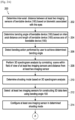
- the embodiments herein provide a method for constructing a three dimensional (3D) data item in a bendable device (100).
- the method includes determining, by the bendable device (100), an inter-axial distance between at least two imaging sensors of the bendable device (100) based on a biometric associated with eyes. Further, the method includes determining, by the bendable device (100), a bending angle of the bendable device (100) based on the inter-axial distance. Further, the method includes constructing, by the bendable device (100), the 3D data item using the bending angle of the bendable device (100).
- the method for constructing, by the bendable device (100), the 3D data item using the bending angle of the bendable device (100) includes detecting a bending action performed by the user to achieve the determined bending angle.
- the method also includes performing a 3D spectrogram analysis by correlating a scene within a field of view of the at least two imaging sensors and a distance from the at least two imaging sensor. Further, the method includes determining a shooting mode based on the 3D spectrogram analysis and selecting the at least two imaging sensors for constructing the 3D data item using the bending angle. Furthermore, the method also includes configuring the at least one imaging sensor in the determined shooting mode and constructing the 3D data item using the bending angle of the bendable device (100).
- the method further includes determining, by the bendable device (100), a position of the at least one imaging sensor and configuring, by the bendable device (100), the at least one imaging sensor in the determined position. Further, the method also includes constructing, by the bendable device (100), the 3D data item using the bending angle of the bendable device (100).
- the shooting mode is at least one of a parallel shooting and a converged shooting.
- the method for determining, by the bendable device (100), the position of the at least one imaging sensor includes performing at least one of a rotation of the at least one imaging sensor, popping-up of the at least one imaging sensor from the bendable device (100), tilting of the at least one imaging sensor.
- the method for selecting, by the bendable device (100), the at least two imaging sensors for constructing the 3D data item using the bending angle includes determining a personalized biometric associated with the eyes for the user, wherein the personalized biometric associated with the eyes is specific to a user and identifying the at least two imaging sensors to be used for constructing the 3D data item based on the personalized biometric associated with the eyes for the user and a generalized biometric associated with the eyes, wherein the generalized biometric associated with the eyes is an average of the biometric associated with the eyes of a plurality of users. Further, the method also includes selecting the at least two imaging sensors for constructing the 3D data item using the bending angle.
- the biometric associated with the eyes is unique to the user of the bendable device (100), and wherein the biometric associated with the eyes is determined using the at least one imaging sensor of the bendable device (100).
- the bendable device (100) comprises at least two foldable display, a mechanical hinge along an axis of the at least two foldable display which enables folding of the at least two foldable display around the axis.
- the bendable device (100) is a flexible display which is rollable and foldable.
- the method further includes determining, by the bendable device (100), the inter-axial distance between the at least two imaging sensors of the bendable device (100) is equal to the biometric associated with the eyes; and automatically constructing, by the bendable device (100), the 3D data item of a scene within a field of view of the at least two imaging sensors, using the bending angle of the bendable device (100).
- the biometric of the eyes is one of the inter-pupillary distance (IPD), an inter-iris distance (IID), an inter- retinal distance (IRD).
- IPD inter-pupillary distance
- IID inter-iris distance
- IRD inter- retinal distance
- a realistic 3D view with personalized 3D content is constructed by the bendable device (100).
- the bendable device (100) automatically records the scene in a 3D mode.
- FIGS. 1A through 13 where similar reference characters denote corresponding features consistently throughout the figures, there are shown embodiments.
- FIG. 1A is a block diagram of the bendable device (100) for constructing the three dimensional (3D) data item using the bending angle of the bendable device (100), according to an embodiment as disclosed herein.
- the bendable device (100) can be, for example, a mobile phone, a smart phone, Personal Digital Assistant (PDA), a tablet, a wearable device, or the like.
- the bendable device (100) includes at least two imaging sensors (120), a processor (140), a memory (160) and a bendable display (180).
- the at least two imaging sensors (120) are configured to preview a scene within the field of view of the at least two imaging sensors (120). Further, the at least two imaging sensors (120) are configured to determine the biometric associated with the eyes.
- the biometric associated with the eyes is unique to a particular user.
- the biometric associated with the eyes is one of the inter-pupillary distance (IPD), an inter-iris distance (IID), an inter- retinal distance (IRD).
- the processor (140) is configured to determine the inter-axial distance between the at least two imaging sensors (120) of the bendable device (100) based on the biometric associated with the eyes.
- the processor (140) is also configured to determine the bending angle of the bendable device (100) based on the inter-axial distance and a length of the bendable device (100) across an axis of the bendable device (100) and construct the 3D data item using the bending angle of the bendable device (100).
- the memory (160) can include non-volatile storage elements. Examples of such non-volatile storage elements may include magnetic hard discs, optical discs, floppy discs, flash memories, or forms of electrically programmable memories (EPROM) or electrically erasable and programmable (EEPROM) memories.
- the memory (160) may, in some examples, be considered a non-transitory storage medium.
- the term "non-transitory” may indicate that the storage medium is not embodied in a carrier wave or a propagated signal. However, the term “non-transitory” should not be interpreted that the memory (160) is non-movable.
- the memory (160) is configured to store large amounts of information than the memory (160).
- a non-transitory storage medium may store data that can, over time, change (e.g., in Random Access Memory (RAM) or cache).
- RAM Random Access Memory
- the bendable display (180) is configured to display the scene within the field of view of the at least two imaging sensors (120). Further, the bendable display (180) is configured to display the 3D data item which is constructed by the processor (140) in the determined shooting mode. Further, the 3D data item may be displayed either on the entire display area of the bendable display (180) or in a portion of the bendable display (180).
- FIG. 1A shows the hardware elements of the bendable device (100), it is to be understood that other embodiments are not limited thereon. In other embodiments, the bendable device (100) may include less or more elements. Further, the labels or names of the elements are used only for illustrative purposes. One or more components can be combined together to perform same or substantially similar functions.
- FIG. 1B illustrates a block diagram of various components of the processor (140) for constructing the three dimensional (3D) data item, according to an embodiment as disclosed herein.
- the processor (140) includes an IAD determination engine (142), a bending angle management engine (144), a 3D spectrogram analyzer (146), a shooting mode determination engine (148), a imaging sensors management engine (150), a 3D data item construction engine (152), a biometric database (154) and a 3D data item database (156).
- the IAD determination engine (142) is configured to determine the inter-axial distance (IAD) between the at least two imaging sensors (120) of the bendable device (100) based on the biometric associated with the eyes. Further, the IAD determination engine (142) is capable of measuring the IAD for a plurality of users. The IAD determination engine (142) is also configured to determine a generalized biometric associated with the eyes based on the personalized biometric associated with the eyes of the plurality of users, which is stored in the biometric database (154).
- IAD inter-axial distance
- the bending angle management engine (144) is also configured to detect a bending action performed by the user where the IAD between the at least two imaging sensors (120) of the bendable device (100) is equal to the biometric associated with the eyes.
- the 3D spectrogram analyzer (146) is configured to perform the 3D spectrogram analysis by correlating the scene within the field of view of the at least two imaging sensors (120) and the distance from the at least two imaging sensor (120) to an object in the scene.
- the shooting mode determination engine (148) is configured to receive the input from the 3D spectrogram analyzer (146) and determine the shooting mode based on the 3D spectrogram analysis.
- the shooting mode is at least one of a parallel shooting and a converged shooting.
- the imaging sensors management engine (150) is configured to select the at least two imaging sensors for constructing the 3D data item using the bending angle based on the shooting mode which is selected. Further, the imaging sensors management engine (150) also configures the at least one imaging sensor (120) in the determined shooting mode.
- the imaging sensors management engine (150) is configured to determine a position of the at least one imaging sensor (120) and configure the at least one imaging sensor (120) in the determined position.
- the determined position of the at least one imaging sensor (120) is achieved performing at least one of a rotation of the at least one imaging sensor (120), popping-up of the at least one imaging sensor (120) from the bendable device (100), tilting of the at least one imaging sensor (120).
- the 3D data item construction engine (152) is configured to construct the 3D data item of the objects in the scene within the field of view of the at least one imaging sensor (120) using the bending angle of the bendable device (100).
- the 3D data item construction engine (152) is configured to automatically construct the 3D data item of the scene within the field of view of the at least two imaging sensors (120) using the bending angle, when the bending angle management engine (144) detects that the IAD between the at least two imaging sensors (120) of the bendable device (100) is equal to the biometric associated with the eyes.
- the biometric database (154) is configured to store the personalized biometric associated with the eyes for a plurality of users, which is used to determine the generalized biometric associated with the eyes.
- the generalized biometric associated with the eyes is an average of the biometric associated with the eyes for the plurality of users.
- the 3D data item database (156) is configured to store the 3D data item which is constructed by the 3D data item construction engine (152).
- FIG. 2A and 2B are flow charts 200 illustrating a method for constructing the 3D data item in the bendable device (100), according to an embodiment as disclosed herein.
- the bendable device (100) determines the inter-axial distance between the at least two imaging sensors (120) of bendable device (100) based on the biometric associated with the eyes.
- the processor (140) can be configured to determine the inter-axial distance between the at least two imaging sensors (120) of bendable device (100) based on the biometric associated with the eyes.
- the bendable device (100) determines the bending angle based on the inter-axial distance and the length of the bendable device (100) across the axis of the bendable device (100).
- the processor (140) can be configured to determine the bending angle based on the inter-axial distance and the length of the bendable device (100) across the axis of the bendable device (100).
- the bendable device (100) detects the bending action performed by the user to achieve the determined bending angle.
- the processor (140) can be configured to detect the bending action performed by the user to achieve the determined bending angle.
- the bendable device (100) performs the 3D spectrogram analysis by correlating the scene within the field of view of the at least two imaging sensors (120) and the distance from at least two imaging sensor (120).
- the processor (140) can be configured to perform the 3D spectrogram analysis by correlating the scene within the field of view of the at least two imaging sensors (120) and the distance from at least two imaging sensor (120).
- the bendable device (100) determines the shooting mode based on the 3D spectrogram analysis.
- the processor (140) can be configured to determine the shooting mode based on the 3D spectrogram analysis.
- the bendable device (100) selects the at least two imaging sensors (120) for constructing 3D data item using bending angle.
- the processor (140) can be configured to select the at least two imaging sensors (120) for constructing 3D data item using bending angle.
- the bendable device (100) configures the at least one imaging sensor (120) in the determined shooting mode.
- the processor (140) can be configured to configure the at least one imaging sensor (120) in the determined shooting mode.
- the bendable device (100) constructs the 3D data item using the bending angle.
- the processor (140) can be configured to) constructs the 3D data item using the bending angle.
- the bendable device (100) determines the position of the at least one imaging sensor (120).
- the processor (140) can be configured to determine the position of the at least one imaging sensor (120).
- the bendable device (100) configures the at least one imaging sensor (120) in the determined position.
- the processor (140) can be configured to arrange the at least one imaging sensor (120) in the determined position.
- step 222 the bendable device (100) loops to step 216.
- the bendable device (100) determines the inter-axial distance between the at least two imaging sensors (120) of bendable device (100) is equal to the biometric associated with the eyes.
- the processor (140) can be configured to determine the inter-axial distance between the at least two imaging sensors (120) of bendable device (100) is equal to the biometric associated with the eyes.
- the bendable device (100) automatically constructs the 3D data item of the scene within the field of view of the at least two imaging sensors (120), using the bending angle.
- the processor (140) can be configured to automatically construct the 3D data item of the scene within the field of view of the at least two imaging sensors (120), using the bending angle of the bendable device (100).
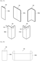
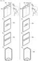
- FIG. 3A and 3B are examples illustrating the various types of bendable device (100) which are used for constructing the 3D data item, according to an embodiment as disclosed herein.
- the bendable device (100) includes at least two foldable displays, a mechanical hinge along an axis of the at least two foldable display which enables the folding of the at least two foldable display around the axis, as shown in 302a-306a of the FIG. 3A .
- the bendable device (100) is in a closed state where the at least two foldable display are folded around the axis.
- the bendable device (100) makes an angle of 180° between the at least two foldable display.
- the bendable device (100) is bent at an angle, which is called the bending angle.
- the bendable device (100) includes the at least one imaging sensor (120) which are capable of popping-out of the structure of the bendable device (100) when an image needs to be captured.
- the bendable device (100) includes the at least one imaging sensor (120) which are embedded on the body of the bendable device (100) and are used to capture the image.
- the bendable device (100) can be the flexible display which is rollable and foldable, as shown in FIG. 3B .
- the flexible display of the bendable device (100) is rolled completely in the shape of a cylinder.
- the bendable device (100) is opened up to be flat at the flexible display portion and rolled at the ends.
- FIG. 4A and 4B illustrate rotations of the at least one imaging sensor (120) of the bendable device (100) for constructing the 3D data item, according to an embodiment as disclosed herein.
- a first imaging sensor (120a) is provided on a first flexible display of the bendable device (100) and a set of three imaging sensors (120b-120d) is provided on a second flexible display of the bendable device (100).
- the bendable device (100) when the bendable device (100) determines the shooting mode to be used to construct the 3D data item, the bendable device (100) also determines the position of the first imaging sensor (120a). At 2, the position of the first imaging sensor (120a) is determined to enable the bendable device (100) to capture the scene in the determined shooting mode and construct the 3D data item of the scene.
- the at least one imaging sensor (120a) is provided in a movable pallet attached to the bendable device (100). Further, based on the shooting mode determined by the bendable device (100), the at least one imaging sensor (120a) in the movable pallet is rotated to construct the 3D data item.
- the at least one imaging sensor (120a) is mounted in a containing space of the bendable device (100) in a rotatable mode along with a locking module.
- the rotatable mode enables the at least one imaging sensor (120a) to turn over automatically after being released from the locking module. Therefore, the at least one imaging sensor (120a) is multifunctional and can be rotated to any angle to capture the scene, as shown in the FIG. 4A and the FIG. 4B .
- the at least one imaging sensor (120a) which is rotatable provides enhanced depth while capturing the scene.
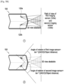
- FIG. 5A illustrates a method for determining the position of the at least one imaging sensor (120) of the bendable device (100) for constructing the 3D data item in the parallel shooting mode, according to an embodiment as disclosed herein.
- the bendable device (100) having the first imaging sensor (120a) and the second imaging sensor (120b) which are not rotatable and have a fixed position on the bendable device (100).
- a field of view of the first imaging sensor (120a) and a field of view of the second imaging sensor (120b) overlap, as shown in the FIG. 5A .
- a 3D view only of a portion of the scene which falls within the overlapping regions of the field of view of the first imaging sensor (120a) and the field of view of the second imaging sensor (120b) is captured in the parallel shooting mode.
- the parallel shooting mode is used to capture the 3D view of the far away objects.
- the bendable device (100) determines the position of the first imaging sensor (120a) and the second imaging sensor (120b) required to capture the 3d view of the scene in the parallel shooting mode.
- An angle of rotation of the first imaging sensor (120a) and an angle of rotation of the second imaging sensor (120b) is determined based on the bending angle.
- Angle of rotation of the first imaging sensor 120 a 90 ° ⁇ ⁇ 2
- Angle of rotation of the second imaging sensor 120 b 90 ° ⁇ ⁇ 2 where ⁇ is the bending angle.
- the bendable device (100) suggests the user to perform a bending action to achieve the bending angle which is required to configure the first imaging sensor (120a) and the second imaging sensor (120b) in the determined position. Therefore, the field of view of the first imaging sensor (120a) and the field of view of the second imaging sensor (120b) capture the 3D view of the scene in the parallel shooting mode, as shown at 2.
- FIG. 5B illustrates a method for determining the position of the at least one imaging sensor (120) of the bendable device (100) for constructing the 3D data item in the converged shooting mode, according to an embodiment as disclosed herein.
- the 3D view of only the portion of the scene which falls within the overlapping regions of the field of view of the first imaging sensor (120a) and the field of view of the second imaging sensor (120b) is captured in the converged shooting mode.
- the converged shooting mode is used to capture the 3D view of the nearby objects.
- the bendable device (100) determines the position of the first imaging sensor (120a) and the second imaging sensor (120b) required to capture the 3D view of the scene in the converged shooting mode.
- the angle of rotation of the first imaging sensor (120a) and the angle of rotation of the second imaging sensor (120b) is determined based on the bending angle.
- Angle of rotation of the first imaging sensor 120 a tan ⁇ 1 IAD 2 object distance
- Angle of rotation of the second imaging sensor 120 b tan ⁇ 1 IAD 2 object distance
- the bendable device (100) suggests the user to perform the bending action to achieve the bending angle which is required to configure the first imaging sensor (120a) and the second imaging sensor (120b) in the determined position. Therefore, the field of view of the first imaging sensor (120a) and the field of view of the second imaging sensor (120b) capture the 3D view of the scene in the converged shooting mode, as shown at 2.
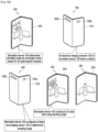
- FIG. 6A and 6B are examples illustrating the construction of the 3D data item using the bending angle of the bendable device (100) for the user, according to an embodiment as disclosed herein.
- the bendable device (100) determines the inter-pupillary distance (IPD) of the user as 60mm. Further, the bendable device (100) determines the inter-axial distance (IAD) between the at least two imaging sensors (120a, 120b) of the bendable device (100) based on the IPD of the user of the bendable device (100). At step 604, the bendable device (100) determines the bending angle as 37° based on the IAD and the length ( l / 2 ) of the bendable device (100) across the axis of the bendable device (100).
- IPD inter-pupillary distance
- IAD inter-axial distance
- the bendable device (100) displays a message on the screen of the bendable device (100) to prompt the user to bend the bendable device 100 to achieve the determined bending angle of 37°.
- the bendable device (100) determines the bending action performed by the user to achieve the bending angle of 37°.
- the bendable device (100) performs the 3D spectrogram analysis by correlating the scene within the field of view of the at least two imaging sensors (120a, 120b) and the distance from the at least two imaging sensor (120a, 120b) to the object. Further, the bendable device (100) determines the shooting mode based on the 3D spectrogram analysis as the converged mode.
- the bendable device (100) selects the first imaging sensors (120a) and the second imaging sensors (120b); and determines the position of the first imaging sensors (120a) and the second imaging sensors (120b) for constructing the 3D data item using the bending angle.
- the bendable device (100) configures the first imaging sensors (120a) and the second imaging sensors (120b) in the converged shooting mode and the determined position.
- the configuration of the second imaging sensors (120b) in the determined position includes rotation of the second imaging sensors (120b), as shown in FIG. 6B .
- the bendable device (100) constructs the 3D data item using the bending angle of the bendable device (100) which is displayed at step 618.
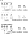
- FIG. 7A is an example illustrating the construction of the 3D data item using the bending angle of the bendable device (100) by selecting the shooting mode based on the IPD of the different users, according to an embodiment as disclosed herein.
- the bendable device (100) determines the IPD of the first user as 60mm.
- the bendable device (100) determines the IPD of the second user as 65mm. Further, the bendable device (100) determines the IAD based on the IPD of the respective users of the bendable device (100).
- the bendable device (100) determines the bending angle as 35° for the first user based on the IAD of the first user.
- the bendable device (100) determines the bending angle as 37° for the second user based on the IAD of the second user.
- the bendable device (100) displays a message on the screen of the bendable device (100) to prompt the first user to bend the bendable device 100 to achieve the determined bending angle of 35°.
- bendable device (100) prompts the second user to bend the bendable device 100 to achieve the determined bending angle of 37°.
- the bendable device (100) determines the bending action performed by the first user to achieve the bending angle of 35° and the bending action performed by the second user to achieve the bending angle of 37°, respectively.
- the bendable device (100) determines the shooting mode to be used for constructing the 3D view of the scene based on the 3D spectrogram analysis for the first user is converged mode and the second user is parallel mode respectively.
- the bendable device (100) selects the first imaging sensors (120a) and the second imaging sensors (120b) and determines the position of the first imaging sensors (120a) and the second imaging sensors (120b) for constructing the 3D data item using the bending angle for the first user. Further, the bendable device (100) configures the first imaging sensor (120a) and the second imaging sensor (120b) in the converged shooting mode and the determined position based on the bending angle for the first user, as shown in FIG. 7B .
- the bendable device (100) selects the first imaging sensors (120a) and the second imaging sensors (120b) and determines the position of the first imaging sensors (120a) and the second imaging sensors (120b) for constructing the 3D data item using the bending angle for the second user. Further, the bendable device (100) configures the first imaging sensor (120a) and the second imaging sensor (120b) in the parallel shooting mode and the determined position based on the bending angle for the second user, as shown in FIG. 7A .
- the bendable device (100) constructs the 3D data item using the bending angle for the first user and at step 716b, the bendable device (100) constructs the 3D data item using the bending angle for the second user.
- the bendable device (100) does not use a default shooting mode for the plurality of users who use the bendable device (100). Unlike to the conventional methods and systems, in the proposed method the bendable device (100) determines the best shooting mode to construct the 3D data item based on the IPD of the individual user.
- FIG. 8A is an example illustrating the varying degree of pop-up of the at least one imaging sensor (120) based on the personalized IPD of the user and the generalized IPD of the plurality of user of the bendable device (100), according to an embodiment as disclosed herein.
- the bendable device (100) has four imaging sensors (120a-120d) where the second imaging sensor (120b), the third imaging sensor (120c) and the fourth imaging sensor (120d) are popping-capable imaging sensors.
- the first imaging sensor (120a) is the fixed imaging sensor on the first display of the bendable device (100).
- the fourth imaging sensor (120d) is closest to the first imaging sensor (120a) and the second imaging sensor (120b) is farthest from the first imaging sensor (120a).
- the bendable device (100) determines the personalized IPD for the user using the at least one imaging sensor (120a). Further, based on the personalized IPD of the user, the bendable device (100) pops-up the second imaging sensor (120b).
- the bendable device (100) determines the personalized IPD for the user using the at least one imaging sensor (120) and compares the personalized IPD for the user with the generalized IPD for the plurality of users which is stored in the bendable device (100). The bendable device (100) determines that the difference between the personalized IPD and the generalized IPD are negligible. Further, the bendable device (100) pops-out the second imaging sensor (120b) and the third imaging sensor (120c) to capture the 3D data item using the personalized IPD and the generalized IPD.
- the bendable device (100) uses the first imaging sensor (120a) and the second imaging sensor (120b) to construct the 3D data item using the generalized IPD. Further, the bendable device (100) uses the first imaging sensor (120a) and the third imaging sensor (120c) to construct the 3D data item using the personalized IPD.
- the bendable device (100) determines that the difference between the personalized IPD and the generalized IPD are very large. Further, the bendable device (100) pops-out the second imaging sensor (120b), the third imaging sensor (120c) and the fourth imaging sensor (120d) to capture the 3D data item using the personalized IPD and the generalized IPD. Since the personalized IPD is smaller than the generalized IPD, the bendable device (100) uses the first imaging sensor (120a) and the second imaging sensor (120b) to construct the 3D data item using the generalized IPD. Further, the bendable device (100) uses the first imaging sensor (120a) and the fourth imaging sensor (120d) to construct the 3D data item using the personalized IPD.
- FIG. 8B is an example illustrating the selection of the at least two imaging sensor (120) based on the personalized IPD of the user and the generalized IPD of the plurality of users of the bendable device (100), according to an embodiment as disclosed herein.
- the personalized IPD of the user is large and the personalized IPD of the user is greater than the generalized IPD.
- the farthest imaging sensors i.e ., the first imaging sensor (120a) and the fourth imaging sensor (120d)
- the imaging sensors which are closer to each other i.e., the first imaging sensor (120a) and the third imaging sensor (120c) are chosen for constructing the 3D view of the scene using the generalized IPD.
- the personalized IPD of the user is equal to the generalized IPD.
- the farthest imaging sensors i.e., the first imaging sensor (120a) and the fourth imaging sensor (120d) are chosen for constructing the 3D view of the scene using the personalized IPD and the generalized IPD. Further, the farthest imaging sensors provide maximum range.
- a case 1 where the personalized IPD of the user is small and the generalized IPD is greater than the personalized IPD of the user.
- the farthest imaging sensors i.e., the first imaging sensor (120a) and the third imaging sensor (120c)
- the imaging sensors which are closer to each other i.e., the first imaging sensor (120a) and the second imaging sensor (120b) are chosen for constructing the 3D view of the scene using the personalized IPD.
- FIG. 8C illustrates the construction of a video of the 3D data item based on a plurality of frames from the at least two imaging sensor (120) of the bendable device (100), according to an embodiment as disclosed herein.
- the bendable device (100) can capture the video of the 3D data item with the personalized IPD and the generalized IPD simultaneously and store in a MPEG format in the bendable device (100).
- two separate imaging sensors of the at least one imaging sensor (120) are used to capture the frames with respect to each eye of the user, which are then packaged in a single file as a stereoscopic 3D recording.
- the MPEG format is used to store the two videos as the MPEG format supports saving the stereoscopic 3D video in a side-by-side video format.
- a first user with personalized IPD as IPD 1.
- the video frames from the first imaging sensor (120a) corresponding to the first eye of the first user and the video frames from the second imaging sensor (120b) corresponding to the second eye of the first user are stored as the stereoscopic 3D video called file 1.
- the file 2 corresponds to the stereoscopic 3D video for the second user which is captured using the first imaging sensor (120a) and the third imaging sensor (120c).
- the file 3 corresponds to the stereoscopic 3D video for the third user which is captured using the first imaging sensor (120a) and the fourth imaging sensor (120d), as shown in FIG. 8C .
- the bendable device (100) also simultaneously records the stereoscopic 3D video using the generalized IPD every time the stereoscopic 3D video is recorded using the personalized IPD of the respective users.
- FIG. 9 is an example illustrating the construction of the 3D data item simultaneously based on the personalized IPD and the generalized IPD, according to an embodiment as disclosed herein.
- the bendable device (100) determines the personalized IPD for the user as 60mm.
- the bendable device (100) determines the bending angle based on the personalized IPD. Further, the bendable device (100) also compares the personalized IPD with the generalized IPD ( i.e., 65mm) and determines that the personalized IPD is less than the generalized IPD.
- the bendable device (100) displays a message on the screen of the bendable device (100), prompting the user to perform the bending action to achieve the bending angle of 37°.
- the user bends the bendable device (100) to the bending angle.
- the bendable device (100) determines the shooting mode as the converged shooting mode based on the 3D spectrogram analysis. Further, the bendable device (100) determines the position of the at least one imaging sensors (120) and configures the at least two imaging sensors (120) in the determined position.
- the bendable device (100) includes the at least two imaging sensors (120) which are fixed.
- the bendable device (100) configures the at least two imaging sensors (120) by rotating the second imaging sensor (120b). Further, the bendable device (100) constructs the 3D data item based on the personalized IPD using the first imaging sensor (120a) and the second imaging sensor (120b). The bendable device (100) also simultaneously constructs the 3D data item based on the generalized IPD using the first imaging sensor (120a) and the fourth imaging sensor (120d).
- the bendable device (100) includes the at least two imaging sensors (120) which can be popped-out.
- the bendable device (100) configures the at least two imaging sensors (120) by popping-out the second imaging sensor (120b), the third imaging sensor (120c) and the fourth imaging sensor (120d).
- the bendable device (100) constructs the 3D data item based on the personalized IPD using the first imaging sensor (120a) and the second imaging sensor (120b).
- the bendable device (100) also simultaneously constructs the 3D data item based on the generalized IPD using the first imaging sensor (120a) and the fourth imaging sensor (120d).
- the bendable device (100) constructs the 3D data item based on the generalized IPD and the personalized IPD of the user simultaneously. Further, the differences between the 3D data item constructed based on the generalized IPD and the personalized IPD of the user are clearly shown in FIG. 9 . Therefore, the proposed method provides personalized construction of the 3D data item for the specific users and also the generalized construction of the 3D data item, which can be shared/ viewed by different users.
- FIG. 10 illustrates an example scenario where the bendable device (100) automatically records the scene in the 3D mode when the user bends the bendable device (100) to a specific angle, according to an embodiment as disclosed herein.
- step 1002 consider that the user of the bendable device (100) is recording a video in a closed mode i.e., the first flexible display and the second flexible display of the bendable device (100) are folded onto each other. Further, at step 1004, the user records the video in a completely open mode i.e., the first flexible display and the second flexible display of the bendable device (100) are opened-up and are at 180° to each other. However, the completely open mode is a non 3D recording by default and the video is recorded in the non-3D recording mode.
- the user performs the bending action on the bendable device (100).
- the IAD of the bendable device (100) becomes equal to the IPD of the user of the bendable device (100).
- the bendable device (100) automatically records the scene in the 3D mode, as shown in step 1008.
- the user of the bendable device (100) can manually switch to the non 3D recording, in case the user does not want to record the video in the 3D mode.
- the bendable device (100) continuously compares the IAD of the bendable device (100) with the IPD of the user, and automatically switches to record the scene in the 3D mode, when the IAD of the bendable device (100) becomes equal to the IPD of the user.
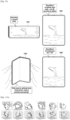
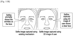
- FIGS. 11A and 11B illustrate examples of constructing a selfie image of the user of the bendable device (100) based on an image captured in the 3D mode, according to an embodiment as disclosed herein.
- a better selfie image of the user can be obtained if the selfie image is captured in the 3D mode.
- the image captured in the 3D mode provides a larger number of points for constructing the image of the user.
- the bendable device (100) will capture the selfie image by removing abnormalities from face of the user, which are recognized in the 3D mode.
- the bendable device (100) captures the image of the user in the 3D mode.
- the image captured in the 3D mode is analyzed and all abnormalities, spots and depth of eye bags are predefined and noted by the bendable device (100).
- FIG. 11B shows a better selfie in real-time.
- a simplify3D (S3D) view along with variable inter-axial distance and convergence provides the bendable device (100) with more information about the user (i.e., the user whose image is captured) than a single image.
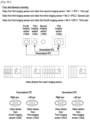
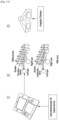
- FIG. 12A illustrates a deep learning network based model providing enhanced security to the bendable device (100), according to an embodiment as disclosed herein.
- the bendable device (100) includes a 4 layer deep learning network and which is trained for better security.
- the 4 layer deep learning network which is used in the bendable device (100) provides enhanced security due to the availability of the plurality of facial points in the 3D image due to increased depth. Therefore, the proposed bendable device (100) provides enhanced secure face unlocking mechanism.
- an input_shape (160) which represents the number of facial points that are used by the 4 layer deep learning network.
- classifier functions are used in the 4 layer deep learning network for predicting an output.
- the bendable device (100) uses a soft max classifier for training and retraining of the 4 layer deep learning network.
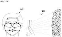
- FIG. 12B is an example illustrating enhanced security feature in the bendable device (100) based on deep learning, according to an embodiment as disclosed herein.
- an existing two dimensional (2D) face image which is used for facial recognition to unlock the bendable device (100) is shown.
- the existing 2D technique captures about 23 points from the user's face to construct the information about the user to unlock the phone.
- the proposed deep learning technique which uses the 3D image for facial recognition is shown.
- the proposed deep learning technique captures more than 4000 points from the user's face to construct the information about the user to unlock the phone. Further, the proposed deep learning technique enables the bendable device (100) to use two images from a variable IAD to match the 3D Model. The use of the variable IAD will assure that no two images can hack the bendable device (100) any time.
Landscapes
- Engineering & Computer Science (AREA)
- Theoretical Computer Science (AREA)
- Physics & Mathematics (AREA)
- Computer Hardware Design (AREA)
- General Physics & Mathematics (AREA)
- General Engineering & Computer Science (AREA)
- Human Computer Interaction (AREA)
- Multimedia (AREA)
- Signal Processing (AREA)
- Optics & Photonics (AREA)
- Computing Systems (AREA)
- Geometry (AREA)
- Computer Graphics (AREA)
- Mathematical Physics (AREA)
- Studio Devices (AREA)
- Measurement Of The Respiration, Hearing Ability, Form, And Blood Characteristics Of Living Organisms (AREA)
- Endoscopes (AREA)
- Testing, Inspecting, Measuring Of Stereoscopic Televisions And Televisions (AREA)
Claims (11)
- Verfahren zum Herstellen eines stereoskopischen dreidimensionalen (3D) Datenelements in einer biegbaren Vorrichtung, wobei das Verfahren Folgendes umfasst:
Bestimmen, durch die biegbare Vorrichtung (100), eines interaxialen Zielabstands zwischen zwei Bildgebungssensoren (120) der biegbaren Vorrichtung basierend auf einer Biometrie, wobei:die Biometrie ein Abstand zwischen einem linken Auge eines Benutzers und einem rechten Auge des Benutzers ist,ein erster Bildgebungssensor (120a) der zwei Bildgebungssensoren auf einer ersten Anzeige der biegbaren Vorrichtung angeordnet ist,ein zweiter Bildgebungssensor (120b) der zwei Bildgebungssensoren auf einer zweiten Anzeige der biegbaren Vorrichtung angeordnet ist unddie erste und die zweite faltbare Anzeige mit einem Scharnier verbunden sind, sodass ein variabler Biegewinkel zwischen den Anzeigen gebildet wird;Bestimmen eines Zielbiegewinkels der biegbaren Vorrichtung durch die biegbare Vorrichtung basierend auf dem interaxialen Zielabstand; undHerstellen des 3D-Datenelements durch die biegbare Vorrichtung unter Verwendung des Zielbiegewinkels der biegbaren Vorrichtung durch Erfassen von Bildern einer Szene unter Verwendung jedes der zwei Bildgebungssensoren, während der variable Biegewinkel an dem Zielbiegewinkel liegt,wobei das Herstellen des 3D-Datenelements unter Verwendung des Zielbiegewinkels Folgendes umfasst:Bestimmen einer personalisierten Biometrie, die den Augen des Benutzers zugeordnet ist, wobei die personalisierte Biometrie, die den Augen zugeordnet ist, spezifisch für den Benutzer ist;Identifizieren von drei Bildgebungssensoren, die zum Herstellen des 3D-Datenelements basierend auf der personalisierten Biometrie, die den Augen des Benutzers zugeordnet ist, und einer generalisierten Biometrie zu verwenden sind, wobeidie generalisierte Biometrie ein Durchschnitt der Biometrie ist, die den Augen einer Vielzahl von Benutzern zugeordnet ist, unddie drei Bildgebungssensoren die zwei Bildgebungssensoren, die zum Herstellen des 3D-Datenelements basierend auf der personalisierten Biometrie zu verwenden sind, und einen weiteren Bildgebungssensor, der in Kombination mit einem der zwei Bildgebungssensoren zum Herstellen des 3D-Datenelements basierend auf der generalisierten Biometrie zu verwenden ist, umfassen;
undAuswählen der drei Bildgebungssensoren zum Herstellen des 3D-Datenelements unter Verwendung des Zielbiegewinkels. - Verfahren nach Anspruch 1, wobei das Herstellen des 3D-Datenelements durch die biegbare Vorrichtung unter Verwendung des Biegewinkels der biegbaren Vorrichtung Folgendes umfasst:Erkennen einer durch den Benutzer durchgeführten Biegeaktion, um den bestimmten Zielbiegewinkel zu erreichen;Durchführen einer 3D-Spektrogrammanalyse durch Korrelieren von Bildern, die durch die zwei Bildgebungssensoren der Szene innerhalb eines Sichtfelds der zwei Bildgebungssensoren erlangt wurden, und einer Entfernung eines Objekts in der Szene von den zwei Bildgebungssensoren;Bestimmen eines Aufnahmemodus basierend auf der 3D-Spektrogrammanalyse, wobei der Aufnahmemodus mindestens einer von einem parallelen Aufnahmemodus und einem konvergenten Aufnahmemodus ist;Auswählen der zwei Bildgebungssensoren zum Herstellen des 3D-Datenelements unter Verwendung des Zielbiegewinkels;Konfigurieren der zwei Bildgebungssensoren in dem bestimmten Aufnahmemodus; undHerstellen des 3D-Datenelements unter Verwendung des Zielbiegewinkels der biegbaren Vorrichtung.
- Verfahren nach Anspruch 2, ferner umfassend:Bestimmen von Zielpositionen der zwei Bildgebungssensoren durch die biegbare Vorrichtung;Konfigurieren der zwei Bildgebungssensoren in den bestimmten Positionen durch die biegbare Vorrichtung; undHerstellen des 3D-Datenelements durch die biegbare Vorrichtung unter Verwendung des Biegewinkels der biegbaren Vorrichtung.
- Verfahren nach Anspruch 1, wobei das Konfigurieren der Positionen der zwei Bildgebungssensoren durch die biegbare Vorrichtung Folgendes umfasst:
Durchführen mindestens eines von einer Drehung von mindestens einem der zwei Bildgebungssensoren um seine optische Achse, eines Herausspringens von mindestens einem der zwei Bildgebungssensoren aus der biegbaren Vorrichtung oder einem Neigen der optischen Achse von mindestens einem der zwei Bildgebungssensoren. - Verfahren nach Anspruch 1, wobei die personalisierte Biometrie von einem Benutzer der biegbaren Vorrichtung unter Verwendung der zwei Bildgebungssensoren der biegbaren Vorrichtung bestimmt wird.
- Verfahren nach Anspruch 1, ferner umfassend:Bestimmen, durch die biegbare Vorrichtung, dass der interaxiale Zielabstand zwischen den zwei Bildgebungssensoren der biegbaren Vorrichtung gleich der Biometrie ist; undautomatisches Herstellen des 3D-Datenelements einer Szene innerhalb eines Sichtfelds der zwei Bildgebungssensoren durch die biegbare Vorrichtung unter Verwendung des Biegewinkels der biegbaren Vorrichtung.
- Verfahren nach Anspruch 1, wobei der Zielbiegewinkel unter Verwendung des interaxialen Zielabstands und der Abstände zwischen jedem der zwei Bildgebungssensoren und dem Scharnier der biegbaren Vorrichtung bestimmt wird.
- Verfahren nach Anspruch 1, wobei die Biometrie der Augen eines von einem Pupillenabstand (IPD), einem Irisabstand (IID) oder einem Netzhautabstand (IRD) ist.
- Biegbare Vorrichtung zum Herstellen eines stereoskopischen dreidimensionalen (3D) Datenelements, wobei die biegbare Vorrichtung Folgendes umfasst:einen Speicher;mindestens zwei Bildgebungssensoren;eine erste Anzeige, die einen ersten Bildgebungssensor der mindestens zwei Bildgebungssensoren aufweist;eine zweite Anzeige, die einen zweiten Bildgebungssensor der mindestens zwei Bildgebungssensoren aufweist;ein Scharnier, das die erste Anzeige und die zweite Anzeige verbindet, sodass ein variabler Biegewinkel zwischen den Anzeigen gebildet wird; undeinen Prozessor, der mit dem Speicher gekoppelt ist, wobei der Prozessor zu Folgendem konfiguriert ist:Bestimmen eines interaxialen Zielabstands zwischen dem ersten und dem zweiten Bildgebungssensor der biegbaren Vorrichtung basierend auf einer Biometrie, wobei die Biometrie ein Abstand zwischen dem linken Auge eines Benutzers und dem rechten Auge des Benutzers ist;Bestimmen eines Zielbiegewinkels der biegbaren Vorrichtung basierend auf dem interaxialen Zielabstand; undHerstellen des 3D-Datenelements unter Verwendung des Zielbiegewinkels der biegbaren Vorrichtung durch Erfassen von Bildern einer Szene unter Verwendung jedes der zwei Bildgebungssensoren, während der variable Biegewinkel an dem Zielbiegewinkel liegt,wobei der Prozessor zu Folgendem konfiguriert ist:Bestimmen einer personalisierten Biometrie, die den Augen des Benutzers zugeordnet ist, wobei die personalisierte Biometrie, die den Augen zugeordnet ist, spezifisch für den Benutzer ist;Identifizieren von drei Bildgebungssensoren, die zum Herstellen des 3D-Datenelements basierend auf der personalisierten Biometrie, die den Augen des Benutzers zugeordnet ist, und einer generalisierten Biometrie zu verwenden sind, wobeidie generalisierte Biometrie ein Durchschnitt der Biometrie ist, die den Augen einer Vielzahl von Benutzern zugeordnet ist, unddie drei Bildgebungssensoren die zwei Bildgebungssensoren, die zum Herstellen des 3D-Datenelements basierend auf der personalisierten Biometrie zu verwenden sind, und einen weiteren Bildgebungssensor, der in Kombination mit einem der zwei Bildgebungssensoren zum Herstellen des 3D-Datenelements basierend auf der generalisierten Biometrie zu verwenden ist, umfassen;
undAuswählen der drei Bildgebungssensoren zum Herstellen des 3D-Datenelements unter Verwendung des Zielbiegewinkels. - Biegbare Vorrichtung nach Anspruch 9, wobei der Prozessor ferner dazu konfiguriert ist, gemäß einem der Verfahren in den Ansprüchen 2 bis 8 betrieben zu werden.
- Biegbare Vorrichtung nach Anspruch 9, wobei die biegbare Vorrichtung eine flexible Anzeige ist, die rollbar und faltbar ist.
Applications Claiming Priority (2)
| Application Number | Priority Date | Filing Date | Title |
|---|---|---|---|
| IN201941032000 | 2019-08-07 | ||
| PCT/KR2019/018393 WO2021025241A1 (en) | 2019-08-07 | 2019-12-24 | Method and bendable device for constructing 3d data item |
Publications (4)
| Publication Number | Publication Date |
|---|---|
| EP3969980A1 EP3969980A1 (de) | 2022-03-23 |
| EP3969980A4 EP3969980A4 (de) | 2022-06-29 |
| EP3969980B1 true EP3969980B1 (de) | 2024-04-24 |
| EP3969980C0 EP3969980C0 (de) | 2024-04-24 |
Family
ID=74498769
Family Applications (1)
| Application Number | Title | Priority Date | Filing Date |
|---|---|---|---|
| EP19940342.9A Active EP3969980B1 (de) | 2019-08-07 | 2019-12-24 | Verfahren und biegbare vorrichtung zur herstellung von 3d-datenelementen |
Country Status (5)
| Country | Link |
|---|---|
| US (1) | US11029522B2 (de) |
| EP (1) | EP3969980B1 (de) |
| KR (1) | KR102574288B1 (de) |
| CN (1) | CN114096935B (de) |
| WO (1) | WO2021025241A1 (de) |
Families Citing this family (3)
| Publication number | Priority date | Publication date | Assignee | Title |
|---|---|---|---|---|
| US11297260B1 (en) * | 2020-11-20 | 2022-04-05 | Donald Siu | Techniques for capturing video in landscape mode by a handheld device |
| US20220239832A1 (en) * | 2021-01-28 | 2022-07-28 | Motorola Mobility Llc | Image Processing as a Function of Deformable Electronic Device Geometry and Corresponding Devices and Methods |
| EP4468110A4 (de) * | 2022-02-14 | 2025-04-23 | Samsung Electronics Co., Ltd. | Mehrfachanzeigestruktur und elektronische vorrichtung damit |
Family Cites Families (42)
| Publication number | Priority date | Publication date | Assignee | Title |
|---|---|---|---|---|
| JPS6138379A (ja) * | 1984-07-30 | 1986-02-24 | シャープ株式会社 | 冷凍冷蔵庫 |
| JPH06138379A (ja) * | 1992-09-14 | 1994-05-20 | Nikon Corp | 視線検出装置付きカメラ |
| US20030113012A1 (en) * | 2001-08-17 | 2003-06-19 | Byoungyi Yoon | Method and system for controlling a screen ratio based on a photographing ratio |
| JP4090896B2 (ja) * | 2003-01-16 | 2008-05-28 | シャープ株式会社 | 情報端末装置 |
| US20060250322A1 (en) * | 2005-05-09 | 2006-11-09 | Optics 1, Inc. | Dynamic vergence and focus control for head-mounted displays |
| KR101297665B1 (ko) | 2007-10-18 | 2013-08-21 | 삼성테크윈 주식회사 | 회전형 카메라 모듈 |
| JP5073563B2 (ja) * | 2008-04-10 | 2012-11-14 | 株式会社山本精密 | 筐体相互の連結ユニット及び携帯端末 |
| US9025007B1 (en) * | 2009-04-28 | 2015-05-05 | Lucasfilm Entertainment Company Ltd. | Configuring stereo cameras |
| WO2011044936A1 (en) * | 2009-10-14 | 2011-04-21 | Nokia Corporation | Autostereoscopic rendering and display apparatus |
| JP5478205B2 (ja) * | 2009-11-13 | 2014-04-23 | 任天堂株式会社 | ゲーム装置、ゲームプログラム、ゲームシステムおよびゲーム制御方法 |
| KR101648453B1 (ko) * | 2010-02-08 | 2016-08-16 | 엘지전자 주식회사 | 휴대용 단말기 |
| US8922625B2 (en) * | 2009-11-19 | 2014-12-30 | Lg Electronics Inc. | Mobile terminal and controlling method thereof |
| US8928673B2 (en) * | 2010-06-30 | 2015-01-06 | Blue Sky Studios, Inc. | Methods and systems for 3D animation |
| US20120113232A1 (en) * | 2010-11-10 | 2012-05-10 | Sony Pictures Technologies Inc. | Multiple camera system and method for selectable interaxial separation |
| KR101852811B1 (ko) * | 2011-01-05 | 2018-04-27 | 엘지전자 주식회사 | 영상표시 장치 및 그 제어방법 |
| US8754961B2 (en) | 2011-08-17 | 2014-06-17 | Nokia Corporation | Apparatus and method for generating image data from overlapping regions of images |
| US9007300B2 (en) * | 2011-10-14 | 2015-04-14 | Blackberry Limited | Method and system to control a process with bend movements |
| US9851811B2 (en) * | 2012-02-20 | 2017-12-26 | Beijing Lenovo Software Ltd. | Electronic device and method for controlling the same |
| KR101303203B1 (ko) | 2012-03-14 | 2013-09-10 | 주식회사 펀진 | 정면 영상 생성 영상통화 장치 및 방법 |
| US9990004B2 (en) * | 2013-04-02 | 2018-06-05 | Samsung Dispaly Co., Ltd. | Optical detection of bending motions of a flexible display |
| KR20150039463A (ko) * | 2013-10-02 | 2015-04-10 | 삼성전자주식회사 | 3d 디스플레이장치 및 3d영상처리방법 |
| JP5922639B2 (ja) * | 2013-12-07 | 2016-05-24 | レノボ・シンガポール・プライベート・リミテッド | 折り畳み式の電子機器、表示システム、および表示方法 |
| CN103685892A (zh) | 2013-12-12 | 2014-03-26 | 路宽 | 自动翻转摄像头 |
| KR102292192B1 (ko) * | 2014-02-17 | 2021-08-23 | 엘지전자 주식회사 | 증강 현실 이미지를 디스플레이 하는 디스플레이 시스템 및 그 제어 방법 |
| US9712749B2 (en) * | 2014-02-27 | 2017-07-18 | Google Technology Holdings LLC | Electronic device having multiple sides |
| KR101632008B1 (ko) * | 2014-04-30 | 2016-07-01 | 엘지전자 주식회사 | 이동단말기 및 그 제어방법 |
| US10613585B2 (en) * | 2014-06-19 | 2020-04-07 | Samsung Electronics Co., Ltd. | Transparent display apparatus, group play system using transparent display apparatus and performance methods thereof |
| KR20160020189A (ko) * | 2014-08-13 | 2016-02-23 | 삼성전자주식회사 | 이미지 처리 방법 및 그 장치 |
| KR102171450B1 (ko) * | 2014-08-18 | 2020-10-29 | 엘지전자 주식회사 | 포터블 디바이스 및 그 제어 방법 |
| CA2863957C (en) * | 2014-09-16 | 2022-02-22 | Gtech Canada Ulc | 3d enhanced gaming machine with selectable 3d intensity level |
| US9792757B2 (en) * | 2014-09-16 | 2017-10-17 | Igt Canada Solutions Ulc | 3D enhanced gaming machine with selectable 3D intensity level |
| KR102137543B1 (ko) * | 2015-01-07 | 2020-08-13 | 삼성전자주식회사 | 벤딩 가능한 사용자 단말 장치 및 이의 디스플레이 방법 |
| DE112016000728T5 (de) * | 2015-02-12 | 2017-10-26 | Google Inc. | Kombinieren eines Displays mit engem Blickfeld und hoher Auflösung und eines Weitwinkeldisplays mit mittlerer Auflösung |
| US20160269720A1 (en) * | 2015-03-11 | 2016-09-15 | Oculus Vr, Llc | Flexible substrate display panel and panel geometry for ergonomics |
| WO2016182502A1 (en) | 2015-05-14 | 2016-11-17 | Medha Dharmatilleke | Multi purpose mobile device case/cover integrated with a camera system & non electrical 3d/multiple video & still frame viewer for 3d and/or 2d high quality videography, photography and selfie recording |
| KR102471302B1 (ko) * | 2015-07-07 | 2022-11-28 | 삼성전자 주식회사 | 헤드 마운트 디스플레이 장치 |
| GB2552090B (en) * | 2017-06-29 | 2021-06-16 | Inodyn Newmedia Gmbh | Front-facing camera and maximized display screen of a mobile device |
| US20170115489A1 (en) | 2015-10-26 | 2017-04-27 | Xinda Hu | Head mounted display device with multiple segment display and optics |
| CA2913369A1 (en) * | 2015-11-26 | 2017-05-26 | Peter Johann Kielland | Mount for a camera to be carried on a body-supported computer |
| KR20170076471A (ko) | 2015-12-24 | 2017-07-04 | 삼성전자주식회사 | 변형 가능한 디스플레이 장치 및 이를 이용한 영상 표시 방법 |
| KR102459831B1 (ko) * | 2015-12-28 | 2022-10-28 | 삼성전자주식회사 | 플렉서블 디스플레이를 포함하는 전자 장치 및 그 동작 방법 |
| US10409080B2 (en) * | 2017-02-01 | 2019-09-10 | Facebook Technologies, Llc | Spherical display using flexible substrates |
-
2019
- 2019-12-24 WO PCT/KR2019/018393 patent/WO2021025241A1/en not_active Ceased
- 2019-12-24 KR KR1020227001304A patent/KR102574288B1/ko active Active
- 2019-12-24 CN CN201980098006.8A patent/CN114096935B/zh active Active
- 2019-12-24 EP EP19940342.9A patent/EP3969980B1/de active Active
- 2019-12-30 US US16/729,724 patent/US11029522B2/en active Active
Also Published As
| Publication number | Publication date |
|---|---|
| EP3969980A4 (de) | 2022-06-29 |
| WO2021025241A1 (en) | 2021-02-11 |
| US20210041700A1 (en) | 2021-02-11 |
| EP3969980A1 (de) | 2022-03-23 |
| KR102574288B1 (ko) | 2023-09-07 |
| CN114096935A (zh) | 2022-02-25 |
| CN114096935B (zh) | 2024-05-03 |
| EP3969980C0 (de) | 2024-04-24 |
| US11029522B2 (en) | 2021-06-08 |
| KR20220024555A (ko) | 2022-03-03 |
Similar Documents
| Publication | Publication Date | Title |
|---|---|---|
| US9380207B1 (en) | Enabling multiple field of view image capture within a surround image mode for multi-lense mobile devices | |
| KR102021857B1 (ko) | 이동 단말기 및 그의 파노라마 촬영방법 | |
| EP3122021B1 (de) | Tragbares endgerät und verfahren zur steuerung davon | |
| EP3969980B1 (de) | Verfahren und biegbare vorrichtung zur herstellung von 3d-datenelementen | |
| CA2722924C (en) | 3d content aggregation built into devices | |
| US8922625B2 (en) | Mobile terminal and controlling method thereof | |
| WO2017075501A1 (en) | An imaging device and method for generating an undistorted wide view image | |
| KR20190139262A (ko) | 차량 손실 평가 이미지를 획득하기 위한 방법과 장치, 서버 및 단말기 디바이스 | |
| US7302113B2 (en) | Displaying digital images | |
| US8339469B2 (en) | Process for automatically determining a probability of image capture with a terminal using contextual data | |
| US20170064374A1 (en) | Mobile terminal and method for controlling the same | |
| JP5220951B1 (ja) | 立体映像出力装置及び立体映像出力方法 | |
| CN103595909A (zh) | 移动终端及其控制方法 | |
| US20170255841A1 (en) | Mobile terminal and method of controlling the same | |
| KR101675567B1 (ko) | 파노라마 촬영장치, 파노라마 촬영 시스템, 이를 이용한 파노라마 영상 생성 방법, 컴퓨터 판독가능 기록매체 및 컴퓨터 판독가능 기록매체에 저장된 컴퓨터 프로그램 | |
| KR20140060760A (ko) | 어레이 카메라, 휴대 단말기 및 그 동작 방법 | |
| KR102223281B1 (ko) | 이동단말기 및 그 제어방법 | |
| US20110090315A1 (en) | Capturing device, image processing method, and program | |
| US20150138309A1 (en) | Photographing device and stitching method of captured image | |
| US20120105601A1 (en) | Apparatus and method for creating three-dimensional panoramic image by using single camera | |
| CN110622501A (zh) | 图像处理装置及电子设备 | |
| US20120212606A1 (en) | Image processing method and image processing apparatus for dealing with pictures found by location information and angle information | |
| KR101809946B1 (ko) | 휴대용 단말기 | |
| JP2008211534A (ja) | 顔検知装置 | |
| WO2016024668A1 (ko) | 이동 단말기 및 그 제어 방법 |
Legal Events
| Date | Code | Title | Description |
|---|---|---|---|
| STAA | Information on the status of an ep patent application or granted ep patent |
Free format text: STATUS: THE INTERNATIONAL PUBLICATION HAS BEEN MADE |
|
| PUAI | Public reference made under article 153(3) epc to a published international application that has entered the european phase |
Free format text: ORIGINAL CODE: 0009012 |
|
| STAA | Information on the status of an ep patent application or granted ep patent |
Free format text: STATUS: REQUEST FOR EXAMINATION WAS MADE |
|
| 17P | Request for examination filed |
Effective date: 20211214 |
|
| AK | Designated contracting states |
Kind code of ref document: A1 Designated state(s): AL AT BE BG CH CY CZ DE DK EE ES FI FR GB GR HR HU IE IS IT LI LT LU LV MC MK MT NL NO PL PT RO RS SE SI SK SM TR |
|
| A4 | Supplementary search report drawn up and despatched |
Effective date: 20220531 |
|
| RIC1 | Information provided on ipc code assigned before grant |
Ipc: G06F 3/01 20060101ALI20220524BHEP Ipc: G06F 1/16 20060101ALI20220524BHEP Ipc: H04N 13/239 20180101ALI20220524BHEP Ipc: H04N 13/296 20180101ALI20220524BHEP Ipc: H04N 13/243 20180101AFI20220524BHEP |
|
| DAV | Request for validation of the european patent (deleted) | ||
| DAX | Request for extension of the european patent (deleted) | ||
| REG | Reference to a national code |
Ref country code: DE Ref legal event code: R079 Free format text: PREVIOUS MAIN CLASS: G06F0001160000 Ipc: H04N0013243000 Ref document number: 602019051152 Country of ref document: DE |
|
| RIC1 | Information provided on ipc code assigned before grant |
Ipc: G06F 3/01 20060101ALI20231017BHEP Ipc: G06F 1/16 20060101ALI20231017BHEP Ipc: H04N 13/189 20180101ALI20231017BHEP Ipc: H04N 13/239 20180101ALI20231017BHEP Ipc: H04N 13/296 20180101ALI20231017BHEP Ipc: H04N 13/243 20180101AFI20231017BHEP |
|
| GRAP | Despatch of communication of intention to grant a patent |
Free format text: ORIGINAL CODE: EPIDOSNIGR1 |
|
| STAA | Information on the status of an ep patent application or granted ep patent |
Free format text: STATUS: GRANT OF PATENT IS INTENDED |
|
| INTG | Intention to grant announced |
Effective date: 20231211 |
|
| GRAS | Grant fee paid |
Free format text: ORIGINAL CODE: EPIDOSNIGR3 |
|
| GRAA | (expected) grant |
Free format text: ORIGINAL CODE: 0009210 |
|
| STAA | Information on the status of an ep patent application or granted ep patent |
Free format text: STATUS: THE PATENT HAS BEEN GRANTED |
|
| AK | Designated contracting states |
Kind code of ref document: B1 Designated state(s): AL AT BE BG CH CY CZ DE DK EE ES FI FR GB GR HR HU IE IS IT LI LT LU LV MC MK MT NL NO PL PT RO RS SE SI SK SM TR |
|
| REG | Reference to a national code |
Ref country code: GB Ref legal event code: FG4D |
|
| REG | Reference to a national code |
Ref country code: CH Ref legal event code: EP |
|
| REG | Reference to a national code |
Ref country code: DE Ref legal event code: R096 Ref document number: 602019051152 Country of ref document: DE |
|
| REG | Reference to a national code |
Ref country code: IE Ref legal event code: FG4D |
|
| U01 | Request for unitary effect filed |
Effective date: 20240430 |
|
| U07 | Unitary effect registered |
Designated state(s): AT BE BG DE DK EE FI FR IT LT LU LV MT NL PT SE SI Effective date: 20240514 |
|
| PG25 | Lapsed in a contracting state [announced via postgrant information from national office to epo] |
Ref country code: IS Free format text: LAPSE BECAUSE OF FAILURE TO SUBMIT A TRANSLATION OF THE DESCRIPTION OR TO PAY THE FEE WITHIN THE PRESCRIBED TIME-LIMIT Effective date: 20240824 |
|
| PG25 | Lapsed in a contracting state [announced via postgrant information from national office to epo] |
Ref country code: HR Free format text: LAPSE BECAUSE OF FAILURE TO SUBMIT A TRANSLATION OF THE DESCRIPTION OR TO PAY THE FEE WITHIN THE PRESCRIBED TIME-LIMIT Effective date: 20240424 |
|
| PG25 | Lapsed in a contracting state [announced via postgrant information from national office to epo] |
Ref country code: GR Free format text: LAPSE BECAUSE OF FAILURE TO SUBMIT A TRANSLATION OF THE DESCRIPTION OR TO PAY THE FEE WITHIN THE PRESCRIBED TIME-LIMIT Effective date: 20240725 |
|
| PG25 | Lapsed in a contracting state [announced via postgrant information from national office to epo] |
Ref country code: ES Free format text: LAPSE BECAUSE OF FAILURE TO SUBMIT A TRANSLATION OF THE DESCRIPTION OR TO PAY THE FEE WITHIN THE PRESCRIBED TIME-LIMIT Effective date: 20240424 |
|
| PG25 | Lapsed in a contracting state [announced via postgrant information from national office to epo] |
Ref country code: PL Free format text: LAPSE BECAUSE OF FAILURE TO SUBMIT A TRANSLATION OF THE DESCRIPTION OR TO PAY THE FEE WITHIN THE PRESCRIBED TIME-LIMIT Effective date: 20240424 |
|
| PG25 | Lapsed in a contracting state [announced via postgrant information from national office to epo] |
Ref country code: PL Free format text: LAPSE BECAUSE OF FAILURE TO SUBMIT A TRANSLATION OF THE DESCRIPTION OR TO PAY THE FEE WITHIN THE PRESCRIBED TIME-LIMIT Effective date: 20240424 Ref country code: NO Free format text: LAPSE BECAUSE OF FAILURE TO SUBMIT A TRANSLATION OF THE DESCRIPTION OR TO PAY THE FEE WITHIN THE PRESCRIBED TIME-LIMIT Effective date: 20240724 Ref country code: IS Free format text: LAPSE BECAUSE OF FAILURE TO SUBMIT A TRANSLATION OF THE DESCRIPTION OR TO PAY THE FEE WITHIN THE PRESCRIBED TIME-LIMIT Effective date: 20240824 Ref country code: HR Free format text: LAPSE BECAUSE OF FAILURE TO SUBMIT A TRANSLATION OF THE DESCRIPTION OR TO PAY THE FEE WITHIN THE PRESCRIBED TIME-LIMIT Effective date: 20240424 Ref country code: GR Free format text: LAPSE BECAUSE OF FAILURE TO SUBMIT A TRANSLATION OF THE DESCRIPTION OR TO PAY THE FEE WITHIN THE PRESCRIBED TIME-LIMIT Effective date: 20240725 Ref country code: ES Free format text: LAPSE BECAUSE OF FAILURE TO SUBMIT A TRANSLATION OF THE DESCRIPTION OR TO PAY THE FEE WITHIN THE PRESCRIBED TIME-LIMIT Effective date: 20240424 Ref country code: RS Free format text: LAPSE BECAUSE OF FAILURE TO SUBMIT A TRANSLATION OF THE DESCRIPTION OR TO PAY THE FEE WITHIN THE PRESCRIBED TIME-LIMIT Effective date: 20240724 |
|
| PGFP | Annual fee paid to national office [announced via postgrant information from national office to epo] |
Ref country code: GB Payment date: 20241121 Year of fee payment: 6 |
|
| PG25 | Lapsed in a contracting state [announced via postgrant information from national office to epo] |
Ref country code: CZ Free format text: LAPSE BECAUSE OF FAILURE TO SUBMIT A TRANSLATION OF THE DESCRIPTION OR TO PAY THE FEE WITHIN THE PRESCRIBED TIME-LIMIT Effective date: 20240424 |
|
| PG25 | Lapsed in a contracting state [announced via postgrant information from national office to epo] |
Ref country code: RO Free format text: LAPSE BECAUSE OF FAILURE TO SUBMIT A TRANSLATION OF THE DESCRIPTION OR TO PAY THE FEE WITHIN THE PRESCRIBED TIME-LIMIT Effective date: 20240424 Ref country code: SK Free format text: LAPSE BECAUSE OF FAILURE TO SUBMIT A TRANSLATION OF THE DESCRIPTION OR TO PAY THE FEE WITHIN THE PRESCRIBED TIME-LIMIT Effective date: 20240424 |
|
| REG | Reference to a national code |
Ref country code: DE Ref legal event code: R097 Ref document number: 602019051152 Country of ref document: DE |
|
| PG25 | Lapsed in a contracting state [announced via postgrant information from national office to epo] |
Ref country code: SM Free format text: LAPSE BECAUSE OF FAILURE TO SUBMIT A TRANSLATION OF THE DESCRIPTION OR TO PAY THE FEE WITHIN THE PRESCRIBED TIME-LIMIT Effective date: 20240424 |
|
| U20 | Renewal fee for the european patent with unitary effect paid |
Year of fee payment: 6 Effective date: 20241226 |
|
| PG25 | Lapsed in a contracting state [announced via postgrant information from national office to epo] |
Ref country code: SM Free format text: LAPSE BECAUSE OF FAILURE TO SUBMIT A TRANSLATION OF THE DESCRIPTION OR TO PAY THE FEE WITHIN THE PRESCRIBED TIME-LIMIT Effective date: 20240424 Ref country code: SK Free format text: LAPSE BECAUSE OF FAILURE TO SUBMIT A TRANSLATION OF THE DESCRIPTION OR TO PAY THE FEE WITHIN THE PRESCRIBED TIME-LIMIT Effective date: 20240424 Ref country code: RO Free format text: LAPSE BECAUSE OF FAILURE TO SUBMIT A TRANSLATION OF THE DESCRIPTION OR TO PAY THE FEE WITHIN THE PRESCRIBED TIME-LIMIT Effective date: 20240424 Ref country code: CZ Free format text: LAPSE BECAUSE OF FAILURE TO SUBMIT A TRANSLATION OF THE DESCRIPTION OR TO PAY THE FEE WITHIN THE PRESCRIBED TIME-LIMIT Effective date: 20240424 |
|
| PLBE | No opposition filed within time limit |
Free format text: ORIGINAL CODE: 0009261 |
|
| STAA | Information on the status of an ep patent application or granted ep patent |
Free format text: STATUS: NO OPPOSITION FILED WITHIN TIME LIMIT |
|
| 26N | No opposition filed |
Effective date: 20250127 |
|
| PG25 | Lapsed in a contracting state [announced via postgrant information from national office to epo] |
Ref country code: MC Free format text: LAPSE BECAUSE OF FAILURE TO SUBMIT A TRANSLATION OF THE DESCRIPTION OR TO PAY THE FEE WITHIN THE PRESCRIBED TIME-LIMIT Effective date: 20240424 |
|
| REG | Reference to a national code |
Ref country code: CH Ref legal event code: PL |
|
| PG25 | Lapsed in a contracting state [announced via postgrant information from national office to epo] |
Ref country code: CH Free format text: LAPSE BECAUSE OF NON-PAYMENT OF DUE FEES Effective date: 20241231 |
|
| PG25 | Lapsed in a contracting state [announced via postgrant information from national office to epo] |
Ref country code: IE Free format text: LAPSE BECAUSE OF NON-PAYMENT OF DUE FEES Effective date: 20241224 |